EP4215965A1 - Optical fiber ribbon and sub-tape-type optical fiber ribbon - Google Patents
Optical fiber ribbon and sub-tape-type optical fiber ribbon Download PDFInfo
- Publication number
- EP4215965A1 EP4215965A1 EP21869341.4A EP21869341A EP4215965A1 EP 4215965 A1 EP4215965 A1 EP 4215965A1 EP 21869341 A EP21869341 A EP 21869341A EP 4215965 A1 EP4215965 A1 EP 4215965A1
- Authority
- EP
- European Patent Office
- Prior art keywords
- optical fiber
- ave
- coupling portions
- fiber ribbon
- sub
- Prior art date
- Legal status (The legal status is an assumption and is not a legal conclusion. Google has not performed a legal analysis and makes no representation as to the accuracy of the status listed.)
- Pending
Links
Images


Classifications
-
- G—PHYSICS
- G02—OPTICS
- G02B—OPTICAL ELEMENTS, SYSTEMS OR APPARATUS
- G02B6/00—Light guides; Structural details of arrangements comprising light guides and other optical elements, e.g. couplings
- G02B6/44—Mechanical structures for providing tensile strength and external protection for fibres, e.g. optical transmission cables
- G02B6/4401—Optical cables
- G02B6/4403—Optical cables with ribbon structure
-
- G—PHYSICS
- G02—OPTICS
- G02B—OPTICAL ELEMENTS, SYSTEMS OR APPARATUS
- G02B6/00—Light guides; Structural details of arrangements comprising light guides and other optical elements, e.g. couplings
- G02B6/44—Mechanical structures for providing tensile strength and external protection for fibres, e.g. optical transmission cables
- G02B6/4479—Manufacturing methods of optical cables
- G02B6/448—Ribbon cables
-
- G—PHYSICS
- G02—OPTICS
- G02B—OPTICAL ELEMENTS, SYSTEMS OR APPARATUS
- G02B6/00—Light guides; Structural details of arrangements comprising light guides and other optical elements, e.g. couplings
- G02B6/44—Mechanical structures for providing tensile strength and external protection for fibres, e.g. optical transmission cables
- G02B6/4401—Optical cables
- G02B6/4403—Optical cables with ribbon structure
- G02B6/4404—Multi-podded
Definitions
- Patent Literature 1 describes an optical fiber ribbon including a configuration in which an adhesive member is intermittently applied to both an upper surface side and a lower surface side of adjacent optical fibers, and when a thickness of the adhesive member is set as T and a diameter of the optical fiber is set as D, T ⁇ ( ⁇ 3 - 1)/2 ⁇ D is satisfied.
- Patent Literature 4 describes an optical fiber ribbon including a configuration in which two or more sub-ribbons are formed by intermittently adhering adjacent optical fibers with a first adhesive portion, the sub-ribbons are intermittently adhered and integrated by a second adhesive portion, a thickness of the first adhesive portion is set to a thickness that does not protrude from a tangent line passing through front surfaces of the optical fibers, and a thickness of the second adhesive portion is set to a thickness that protrudes from the above tangent line.
- a soft resin having a relatively low Young's modulus is used as a buffer layer.
- a hard resin having a relatively high Young's modulus is used as a protective layer.
- the cured product of the secondary resin has a Young's modulus of 900 Mpa or higher, preferably 1000 MPa or higher, and more preferably 1500 MPa or higher at a room temperature (for example, 23°C).
- the optical fiber ribbon 1A when the optical fiber ribbon 1A is stored in the optical fiber cable, a force is applied to bend the optical fiber ribbon 1A in a cross-sectional direction perpendicular to the longitudinal direction, and in this case, since the resin amounts (thicknesses TF and thicknesses TB) of the coupling portions 20 provided on both the front side and the back side of the optical fiber ribbon 1A are different, for example, by arranging the front coupling portions 21a to 21i, which are thicker, on the bent outside, breaking of the resin or peeling between the resin and the optical fibers can be less likely to occur.
- TF1 ave satisfies D/4 ⁇ TF1 ave ⁇ D/2 with respect to the outer diameter D of the optical fiber 110.
- TB1 ave when an average of thicknesses TB1 max from the virtual plane H to lowest points of the back coupling portions 122a and 122b is set as TB1 ave , TB1 ave satisfies TB1 ave ⁇ TF1 ave with respect to TF1 ave .
- the average TF1 ave and the average TB1 ave may be averages for each splice region arranged in parallel in the width direction of the optical fiber ribbon 1B, as in the case of the first embodiment.
Landscapes
- Physics & Mathematics (AREA)
- General Physics & Mathematics (AREA)
- Optics & Photonics (AREA)
- Engineering & Computer Science (AREA)
- Manufacturing & Machinery (AREA)
- Optical Fibers, Optical Fiber Cores, And Optical Fiber Bundles (AREA)
- Mechanical Coupling Of Light Guides (AREA)
Abstract
Description
- The present disclosure relates to an optical fiber ribbon and a sub-tape-type optical fiber ribbon.
- The present application claims priority based on a
Japanese Application No. 2020-155584 filed on September 16, 2020 - Patent Literature 1 describes an optical fiber ribbon including a configuration in which an adhesive member is intermittently applied to both an upper surface side and a lower surface side of adjacent optical fibers, and when a thickness of the adhesive member is set as T and a diameter of the optical fiber is set as D, T < (√3 - 1)/2 × D is satisfied.
-
Patent Literature 2 describes an optical fiber ribbon including a configuration in which a marking for identifying a number of the optical fiber ribbon is applied only to one side of a plurality of optical fibers arranged in parallel, and an adhesive resin is applied only to the other side. - Patent Literature 3 describes an optical fiber ribbon in which adjacent optical fibers are intermittently adhered to each other via a coupling portion, and breaking elongation of an adhesive resin constituting the coupling portion is set to be more than 250% and 500% or less.
-
Patent Literature 4 describes an optical fiber ribbon including a configuration in which two or more sub-ribbons are formed by intermittently adhering adjacent optical fibers with a first adhesive portion, the sub-ribbons are intermittently adhered and integrated by a second adhesive portion, a thickness of the first adhesive portion is set to a thickness that does not protrude from a tangent line passing through front surfaces of the optical fibers, and a thickness of the second adhesive portion is set to a thickness that protrudes from the above tangent line. -
- Patent Literature 1:
JP2016-133607A - Patent Literature 2:
JP2019-49617A - Patent Literature 3:
JP2017-62431A - Patent Literature 4:
JP2016-146003A - An optical fiber ribbon according to an aspect of the present disclosure is an intermittently coupled-type optical fiber ribbon, including: a plurality of optical fibers arranged in parallel; and intermittently coupling portions formed by coupling parts between the adjacent optical fibers with a resin, in which in the coupling portions, the resin is provided on one side surface and the other side surface of the optical fiber ribbon, when an average of maximum values of thicknesses TF of the coupling portions on the one side surface is set as TFave and an outer diameter of each optical fiber is set as D, D/4 ≤ TFave ≤ D/2, and when an average of maximum values of thicknesses TB of the coupling portions on the other side surface is set as TBave, TBave < TFave.
- In addition, a sub-ribbon-type optical fiber ribbon according to an aspect of the present disclosure is a sub-ribbon-type optical fiber ribbon, including: at least two sub-ribbons each including a plurality of optical fibers arranged in parallel and a first coupling portion formed by coupling the adjacent optical fibers with a resin; and intermittently second coupling portions formed by coupling parts between the adjacent sub-ribbons with the resin, in which in the second coupling portions, the resin is provided on one side surface and the other side surface of the sub-ribbon-type optical fiber ribbon, when an average of maximum values of thicknesses TF1 of the second coupling portions on the one side surface is set as TF1ave and an outer diameter of each optical fiber is set as D, D/4 ≤ TF1ave ≤ D/2, and when an average of maximum values of thicknesses TB1 of the second coupling portions on the other side surface is set as TB1ave, TB1ave < TF1ave.
-
- [
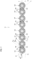
Fig. 1] Fig. 1 is a cross-sectional view showing an optical fiber ribbon according to a first embodiment, - [
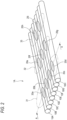
Fig. 2] Fig. 2 is a perspective view of the optical fiber ribbon shown inFig. 1 , - [
Fig. 3] Fig. 3 is a diagram illustrating a manufacturing method of the optical fiber ribbon, - [
Fig. 4] Fig. 4 is a diagram illustrating a step of applying a resin, - [
Fig. 5] Fig. 5 a diagram showing how the resin is applied to the optical fiber, and - [
Fig. 6] Fig. 6 is a cross-sectional view showing an optical fiber ribbon according to a second embodiment. - An optical fiber ribbon is sometimes used by being housed in an optical fiber cable. A force is applied so as to bend to roll the optical fiber ribbon up in a cross-sectional direction perpendicular to a longitudinal direction during being stored in the optical fiber cable. Therefore, when the optical fiber ribbon is rolled up, there is a possibility that an adhesive portion coupling the optical fibers is broken.
- In the case of the optical fiber ribbon described in Patent Literature 1, since the same amount of adhesive member is applied on both the upper surface side and the lower surface side, there is a high possibility that breaking of the adhesive member or peeling between the adhesive member and the optical fibers occur on the bent outside, and the optical fiber ribbon disassembles.
- In the case of the optical fiber ribbons described in
Patent Literatures 2 and 3, since the adhesive resin is applied only on one side, there is a high possibility that when the optical fiber ribbon is bent, the adhesive resin is broken or peeling between the adhesive resin and the optical fibers occurs, and the optical fiber ribbon disassembles. - In the case of the optical fiber ribbon described in
Patent Literature 4, since the second adhesive portion protrudes from the tangent line passing through the front surfaces of the optical fibers, a cross-sectional area of the optical fiber ribbon increases, and the optical fiber ribbon cannot be housed in the optical fiber cable at high density. - An object of the present disclosure is to provide an optical fiber ribbon and a sub-ribbon-type optical fiber ribbon that can prevent breaking of an adhesive resin coupling optical fibers and that can be housed in an optical fiber cable at high density.
- According to the present disclosure, an optical fiber ribbon and a sub-ribbon-type optical fiber ribbon that can prevent breaking of a resin coupling optical fibers and that can be housed in an optical fiber cable at high density can be provided.
- First, embodiments of the present disclosure are listed and described. An optical fiber ribbon according to an aspect of the present disclosure is (1) an intermittently coupled-type optical fiber ribbon, including: a plurality of optical fibers arranged in parallel; and intermittently coupling portions formed by coupling parts between the adjacent optical fibers with a resin, in which in the coupling portions, the resin is provided on one side surface and the other side surface of the optical fiber ribbon, when an average of maximum values of thicknesses TF of the coupling portions on the one side surface is set as TFave and an outer diameter of each optical fiber is set as D, D/4 ≤ TFave ≤ D/2, and when an average of maximum values of thicknesses TB of the coupling portions on the other side surface is set as TBave, TBave < TFave. According to this configuration, when a force is applied so as to bend to roll the optical fiber ribbon up in a cross-sectional direction perpendicular to a longitudinal direction during being stored in an optical fiber cable, since a resin amount on a first surface and a resin amount on a second surface are different, breaking of the resin or peeling between the resin and the optical fibers can be made less likely to occur. Therefore, a risk of the optical fiber ribbon disassembling is reduced, and the optical fiber ribbon can be easily rolled up and stored in the optical fiber cable. In addition, since the resin does not protrude from a tangent line passing through front surfaces of the optical fibers, a ribbon cross-sectional area can be prevented from becoming large, and the optical fiber ribbon can be housed in the optical fiber cable at high density.
- In addition, a sub-ribbon-type optical fiber ribbon according to an aspect of the present disclosure is (2) a sub-ribbon-type optical fiber ribbon, including: at least two sub-ribbons each including a plurality of optical fibers arranged in parallel and a first coupling portion formed by coupling the adjacent optical fibers with a resin; and intermittently second coupling portions formed by coupling parts bewteen the adjacent sub-ribbons with the resin, in which in the second coupling portions, the resin is provided on one side surface and the other side surface of the sub-ribbon-type optical fiber ribbon, when an average of maximum values of thicknesses TF1 of the second coupling portions on the one side surface is set as TF1ave and an outer diameter of each optical fiber is set as D, D/4 ≤ TF1ave ≤ D/2, and when an average of maximum values of thicknesses TB1 of the second coupling portions on the other side surface is set as TB1ave, TB1ave < TF1ave. According to this configuration, when the sub-ribbons are coupled, a force is applied so as to bend to roll the optical fiber ribbon up in a cross-sectional direction during being stored in an optical fiber cable, and in this case, since resin amounts are different on both surfaces, breaking of the resin or peeling between the resin and the sub-ribbons can be less likely to occur. Therefore, a risk of the optical fiber ribbon disassembling is reduced, and the optical fiber ribbon can be easily rolled up and stored in the optical fiber cable. In addition, since the resin does not protrude from a tangent line passing through front surfaces of the optical fibers, a ribbon cross-sectional area can be prevented from becoming large, which is advantageous for densification of the optical fiber cable.
- (3) The outer diameter D may be 210 µm or less. According to this configuration, the densification of the optical fiber cable can be further realized by using the optical fiber having a small diameter of 210 µm or less.
- Specific examples of the optical fiber ribbon and the sub-ribbon-type optical fiber ribbon according to the embodiments of the present disclosure will be described below with reference to the drawings. The present invention is not limited to these exemplifications, but is indicated by the scope of claims, and is intended to include all modifications within a scope and meaning equivalent to the scope of claims.
-
Fig. 1 is a cross-sectional view of anoptical fiber ribbon 1A according to a first embodiment.Fig. 2 is a perspective view of theoptical fiber ribbon 1A.Fig. 1 is a cross-sectional view taken along a line A-A ofFig. 2 . As shown inFigs. 1 and2 , theoptical fiber ribbon 1A includes a plurality of optical fibers 10 (10A to 10H in the present embodiment), and a plurality of coupling portions 20 (20a to 20i in the present embodiment) that couples the optical fibers 10. In the present embodiment, the eightoptical fibers 10A to 10H and the ninecoupling portions 20a to 20i that couple the optical fibers 10 are provided. - The eight
optical fibers 10A to 10H are arranged in parallel in a direction crossing a longitudinal direction of the optical fibers. The ninecoupling portions 20a to 20i are provided intermittently in the longitudinal direction and a width direction of theoptical fibers 10A to 10H arranged in parallel. That is, theoptical fiber ribbon 1A is an intermittently coupled-type optical fiber ribbon including thecoupling portions 20a to 20i that intermittently couple parts of theoptical fibers 10A to 10H in the longitudinal direction and the width direction. - The optical fiber 10 includes, for example, a
glass fiber 11 including a core and a cladding, and twocoating layers glass fiber 11. Theinner coating layer 12 of the two coating layers is made of a cured product of a primary resin. Theouter coating layer 13 of the two coating layers is made of a cured product of a secondary resin. An outer diameter of thecoating layer 13 made of the secondary resin, that is, an outer diameter D of each optical fiber 10 is, for example, 210 µm or less. The optical fiber cable 10 may have a colored layer on the outermost circumference. - In the primary resin constituting the
inner coating layer 12 being in contact with theglass fiber 11, a soft resin having a relatively low Young's modulus is used as a buffer layer. In addition, in the secondary resin constituting theouter coating layer 13, a hard resin having a relatively high Young's modulus is used as a protective layer. The cured product of the secondary resin has a Young's modulus of 900 Mpa or higher, preferably 1000 MPa or higher, and more preferably 1500 MPa or higher at a room temperature (for example, 23°C). - The
coupling portions 20a to 20i are provided on both a front surface side (upper side inFig. 1 ) and a back surface side (lower side inFig. 1 ) of a ribbon surface formed by theoptical fibers 10A to 10H arranged in parallel. Thecoupling portions 20a to 20i includefront coupling portions 21a to 21i provided on the front surface side andback coupling portions 22a to 22i provided on the back surface side. Thefront coupling portions 21a to 21i and theback coupling portions 22a to 22i are paired and provided at the same positions on the front side and the back side between the optical fibers. - The
coupling portions 20a to 20i are arranged in the width direction of theoptical fiber ribbon 1A, that is, in a parallel direction of theoptical fibers 10A to 10H. For example, in asplice region 31 shown inFig. 2 , thecoupling portion 20a between theoptical fibers coupling portion 20b between theoptical fibers coupling portion 20c between theoptical fibers coupling portion 20d between theoptical fibers splice region 32, thecoupling portion 20e between theoptical fibers coupling portion 20f between theoptical fibers coupling portion 20g between theoptical fibers splice region 33, thecoupling portion 20h between theoptical fibers coupling portion 20i between theoptical fibers - The
coupling portion 20 is, for example, made of a resin material such as an acrylic ultraviolet curable resin or an epoxy ultraviolet curable resin. A Young's modulus of a cured product of the resin constituting thecoupling portion 20 is 0.5 MPa or more and 200 MPa or less at the room temperature (for example, 23°C). Thecoupling portion 20 may be made of a resin containing, for example, a silicone lubricant. - In this way, in the
optical fiber ribbon 1A, thecoupling portion 20 where the optical fibers are coupled to each other is implemented by the part coated with the resin, and a non-coupling portion where the optical fibers are not coupled to each other is implemented by a part where the resin is not applied. - The
front coupling portions 21a to 21i provided on the front surface (upper surface) side of theoptical fiber ribbon 1A do not protrude upward from a virtual straight line Pf passing through front surfaces of theoptical fibers 10A to 10H. Theback coupling portions 22a to 22i provided on the back surface (lower surface) side of theoptical fiber ribbon 1A do not protrude downward from a virtual straight line Pb passing through back surfaces of theoptical fibers 10A to 10H. - Specifically, the four
front coupling portions 21a to 21d included in thesplice region 31 are formed such that when a virtual plane H formed by connecting centers of theoptical fibers 10A to 10H arranged in parallel is set as a reference position, and an average of thicknesses TFmax from the virtual plane H to highest points of thefront coupling portions 21a to 21d is set as TFave, TFave satisfies D/4 ≤ TFave ≤ D/2 with respect to the outer diameter D of the optical fiber 10. The three front coupling portions 21e to 21g included in thesplice region 32 are also formed such that an average TFave of thicknesses TFmax from the virtual plane H to highest points of the front coupling portions 21e to 21g satisfies D/4 ≤ TFave ≤ D/2. The two front coupling portions 21h and 21i included in thesplice region 33 are also formed such that an average TFave of thicknesses TFmax from the virtual plane H to highest points of the front coupling portions 21h and 21i satisfies D/4 ≤ TFave ≤ D/2. In this way, for each of thesplice regions Fig. 2 , thefront coupling portions 21a to 21i are formed such that the average TFave of the thicknesses TFmax of thefront coupling portions 21a to 21i satisfies D/4 ≤ TFave ≤ D/2. - Furthermore, the four
back coupling portions 22a to 22d included in thesplice region 31 are formed such that when an average of thicknesses TBmax from the virtual plane H to lowest points of theback coupling portions 22a to 22d is set as TBave, TBave satisfies TBave < TFave with respect to the thickness average TFave of thefront coupling portions 21a to 21d of thesplice region 31. The three back coupling portions 22e to 22g included in thesplice region 32 are formed such that when an average TBave of thicknesses TBmax from the virtual plane H to lowest points of the back coupling portions 22e to 22g satisfies TBave < TFave with respect to the thickness average TFave of the front coupling portions 21e to 21g of thesplice region 32. The two back coupling portions 22h and 22i included in thesplice region 33 are formed such that when an average TBave of thicknesses TBmax from the virtual plane H to lowest points of the back coupling portions 22h and 22i satisfies TBave < TFave with respect to the thickness average TFave of the front coupling portions 21h and 21i of thesplice region 33. - The average of the maximum values of the thicknesses TF of all the
front coupling portions 21a to 21i may be calculated as TFave based on the average of the maximum thicknesses of the front coupling portions for each of thesplice regions back coupling portions 22a to 22i may be calculated as TBave based on the average of the maximum thicknesses of the back coupling portions for each of thesplice regions front coupling portions 21a to 21i satisfies D/4 ≤ TFave ≤ D/2, and the individual thicknesses TF of some of thefront coupling portions 21a to 21i do not have to satisfy D/4 ≤ TF ≤ D/2. Similarly, it is sufficient that the average TBave of the maximum values of the thicknesses TB of theback coupling portions 22a to 22i satisfies TBave < TFave, and the individual thicknesses TB of some of theback coupling portions 22a to 22i do not have to satisfy TB < TF. - Next, a manufacturing method of the
optical fiber ribbon 1A will be described with reference toFigs. 3 to 5 . As shown inFig. 3 , theoptical fibers 10A to 10H are closely arranged in an up-down direction in a vertical line. Theoptical fibers 10A to 10H are drawn out from drawing-out bobbins at predetermined intervals such that timings for arranging the optical fibers are shifted to make the number of the optical fibers arranged in the vertical line two, three, four, ..., and eight in order. - The
optical fiber 10A drawn out from a drawing-outbobbin 51a and theoptical fiber 10B drawn out from a drawing-outbobbin 51b are arranged in the up-down direction so as to be in close contact with each other at an adhesive position P1. Next, theoptical fiber 10C drawn out from a drawing-outbobbin 51c is arranged in the up-down direction so as to be in close contact with theoptical fiber 10B immediately above at an adhesive position P2. Next, theoptical fiber 10D drawn out from a drawing-outbobbin 51d is arranged in the up-down direction so as to be in close contact with theoptical fiber 10C immediately above at an adhesive position P3. Although the illustration is omitted, theoptical fibers 10E to 10H are similarly arranged in the up-down direction so as to be in close contact with the adjacentoptical fibers 10D to 10G immediately above at adhesive positions P4 to P7. - Adhesive means for adhering the optical fibers that are in close contact with each other in the up-down direction with the resin constituting the
coupling portions 20 is provided at each of the adhesive positions P1, P2, and P3. As the adhesive means, for example,resin supply devices 54a to 54c including syringe pairs 52a to 52c that supply the resin for forming thecoupling portions 20, anddispensers 53a to 53c that control a supply amount of the resin are provided.Ultraviolet irradiation devices 55a to 55c that cure the resin are provided at subsequent stages of theresin supply devices 54a to 54c. - As shown in
Figs. 4 and 5 , resins 57 can be applied dropwise by the syringe needle pairs 56 (56a to 56c), and it is desirable that theresins 57 adhere between the optical fibers 10 by surface tension and do not drip easily. It is preferable that theresin 57 has a viscosity of 1 Pa·S to 10 Pa·S at 25°C, for example. The syringe needle pairs 56a to 56c are arranged on both sides of the two optical fibers 10 arranged in close contact with each other in the up-down direction, and can apply theresins 57 toward the close contact portions between the two optical fibers. - The
optical fiber ribbon 1A produced in this way is wound on a winding-upbobbin 58. - As described above, the
optical fiber ribbon 1A is the intermittently coupled-type optical fiber ribbon including the plurality ofoptical fibers 10A to 10H arranged in parallel, and the intermittently couplingportions 20a to 20i formed by coupling parts between the adjacent optical fibers with the resin. In thecoupling portions 20a to 20i, the resin is provided on both the front surface (example of one side surface) and the back surface (example of the other side surface) of theoptical fiber ribbon 1A, when the average of the maximum values of the thicknesses TF of thefront coupling portions 21a to 21i is set as TFave and the outer diameter of theoptical fibers 10A to 10H is set as D, D/4 ≤ TFave ≤ D/2, and when the average of the maximum values of the thicknesses TB of theback coupling portions 22a to 22i is set as TBave, TBave < TFave. According to this configuration, when theoptical fiber ribbon 1A is stored in the optical fiber cable, a force is applied to bend theoptical fiber ribbon 1A in a cross-sectional direction perpendicular to the longitudinal direction, and in this case, since the resin amounts (thicknesses TF and thicknesses TB) of thecoupling portions 20 provided on both the front side and the back side of theoptical fiber ribbon 1A are different, for example, by arranging thefront coupling portions 21a to 21i, which are thicker, on the bent outside, breaking of the resin or peeling between the resin and the optical fibers can be less likely to occur. Therefore, theoptical fiber ribbon 1A does not disassemble, and theoptical fiber ribbon 1A can be easily rolled up, so that storability of theoptical fiber ribbon 1A in the optical fiber cable can be improved. In addition, since the resin constituting both thefront coupling portions 21a to 21i and theback coupling portions 22a to 22i does not protrude from a tangent line passing through the front surfaces of theoptical fibers 10A to 10H, a cross-sectional area of theoptical fiber ribbon 1A can be prevented from becoming large, and theoptical fiber ribbon 1A can be stored in the optical fiber cable at high density. - Further, according to the
optical fiber ribbon 1A, the densification of the optical fiber cable can be further realized by using the thinoptical fibers 10A to 10H having the outer diameter D of 210 µm or less. - In the above embodiment, the optical fiber ribbon including the eight optical fibers is taken as an example, and the present invention is not limited thereto. For example, the optical fiber ribbon may be an optical fiber ribbon including multiples of four optical fibers, such as twelve or twenty-four optical fibers.
- Next, an embodiment of the
optical fiber ribbon 1A configured as described above will be described with reference to Table 1. As shown in Table 1, variousoptical fiber ribbons 1A shown in No. 1 to No. 11 are produced, in which TFave, which is the average of the maximum thicknesses TFmax of thefront coupling portions 21a to 21i, and TBave, which is the average of the maximum thicknesses TBmax of theback coupling portions 22a to 22i, are changed, and in the variousoptical fiber ribbons 1A shown in No. 1 to No. 11, resistance to disassembly, storability of cable, and densification during being stored in the optical fiber cable are evaluated.[Table 1] Sample number No. 1 No. 2 No. 3 No. 4 No. 5 No. 6 No. 7 No. 8 No. 9 No. 10 No. 11 Thickness TF (µm) of front coupling portion 40 50 50 50 75 75 75 100 100 100 120 Thickness TB (µm) of back coupling portion 40 50 40 0 75 50 0 100 75 0 120 Resistance to disassembly C A A C A A C A A C A Storability of cable B B A A B A A B A A B Densificatio n A A A A A A A A A A C - As shown in Table 1, in the optical fiber ribbon of No. 1, the thickness TFave of the front coupling portions and the thickness TBave of the back coupling portions are set to the same thicknesses of 40 µm. In the optical fiber ribbons of No. 2 to No. 4, the thicknesses TFave of the front coupling portions are all set to 50 µm, and the thicknesses TBave of the back coupling portions are set to 50 µm for No. 2, 40 µm for No. 3, and 0 µm for No. 4. In the optical fiber ribbons of No. 5 to No. 7, the thicknesses TFave of the front coupling portions are all set to 75 µm, and the thicknesses TBave of the back coupling portions are set to 75 µm for No. 5, 50 µm for No. 6, and 0 µm for No. 7. In the optical fiber ribbons of No. 8 to No. 10, the thicknesses TFave of the front coupling portions are all set to 100 µm, and the thicknesses TBave of the back coupling portions are set to 100 µm for No. 8, 75 µm for No. 9, and 0 µm for No. 10. In the optical fiber ribbon of No. 11, the thickness TFave of the front coupling portions and the thickness TBave of the back coupling portions are set to the same thicknesses of 120 µm. The outer diameter D of each of the optical fibers constituting each optical fiber ribbon is set to 200 µm. Therefore, D/4 = 50 µm and D/2 = 100 µm.
- In a case where the optical fiber ribbon is spread in the width direction at the non-coupling portion where the resin is not applied, and is spread by 60% of a length of the non-coupling portion (interval between adjacent coupling portions), the "resistance to disassembly" is evaluated as "A" when the optical fibers do not peel from the coupling portion, and is evaluated as "C" when the optical fibers peel from the coupling portion. Ease of rolling the optical fiber ribbon up when the thickness TFave of the front coupling portion and the thickness TBave of the back coupling portion are the same is compared, and the "storability of cable" is evaluated as "A" when the optical fiber ribbon is more easily rolled up, and is evaluated as "B" when the ease of rolling the optical fiber ribbon up is the same. In terms of comparison of cross-sectional areas of the optical fiber ribbons, the "densification" is evaluated as "A" when the optical fiber ribbon with the thickness of 100 µm or less at the coupling portions is determined as an optical fiber ribbon with a small cross-sectional area and suitable for the densification, and is evaluated as "C" when the optical fiber ribbon with the thickness of more than 100 µm at the coupling portions is determined to be unsuitable for the densification.
- In the case of the optical fiber ribbon of No. 1 in which the coupling portions having the thicknesses of less than 50 µm are provided on both the front surface side and the back surface side, adhesion areas between the coupling portions and the optical fibers are small, and adhesion between the coupling portions and the optical fibers is not sufficiently exhibited, and thus, the resistance to disassembly is evaluated as "C". In the case of the optical fiber ribbons of No. 4, No. 7, and No 10 which are not provided with the back coupling portions (no resin is applied to the back surface side), adhesion between the optical fibers and the coupling portions is not sufficiently exhibited by the front coupling portions alone, and thus, the resistance to disassembly is evaluated as "C". In the case of the optical fiber ribbons of NO. 2, No. 3, No. 5, No. 6, No. 8, No. 9, and No. 11 which have the thicknesses TFave of 50 µm or more at the front coupling portion and the thicknesses TBave of the back coupling portions of 40 µm or more, sufficient adhesion areas are secured between the coupling portions and the optical fibers, and the adhesion between the coupling portions and the optical fibers is sufficiently exhibited, and thus, the resistance to disassembly is evaluated as "A".
- Compared to the optical fiber ribbons having the same thicknesses at the coupling portions on the front surface side and the back surface side, the optical fiber ribbons of No. 3, No. 4, No. 6, No. 7, No. 9, and No. 10 whose thicknesses TFave of the front coupling portions are different from the thicknesses TBave of the back coupling portions are easily rolled up, and thus, the storability of cable is evaluated as "A". In the case of the optical fiber ribbons of No. 1, No. 2, No. 5, No. 8, and No. 11, the thickness TFave of the front coupling portions and the thickness TBave of the back coupling portions are the same thicknesses, and thus, compared to the optical fiber ribbon whose thickness TFave of the front coupling portions is different from the thickness TBave of the back coupling portions, the optical fiber ribbons of No. 1, No. 2, No. 5, No. 8, and No. 11 are slightly difficult to be rolled up, and the storability of cable is evaluated as "B".
- In the case of the optical fiber ribbons of No. 1 to No. 10, the thickness TFave of the front coupling portions and the thickness TBave of the back coupling portions are both 100 µm or less, that is, equal to or less than the outer diameter D of the optical fibers, and thus, the densification is evaluated as "A". In the case of the optical fiber ribbon of No. 11, the thickness TFave of the front coupling portions and the thickness TBave of the back coupling portions both exceed 100 µm, that is, the coupling portions protrude from the front surfaces of the optical fibers, and thus, it cannot be said that the optical fiber ribbon is suitable for the densification due to the large cross-sectional area, and the densification is evaluated as "C".
- From the above evaluation results, it can be confirmed that the optical fiber ribbons of No. 3, No. 6, and No. 9 are evaluated as "A" in the three evaluation items of the "resistance to disassembly", the "storability of cable", and the "densification". Then, it is confirmed that as the configurations, the coupling portions provided on the front side of the optical fiber ribbon and on the back side thereof have to satisfy the conditions of D/4 ≤ TFave ≤ D/2 and TBave < TFave.
-
Fig. 6 is a cross-sectional view of anoptical fiber ribbon 1B according to a second embodiment. As shown inFig. 6 , theoptical fiber ribbon 1B includes a plurality (four in the present embodiment) of sub-ribbons 100 (100A to 100D in the present embodiment), and a plurality of coupling portions 120 (120a to 20b in the present embodiment) that couples the sub-ribbons 100. - Each sub-ribbon 100 includes two optical fibers 110. For example, the
sub-ribbon 100A includesoptical fibers optical fibers coating resin 115a (example of the first coupling portion). The sub-ribbon 100B includesoptical fibers optical fibers coating resin 115b (example of the first coupling portion). The sub-ribbon 100C includesoptical fibers optical fibers coating resin 115c (example of the first coupling portion). Thesub-ribbon 100D includesoptical fibers optical fibers coating resin 115d (example of the first coupling portion). An outer diameter D of each of theoptical fibers 110A to 110H is, for example, 210 µm or less. - The
coupling portion 120a (example of the second coupling portion) is provided between the sub-ribbons 100A and 100B. Thecoupling portion 120b (example of the second coupling portion) is provided between the sub-ribbons 100C and 100D. Thecoupling portion 120a and thecoupling portion 120b are arranged in parallel in a width direction of theoptical fiber ribbon 1B. Thecoupling portions front coupling portions optical fiber ribbon 1B andback coupling portions front coupling portions back coupling portions - In the cross-sectional view shown in
Fig. 6 , the twocoupling portions optical fiber ribbon 1B are, for example, similarly to those in theoptical fiber ribbon 1A shown inFig. 2 , intermittently provided in a longitudinal direction and the width direction of the sub-ribbons 100A to 100D arranged in parallel. Theoptical fiber ribbon 1B is an intermittently coupled-type and sub-ribbon-type optical fiber ribbon including the coupling portions 120 that couples parts of the sub-ribbons in the longitudinal direction and the width direction of the sub-ribbons 100A to 100D. - The
front coupling portions Fig. 6 ) of theoptical fibers 110A to 110H. Theback coupling portions optical fiber ribbon 1B do not protrude downward from a straight line Pb passing through back surfaces (lower surfaces inFig. 6 ) of theoptical fibers 110A to 110H. - For example, when a virtual plane H formed by connecting centers of the
optical fibers 110A to 110H arranged in parallel is set as a reference position, and an average of thicknesses TF1max from the virtual plane H to highest points of thefront coupling portions back coupling portions optical fiber ribbon 1B, as in the case of the first embodiment. - As described above, the
optical fiber ribbon 1B according to the second embodiment is the sub-ribbon-type optical fiber ribbon including the sub-ribbons 100A to 100D including the plurality ofoptical fibers 110A to 110H arranged in parallel, and thecoating resins 115a to 115d (examples of the first coupling portions) formed by coupling the adjacent optical fibers with the resin. Theoptical fiber ribbon 1B intermittently includes thecoupling portions coupling portions optical fiber ribbon 1B. Then, when the average of the maximum values of the thicknesses TF1 of thefront coupling portions optical fibers 110A to 110H is set as D, D/4 ≤ TF1ave ≤ D/2, and when the average of the maximum values of the thicknesses TB1 of theback coupling portions optical fiber ribbon 1A of the first embodiment can be obtained. - In the above second embodiment, the sub-ribbon including the two optical fibers is taken as an example, and the number of optical fibers constituting the sub-ribbon may be a predetermined number of two or more. The sub-ribbon may be an intermittently-coupled sub-ribbon intermittently having coupling portions and non-coupling portions in the longitudinal direction or width direction of the optical fibers.
- Although the present disclosure has been described in detail and with reference to the specific embodiments, it will be apparent to those skilled in the art that various changes and modifications can be made without departing from the spirit and scope of the present disclosure. In addition, the number, positions, shapes, and the like of the constituent members described above are not limited to those in the above embodiment, and can be changed to suitable numbers, positions, shapes, and the like in carrying out the present disclosure.
-
- 1A, 1B: optical fiber ribbon
- 10 (10A to 10H): optical fiber
- 11: glass fiber
- 12: coating layer (primary resin)
- 13: coating layer (secondary resin)
- 20 (20a to 20i): coupling portion
- 21a to 21i: front coupling portion
- 22a to 22i: back coupling portion
- 31 to 33: splice region
- 51a to 51d: bobbin
- 52a to 52c: syringe pair
- 53a to 53c: dispenser
- 54a to 54c: resin supply device
- 55a to 55c: ultraviolet irradiation device
- 56 (56a, 56b): syringe needle pair
- 57: resin
- 58: winding-up bobbin
- 100 (100A to 100D): sub-ribbon
- 110 (110A to 110H): optical fiber
- 115a to 115d: coating resin (example of first coupling portion)
- 120 (120a, 120b): coupling portion (example of second coupling portion)
- 121a, 121b: front coupling portion
- 122a, 122b: back coupling portion
- D: outer diameter of optical fiber
- TF, TB: thickness of coupling portion
- H: virtual plane
- P1 to P3: adhesive position
- Pf, Pb: virtual straight line
Claims (4)
- An intermittently coupled-type optical fiber ribbon, comprising:a plurality of optical fibers arranged in parallel; andintermittently coupling portions formed by coupling parts between the adjacent optical fibers with a resin, whereinin the coupling portions, the resin is provided on one side surface and the other side surface of the optical fiber ribbon,when an average of maximum values of thicknesses TF of the coupling portions on the one side surface is set as TFave and an outer diameter of each optical fiber is set as D, D/4 ≤ TFave ≤ D/2, andwhen an average of maximum values of thicknesses TB of the coupling portions on the other side surface is set as TBave, TBave < TFave.
- The optical fiber ribbon according to claim 1, wherein
the outer diameter D is 210 µm or less. - A sub-ribbon-type optical fiber ribbon, comprising:at least two sub-ribbons each including a plurality of optical fibers arranged in parallel and a first coupling portion formed by coupling the adjacent optical fibers with a resin; andintermittently second coupling portions formed by coupling parts between the adjacent sub-ribbons with the resin, whereinin the second coupling portions, the resin is provided on one side surface and the other side surface of the sub-ribbon-type optical fiber ribbon,when an average of maximum values of thicknesses TF1 of the second coupling portions on the one side surface is set as TF1ave and an outer diameter of each optical fiber is set as D, D/4 ≤ TF1ave ≤ D/2, andwhen an average of maximum values of thicknesses TB1 of the second coupling portions on the other side surface is set as TB1ave, TB1av, < TF1ave.
- The sub-ribbon-type optical fiber ribbon according to claim 3, wherein
the outer diameter D is 210 µm or less.
Applications Claiming Priority (2)
| Application Number | Priority Date | Filing Date | Title |
|---|---|---|---|
| JP2020155584 | 2020-09-16 | ||
| PCT/JP2021/033606 WO2022059654A1 (en) | 2020-09-16 | 2021-09-13 | Optical fiber ribbon and sub-tape-type optical fiber ribbon |
Publications (2)
| Publication Number | Publication Date |
|---|---|
| EP4215965A1 true EP4215965A1 (en) | 2023-07-26 |
| EP4215965A4 EP4215965A4 (en) | 2024-03-06 |
Family
ID=80776664
Family Applications (1)
| Application Number | Title | Priority Date | Filing Date |
|---|---|---|---|
| EP21869341.4A Pending EP4215965A4 (en) | 2020-09-16 | 2021-09-13 | Optical fiber ribbon and sub-tape-type optical fiber ribbon |
Country Status (4)
| Country | Link |
|---|---|
| US (1) | US12379558B2 (en) |
| EP (1) | EP4215965A4 (en) |
| JP (1) | JP7750243B2 (en) |
| WO (1) | WO2022059654A1 (en) |
Families Citing this family (3)
| Publication number | Priority date | Publication date | Assignee | Title |
|---|---|---|---|---|
| WO2023003056A1 (en) * | 2021-07-21 | 2023-01-26 | 엘에스전선 주식회사 | Optical fiber ribbon |
| CN115144956B (en) * | 2022-09-06 | 2022-11-04 | 江苏中天科技股份有限公司 | A flexible optical fiber ribbon and ribbon optical cable |
| CN115144957B (en) * | 2022-09-06 | 2022-11-04 | 江苏中天科技股份有限公司 | A kind of orientable winding flexible optical fiber ribbon and optical fiber cable thereof |
Family Cites Families (11)
| Publication number | Priority date | Publication date | Assignee | Title |
|---|---|---|---|---|
| WO2003100495A1 (en) | 2002-05-28 | 2003-12-04 | Sumitomo Electric Industries, Ltd. | Optical fiber tape core |
| JP6329912B2 (en) | 2015-01-19 | 2018-05-23 | 古河電気工業株式会社 | Optical fiber ribbon, optical fiber cable |
| US10514517B2 (en) * | 2015-07-31 | 2019-12-24 | Sumitomo Electric Industries, Ltd. | Optical fiber cable |
| JP6569429B2 (en) | 2015-09-25 | 2019-09-04 | 住友電気工業株式会社 | Optical fiber ribbon |
| JP6188097B2 (en) | 2016-05-20 | 2017-08-30 | 日本電信電話株式会社 | Intermittently bonded optical fiber tape and optical cable using the same |
| WO2018022031A1 (en) | 2016-07-27 | 2018-02-01 | Prysmian S.P.A. | Flexible optical-fiber ribbon |
| JP2019049617A (en) | 2017-09-08 | 2019-03-28 | 住友電気工業株式会社 | Optical fiber ribbon and method of manufacturing optical fiber ribbon |
| JP2020155584A (en) | 2019-03-20 | 2020-09-24 | 東レKpフィルム株式会社 | Electromagnetic wave shield film, and manufacturing method thereof |
| US11131817B2 (en) | 2019-05-09 | 2021-09-28 | Go!Foton Holdings, Inc. | Multi-fiber cable |
| CN111175887A (en) * | 2020-02-13 | 2020-05-19 | 江苏亨通光电股份有限公司 | Optical fiber ribbon, optical cable, and method for manufacturing optical fiber ribbon |
| JP7084449B2 (en) | 2020-07-10 | 2022-06-14 | 古河電気工業株式会社 | Optical fiber tape core wire, optical fiber cable |
-
2021
- 2021-09-13 US US18/245,587 patent/US12379558B2/en active Active
- 2021-09-13 JP JP2022550556A patent/JP7750243B2/en active Active
- 2021-09-13 EP EP21869341.4A patent/EP4215965A4/en active Pending
- 2021-09-13 WO PCT/JP2021/033606 patent/WO2022059654A1/en not_active Ceased
Also Published As
| Publication number | Publication date |
|---|---|
| WO2022059654A1 (en) | 2022-03-24 |
| JP7750243B2 (en) | 2025-10-07 |
| JPWO2022059654A1 (en) | 2022-03-24 |
| US20230367088A1 (en) | 2023-11-16 |
| US12379558B2 (en) | 2025-08-05 |
| EP4215965A4 (en) | 2024-03-06 |
Similar Documents
| Publication | Publication Date | Title |
|---|---|---|
| EP4215965A1 (en) | Optical fiber ribbon and sub-tape-type optical fiber ribbon | |
| EP0922980B1 (en) | Bonded array of transmission media | |
| CN111033342A (en) | High optical fiber density ribbon cable | |
| EP0953857B1 (en) | Optical Fiber | |
| US6600859B2 (en) | Composite modular optical fiber ribbon | |
| US20010007604A1 (en) | Fiber optic cable with profiled group of optical fibers | |
| CN110058364A (en) | Fibre ribbon | |
| US11415769B2 (en) | Intermittent connection-type optical fiber tape core wire, optical fiber cable, and method for manufacturing intermittent connection-type optical fiber tape core wire | |
| CA1203062A (en) | Optical fibre ribbon structure | |
| CN116027479B (en) | A discontinuously reinforced optical fiber ribbon, a preparation method thereof, and an optical fiber ribbon cable | |
| US20230393350A1 (en) | Optical fiber ribbon and method for manufacturing optical fiber ribbon | |
| KR20070010148A (en) | Fiber Optic Tape Units and Fiber Optic Cables | |
| JPH09113773A (en) | Optical fiber ribbon | |
| US7397990B2 (en) | Signal transmitting cable | |
| CN113678044A (en) | Optical fiber ribbon core wire, mold and method for manufacturing optical fiber ribbon core wire | |
| EP4266100A1 (en) | Optical fiber ribbon | |
| JP2002341208A (en) | Optical fiber ribbon and optical fiber cable | |
| JP3022710B2 (en) | Thin optical fiber unit for optical composite ground wire and method of manufacturing the same | |
| JP2003107306A (en) | Optical fiber ribbon and manufacturing method thereof | |
| US20240176087A1 (en) | Optical fiber ribbon with a passive layer | |
| US12326606B2 (en) | Optical-fiber ribbon, die, and method of manufacturing optical-fiber ribbon | |
| EP4556977A1 (en) | Optical fiber ribbon and optical cable | |
| JPH02289804A (en) | optical fiber unit | |
| JPH1010379A (en) | High strength optical fiber cord | |
| JPH11311726A (en) | Optical fiber ribbon |
Legal Events
| Date | Code | Title | Description |
|---|---|---|---|
| STAA | Information on the status of an ep patent application or granted ep patent |
Free format text: STATUS: THE INTERNATIONAL PUBLICATION HAS BEEN MADE |
|
| PUAI | Public reference made under article 153(3) epc to a published international application that has entered the european phase |
Free format text: ORIGINAL CODE: 0009012 |
|
| STAA | Information on the status of an ep patent application or granted ep patent |
Free format text: STATUS: REQUEST FOR EXAMINATION WAS MADE |
|
| 17P | Request for examination filed |
Effective date: 20230316 |
|
| AK | Designated contracting states |
Kind code of ref document: A1 Designated state(s): AL AT BE BG CH CY CZ DE DK EE ES FI FR GB GR HR HU IE IS IT LI LT LU LV MC MK MT NL NO PL PT RO RS SE SI SK SM TR |
|
| DAV | Request for validation of the european patent (deleted) | ||
| DAX | Request for extension of the european patent (deleted) | ||
| A4 | Supplementary search report drawn up and despatched |
Effective date: 20240206 |
|
| RIC1 | Information provided on ipc code assigned before grant |
Ipc: G02B 6/44 20060101AFI20240131BHEP |
|
| STAA | Information on the status of an ep patent application or granted ep patent |
Free format text: STATUS: EXAMINATION IS IN PROGRESS |
|
| 17Q | First examination report despatched |
Effective date: 20251204 |