EP4215899A1 - Dispositif d'inspection de la qualité de l'eau - Google Patents
Dispositif d'inspection de la qualité de l'eau Download PDFInfo
- Publication number
- EP4215899A1 EP4215899A1 EP20926373.0A EP20926373A EP4215899A1 EP 4215899 A1 EP4215899 A1 EP 4215899A1 EP 20926373 A EP20926373 A EP 20926373A EP 4215899 A1 EP4215899 A1 EP 4215899A1
- Authority
- EP
- European Patent Office
- Prior art keywords
- fluid
- cup
- examination device
- wave
- water examination
- Prior art date
- Legal status (The legal status is an assumption and is not a legal conclusion. Google has not performed a legal analysis and makes no representation as to the accuracy of the status listed.)
- Pending
Links
- XLYOFNOQVPJJNP-UHFFFAOYSA-N water Substances O XLYOFNOQVPJJNP-UHFFFAOYSA-N 0.000 title claims abstract description 69
- 238000007689 inspection Methods 0.000 title 1
- 239000012530 fluid Substances 0.000 claims abstract description 97
- 230000004308 accommodation Effects 0.000 claims abstract description 38
- 230000001678 irradiating effect Effects 0.000 claims abstract description 9
- 239000000126 substance Substances 0.000 claims abstract description 9
- 244000005700 microbiome Species 0.000 claims description 86
- 230000002123 temporal effect Effects 0.000 claims description 42
- 230000003321 amplification Effects 0.000 claims description 18
- 238000003199 nucleic acid amplification method Methods 0.000 claims description 18
- 238000000034 method Methods 0.000 claims description 12
- 230000003287 optical effect Effects 0.000 claims description 7
- 239000000463 material Substances 0.000 description 16
- 239000012535 impurity Substances 0.000 description 12
- 230000000739 chaotic effect Effects 0.000 description 8
- 238000010586 diagram Methods 0.000 description 8
- 238000005259 measurement Methods 0.000 description 6
- 230000003595 spectral effect Effects 0.000 description 6
- 230000001066 destructive effect Effects 0.000 description 5
- 230000000694 effects Effects 0.000 description 5
- 238000004458 analytical method Methods 0.000 description 3
- 238000000149 argon plasma sintering Methods 0.000 description 3
- 238000004891 communication Methods 0.000 description 3
- 230000007423 decrease Effects 0.000 description 3
- 241000894006 Bacteria Species 0.000 description 2
- 230000001580 bacterial effect Effects 0.000 description 2
- 238000012360 testing method Methods 0.000 description 2
- 241000238876 Acari Species 0.000 description 1
- GWEVSGVZZGPLCZ-UHFFFAOYSA-N Titan oxide Chemical compound O=[Ti]=O GWEVSGVZZGPLCZ-UHFFFAOYSA-N 0.000 description 1
- 239000000654 additive Substances 0.000 description 1
- 235000013361 beverage Nutrition 0.000 description 1
- 230000004071 biological effect Effects 0.000 description 1
- 239000011248 coating agent Substances 0.000 description 1
- 238000000576 coating method Methods 0.000 description 1
- 230000001427 coherent effect Effects 0.000 description 1
- 230000035622 drinking Effects 0.000 description 1
- 238000001914 filtration Methods 0.000 description 1
- 239000011521 glass Substances 0.000 description 1
- 238000003384 imaging method Methods 0.000 description 1
- 230000003834 intracellular effect Effects 0.000 description 1
- 239000007788 liquid Substances 0.000 description 1
- 239000008267 milk Substances 0.000 description 1
- 210000004080 milk Anatomy 0.000 description 1
- 235000013336 milk Nutrition 0.000 description 1
- 239000002105 nanoparticle Substances 0.000 description 1
- 239000002245 particle Substances 0.000 description 1
- 238000012545 processing Methods 0.000 description 1
- 238000011282 treatment Methods 0.000 description 1
Images


Classifications
-
- G—PHYSICS
- G01—MEASURING; TESTING
- G01N—INVESTIGATING OR ANALYSING MATERIALS BY DETERMINING THEIR CHEMICAL OR PHYSICAL PROPERTIES
- G01N21/00—Investigating or analysing materials by the use of optical means, i.e. using sub-millimetre waves, infrared, visible or ultraviolet light
- G01N21/17—Systems in which incident light is modified in accordance with the properties of the material investigated
- G01N21/47—Scattering, i.e. diffuse reflection
- G01N21/4788—Diffraction
-
- G—PHYSICS
- G01—MEASURING; TESTING
- G01N—INVESTIGATING OR ANALYSING MATERIALS BY DETERMINING THEIR CHEMICAL OR PHYSICAL PROPERTIES
- G01N33/00—Investigating or analysing materials by specific methods not covered by groups G01N1/00 - G01N31/00
- G01N33/18—Water
-
- G—PHYSICS
- G01—MEASURING; TESTING
- G01N—INVESTIGATING OR ANALYSING MATERIALS BY DETERMINING THEIR CHEMICAL OR PHYSICAL PROPERTIES
- G01N21/00—Investigating or analysing materials by the use of optical means, i.e. using sub-millimetre waves, infrared, visible or ultraviolet light
- G01N21/17—Systems in which incident light is modified in accordance with the properties of the material investigated
- G01N21/47—Scattering, i.e. diffuse reflection
- G01N21/49—Scattering, i.e. diffuse reflection within a body or fluid
- G01N21/51—Scattering, i.e. diffuse reflection within a body or fluid inside a container, e.g. in an ampoule
-
- G—PHYSICS
- G01—MEASURING; TESTING
- G01N—INVESTIGATING OR ANALYSING MATERIALS BY DETERMINING THEIR CHEMICAL OR PHYSICAL PROPERTIES
- G01N15/00—Investigating characteristics of particles; Investigating permeability, pore-volume, or surface-area of porous materials
- G01N15/02—Investigating particle size or size distribution
-
- G—PHYSICS
- G01—MEASURING; TESTING
- G01N—INVESTIGATING OR ANALYSING MATERIALS BY DETERMINING THEIR CHEMICAL OR PHYSICAL PROPERTIES
- G01N15/00—Investigating characteristics of particles; Investigating permeability, pore-volume, or surface-area of porous materials
- G01N15/10—Investigating individual particles
- G01N15/14—Electro-optical investigation, e.g. flow cytometers
-
- G—PHYSICS
- G01—MEASURING; TESTING
- G01N—INVESTIGATING OR ANALYSING MATERIALS BY DETERMINING THEIR CHEMICAL OR PHYSICAL PROPERTIES
- G01N21/00—Investigating or analysing materials by the use of optical means, i.e. using sub-millimetre waves, infrared, visible or ultraviolet light
- G01N21/84—Systems specially adapted for particular applications
- G01N21/85—Investigating moving fluids or granular solids
-
- G—PHYSICS
- G01—MEASURING; TESTING
- G01N—INVESTIGATING OR ANALYSING MATERIALS BY DETERMINING THEIR CHEMICAL OR PHYSICAL PROPERTIES
- G01N21/00—Investigating or analysing materials by the use of optical means, i.e. using sub-millimetre waves, infrared, visible or ultraviolet light
- G01N21/84—Systems specially adapted for particular applications
- G01N21/88—Investigating the presence of flaws or contamination
- G01N21/94—Investigating contamination, e.g. dust
-
- G—PHYSICS
- G01—MEASURING; TESTING
- G01N—INVESTIGATING OR ANALYSING MATERIALS BY DETERMINING THEIR CHEMICAL OR PHYSICAL PROPERTIES
- G01N21/00—Investigating or analysing materials by the use of optical means, i.e. using sub-millimetre waves, infrared, visible or ultraviolet light
- G01N21/17—Systems in which incident light is modified in accordance with the properties of the material investigated
- G01N21/47—Scattering, i.e. diffuse reflection
- G01N21/4788—Diffraction
- G01N2021/479—Speckle
-
- G—PHYSICS
- G01—MEASURING; TESTING
- G01N—INVESTIGATING OR ANALYSING MATERIALS BY DETERMINING THEIR CHEMICAL OR PHYSICAL PROPERTIES
- G01N21/00—Investigating or analysing materials by the use of optical means, i.e. using sub-millimetre waves, infrared, visible or ultraviolet light
- G01N21/17—Systems in which incident light is modified in accordance with the properties of the material investigated
- G01N21/47—Scattering, i.e. diffuse reflection
- G01N21/49—Scattering, i.e. diffuse reflection within a body or fluid
- G01N21/51—Scattering, i.e. diffuse reflection within a body or fluid inside a container, e.g. in an ampoule
- G01N2021/513—Cuvettes for scattering measurements
Definitions
- One or more embodiments of the present disclosure relate to a water examination device.
- a fluid such as water or beverage is supplied to a user through various treatments such as filtration.
- substances other than additives that are added in the fluid as necessary, for example, microorganisms, etc., should be removed and then the fluid is supplied to the user.
- microorganisms in the fluid may unintentionally proliferate due to circumstances such as contact with external air.
- the present disclosure provides a water examination device that examines water quality by detecting microorganisms in a fluid in real-time using a chaotic wave sensor.
- a water examination device includes: a main body; a cup accommodation unit formed inward from a surface of the main body such that a cup containing a fluid is accommodated therein; a wave source for irradiating a wave toward the cup accommodation unit; a detector for detecting a laser speckle generated when the irradiated wave is multiple-scattered in the fluid, at every time point set in advance; and a controller for estimating whether foreign substances exist in the fluid in real-time by using the detected laser speckle.
- a water examination device may examine water quality, by estimating whether there are microorganisms in a fluid and/or a concentration of microorganisms rapidly at low costs by using a change in a temporal correlation or a spatial correlation of laser speckles.
- a water examination device includes: a main body; a cup accommodation unit formed inward from a surface of the main body such that a cup containing a fluid is accommodated therein; a wave source for irradiating a wave toward the cup accommodation unit; a detector for detecting a laser speckle generated when the irradiated wave is multiple-scattered in the fluid, at every time point set in advance; and a controller for estimating whether foreign substances exist in the fluid in real-time by using the detected laser speckle.
- the cup accommodation unit may include: a bottom portion formed in the main body; and a wall portion extending from the bottom portion toward the surface of the main body and formed to surround at least a part of a side surface of a cup accommodated in the cup accommodation unit.
- an angle between the bottom portion and the wall portion may not be a right angle.
- the angle may range from 85° to 88°.
- the wall portion may be formed to have an annular shape and may be formed to be narrowed toward the surface of the main body.
- three or more support portions may protrude from the bottom portion.
- each of the three or more support portions and the cup may be in a point-contact with each other.
- the bottom portion or the wall portion may include a multi-scattering amplification region for amplifying a number of times that the wave irradiated from the wave source is multiple scattered in the fluid.
- the multi-scattering amplification region ay amplify the number of multiple scattering in the fluid by reflecting at least some of the wave emitted from the fluid onto the fluid.
- the controller may obtain a temporal correlation of the detected laser speckle by using the detected laser speckle, and may estimate whether microorganisms exist in the fluid in real-time based on the obtained temporal correlation.
- the temporal correlation may include a difference between first image information of the laser speckle detected at a first time point and second image information of the laser speckle detected at a second time point that is different from the first time point.
- the first image information and the second image information may include at least one of pattern information of the laser speckle and intensity information of the wave.
- the controller may obtain a spatial correlation of an interference pattern of an optical image detected by the detector, and determine whether microorganisms exist in the fluid based on a change in the spatial correlation of the interference pattern over time.
- a water examination method includes: inserting a cup in which a fluid is capable of being accommodated into a cup accommodation unit; irradiating, by a wave source, a wave having coherence to the cup accommodation unit, in which the cup is accommodated; detecting, by a detector, a laser speckle generated when the wave irradiated from the wave source is multiple scattered in the fluid, at every time point set in advance; and estimating, by a controller, whether microorganisms exist in the fluid in real-time by using the detected laser speckle.
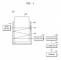
- FIG. 1 is a conceptual diagram schematically showing a water examination device 100 according to an embodiment of the present disclosure
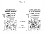
- FIG. 2 is a diagram for describing principles of a chaotic wave sensor according to an embodiment of the present disclosure
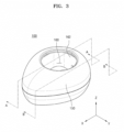
- FIG. 3 is a perspective view of a water examination device actually implemented from the conceptual diagram of FIG. 1
- FIG. 4 is a cross-sectional view taken along line A-A of FIG. 3 and shows a state in which a cup is accommodated in a cup accommodation unit
- FIG. 5 is a cross-sectional view taken along line B-B of FIG. 3
- FIG. 6 is a plan view of the water examination device of FIG. 3
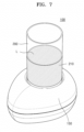
- FIG. 7 is a perspective view showing a cup mounted in the cup accommodation unit of FIG. 3 .
- the water examination device 100 may include a wave source 110, a detector 120, and a controller 130.
- the water examination device 100 of FIG. 1 may further include an alarm unit 140 and a cup accommodation unit 160 (see FIG. 4 ).
- a cup 200 containing a fluid L that is an object to be examined may be accommodated in the cup accommodation unit 160.
- the cup accommodation unit 160 may include a multi-scattering amplification region 165 for amplifying the number of times that the wave irradiated from the wave source 110 is multiple scattered in the fluid L.
- the fluid L may be a liquid or a gas.
- the fluid L may be a material in which microorganisms may proliferate, for example, water that does not contain a scattering material therein.
- the present disclosure is not limited thereto, and in another embodiment, the fluid L may be a material such as milk having a scattering material therein.
- the fluid L does not include the scattering material will be described first, and the fluid L including the scattering material will be described later.
- the wave source 110 may irradiate a wave toward the fluid L in the cup 200 accommodated in the cup accommodation unit 160.
- the wave source 110 may include all kinds of source devices capable of generating waves, for example, may be a laser capable of irradiating light of a certain wavelength band.
- the detector 120 may detect whether there are microorganisms M, e.g., impurities, in the fluid L, by using the wave.
- the detector 120 may include a chaotic wave sensor.
- the impurities may include insoluble suspended matters.
- the detector 120 may also execute a function of detecting impurities included in the fluid L, as well as the microorganisms M. However, for convenience of description, the case of detecting the microorganism (M) in the fluid (L) will be described below.
- wave in light or wave (hereinafter, referred to as wave for convenience' sake) irradiated from a wave source 110, some of the waves scattered through complicated paths due to the multiple scattering passes through a test target surface. Waves passing through multiple points in the test target surface generate constructive interference or destructive interference, and the constructive/destructive interference of the waves generates grain patterns (speckles).
- the waves scattered in the complicated paths are referred to as "chaotic wave", and the chaotic wave may be detected through laser speckles.
- FIG. 2 shows a state in which a laser is irradiated to a stabilized medium.
- interference light e.g., laser
- the stabilized medium in which internal component material does not move, a stabilized speckle pattern without a variation may be observed.
- the speckle pattern varies.
- an optical path may be minutely changed over time due to minute biological activities of living things (e.g., intracellular movement, movement of microorganisms, movement of mites, etc.). Because the speckle pattern is generated due to interference of the waves, a minute change in the optical path may cause a variation in the speckle pattern. Accordingly, when a temporal variation in the speckle pattern is measured, movements of living things may be rapidly measured. As described above, when the variation in the speckle pattern according to time is measured, existence of the living things and concentration of the living things may be identified, and further, kinds of the living things may be identified.
- a structure for measuring the variation in the speckle pattern is defined as a chaotic wave sensor.
- the water examination device 100 may generate a stabilized laser speckle pattern by multi-scattering waves through a multi-scattering amplification region 165 that will be described later.
- the path of the wave may be minutely changed by the movement of the microorganisms.
- the minute change in the wave path may cause a change in the speckle pattern, and accordingly, by measuring the temporal change of the speckle pattern, the presence or absence of the microorganisms M in the fluid L may be rapidly detected.
- the water examination device 100 may include the wave source 110, the detector 120, and the controller 130.
- the wave source 110 may irradiate a wave toward the fluid L in the cup 200 accommodated in the cup accommodation unit 160.
- the wave source 110 may include all kinds of source devices capable of generating waves, for example, may be a laser capable of irradiating light of a certain wavelength band.
- the present disclosure is not limited to the kind of wave source, for convenience of description, a case in which the wave source is a laser will be described below.
- the laser having excellent coherence may be used as the wave source 110 in order to form speckles in the fluid L.
- a spectral bandwidth of the wave source when a spectral bandwidth of the wave source is shorter, a measuring accuracy may increase, wherein the spectral bandwidth determines the coherence of the laser wave source. That is, when a coherence length increases, the measuring accuracy also increases.
- a wave source irradiating the laser having a spectral bandwidth that is less than a reference bandwidth set in advance may be used as the wave source 110, and when the spectral bandwidth is reduced shorter than the reference bandwidth, the measuring accuracy may increase.
- the spectral bandwidth of the wave source may be set to satisfy following condition of Equation 1 below. Spectralbandwidth ⁇ 5 nm
- the spectral bandwidth of the wave source 110 may be maintained to be less than 5 nm.
- the detector 120 may detect the laser speckle generated by the irradiated wave multi-scattered in the fluid L at every preset time point.
- the time point may denote one instant during continuous flow of time, and time points may be set in advance with constant time intervals therebetween, but are not limited thereto, that is, may be set in advance with an arbitrary time interval.
- the detector 120 may include a sensing unit corresponding to the kind of the wave source 110, for example, a CCD camera that is an imaging device in a case where a light source of a visible ray wavelength band is used.
- the detector 120 may detect the laser speckle at a first time point at least, and may detect the laser speckle at a second time point, and then, may provide the controller 130 with the detected laser speckles.
- the first time point and the second time point are just examples selected for convenience of description, and the detector 120 may detect laser speckles at a plurality of time points more than the first and second time points.
- the incident wave may generate laser speckle due to the multiple scattering.
- the laser speckle is generated by the light interference effect, and thus, when there is no microorganism in the fluid L, a constant interference pattern may be shown over time due to the multi-scattering amplification region.
- the laser speckle may vary over time due to the movement of the microorganisms M.
- the detector 120 detects the laser speckle varying over the time at every time point set in advance, to provide the laser speckle to the controller 130.
- the detector 120 may detect the laser speckle at a sufficient speed to sense the movement of the microorganisms M, for example, 25 frames to 30 frames per second.
- the image sensor may be arranged so that a size d of one pixel in the image sensor is equal to or less than a grain size of the speckle pattern.
- the image sensor may be arranged in an optical system included in the detector 120 to satisfy the condition of Equation 2 below. d ⁇ speckle grain size
- the size d of one pixel in the image sensor has to be equal to or less than the grain size of the speckle pattern, but when the size of the pixel is too small, an undersampling may occur and it may be difficult to utilize the pixel resolution. Accordingly, in order to achieve an effective signal to noise ratio (SNR), the image sensor may be arranged such that maximum five pixels correspond to the speckle grain size.
- SNR signal to noise ratio
- the controller 130 may obtain a temporal correlation of the detected laser speckle, by using the detected laser speckle.
- the controller 130 may estimate, in real-time, the existence of the microorganisms in the fluid L, based on the obtained temporal correlation.
- real-time denotes estimating whether the microorganisms M exist within three seconds, for example, the existence of the microorganisms M may be estimated within one second.
- the controller 130 may estimate whether the microorganisms M exist by using a difference between first image information of the laser speckle detected at a first time point and second image information of the laser speckle detected at a second time point that is different from the first time point.
- the first image information and the second image information may include at least one of laser speckle pattern information and wave intensity information.
- the difference between the first image information at the first time point and the second image information at the second time point is not only used, but image information of a plurality of laser speckles at a plurality of time points may be also used.
- the controller 130 may calculate a temporal correlation coefficient between the images by using image information of the laser speckles generated at the plurality of time points set in advance, and may estimate existence of the microorganisms M in the fluid L based on the temporal correlation coefficient.
- the temporal correlation between the detected laser speckle images may be calculated by using Equation 3 below.
- C denotes the temporal correlation coefficient
- I denotes a normalized light intensity
- (x,y) denotes a pixel coordinate of the camera
- t denotes a measured time
- T denotes a total measured time
- ⁇ denotes a time lag
- the temporal correlation coefficient may be calculated, and in an embodiment, the existence of the microorganisms may be estimated by analyzing whether the temporal correlation coefficient is below a reference value set in advance. In more detail, when the temporal correlation coefficient is below the reference value beyond an error range set in advance, it may be estimated that the microorganisms exist.
- the detector 120 may estimate a concentration of impurities in the fluid L accommodated in the cup 200.
- the detector 120 may perform a function of measuring a turbidity of the fluid L by estimating the concentration of the impurities in the fluid L. It is difficult to measure an impurity concentration of 105 cfu/ml or less by using a general turbidity measurement device.
- the detector 120 according to the embodiment of the present disclosure may measure the impurity concentration of 106 cfu/ml or less by using a method of determining a concentration of the impurities as described below.
- impurities are not limited to microorganisms.
- a method of determining the concentration of the impurities by using the laser speckle in the controller 130 will be described in detail below, based on the case in which the impurities include the microorganisms.
- the controller 130 may calculate a standard deviation of light intensity of the laser speckle, on a laser speckle image measured at every reference time. As the microorganisms included in the fluid L continuously move, constructive interference and destructive interference may vary according to the movements. Here, when the constructive interference and the destructive interference change, the light intensity may largely change. Then, the controller 130 may calculate the standard deviation representing the variation degree of the light intensity, to detect the microorganisms in the cup 200, and may measure the distribution of the microorganisms.
- the controller 130 may combine the laser speckle image at every time point determined in advance, and may calculate the standard deviation of the light intensity of the laser speckle over time in the combined image.
- the standard deviation of the light intensity of the laser speckle over time may be calculated by using Equation 4 below.
- Equation 4 S denotes the standard deviation, (x,y) denotes a pixel coordinate of the camera, T denotes a total measurement time, t denotes a measurement time, It denotes a light intensity measured at the time t, and I denotes an average light intensity according to time.
- the constructive and destructive interferences may vary depending on the movements of the microorganisms, and the standard deviation value calculated according to the Equation 4 increases.
- the concentration of the microorganisms may be measured based on the standard deviation value.
- the present disclosure is not limited to the method of measuring the concentration of microorganisms by using Equation 4 above, and the concentration of microorganisms may be measured by any method using a difference in the detected laser speckle.
- controller 130 may measure distribution, that is, concentration of the microorganisms included in the fluid, based on a linear relationship between a magnitude of the standard deviation value of the laser speckle light intensity and the concentration of the microorganisms.
- the multi-scattering amplification region 165 may amplify the number of multiple scattering in the fluid L by reflecting at least some of the waves emitted from the fluid L toward the fluid L again.
- the multi-scattering amplification region 165 may include a multiple scattering material.
- the multiple scattering material may include a particle having a diameter equal to or less than a micrometer and having a large refractive index, for example, titanium oxide (TiO 2 ) nano-particles.
- the multi-scattering amplification region 165 may be formed by coating the multiple scattering material on surfaces of a bottom portion 161 (see FIG. 4 ) and a wall portion 162 (see FIG. 4 ) of the cup accommodation unit 160.
- the multi-scattering amplification region 165 is formed by including the multiple scattering material in the bottom portion 161 (see FIG. 4 ) and the wall portion 162 (see FIG. 4 ).
- the multi-scattering amplification region 165 may be provided as a reflection region 167 that reflects all of the waves emitted from the fluid L to the fluid L.
- the reflection region 167 may reduce the emission of waves to outside of the water examination device 100 from the fluid L, so as to amplify a microorganism detecting rate of the detector 120.
- the reflection region 167 may be disposed to face an incident region where the wave from the wave source 110 is incident.
- the reflection region 167 reflects all of the waves irradiated from the wave source 110 into the fluid L, and thus, an amount of waves that may be multiple scattered in the fluid L may be increased.
- the microorganism sensing rate of the detector 120 may be amplified.
- an entire area of the multi-scattering amplification region 165 rather than a moving path of the waves emitted toward the detector 120, may include the reflection region.
- the water examination device 100 may further include the alarm unit 140.
- the water examination device 100 may be connected to a terminal 20 outside or a server (not shown) via a network.
- the alarm unit 140 may notify a user of the signal.
- the alarm unit 140 may notify that the microorganisms exist in the fluid by using at least one of sound and light.
- the alarm unit 140 may include a lighting unit such as an LED for generating a warning signal via light and a speaker (not shown) for generating a warning signal via sound, and the light and sound may be generated at the same time.
- the water examination device 100 may further include a communication unit (not shown) that may communicate with the terminal 20 of a user.
- the alarm unit 140 may provide the terminal 20 with information including the microorganism sensing signal through a wireless or wired communication unit (not shown). Also, although not shown in the drawing, the alarm unit 140 may provide the above information to a server (not shown).
- the water examination device 100 registers the information on the server (not shown) and provides an interface through which other users may search for the data registered on the server (not shown).
- the water examination device 100 may establish a situation in which microorganisms are generated, etc. as a database through the above processes.
- the terminal 20 may include a personal computer or a portable terminal on which a Web service may be used under a wired/wireless communication environment.
- the water examination device 100 may include the wave source 110, the detector 120, a main body 150, and the cup accommodation unit 160.
- the water examination device 100 may further include the controller 130 (see FIG. 1 ) and the alarm unit 140 (see FIG. 1 ) described with reference to FIG. 1 .
- the controller 130 see FIG. 1
- the alarm unit 140 see FIG. 1
- the main body 150 forms the outer appearance of the water examination device 100, and the wave source 110, the detector 120, and the cup accommodation unit 160 may be provided in the main body 150.
- the main body 150 forms an eccentric streamlined shape (or an egg-like shape when viewed from above) as a whole, and the cup accommodation unit 160, in which the cup 200 may be fitted therein from the upper portion thereof, is formed.
- the present disclosure is not limited thereto, a size, a shape, and a material of the main body 150 or a location in the main body 150, where the cup accommodation unit 160 is formed, may be variously changed.
- the cup accommodation unit 160 may be formed such that the cup 200 may be fitted therein from the upper portion of the main body 150 to the inside (e.g., the center side).
- the cup accommodation unit 160 may include the bottom portion 161 and the wall portion 162. In other words, it may be expressed that the cup accommodation unit 160 in which the cup 200 may be accommodated and mounted is formed by the bottom portion 161 and the wall portion 162.
- the bottom portion 161 forms a bottom surface of the cup accommodation unit 160 and has a substantially flat shape.
- the multi-scattering amplification region 165 described above may be formed in at least a part of the bottom portion 161.
- three or more support portions 161a protrude from the bottom portion 161 so as to stably support the cup 200 accommodated in the cup accommodation unit 160.
- the cup 200 containing the fluid has various shapes, some of which may not have flat bottom surfaces. In this case, when the cup 200 is seated in the cup accommodation unit 160, the cup 200 may not stop and be minutely shaken, and there may be an error in the measurement value.
- three or more support portions 161a protrude from the bottom portion 161 so as to stably support the cup 200 accommodated in the cup accommodation unit 160.
- the bottom portion 161 and the bottom surface of the cup 200 come into contact with each other at three (or more) points, rather than a surface contact, and through the above three-point contact, the shaking of the cup 200 that may occur when the bottom surface of the cup 200 is not flat may be reduced, thereby improving a precision during repeated measurements.
- the wall portion 162 is nearly perpendicular to the bottom portion 161, and has an annular shape so that the cup 200 may be accommodated therein.
- the multi-scattering amplification region 165 and/or the reflection region 167 described above may be formed in at least a part of the wall portion 162.
- an angle ⁇ between the wall portion 162 and the bottom portion 161 is not exactly a right angle, but is slightly inclined (i.e., obliquely).
- the water examination device 100 has a structure, in which a portion where the cup accommodation unit 160 is formed, is opened in order to accommodate the cup 200.
- a portion where the cup accommodation unit 160 is formed is opened in order to accommodate the cup 200.
- the angle ⁇ between the wall portion 162 and the bottom portion 161 is not exactly a right angle, but is slightly inclined. That is, the wall portion 162 is formed such that the angle ⁇ between the wall portion 162 and the bottom portion 161 is about 85° to 88°, and the laser reflected by the wall portion 162 may proceed opposite to the opened surface to reduce the loss in the light intensity. Thus, the light scattering effect may be improved.
- the wall portion 162 is formed to have an entrance that gradually narrows upward (that is, in a +Z axis direction), or it may be expressed that a diameter thereof is gradually reduced upward. According to the present disclosure as described above, the loss in the light emitted from the wave source 110 to outside is reduced, and the light scattering effect may be improved.
- the cup 200 may include an opaque portion 210.
- the laser is exposed to outside, and then, a glaring effect may occur to the user.
- the opaque portion 210 is formed in at least a part of the cup 200, in particular, to a certain height in the lower portion of the side surface of the cup 200, and thus, the minimum amount of fluid that is necessary for inspecting the water quality of the fluid is indicated to the user, and at the same time, the user may not directly see the laser.
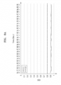
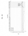
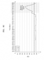
- FIGS. 8A to 8C are graphs showing temporal correlation coefficients according to a bacterial concentration in a fluid in a water examination device according to an embodiment of the present disclosure.
- FIGS. 8A to 8C show a variation in the temporal correlation coefficient according to a concentration of microorganisms, when the microorganisms are artificially introduced into the fluid contained in the cup 200.
- an x-axis denotes time (t) and a y-axis denotes a temporal correlation coefficient (C(t)).
- a dashed line L2 represents a reference value of the temporal correlation coefficient of the laser speckle set in advance in the detector 120.
- a solid line L1 represents measurement data of the temporal correlation coefficient of the laser speckle obtained by the detector 120 over time.
- the solid line L1 denotes the temporal correlation coefficient of the laser speckle obtained by the detector 120 when the microorganisms are not introduced in the fluid.
- the temporal correlation coefficient is nearly consistent over time and does not exceed the reference value (L1) set in advance.
- the solid line L1 of FIG. 8B indicates the temporal correlation coefficient of the laser speckle obtained through the detector 120 when 4 ml of microorganisms with a concentration of 10 ⁇ 0 cfu/ml is introduced into the fluid.
- the solid line L1 of FIG. 8C indicates the temporal correlation coefficient of the laser speckle obtained through the detector 120 when 4 ml of microorganisms with a concentration of 10 ⁇ 1 cfu/ml is introduced into the fluid.
- FIGS. 8B and 8C when the microorganisms exist in the fluid, the laser speckle generated due to the scattering in the fluid changes over time, and thus, the temporal correlation coefficient is changed at a time point when the microorganisms are sensed.
- Shaded areas (bacteria detecting signal) in FIGS. 8B and 8C indicate the change in the temporal correlation coefficient at the time point when the microorganisms are detected, and it may be identified that a peak value of the temporal correlation coefficient increases as the concentration of the microorganisms increases. Meanwhile, in the shaded areas of FIGS.
- the detector 120 may determine that the microorganisms exist when the temporal correlation coefficient (L1) of the laser speckle exceeds the dashed line L2 that is the reference value set in advance.
- a time taken for the detector 120 to detect the microorganisms may include a period from the time point when the temporal correlation coefficient rapidly changes to a time point when the temporal correlation coefficient meets the dashed line L2, e.g., the reference value, and may be about 0.2 sec. or less based on FIGS. 8B and 8C .
- the water examination device may sense the microorganisms, e.g., impurities, in the fluid within a very short time period of 0.2 sec. or less, that is, in real-time. Also, the water examination device according to the embodiments of the present disclosure may estimate the concentration of the microorganisms by using a change rate or a peak value of the temporal correlation coefficient. In addition, it may be identified that the water examination device may detect microorganisms even when the concentration of the microorganisms is low (10 ⁇ 0 cfu/ml).
- the water examination device may estimate the existence of the microorganisms in the fluid or the concentration of the microorganisms rapidly at low costs, by using the variation in the temporal correlation of the laser speckle.
- the existence or the concentration of the microorganisms in the fluid is detected by using a spatial correlation, instead of the temporal correlation.
- the method will be described below in more detail.
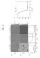
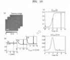
- FIGS. 9 and 10 are diagrams for describing principles of detecting the microorganisms in a water examination device according to another embodiment of the present disclosure.
- the controller 130 may receive optical images measured in a time-serial manner from the detector 120, and may determine the concentration information of microorganisms in a sample from the optical images.
- the controller 130 may obtain a spatial correlation of an interference pattern.
- the spatial correlation given by the equation below may represent, in a number within a certain range, how similar is between a brightness of a certain pixel and a brightness of another pixel away from the certain pixel by a distance r on an image measured at a time point t (see (b) of FIG. 10 ).
- the range may be between -1 and 1. That is, the spatial correlation indicates a degree of correlation between a certain pixel and another pixel, that is, 1 denotes a positive correlation, -1 denotes a negative correlation, and 0 denotes no correlation.
- the spatial correlation of a sample image denotes the positive correlation close to 1, but after the interference pattern is formed, the value of the correlation may be reduced toward 0.
- the spatial correlation may be expressed by Equation 5 below.
- C r t 1 C 0 t ⁇ I r ′ + r , t I r ′ , t dr ′
- C 0 (t) was used to adjust the range of Equation 5 to -1 to 1.
- the spatial correlation has a value of 1, and when the brightness is not identical, the spatial correlation has a value less than 1.
- the present disclosure may express the above spatial correlation only as a function of time.
- the controller 130 may obtain an average of the spatial correlation for a certain pixel and a pixel having the same size and away from by the distance r as in Equation 6 below (refer to (b) of FIG. 10 ).
- C ⁇ t 1 2 ⁇ ⁇ 0 2 ⁇ C r t d ⁇
- the controller 130 may express the distance set in advance as a function of time by substituting the distance into Equation 6 above, and may identify a degree of forming the interference pattern as a value ranging from 0 to 1 (see (d) of FIG. 10 ).
- the controller 130 may distinguish foreign substances from microorganisms in the sample through a change in the pattern of the sample image over time. In the case of foreign substances, there is no change in the image over time, but images such as shapes, sizes, etc. of the microorganisms are changed over time, and thus, the water examination device 100 may distinguish the foreign substances from the microorganisms.
- the controller 130 may determine the concentration information of the microorganisms by using the spatial correlation as follows.
- the spatial correlation may be obtained by generating two identical images overlapping each other by using one image, shifting one of the two images by a preset distance in one direction, and analyzing how similar the two pixels are between the shifted image and the image that is not shifted.
- the spatial correlation is a measure indicating how uniform an image is. When an interference pattern is formed due to a colony, similarity between two adjacent pixels decreases due to the small interference pattern, and a value of the spatial correlation also decreases.
- the spatial correlation coefficient changes according to the shifted distance r (see (b) of FIG. 9 ), that is, the value of the spatial correlation coefficient decreases as the shifted distance r increases within a certain distance range and is nearly consistent when exceeding the certain distance range.
- the controller 130 may obtain the spatial correlation by shifting the image by a certain distance set in advance or more.
- the certain distance r set in advance depends on the speckle size, and the controller 130 may obtain the spatial correlation by shifting the image by a pixel that is greater than the speckle size when expressed in units of pixels.
- the certain distance set in advance may be at least 3 pixels or more.
- the controller 130 may obtain a temporal correlation of the interference pattern of the measured sample image, as well as the spatial correlation as described above, and may detect the microorganisms based on the obtained temporal correlation.
- the controller 130 may calculate a temporal correlation coefficient between images by using image information of the interference pattern measured in a time-serial manner, and may detect a microorganism colony in the sample based on the temporal correlation coefficient.
- the controller 130 may detect the microorganism through analysis about when the calculated temporal correlation coefficient falls below a reference value set in advance.
- the water examination device 100 may further include a multiple scattering amplification member for amplifying the number of times that the light incident into the cup 200 is multiple scattered in the sample.
- a multiple scattering amplification member (not shown) is provided on a movement path of light between the wave source 110 and the cup 200 or between the cup 200 and the detector 120, and may amplify the number of times that the light is multiple scattered.
- the multiple scattering amplification member (not shown) may be installed on or detached from the water examination device 100, and may be used as necessary.
- the water examination device according to the embodiments of the present disclosure may detect the microorganisms in the fluid in the cup 200 within a short period of time.
- a water examination device there is provided a water examination device. Also, embodiments of the present disclosure may be applied to a device for measuring foreign substances in a fluid, etc.
Applications Claiming Priority (2)
| Application Number | Priority Date | Filing Date | Title |
|---|---|---|---|
| KR1020200120698A KR102407130B1 (ko) | 2020-09-18 | 2020-09-18 | 수질 검사기 |
| PCT/KR2020/012995 WO2022059829A1 (fr) | 2020-09-18 | 2020-09-24 | Dispositif d'inspection de la qualité de l'eau |
Publications (2)
| Publication Number | Publication Date |
|---|---|
| EP4215899A1 true EP4215899A1 (fr) | 2023-07-26 |
| EP4215899A4 EP4215899A4 (fr) | 2024-01-24 |
Family
ID=80776866
Family Applications (1)
| Application Number | Title | Priority Date | Filing Date |
|---|---|---|---|
| EP20926373.0A Pending EP4215899A4 (fr) | 2020-09-18 | 2020-09-24 | Dispositif d'inspection de la qualité de l'eau |
Country Status (5)
| Country | Link |
|---|---|
| US (1) | US20220317104A1 (fr) |
| EP (1) | EP4215899A4 (fr) |
| KR (1) | KR102407130B1 (fr) |
| CN (1) | CN114556089A (fr) |
| WO (1) | WO2022059829A1 (fr) |
Family Cites Families (7)
| Publication number | Priority date | Publication date | Assignee | Title |
|---|---|---|---|---|
| CN108351362B (zh) * | 2015-05-28 | 2021-12-31 | Bd科斯特公司 | 获取和制备用于鉴定和抗生素敏感性试验的微生物样品的自动化方法和系统 |
| CN108474740B (zh) * | 2015-11-17 | 2021-03-02 | 韩国科学技术院 | 利用混沌波传感器的样品特性探测装置 |
| KR101971272B1 (ko) * | 2016-06-02 | 2019-08-27 | 주식회사 더웨이브톡 | 패턴 구조물 검사 장치 및 검사 방법 |
| KR101920852B1 (ko) * | 2016-11-14 | 2018-11-21 | 주식회사 더웨이브톡 | 미생물 존재 검출용 포장용기, 이를 포함하는 미생물 존재 검출용 시스템 및 이를 이용한 포장용기 내의 미생물 존재 검출방법 |
| KR101939779B1 (ko) * | 2017-09-12 | 2019-01-18 | 주식회사 더웨이브톡 | 혼돈파 센서를 이용한 유체 내 미생물 감지 시스템 |
| JP2019058126A (ja) * | 2017-09-27 | 2019-04-18 | 株式会社マクシスエンジニアリング | 水質管理方法 |
| US11156541B2 (en) * | 2018-05-18 | 2021-10-26 | The Wave Talk, Inc. | Optical detecting system |
-
2020
- 2020-09-18 KR KR1020200120698A patent/KR102407130B1/ko active IP Right Grant
- 2020-09-24 US US17/600,521 patent/US20220317104A1/en active Pending
- 2020-09-24 CN CN202080026281.1A patent/CN114556089A/zh active Pending
- 2020-09-24 WO PCT/KR2020/012995 patent/WO2022059829A1/fr unknown
- 2020-09-24 EP EP20926373.0A patent/EP4215899A4/fr active Pending
Also Published As
| Publication number | Publication date |
|---|---|
| KR102407130B1 (ko) | 2022-06-10 |
| KR20220037795A (ko) | 2022-03-25 |
| EP4215899A4 (fr) | 2024-01-24 |
| CN114556089A (zh) | 2022-05-27 |
| US20220317104A1 (en) | 2022-10-06 |
| WO2022059829A1 (fr) | 2022-03-24 |
Similar Documents
| Publication | Publication Date | Title |
|---|---|---|
| US10724949B2 (en) | Cuvette for detecting bacteria and determining their susceptibility to antibiotics | |
| US7292338B2 (en) | Particle detection apparatus and particle detection method used therefor | |
| AU2015292225B2 (en) | Method and device for bone scan in meat | |
| EP3171160B1 (fr) | Appareil et procédé pour détecter des microbes ou des bactéries | |
| US5748311A (en) | Apparatus and method of particle geometry measurement by speckle pattern analysis | |
| US10830687B2 (en) | Measuring arrangement for in-line holography microscopy | |
| US20130135608A1 (en) | Apparatus and method for improved processing of food products | |
| US20150369733A1 (en) | Dynamic light scattering measurement device and dynamic light scattering measurement method | |
| US20080018893A1 (en) | Instrument using near-field intensity correlation measurements for characterizing scattering of light by suspensions | |
| EP4215899A1 (fr) | Dispositif d'inspection de la qualité de l'eau | |
| KR102566721B1 (ko) | 수질 검사기 | |
| KR102543670B1 (ko) | 탁도계 | |
| KR102496066B1 (ko) | 수질 검사기 | |
| RU2413930C1 (ru) | Способ определения оптических характеристик однородного рассеивающего вещества | |
| EP3496031B1 (fr) | Détection d'objets microscopiques dans des fluides | |
| US20230288307A1 (en) | Interferometric scattering correlation (iscorr) microscopy | |
| RU2377541C1 (ru) | Способ измерения оптических характеристик жидкости или газа | |
| KR20230120485A (ko) | 탁도 모니터링 장치 |
Legal Events
| Date | Code | Title | Description |
|---|---|---|---|
| STAA | Information on the status of an ep patent application or granted ep patent |
Free format text: STATUS: UNKNOWN |
|
| STAA | Information on the status of an ep patent application or granted ep patent |
Free format text: STATUS: THE INTERNATIONAL PUBLICATION HAS BEEN MADE |
|
| PUAI | Public reference made under article 153(3) epc to a published international application that has entered the european phase |
Free format text: ORIGINAL CODE: 0009012 |
|
| STAA | Information on the status of an ep patent application or granted ep patent |
Free format text: STATUS: REQUEST FOR EXAMINATION WAS MADE |
|
| 17P | Request for examination filed |
Effective date: 20210930 |
|
| AK | Designated contracting states |
Kind code of ref document: A1 Designated state(s): AL AT BE BG CH CY CZ DE DK EE ES FI FR GB GR HR HU IE IS IT LI LT LU LV MC MK MT NL NO PL PT RO RS SE SI SK SM TR |
|
| REG | Reference to a national code |
Ref country code: DE Ref legal event code: R079 Free format text: PREVIOUS MAIN CLASS: G01N0015020000 Ipc: G01N0033180000 |
|
| DAV | Request for validation of the european patent (deleted) | ||
| DAX | Request for extension of the european patent (deleted) | ||
| A4 | Supplementary search report drawn up and despatched |
Effective date: 20240104 |
|
| RIC1 | Information provided on ipc code assigned before grant |
Ipc: G01N 21/94 20060101ALI20231221BHEP Ipc: G01N 21/51 20060101ALI20231221BHEP Ipc: G01N 21/47 20060101ALI20231221BHEP Ipc: G01N 15/14 20060101ALI20231221BHEP Ipc: G01N 15/02 20060101ALI20231221BHEP Ipc: G01N 33/18 20060101AFI20231221BHEP |