EP4215889A1 - Common signal conditioning circuit for temperature sensor - Google Patents
Common signal conditioning circuit for temperature sensor Download PDFInfo
- Publication number
- EP4215889A1 EP4215889A1 EP23151309.4A EP23151309A EP4215889A1 EP 4215889 A1 EP4215889 A1 EP 4215889A1 EP 23151309 A EP23151309 A EP 23151309A EP 4215889 A1 EP4215889 A1 EP 4215889A1
- Authority
- EP
- European Patent Office
- Prior art keywords
- sensor
- temperature
- resistance
- current
- voltage
- Prior art date
- Legal status (The legal status is an assumption and is not a legal conclusion. Google has not performed a legal analysis and makes no representation as to the accuracy of the status listed.)
- Granted
Links
Images





Classifications
-
- G—PHYSICS
- G01—MEASURING; TESTING
- G01K—MEASURING TEMPERATURE; MEASURING QUANTITY OF HEAT; THERMALLY-SENSITIVE ELEMENTS NOT OTHERWISE PROVIDED FOR
- G01K7/00—Measuring temperature based on the use of electric or magnetic elements directly sensitive to heat ; Power supply therefor, e.g. using thermoelectric elements
- G01K7/16—Measuring temperature based on the use of electric or magnetic elements directly sensitive to heat ; Power supply therefor, e.g. using thermoelectric elements using resistive elements
- G01K7/18—Measuring temperature based on the use of electric or magnetic elements directly sensitive to heat ; Power supply therefor, e.g. using thermoelectric elements using resistive elements the element being a linear resistance, e.g. platinum resistance thermometer
- G01K7/20—Measuring temperature based on the use of electric or magnetic elements directly sensitive to heat ; Power supply therefor, e.g. using thermoelectric elements using resistive elements the element being a linear resistance, e.g. platinum resistance thermometer in a specially-adapted circuit, e.g. bridge circuit
-
- G—PHYSICS
- G01—MEASURING; TESTING
- G01K—MEASURING TEMPERATURE; MEASURING QUANTITY OF HEAT; THERMALLY-SENSITIVE ELEMENTS NOT OTHERWISE PROVIDED FOR
- G01K7/00—Measuring temperature based on the use of electric or magnetic elements directly sensitive to heat ; Power supply therefor, e.g. using thermoelectric elements
- G01K7/16—Measuring temperature based on the use of electric or magnetic elements directly sensitive to heat ; Power supply therefor, e.g. using thermoelectric elements using resistive elements
- G01K7/22—Measuring temperature based on the use of electric or magnetic elements directly sensitive to heat ; Power supply therefor, e.g. using thermoelectric elements using resistive elements the element being a non-linear resistance, e.g. thermistor
- G01K7/24—Measuring temperature based on the use of electric or magnetic elements directly sensitive to heat ; Power supply therefor, e.g. using thermoelectric elements using resistive elements the element being a non-linear resistance, e.g. thermistor in a specially-adapted circuit, e.g. bridge circuit
Definitions
- Embodiments of the present disclosure relate to motor control drive systems for a vehicle, and more particularly, to temperature measurement circuits employed in motor control drive system of an aircraft.
- Power switch heat sink temperature is a critical parameter to be monitored in motor control drives.
- Resistance temperature detectors (RTDs) and thermistors are the most used temperature sensors due to their low cost and reliability.
- the two types of thermistors that are typically used are Positive Temperature Coefficient (PTC) thermistors and Negative Temperature Coefficient (NTC) thermistors. While RTDs and thermistors both have resistances that vary as a function of temperature, the resistance of a PTC increases linearly in response to temperature changes compared to the resistance of an NTC which decreases linearly in response to temperature changes.
- ratiometric temperature measurement system includes a sensing circuit to measure a temperature and a controller to determine a resistance (R T_SENSOR ) corresponding to the sensing circuit.
- the sensing circuit includes a temperature sensing circuit and a current sensor.
- the sensing circuit utilize an electrical current (Io) to output a first voltage indicative of a first voltage differential (V T_SENSOR ) across the temperature sensing circuit and to output a second voltage indicative of a second voltage differential (V C_SENSOR ) across the current sensor.
- the controller is configured to determine a resistance (R T_SENSOR ) corresponding to the temperature sensing circuit based at least in part on the first and second voltage differentials (V T_SENSOR and V C_SENSOR ).
- the controller determines a temperature value (T OUT ) indicative of the measured temperature based on the resistance (R T__SENSOR ).
- the controller determines a current level (I exc ) of the current (Io) based on the second voltage differential (V C_SENSOR ) indicated by the current sensor and a resistance (R C_SENSE ) of the current sensor.
- the resistance (R T_SENSOR ) of the current sensor is determined as a ratio of the first voltage differential (V T_SENSOR ) to the current level (I exc ).
- the controller comprises memory and a processor.
- the memory is configured to store a look-up table (LUT) populated with a plurality of predetermined resistance values that are mapped to corresponding predetermined temperature values.
- the processor is in signal communication with the memory.
- the processor is configured to compare the resistance (R T_SENSOR ) of the current sensor to the predetermined resistance values, select a predetermined temperature value corresponding to the predetermined resistance value that matches the resistance (R T_SENSOR ), and output the selected predetermined temperature value as the temperature value (T OUT ).
- the sensing circuit comprises a temperature sensor configured to effect the first voltage differential (V T_SENSOR ) in response to the current (Io); and an adjustable linearization resistance element (R p ) configured to selectively add or remove a resistance realized by the temperature sensor.
- the temperature sensor includes a first terminal connected to the current sensor to receive the current and a second terminal connected to a ground potential.
- a current excitation circuit including a constant current source is configured to generate the current.
- the current sensor is in signal communication with the current excitation circuit and is configured to effect the second voltage differential (V C_SENSOR ) thereacross in response to the current.
- the current sensor includes a current sense resistor having a fixed resistance that defines the resistance (R C_SENSE ) of the current sensor.
- a voltage drop across the sense resistor defines the second voltage differential (V C_SENSOR ).
- the system includes a multiplexer (MUX) and an amplifier circuit.
- Th MUX is configured to selectively output the first filtered voltage differential (V T_SENSOR ) or the second filtered voltage differential (V C_SENSOR ) in response to a control signal generated by the controller.
- the amplifier circuit is in signal communication with the MUX.
- the amplifier circuit is configured to amplify the first voltage differential (V T_SENSOR ) and to amplify the second voltage differential (V C_SENSOR ).
- a filter circuit in signal communication with the sensing circuit, the filter circuit configured to filter the first voltage differential (V T_SENSOR ) and the second voltage differential (V C_SENSOR ) and output the filtered first and second voltage differentials to the amplifier circuit.
- an analog-to-digital converter including an input connected to the amplifier circuit and an output connected to the controller, the ADC configured to generate a first digital signal indicative (of the first voltage differential (V T_SENSOR ) and a second digital signal indicative of the second voltage differential (V C_SENSOR ).
- the temperature sensor is a RTD
- the adjustable linearization resistance element is connected in parallel with the RTD so as to establish an open circuit in parallel with the RTD.
- the temperature sensor is an NTC and the adjustable linearization resistance element is connected in parallel with the NTC to establish a targeted resistance that shunts the NTC and linearizes the first voltage differential.
- a method of measuring a temperature comprises delivering an electrical current (Io) to a sensing circuit, outputting a first voltage from a temperature sensing circuit included in the sensing circuit in response to the electrical current, and outputting a second voltage from a current sensor included in the sensing circuit.
- the first voltage is indicative of a first voltage differential (V T_SENSOR ) and the second voltage is indicative of a second voltage differential (V C_SENSOR ).
- the method further comprises determinizing a resistance (R T_SENSOR ) corresponding to the temperature sensing circuit based at least in part on the first and second voltage differentials (V T_SENSOR and V C_SENSOR ).
- the method further comprises determining a temperature value (T OUT ) indicative of the temperature based on the resistance (R T_SENSOR ).
- the method further comprises determining, using the controller, a current level (I exc ) of the current (I o ) based on the second voltage differential (V C_SENSOR ) indicated by the current sensor and a resistance (R C_SENSE ) of the current sensor.
- the method further comprises determining the resistance (R T_SENSOR ) of the current sensor as a ratio of the first voltage differential (V T_SENSOR ) to the current level (I exc ).
- the method further comprises selectively adding or removing a resistance realized by the temperature sensor using an adjustable linearization resistance element (R p ).
- the method further comprises populating a look-up table (LUT) with a plurality of predetermined resistance values that are mapped to corresponding predetermined temperature values; comparing, by the controller, the resistance (R T_SENSOR ) of the current sensor to the predetermined resistance values; selecting, by the controller, a predetermined temperature value corresponding to the predetermined resistance value that matches the resistance (R T_SENSOR ); and outputting, by the controller, the selected predetermined temperature value as the temperature value (T OUT )
- LUT look-up table
- temperature measurement circuits employed in motor control drive systems of an aircraft typically implement an RTD or a NTC to perform temperature measurements.
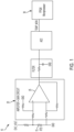
- a conventional RTD temperature measurement circuit 10 is illustrated in FIG. 1 , and utilizes a RTD 15 including a metal element such as platinum, for example, which serves as the RTD temperature sensing element.
- RTD are commonly manufactured as a platinum 100-type RTD (Pt100) or a platinum 1000-type RTD (Pt1000).
- Pt100 RTD has a nominal resistance of 100 ⁇ at ice point (e.g., 0°C)
- a Pt1000 RTD has a nominal resistance of 1,000Q at 0°C.
- Linearity of the characteristic curve, operating temperature range, and response time are the same, or substantially the same, for both a Pt100 RTD and a Pt1000 RTD.
- the temperature coefficient of resistance is also the same, or substantially the same, for both a Pt100 RTD and a Pt1000 RTD.
- the RTD 15 temperature measurement is determined based on the principle that the resistance of the metal element changes with temperature.
- the RTD 15 is located in proximity to the area where temperature is to be measured.
- An electrical voltage is applied across the RTD 15 to induce current flow through the metal element.
- the voltage across the RTD 15 is measured, and a corresponding resistance value of the metal element is then calculated using a FPGA 30 or processor 30, for example, to obtain a measured resistance of the metal element.
- This resistance value is then correlated to temperature based upon the known resistance characteristics of the metal element.
- the excitation current causes the metal sensing element to heat, thus introducing a "self-heating" effect, which can cause inaccurate or erroneous temperature measurements.
- the current level of the electrical current delivered through the metal element is reduced.
- the reduced current level also reduces the voltage level across the RTD 15. Therefore, conventional circuits employ an amplifier circuit 20 downstream from the RTD 15.
- the amplifier circuit 20 includes an amplifier 25, which amplifies the voltage across the RTD 15 to obtain voltage sufficient to determine metal element resistance.
- the amplifier 25 introduces an offset error in the measured RTD voltage thereby causing inaccurate temperature measurements.
- a conventional NTC temperature measurement circuit 50 is illustrated in FIG. 2 .
- the NTC temperature measurement circuit 50 employs an NTC thermistor 55 (referred to herein simply as an NTC 55) that serves as a temperature sensor.
- an NTC provides a low-cost solution over higher accuracy across the wide range of temperature sense compared to RTDs.
- RTDs are more accurate than NTCs in positive temperature measurements ranging 0 to 130 degrees Celsius (°C) in given application, whereas NTCs provide greater accuracy below 0 °C.
- the behavior of the NTC 55 as its resistance varies with respect to temperature changes is linear over a shorter range compared to an RTD. As shown in FIG.
- graph 70 illustrates that the NTC 55 provides an undesirable exponential relationship between resistance and temperature below 0 degrees Celsius (°C), and in particular between temperatures of about -55°C and about 130°C. This non-linear behavior also exponentially increases the error in temperature measurement, particularly for measurements in the range of about -55 degrees Celsius (°C) and about 130°C.
- NTC temperature measurement circuits typically require the need to implement an additional linearization circuit 60 (shown in FIG. 2 ) to widen the temperature measurement range of the NTC 55 for certain temperature measurement applications.
- the added linearization circuit results in a temperature measurement circuit with increased circuit complexity and costs.
- the RTD provides a significantly more linear behavior than the NTC itself (e.g., an NTC excluding the linearization circuit) and therefore does not require implementing any linearization techniques.
- a conventional NTC temperature measurement circuit 50 is not compatible with an RTD such that two separate circuit topologies are required when implementing an RTD as a temperature sensor versus implementing an NTC as a temperature sensor.
- one or more non-limiting embodiments of the present disclosure provide a ratiometric temperature measurement system configured to perform a ratio metric measurement technique that cancels and effectively removes the offset error introduced by the amplifier typically employed in conventional RTD-based and NTC-based temperature measurement circuits.
- the ratiometric temperature measurement system implements an adjustable linearization resistance element that facilitates compatibility for using either an RTD or an NTC as the temperature sensor.
- the adjustable linearization resistance element can selectively remove a resistance when utilizing an RTD as the temperature sensor and introduce a resistance when utilizing an NTC as the temperature sensor. The added resistance effectively shunts the current source to linearize the behavior of the NTC.
- the ratiometric temperature system can utilize the NTC as a temperature sensor in applications that require measurements at wider targeted temperature ranges (e.g., temperatures ranging from 50°C - 200°C).
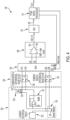
- the ratiometric temperature measurement system 100 includes a sensing circuit 102, a filter circuit 104, a multiplexer (MUX) 106, an amplifier circuit 108, an analog-to-digital converter (ADC) 110, and a controller 112.
- MUX multiplexer
- ADC analog-to-digital converter
- controller 112. the ADC 110 and controller 112 are shown as two separate and independent components, it should be appreciated that the ADC 110 and controller 112 can be implemented together as a single controller or FPGA.
- the sensing circuit 102 includes a current excitation circuit 120, a temperature sensing circuit 122, and a current sensor 124.
- the current excitation circuit 120 includes a constant current source configured to output an electrical excitation current (Io). Based on the current (Io), the sensing circuit 102 outputs a first voltage indicative of a first voltage differential (V T_SENSOR ) across the temperature sensing circuit 122 and a second voltage indicative of a second voltage differential (V C_SENSOR ) across the current sensor 124.
- the temperature sensing circuit 122 includes a temperature sensor 123 and an adjustable linearization resistance element (R p ) 125.
- the temperature sensing circuit 122 is configured to produce a voltage differential (V T_SENSOR ) that varies in response to a varying resistance of the temperature sensor 123.
- the temperature sensor 123 can include either a RTD or an NTC, each which is configured to effect the first voltage differential (V T_SENSOR ).
- a first terminal of the temperature sensor 123 can serve as an input to the sensing circuit 122 and is connected to the current sensor 124 to receive the bias current (Io).
- a second terminal of the temperature sensor 123 can serve as an output of the sensing circuit 102 and is connected to a ground potential.
- a buffer 127 (sometimes referred to as a "line buffer”) can be implemented to prevent the ground protentional from floating.
- the buffer inverting input (-) is connected to the current sensor 124
- the buffer non-inverting input (+) is connected to the ground potential
- the buffer output is connected to the second terminal of the temperature sensor 123 to provide a non-floating ground potential.
- the adjustable linearization resistance element 125 is connected in parallel with the temperature sensor 123.
- the adjustable linearization resistance element 125 includes a first terminal connected in common with the output of the current sensor 124 and the input of the temperature sensor 123.
- An opposing second terminal of the adjustable linearization resistance element 125 is connected in common with the ground potential and the output of the temperature sensor 123.
- the adjustable linearization resistance element 125 is implemented as a potentiometer or rheostat, for example, which is capable of varying (e.g., adding or removing) its resistance and therefore the resistance realized by the temperature sensor 123.
- the adjustable linearization resistance element 125 can be adjusted to set a resistance that shunts the NTC and effectively linearizes the NTC output voltage over a targeted temperature range (e.g., from about -55°C and about 130°C).
- Diagram 500 shown in FIG. 5 illustrates the resulting linearized relationship between temperature versus resistance provided by the NTC.
- the adjustable linearization resistance element 125 can be adjusted to a maximum resistance that effectively produces a virtual open circuit across the adjustable linearization resistance element 125 and in parallel with the RTD. Accordingly, the RTD effectively realizes a maximum resistance (e.g., an open circuit) in parallel and operates virtually alone without to provide a substantially linearized voltage output that is inherently produced by the RTD.
- the ratiometric temperature measurement system 100 can utilize either an NTC or a RTD as a temperature sensor 123, both which can provide a linearized relationship between temperature versus resistance over similar targeted temperature ranges (e.g., from about -55°C and about 130°C).
- the adjustable linearization resistance element 125 is a linearization resistor that be selectively connected or disconnected in parallel with the temperature sensor 123, or completely interchangeable (i.e., selectively added or removed).
- the linearization resistor has a fixed resistance that is determined (e.g., through pre-testing)) to linearize an NTC over a targeted temperature range (e.g., from about -55°C and about 130°C).
- the linearization resistance element 125 can be connected or added when an NTC is utilized as the temperature sensor 123 such that the NTC realizes the resistance set by the added linearization resistor.
- the linearization resistance element 125 can be conveniently disconnected or completely removed.
- the RTD effectively realizes a maximum resistance (e.g., an open circuit) in parallel and operates alone to provide a substantially linearized voltage output that is inherently produced by the RTD.
- the adjustable linearization resistance element 125 allows for utilizing either an NTC or a RTD as a temperature sensor 123 without requiring substantial modification of the ratiometric temperature measurement system 100.
- the current sensor 124 is in signal communication with the current excitation circuit 102 to receive the bias excitation current (Io).
- the current sensor 124 is constructed using a current sense resistor 129 that has a fixed resistance (R C_SENSE ). Accordingly, a voltage drop across the current sense resistor 129 defines the second voltage differential (V C_SENSOR ).
- the filter circuit 104 is in signal communication with the sensing circuit 102 and is configured to filter the first voltage differential (V T_SENSOR ) and the second voltage differential (V C_SENSOR ).
- the filter circuit 104 includes a first differential mode filter 130 and a second differential mode filter 132.
- a first input of the first differential mode filter 130 is connected in common with the input of the temperature sensor 123 and the output of the current sensor 124.
- a second input of the first differential mode filter 130 is connected in common with the output of the temperature sensor 123 and the ground potential.
- a first input of the second differential mode filter 132 is connected in common with the output of the current excitation circuit 120 and the input of the current sensor 124.
- a second input of the second differential mode filter 132 is connected in common with the output of the current sensor 124 and the input of the temperature sensor 123.
- the first differential mode filter 130 and the second differential mode filter 132 can each be constructed using a pair of RC filters and a capacitor that bridges the filter outputs.
- a first RC filter can be connected between the first input of the first differential mode filter 130 and the first output of the first differential mode filter 130.
- a second RC filter can be connected between the second input of the first differential mode filter 130 and the second output of the first differential mode filter 130.
- the capacitor can include a first terminal connected in common with the first RC filter and the first output and a second terminal connected in common with the second RC filter and the second output.
- the second differential mode filter 132 can include a first RC filter that is connected between the first input of the second differential mode filter 132 and the first output of the second differential mode filter 132.
- a second RC filter can be connected between the second input of the second differential mode filter 132 and the second output of the second differential mode filter 132.
- the capacitor of the second differential mode filter 132 includes a first terminal that is connected in common with the first RC filter and the first output and a second terminal connected in common with the second RC filter and the second output.
- the multiplexer (MUX) 106 is configured to selectively output the first filtered voltage differential (V T_SENSOR ) or the second filtered voltage differential (V C_SENSOR ).
- the MUX 106 includes a first temperature sensor voltage input (S1A), a second temperature sensor voltage input (S1B), a first current sensor voltage input (S2A), and a second current sensor voltage input (S2B).
- the first temperature sensor voltage input (S1A) is connected to the first output of the first differential mode filter 130.
- the second temperature sensor voltage input (S1B) is connected to the second output of the first differential mode filter 130.
- the first current sensor voltage input (S2A) is connected to the first output of the second differential mode filter 132.
- the second current sensor voltage input (S2B) is connected to the second output of the second differential mode filter 132.
- the MUX 106 further includes a first selector line input (A0), a second selector line input (A1), a first output line (DA) and a second output line (DB).
- the first selector line input (A0) and the second selector line input (A1) are each connected to the controller 112.
- the controller 112 can output control signals for selecting signals applied to the first temperature sensor voltage input (S1A) and the second temperature sensor voltage input (S1B) to be output on the first and second output lines DA and DB, respectively, or for selecting signals applied to the first temperature sensor voltage input (S1A) and the second temperature sensor voltage input (S1B) to be output on the first and second output lines DA and DB, respectively.
- the voltage differential measurement across the temperature sensor 123 and the current sensor 124 are time multiplexed with a bandwidth that is greater than 1 kilohertz (KHz) per 1 millisecond (ms). That is, the first and second temperature sensor voltage inputs (S1A and S1B) receive the voltage determined by the resistance of the temperature sensor 123, while the first and second current sensor voltage inputs (S2A and S2B) receive the voltage determined by the bias current (Io) through the current sensor 124.
- KHz kilohertz
- the controller 112 calculates a ratio of the temperature sensor voltage differential (e.g., voltage drop across the temperature sensor 123) and the current level (I exc ) of the bias current (I o ).
- the bias current (Io) can be calculated based on the voltage drop across the current sense resistor 129 and the resistance of the current sense resistor 129. As same current is passed through sense resistor and sensor, the ratio calculation cancels out the gain error while also providing the resistance of the temperature sensor 123 as described in greater detail below.
- the mechanical time constant of heat rise is typically less than 5 ms even at a 0.1 degree Celsius (°C) change in a practical case of module temperature measurements. Therefore, the ratio metric measurements performed by the ratiometric temperature measurement system 100 described herein provide very accurate results with minimized gain errors.
- the controller 112 utilizes a truth table (e.g., stored in memory) to generate the control signals used to select the pair of MUX inputs (e.g., S1A/S1B or S2A/S2B) to be output on the respective output lines DA and DB.
- the truth table can be defined as follows: Table 1 A0 A1 On Switch Pair Functionality 0 0 S1A & S1B Output first voltage differential (V T_SENSOR ) 0 1 S2A & S2B Output second filtered voltage differential (V C_SENSOR )
- the amplifier circuit 108 is in signal communication with the MUX 106 to amplify the first filtered voltage differential (V T_SENSOR ) or the second filtered voltage differential (V C_SENSOR ) selected for output by the controller 112.
- the amplifier circuit 108 includes an amplifier 140 including an inverting input (-) connected to the first MUX output line (DA) and a non-inverting input (+) connected to the second MUX output line (DB).
- the amplifier output 142 provides an amplified first filtered voltage differential (V T_SENSOR ) when the controller 112 selects the first and second temperature sensor voltage inputs (S1A and S1B), and provides an amplified second filtered voltage differential (V C_SENSOR ) when the controller 112 selects the first and second current sensor voltage inputs (S2A and S2B).
- the analog-to-digital converter (ADC) 110 is in signal communication with the output 142 of amplifier circuit 108 to convert the analog signal received from the MUX 106 into a digital output signal. Accordingly, the ADC 110 outputs a first digital signal (V oT ) indicative of the first voltage differential (V T_SENSOR ) in response to receiving the amplified first filtered voltage differential (V T_SENSOR ) and generates a second digital signal indicative (V oC ) of the second voltage differential (V C_SENSOR ) in response to receiving the amplified second filtered voltage differential (V C_SENSOR ).
- the controller 112 is in signal communication with the ADC output 150 to receive the first digital signal (V oT ) indicative of the first voltage differential (V T_SENSOR ) and the second digital signal (V oC ) indicative of the second voltage differential (V C_SENSOR ), and calculates the resistance (R T_SENSOR ) of the temperature sensor 123 based at least in part on the first and second voltage differentials (V T_SENSOR and (V C_SENSOR ). Based on the resistance (R T_SENSOR ) of the temperature sensor 123, the controller 112 determines a temperature value (T OUT ) measured by the sensing circuit 102.
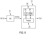
- the controller 112 is illustrated in greater detail according to a non-limiting embodiment.
- the controller 112 includes memory 200 and a processor 210.
- the memory 200 includes a look-up-table (LUT) 202 and a buffer 204.
- the LUT 202 is configured to populate a plurality of predetermined resistance values that are mapped (e.g., indexed) to corresponding predetermined temperature values.
- the buffer 204 is configured to store various values used to calculate the resistance (R T_SENSOR ) of the temperature sensor 123 and the temperature value (T OUT ) measured by the sensing circuit 102.
- the buffer 204 includes a resistance value indicative of the fixed resistance (R C_SENSE ), a value indicative of the first voltage differential (V T_SENSOR ), a value indicative of the second voltage differential (V C_SENSOR ), a value indicative of the current level (I exc ), and the calculated resistance (R T_SENSOR ).
- the processor 210 can compare the resistance (R T_SENSOR ) to the predetermined resistance values included in the LUT 202 and select a predetermined temperature value corresponding to the predetermined resistance value that matches the resistance (R T_SENSOR ). Accordingly, the controller 112 outputs the selected predetermined temperature value as the temperature value (T OUT ) that is indicative of the temperature value measured by the sensing circuit 102.
- FIGS. 7A and 7B a flow diagram depicts a method of performing a ratiometric temperature measurement according to a non-limiting embodiment.
- the method begins at operation 700 and at operation 701 a constant bias current (I o ) is generated using a current excitation circuit.
- the current (I o ) is delivered to the temperature sensing circuit.
- the ratiometric temperature measurement system 100 allows for the temperature sensor to be constructed as either a RTD or an NTC.
- a voltage differential i.e., voltage drop
- a voltage differential is induced across the temperature sensor in response to the current flowing therethrough.
- the temperature sensor voltage differential (V Tsensor ) is amplified, e.g., by an amplifier and gain circuit.
- the analog amplified temperature sensor voltage (V oT ) is converted to a digital equivalent temperature sensor voltage (V oT ).
- the back calculated temperature sensor voltage (V bT ) can be stored in memory of the controller and utilized to determine the resistance (R Tsensor ) of the temperature sensor as described in greater detail below.
- the current (Io) is delivered to the current sensor.
- the current sensor includes a current resistor that defines a resistance (R Csensor ) of the current sensor.
- a voltage differential i.e., voltage drop
- the current sensor voltage differential (V Csensor ) is amplified, e.g., by the amplifier and gain circuit.
- V oC (V Csensor ⁇ Gain), where "Gain” is the gain of the amplifier.
- the analog amplified current sensor voltage (V oC ) is converted to a digital equivalent current sensor voltage (V oC ).
- the back calculated current level (I bC ) can be stored in the memory of the controller and utilized to determine the resistance (R Tsensor ) of the temperature sensor as described in greater detail below.
- a determination is made as to whether the temperature sensor utilized in the ratiometric temperature measurement system 100 is a RTD or a NTC. When the temperature sensor is determined to be an RTD, the method proceeds to operation 718 to determine the temperature (R(t)) measured by the RTD using the equations at operation 720.
- R(t) R0+(A ⁇ T)+(B ⁇ T 2 )+(C ⁇ (100-T)) ⁇ t 3 ), where R0 is the nominal resistance value of RTD at 0°C, and values A, B and C are resistance constants as a function of temperature.
- R0 can be 100 ohms at 0°C for a platinum 100-type RTD (Pt100) and 1000 ohms at 0°C for platinum 1000-type RTD (Pt1000).
- resistance value A can be (3.9083 ⁇ 10 -3 °C- 1 )
- value B can be ((-5.775 ⁇ 10-7°C -2 )
- value C can be ((-4.183 ⁇ 10-12°C -4 ).
- R0, A, B and C are provided by the manufacturer of the RTD (e.g., the RTD data sheet provided by the manufacturer).
- the method proceeds to operation 717 to determine the temperature (R(t)) measured by the NTC using the equation at operation 719
- R25 is equal, or substantially equal, to R(t) corresponding to temperature (T).
- R25 and the value "B" can be provided by the manufacturer of the NTC (e.g., the NTC data sheet provided by the manufacturer).
- “R25” can be set at 5 k ⁇ .
- the resistance constant B can represent the exponential co-efficient for resistance variation across the measurement range, and can be set, for example, as 3433k across its range of measuring temperature" at 5 k ⁇ . Accordingly, the determined temperature (Tout) measured by the NTC is output at operation 722, and the method ends at operation 724.
- various non-limited embodiments provide a ratiometric temperature measurement system configured to perform a ratio metric measurement technique that cancels and effectively removes an offset error introduced by an amplifier gain circuit.
- the ratiometric temperature measurement system includes a sensing circuit that implements an adjustable linearization resistance element which facilitates compatibility using either an RTD or an NTC as the temperature sensor.
Landscapes
- Physics & Mathematics (AREA)
- General Physics & Mathematics (AREA)
- Nonlinear Science (AREA)
- Measuring Temperature Or Quantity Of Heat (AREA)
- Arrangements For Transmission Of Measured Signals (AREA)
Abstract
Description
- This application claims the benefit of
Indian Application No. 202211001726 filed January 12, 2022 - Embodiments of the present disclosure relate to motor control drive systems for a vehicle, and more particularly, to temperature measurement circuits employed in motor control drive system of an aircraft.
- Power switch heat sink temperature is a critical parameter to be monitored in motor control drives. Resistance temperature detectors (RTDs) and thermistors are the most used temperature sensors due to their low cost and reliability. The two types of thermistors that are typically used are Positive Temperature Coefficient (PTC) thermistors and Negative Temperature Coefficient (NTC) thermistors. While RTDs and thermistors both have resistances that vary as a function of temperature, the resistance of a PTC increases linearly in response to temperature changes compared to the resistance of an NTC which decreases linearly in response to temperature changes.
- According to a non-limiting embodiment, ratiometric temperature measurement system includes a sensing circuit to measure a temperature and a controller to determine a resistance (RT_SENSOR) corresponding to the sensing circuit. The sensing circuit includes a temperature sensing circuit and a current sensor. The sensing circuit utilize an electrical current (Io) to output a first voltage indicative of a first voltage differential (VT_SENSOR) across the temperature sensing circuit and to output a second voltage indicative of a second voltage differential (VC_SENSOR) across the current sensor. The controller is configured to determine a resistance (RT_SENSOR) corresponding to the temperature sensing circuit based at least in part on the first and second voltage differentials (VT_SENSOR and VC_SENSOR). The controller determines a temperature value (TOUT) indicative of the measured temperature based on the resistance (RT__SENSOR).
- In addition to one or more of the features described above, or as an alternative to any of the foregoing embodiments, the controller determines a current level (Iexc) of the current (Io) based on the second voltage differential (VC_SENSOR) indicated by the current sensor and a resistance (RC_SENSE) of the current sensor.
- In addition to one or more of the features described above, or as an alternative to any of the foregoing embodiments, the resistance (RT_SENSOR) of the current sensor is determined as a ratio of the first voltage differential (VT_SENSOR) to the current level (Iexc).
- In addition to one or more of the features described above, the controller comprises memory and a processor. The memory is configured to store a look-up table (LUT) populated with a plurality of predetermined resistance values that are mapped to corresponding predetermined temperature values. The processor is in signal communication with the memory. The processor is configured to compare the resistance (RT_SENSOR) of the current sensor to the predetermined resistance values, select a predetermined temperature value corresponding to the predetermined resistance value that matches the resistance (RT_SENSOR), and output the selected predetermined temperature value as the temperature value (TOUT).
- In addition to one or more of the features described above, the sensing circuit comprises a temperature sensor configured to effect the first voltage differential (VT_SENSOR) in response to the current (Io); and an adjustable linearization resistance element (Rp) configured to selectively add or remove a resistance realized by the temperature sensor.
- In addition to one or more of the features described above, the temperature sensor includes a first terminal connected to the current sensor to receive the current and a second terminal connected to a ground potential.
- In addition to one or more of the features described above, a current excitation circuit including a constant current source is configured to generate the current.
- In addition to one or more of the features described above, the current sensor is in signal communication with the current excitation circuit and is configured to effect the second voltage differential (VC_SENSOR) thereacross in response to the current.
- In addition to one or more of the features described above, the current sensor includes a current sense resistor having a fixed resistance that defines the resistance (RC_SENSE) of the current sensor.
- In addition to one or more of the features described above, a voltage drop across the sense resistor defines the second voltage differential (VC_SENSOR).
- In addition to one or more of the features described above, the system includes a multiplexer (MUX) and an amplifier circuit. Th MUX is configured to selectively output the first filtered voltage differential (VT_SENSOR) or the second filtered voltage differential (VC_SENSOR) in response to a control signal generated by the controller. The amplifier circuit is in signal communication with the MUX. The amplifier circuit is configured to amplify the first voltage differential (VT_SENSOR) and to amplify the second voltage differential (VC_SENSOR).
- In addition to one or more of the features described above, a filter circuit in signal communication with the sensing circuit, the filter circuit configured to filter the first voltage differential (VT_SENSOR) and the second voltage differential (VC_SENSOR) and output the filtered first and second voltage differentials to the amplifier circuit.
- In addition to one or more of the features described above, an analog-to-digital converter (ADC) including an input connected to the amplifier circuit and an output connected to the controller, the ADC configured to generate a first digital signal indicative (of the first voltage differential (VT_SENSOR) and a second digital signal indicative of the second voltage differential (VC_SENSOR).
- In addition to one or more of the features described above, the temperature sensor is a RTD, and the adjustable linearization resistance element is connected in parallel with the RTD so as to establish an open circuit in parallel with the RTD.
- In addition to one or more of the features described above, the temperature sensor is an NTC and the adjustable linearization resistance element is connected in parallel with the NTC to establish a targeted resistance that shunts the NTC and linearizes the first voltage differential.
- According to another non-limiting embodiment, a method of measuring a temperature is provided. The method comprises delivering an electrical current (Io) to a sensing circuit, outputting a first voltage from a temperature sensing circuit included in the sensing circuit in response to the electrical current, and outputting a second voltage from a current sensor included in the sensing circuit. The first voltage is indicative of a first voltage differential (VT_SENSOR) and the second voltage is indicative of a second voltage differential (VC_SENSOR). The method further comprises determinizing a resistance (RT_SENSOR) corresponding to the temperature sensing circuit based at least in part on the first and second voltage differentials (VT_SENSOR and VC_SENSOR). The method further comprises determining a temperature value (TOUT) indicative of the temperature based on the resistance (RT_SENSOR).
- In addition to one or more of the features described above, or as an alternative to any of the foregoing embodiments, the method further comprises determining, using the controller, a current level (Iexc) of the current (Io) based on the second voltage differential (VC_SENSOR) indicated by the current sensor and a resistance (RC_SENSE) of the current sensor.
- In addition to one or more of the features described above, or as an alternative to any of the foregoing embodiments, the method further comprises determining the resistance (RT_SENSOR) of the current sensor as a ratio of the first voltage differential (VT_SENSOR) to the current level (Iexc).
- In addition to one or more of the features described above, or as an alternative to any of the foregoing embodiments, the method further comprises selectively adding or removing a resistance realized by the temperature sensor using an adjustable linearization resistance element (Rp).
- In addition to one or more of the features described above, or as an alternative to any of the foregoing embodiments, the method further comprises populating a look-up table (LUT) with a plurality of predetermined resistance values that are mapped to corresponding predetermined temperature values; comparing, by the controller, the resistance (RT_SENSOR) of the current sensor to the predetermined resistance values; selecting, by the controller, a predetermined temperature value corresponding to the predetermined resistance value that matches the resistance (RT_SENSOR); and outputting, by the controller, the selected predetermined temperature value as the temperature value (TOUT)
- Additional features and advantages are realized through techniques described herein. Other embodiments and aspects are described in detail herein. For a better understanding, refer to the description and to the drawings.
- The following descriptions should not be considered limiting in any way. With reference to the accompanying drawings, like elements are numbered alike:
-
FIG. 1 is a block diagram of a conventional RTD temperature measurement circuit; -
FIG. 2 is a block diagram of a conventional NTC temperature measurement circuit; -
FIG. 3 is a diagram illustrating a relationship between temperature versus resistance associated with the conventional NTC temperature measurement circuit shown inFIG. 2 ; -
FIG. 4 is a block diagram of a ratiometric temperature measurement system according to a non-limiting embodiment; -
FIG. 5 is a diagram illustrating a relationship between temperature versus resistance associated with an NTC implemented in the ratiometric temperature measurement system ofFIG. 4 according to a non-limiting embodiment; -
FIG. 6 is block diagram of a controller configured to perform a ratiometric temperature measurement according to a non-limiting embodiment; and -
FIGS. 7A and7B depict a flow diagram illustrating a method of performing a ratiometric temperature measurement according to a non-limiting embodiment. - A detailed description of one or more embodiments of the disclosed apparatus and method are presented herein by way of exemplification and not limitation with reference to the Figures.
- Turning to an overview of technologies that are more specifically relevant to aspects of the present disclosure, temperature measurement circuits employed in motor control drive systems of an aircraft typically implement an RTD or a NTC to perform temperature measurements. A conventional RTD
temperature measurement circuit 10 is illustrated inFIG. 1 , and utilizes aRTD 15 including a metal element such as platinum, for example, which serves as the RTD temperature sensing element. For example, RTD are commonly manufactured as a platinum 100-type RTD (Pt100) or a platinum 1000-type RTD (Pt1000). A Pt100 RTD has a nominal resistance of 100 Ω at ice point (e.g., 0°C), while a Pt1000 RTD has a nominal resistance of 1,000Q at 0°C. Linearity of the characteristic curve, operating temperature range, and response time are the same, or substantially the same, for both a Pt100 RTD and a Pt1000 RTD. The temperature coefficient of resistance is also the same, or substantially the same, for both a Pt100 RTD and a Pt1000 RTD. - The
RTD 15 temperature measurement is determined based on the principle that the resistance of the metal element changes with temperature. In practice, theRTD 15 is located in proximity to the area where temperature is to be measured. An electrical voltage is applied across theRTD 15 to induce current flow through the metal element. The voltage across theRTD 15 is measured, and a corresponding resistance value of the metal element is then calculated using aFPGA 30 orprocessor 30, for example, to obtain a measured resistance of the metal element. This resistance value is then correlated to temperature based upon the known resistance characteristics of the metal element. The excitation current, however, causes the metal sensing element to heat, thus introducing a "self-heating" effect, which can cause inaccurate or erroneous temperature measurements. - To avoid the self-heating effect, the current level of the electrical current delivered through the metal element is reduced. The reduced current level, however, also reduces the voltage level across the
RTD 15. Therefore, conventional circuits employ anamplifier circuit 20 downstream from theRTD 15. Theamplifier circuit 20 includes anamplifier 25, which amplifies the voltage across theRTD 15 to obtain voltage sufficient to determine metal element resistance. However, theamplifier 25 introduces an offset error in the measured RTD voltage thereby causing inaccurate temperature measurements. - A conventional NTC
temperature measurement circuit 50 is illustrated inFIG. 2 . Rather than implementing an RTD, the NTCtemperature measurement circuit 50 employs an NTC thermistor 55 (referred to herein simply as an NTC 55) that serves as a temperature sensor. Using an NTC provides a low-cost solution over higher accuracy across the wide range of temperature sense compared to RTDs. For example, RTDs are more accurate than NTCs in positive temperature measurements ranging 0 to 130 degrees Celsius (°C) in given application, whereas NTCs provide greater accuracy below 0 °C. However, the behavior of theNTC 55 as its resistance varies with respect to temperature changes is linear over a shorter range compared to an RTD. As shown inFIG. 3 , for example,graph 70 illustrates that theNTC 55 provides an undesirable exponential relationship between resistance and temperature below 0 degrees Celsius (°C), and in particular between temperatures of about -55°C and about 130°C. This non-linear behavior also exponentially increases the error in temperature measurement, particularly for measurements in the range of about -55 degrees Celsius (°C) and about 130°C. - The undesired exponential behavior of convention NTC temperature measurement circuits typically require the need to implement an additional linearization circuit 60 (shown in
FIG. 2 ) to widen the temperature measurement range of theNTC 55 for certain temperature measurement applications. The added linearization circuit however, results in a temperature measurement circuit with increased circuit complexity and costs. Moreover, the RTD provides a significantly more linear behavior than the NTC itself (e.g., an NTC excluding the linearization circuit) and therefore does not require implementing any linearization techniques. As a result, a conventional NTCtemperature measurement circuit 50 is not compatible with an RTD such that two separate circuit topologies are required when implementing an RTD as a temperature sensor versus implementing an NTC as a temperature sensor. - Turning now to a more detailed description of the inventive teachings, one or more non-limiting embodiments of the present disclosure provide a ratiometric temperature measurement system configured to perform a ratio metric measurement technique that cancels and effectively removes the offset error introduced by the amplifier typically employed in conventional RTD-based and NTC-based temperature measurement circuits. In addition, the ratiometric temperature measurement system implements an adjustable linearization resistance element that facilitates compatibility for using either an RTD or an NTC as the temperature sensor. In one or more non-limiting embodiments, the adjustable linearization resistance element can selectively remove a resistance when utilizing an RTD as the temperature sensor and introduce a resistance when utilizing an NTC as the temperature sensor. The added resistance effectively shunts the current source to linearize the behavior of the NTC. In this manner, the ratiometric temperature system can utilize the NTC as a temperature sensor in applications that require measurements at wider targeted temperature ranges (e.g., temperatures ranging from 50°C - 200°C).
- With reference now to the
FIG. 4 , a ratiometrictemperature measurement system 100 is illustrated according to a non-limiting embodiment of the present disclosure. The ratiometrictemperature measurement system 100 includes asensing circuit 102, afilter circuit 104, a multiplexer (MUX) 106, anamplifier circuit 108, an analog-to-digital converter (ADC) 110, and acontroller 112. Although theADC 110 andcontroller 112 are shown as two separate and independent components, it should be appreciated that theADC 110 andcontroller 112 can be implemented together as a single controller or FPGA. - The
sensing circuit 102 includes acurrent excitation circuit 120, atemperature sensing circuit 122, and acurrent sensor 124. Thecurrent excitation circuit 120 includes a constant current source configured to output an electrical excitation current (Io). Based on the current (Io), thesensing circuit 102 outputs a first voltage indicative of a first voltage differential (VT_SENSOR) across thetemperature sensing circuit 122 and a second voltage indicative of a second voltage differential (VC_SENSOR) across thecurrent sensor 124. - The
temperature sensing circuit 122 includes atemperature sensor 123 and an adjustable linearization resistance element (Rp) 125. Thetemperature sensing circuit 122 is configured to produce a voltage differential (VT_SENSOR) that varies in response to a varying resistance of thetemperature sensor 123. Thetemperature sensor 123 can include either a RTD or an NTC, each which is configured to effect the first voltage differential (VT_SENSOR). A first terminal of thetemperature sensor 123 can serve as an input to thesensing circuit 122 and is connected to thecurrent sensor 124 to receive the bias current (Io). A second terminal of thetemperature sensor 123 can serve as an output of thesensing circuit 102 and is connected to a ground potential. - In one or more non-limiting embodiments, a buffer 127 (sometimes referred to as a "line buffer") can be implemented to prevent the ground protentional from floating. When the
buffer 127 is implemented, the buffer inverting input (-) is connected to thecurrent sensor 124, the buffer non-inverting input (+) is connected to the ground potential, and the buffer output is connected to the second terminal of thetemperature sensor 123 to provide a non-floating ground potential. - The adjustable linearization resistance element 125 is connected in parallel with the
temperature sensor 123. The adjustable linearization resistance element 125 includes a first terminal connected in common with the output of thecurrent sensor 124 and the input of thetemperature sensor 123. An opposing second terminal of the adjustable linearization resistance element 125 is connected in common with the ground potential and the output of thetemperature sensor 123. - In at least one non-limiting embodiment, the adjustable linearization resistance element 125 is implemented as a potentiometer or rheostat, for example, which is capable of varying (e.g., adding or removing) its resistance and therefore the resistance realized by the
temperature sensor 123. When an NTC is utilized as thetemperature sensor 123, for example, the adjustable linearization resistance element 125 can be adjusted to set a resistance that shunts the NTC and effectively linearizes the NTC output voltage over a targeted temperature range (e.g., from about -55°C and about 130°C). Diagram 500 shown inFIG. 5 illustrates the resulting linearized relationship between temperature versus resistance provided by the NTC. - When, however, a RTD is utilized as the
temperature sensor 123, the adjustable linearization resistance element 125 can be adjusted to a maximum resistance that effectively produces a virtual open circuit across the adjustable linearization resistance element 125 and in parallel with the RTD. Accordingly, the RTD effectively realizes a maximum resistance (e.g., an open circuit) in parallel and operates virtually alone without to provide a substantially linearized voltage output that is inherently produced by the RTD. In this manner, the ratiometrictemperature measurement system 100 can utilize either an NTC or a RTD as atemperature sensor 123, both which can provide a linearized relationship between temperature versus resistance over similar targeted temperature ranges (e.g., from about -55°C and about 130°C). - According to another non-limiting embodiment, the adjustable linearization resistance element 125 is a linearization resistor that be selectively connected or disconnected in parallel with the
temperature sensor 123, or completely interchangeable (i.e., selectively added or removed). The linearization resistor has a fixed resistance that is determined (e.g., through pre-testing)) to linearize an NTC over a targeted temperature range (e.g., from about -55°C and about 130°C). In such an example, the linearization resistance element 125 can be connected or added when an NTC is utilized as thetemperature sensor 123 such that the NTC realizes the resistance set by the added linearization resistor. When the NTC is replaced with the RTD, the linearization resistance element 125 can be conveniently disconnected or completely removed. Accordingly, the RTD effectively realizes a maximum resistance (e.g., an open circuit) in parallel and operates alone to provide a substantially linearized voltage output that is inherently produced by the RTD. In either embodiment described above, the adjustable linearization resistance element 125 allows for utilizing either an NTC or a RTD as atemperature sensor 123 without requiring substantial modification of the ratiometrictemperature measurement system 100. - The
current sensor 124 is in signal communication with thecurrent excitation circuit 102 to receive the bias excitation current (Io). In one or more non-limiting embodiments, thecurrent sensor 124 is constructed using acurrent sense resistor 129 that has a fixed resistance (RC_SENSE). Accordingly, a voltage drop across thecurrent sense resistor 129 defines the second voltage differential (VC_SENSOR). - The
filter circuit 104 is in signal communication with thesensing circuit 102 and is configured to filter the first voltage differential (VT_SENSOR) and the second voltage differential (VC_SENSOR). Thefilter circuit 104 includes a firstdifferential mode filter 130 and a seconddifferential mode filter 132. A first input of the firstdifferential mode filter 130 is connected in common with the input of thetemperature sensor 123 and the output of thecurrent sensor 124. A second input of the firstdifferential mode filter 130 is connected in common with the output of thetemperature sensor 123 and the ground potential. A first input of the seconddifferential mode filter 132 is connected in common with the output of thecurrent excitation circuit 120 and the input of thecurrent sensor 124. A second input of the seconddifferential mode filter 132 is connected in common with the output of thecurrent sensor 124 and the input of thetemperature sensor 123. - The first
differential mode filter 130 and the seconddifferential mode filter 132 can each be constructed using a pair of RC filters and a capacitor that bridges the filter outputs. For example, a first RC filter can be connected between the first input of the firstdifferential mode filter 130 and the first output of the firstdifferential mode filter 130. A second RC filter can be connected between the second input of the firstdifferential mode filter 130 and the second output of the firstdifferential mode filter 130. The capacitor can include a first terminal connected in common with the first RC filter and the first output and a second terminal connected in common with the second RC filter and the second output. - Likewise, the second
differential mode filter 132 can include a first RC filter that is connected between the first input of the seconddifferential mode filter 132 and the first output of the seconddifferential mode filter 132. A second RC filter can be connected between the second input of the seconddifferential mode filter 132 and the second output of the seconddifferential mode filter 132. The capacitor of the seconddifferential mode filter 132 includes a first terminal that is connected in common with the first RC filter and the first output and a second terminal connected in common with the second RC filter and the second output. - The multiplexer (MUX) 106 is configured to selectively output the first filtered voltage differential (VT_SENSOR) or the second filtered voltage differential (VC_SENSOR). The
MUX 106 includes a first temperature sensor voltage input (S1A), a second temperature sensor voltage input (S1B), a first current sensor voltage input (S2A), and a second current sensor voltage input (S2B). - The first temperature sensor voltage input (S1A) is connected to the first output of the first
differential mode filter 130. The second temperature sensor voltage input (S1B) is connected to the second output of the firstdifferential mode filter 130. The first current sensor voltage input (S2A) is connected to the first output of the seconddifferential mode filter 132. The second current sensor voltage input (S2B) is connected to the second output of the seconddifferential mode filter 132. - The
MUX 106 further includes a first selector line input (A0), a second selector line input (A1), a first output line (DA) and a second output line (DB). The first selector line input (A0) and the second selector line input (A1) are each connected to thecontroller 112. Thecontroller 112 can output control signals for selecting signals applied to the first temperature sensor voltage input (S1A) and the second temperature sensor voltage input (S1B) to be output on the first and second output lines DA and DB, respectively, or for selecting signals applied to the first temperature sensor voltage input (S1A) and the second temperature sensor voltage input (S1B) to be output on the first and second output lines DA and DB, respectively. In one or more non-limiting embodiments, the voltage differential measurement across thetemperature sensor 123 and thecurrent sensor 124 are time multiplexed with a bandwidth that is greater than 1 kilohertz (KHz) per 1 millisecond (ms). That is, the first and second temperature sensor voltage inputs (S1A and S1B) receive the voltage determined by the resistance of thetemperature sensor 123, while the first and second current sensor voltage inputs (S2A and S2B) receive the voltage determined by the bias current (Io) through thecurrent sensor 124. - As described in greater detail below, the
controller 112 calculates a ratio of the temperature sensor voltage differential (e.g., voltage drop across the temperature sensor 123) and the current level (Iexc) of the bias current (Io). In one or more non-limiting embodiments, the bias current (Io) can be calculated based on the voltage drop across thecurrent sense resistor 129 and the resistance of thecurrent sense resistor 129. As same current is passed through sense resistor and sensor, the ratio calculation cancels out the gain error while also providing the resistance of thetemperature sensor 123 as described in greater detail below. In addition, the mechanical time constant of heat rise is typically less than 5 ms even at a 0.1 degree Celsius (°C) change in a practical case of module temperature measurements. Therefore, the ratio metric measurements performed by the ratiometrictemperature measurement system 100 described herein provide very accurate results with minimized gain errors. - In one or more non-limiting embodiments, the
controller 112 utilizes a truth table (e.g., stored in memory) to generate the control signals used to select the pair of MUX inputs (e.g., S1A/S1B or S2A/S2B) to be output on the respective output lines DA and DB. The truth table can be defined as follows:Table 1 A0 A1 On Switch Pair Functionality 0 0 S1A & S1B Output first voltage differential (VT_SENSOR) 0 1 S2A & S2B Output second filtered voltage differential (VC_SENSOR) - As described in Table 1 above, applying a first control signal having a logic "0" to the first selector line (A0) and a second control signal having a logic "0" to the second selector line (A1) selects for output the signals applied to the first temperature sensor voltage input (S 1A) and the second temperature sensor voltage input (S1B). Accordingly, the first voltage differential (VT_SENSOR) provided by the
temperature sensing circuit 122 is output using the first and second output lines DA and DB. Applying a second control signal having a logic "0" to the first selector line (A0) and a second control signal having a logic "1" to the second selector line (A1) selects for output the signals applied to the first current sensor voltage input (S2A) and the second current sensor voltage input (S2B). Accordingly, the second voltage differential (VC_SENSOR) provided by thecurrent sensor 124 is output using the first and second output lines DA and DB. - The
amplifier circuit 108 is in signal communication with theMUX 106 to amplify the first filtered voltage differential (VT_SENSOR) or the second filtered voltage differential (VC_SENSOR) selected for output by thecontroller 112. Theamplifier circuit 108 includes anamplifier 140 including an inverting input (-) connected to the first MUX output line (DA) and a non-inverting input (+) connected to the second MUX output line (DB). Accordingly, theamplifier output 142 provides an amplified first filtered voltage differential (VT_SENSOR) when thecontroller 112 selects the first and second temperature sensor voltage inputs (S1A and S1B), and provides an amplified second filtered voltage differential (VC_SENSOR) when thecontroller 112 selects the first and second current sensor voltage inputs (S2A and S2B). - The analog-to-digital converter (ADC) 110 is in signal communication with the
output 142 ofamplifier circuit 108 to convert the analog signal received from theMUX 106 into a digital output signal. Accordingly, theADC 110 outputs a first digital signal (VoT) indicative of the first voltage differential (VT_SENSOR) in response to receiving the amplified first filtered voltage differential (VT_SENSOR) and generates a second digital signal indicative (VoC) of the second voltage differential (VC_SENSOR) in response to receiving the amplified second filtered voltage differential (VC_SENSOR). - The
controller 112 is in signal communication with theADC output 150 to receive the first digital signal (VoT) indicative of the first voltage differential (VT_SENSOR) and the second digital signal (VoC) indicative of the second voltage differential (VC_SENSOR), and calculates the resistance (RT_SENSOR) of thetemperature sensor 123 based at least in part on the first and second voltage differentials (VT_SENSOR and (VC_SENSOR). Based on the resistance (RT_SENSOR) of thetemperature sensor 123, thecontroller 112 determines a temperature value (TOUT) measured by thesensing circuit 102. - Turning to
FIG. 6 , thecontroller 112 is illustrated in greater detail according to a non-limiting embodiment. Thecontroller 112 includesmemory 200 and aprocessor 210. Thememory 200 includes a look-up-table (LUT) 202 and abuffer 204. TheLUT 202 is configured to populate a plurality of predetermined resistance values that are mapped (e.g., indexed) to corresponding predetermined temperature values. - The
buffer 204 is configured to store various values used to calculate the resistance (RT_SENSOR) of thetemperature sensor 123 and the temperature value (TOUT) measured by thesensing circuit 102. In one or more non-limiting embodiments, thebuffer 204 includes a resistance value indicative of the fixed resistance (RC_SENSE), a value indicative of the first voltage differential (VT_SENSOR), a value indicative of the second voltage differential (VC_SENSOR), a value indicative of the current level (Iexc), and the calculated resistance (RT_SENSOR). - The
processor 210 is in signal communication with thememory 200. As described herein, theprocessor 210 is configured to calculate the resistance (RT_SENSOR) of thetemperature sensor 123 based at least in part on the first and second voltage differentials (VT_SENSOR and (VC_SENSOR). For example, theprocessor 210 can determine a current level (Iexc) of the current based on the second voltage differential (VC_SENSOR) indicated by the current sensor and the fixed resistance (RC_SENSE) of the sense resistor. The resistance (RT_SENSOR) of thetemperature sensor 123 is effectively a ratio of the first voltage differential (VT_SENSOR) to the current level (Iexc). Accordingly, theprocessor 210 can calculate the resistance (RT_SENSOR) according to the equation:
- Once the resistance (RT_SENSOR) of the
temperature sensor 123 is determined, theprocessor 210 can compare the resistance (RT_SENSOR) to the predetermined resistance values included in theLUT 202 and select a predetermined temperature value corresponding to the predetermined resistance value that matches the resistance (RT_SENSOR). Accordingly, thecontroller 112 outputs the selected predetermined temperature value as the temperature value (TOUT) that is indicative of the temperature value measured by thesensing circuit 102. - Turning now to
FIGS. 7A and7B , a flow diagram depicts a method of performing a ratiometric temperature measurement according to a non-limiting embodiment. The method begins atoperation 700 and at operation 701 a constant bias current (Io) is generated using a current excitation circuit. Turning first tooperation 702, the current (Io) is delivered to the temperature sensing circuit. As described herein, the ratiometrictemperature measurement system 100 allows for the temperature sensor to be constructed as either a RTD or an NTC. At operation 704, a voltage differential (i.e., voltage drop) is induced across the temperature sensor in response to the current flowing therethrough. The voltage differential (VTsensor) across the temperature sensor can be expressed as: VTsensor = (RTsensor ∗Io), where RTsensor is the resistance corresponding to the temperature sensor. Atoperation 706, the temperature sensor voltage differential (VTsensor) is amplified, e.g., by an amplifier and gain circuit. The amplified temperature sensor voltage (VoT) can be expressed as: VoT = (VTsensor ∗Gain), where "Gain" is the gain of the amplifier included in the amplifier circuit. Atoperation 708, the analog amplified temperature sensor voltage (VoT) is converted to a digital equivalent temperature sensor voltage (VoT). Atoperation 710, a back calculated temperature sensor voltage (VbT) can be determined (e.g., by a controller) by dividing the temperature sensor voltage (VoT) by the Gain of the amplifier, and can be expressed as: VbT =( VoT *Gain). The back calculated temperature sensor voltage (VbT) can be stored in memory of the controller and utilized to determine the resistance (RTsensor) of the temperature sensor as described in greater detail below. - Turning now to
operation 703, the current (Io) is delivered to the current sensor. In one or more non-limiting embodiments, the current sensor includes a current resistor that defines a resistance (RCsensor) of the current sensor. Atoperation 705, a voltage differential (i.e., voltage drop) is induced across the current sensor in response to the current flowing therethrough. The voltage differential (VCsensor) across the current sensor can be expressed as: VCsensor = (RCsensor ∗Io), where RCsensor is the resistance corresponding to the current sensor. Atoperation 707, the current sensor voltage differential (VCsensor) is amplified, e.g., by the amplifier and gain circuit. The amplified current sensor voltage (VoC) can be expressed as: VoC = (VCsensor ∗Gain), where "Gain" is the gain of the amplifier. Atoperation 709, the analog amplified current sensor voltage (VoC) is converted to a digital equivalent current sensor voltage (VoC). Atoperation 711, a back calculated current level (IbC) of the current flowing through the current sensor can be determined (e.g., by the controller) by dividing the current sensor voltage (VoC) by a product of the current sensor resistance (RCsensor) and the Gain of the amplifier, and can be expressed as: IbC =( VoC /( RCsensor ∗Gain)). The back calculated current level (IbC) can be stored in the memory of the controller and utilized to determine the resistance (RTsensor) of the temperature sensor as described in greater detail below. - Turning to operation 714 (see
FIG. 7B ), the temperature sensor resistance (RTsensor) is determined as a ratio between the back calculated temperature sensor voltage (VbT) and the back calculated current level (IbC). As described herein, the controller can calculate the temperature sensor resistance (RTsensor) according to the expression: RTsensor = (VbT / IbC). Atoperation 716, a determination is made as to whether the temperature sensor utilized in the ratiometrictemperature measurement system 100 is a RTD or a NTC. When the temperature sensor is determined to be an RTD, the method proceeds tooperation 718 to determine the temperature (R(t)) measured by the RTD using the equations atoperation 720. When measuring temperatures below 0°C (i.e., T<0), a first equation is used: R(t)=R0+(A∗T)+(B∗T2)+(C∗(100-T))∗t3), where R0 is the nominal resistance value of RTD at 0°C, and values A, B and C are resistance constants as a function of temperature. For example, R0 can be 100 ohms at 0°C for a platinum 100-type RTD (Pt100) and 1000 ohms at 0°C for platinum 1000-type RTD (Pt1000). The resistance values can be set, for example, as follow: resistance value A can be (3.9083∗10-3°C-1), value B can be ((-5.775∗10-7°C-2), and value C can be ((-4.183∗10-12°C-4). In one or more non-limiting embodiments, R0, A, B and C are provided by the manufacturer of the RTD (e.g., the RTD data sheet provided by the manufacturer). - When measuring temperatures (R(t)) above 0 °C (i.e., T>0), however, a second equation is used: R(t) = R0+(A∗T)+(B∗T2). Accordingly, the determined temperature (Tout) measured by the RTD is output at
operation 722, and the method ends atoperation 724. - When, however, the temperature sensor is determined to be an NTC at
operation 716, the method proceeds tooperation 717 to determine the temperature (R(t)) measured by the NTC using the equation atoperation 719 According to a non-limiting embodiment, the equation used by the NTC includes:
- In one or more non-limiting embodiments, R25 and the value "B" can be provided by the manufacturer of the NTC (e.g., the NTC data sheet provided by the manufacturer). For example, "R25" can be set at 5 kΩ. The resistance constant B can represent the exponential co-efficient for resistance variation across the measurement range, and can be set, for example, as 3433k across its range of measuring temperature" at 5 kΩ. Accordingly, the determined temperature (Tout) measured by the NTC is output at
operation 722, and the method ends atoperation 724. - As described herein, various non-limited embodiments provide a ratiometric temperature measurement system configured to perform a ratio metric measurement technique that cancels and effectively removes an offset error introduced by an amplifier gain circuit. In addition, the ratiometric temperature measurement system includes a sensing circuit that implements an adjustable linearization resistance element which facilitates compatibility using either an RTD or an NTC as the temperature sensor.
- The terminology used herein is for the purpose of describing particular embodiments only and is not intended to be limiting of the present disclosure. As used herein, the singular forms "a", "an" and "the" are intended to include the plural forms as well, unless the context clearly indicates otherwise. It will be further understood that the terms "comprises" and/or "comprising," when used in this specification, specify the presence of stated features, integers, steps, operations, elements, and/or components, but do not preclude the presence or addition of one or more other features, integers, steps, operations, element components, and/or groups thereof. The term "about" is intended to include the degree of error associated with measurement of the particular quantity based upon the equipment available at the time of filing the application.
- While the present disclosure has been described with reference to an exemplary embodiment or embodiments, it will be understood by those skilled in the art that various changes may be made and equivalents may be substituted for elements thereof without departing from the scope of the present disclosure. In addition, many modifications may be made to adapt a particular situation or material to the teachings of the present disclosure without departing from the essential scope thereof. Therefore, it is intended that the present disclosure not be limited to the particular embodiment disclosed as the best mode contemplated for carrying out this present disclosure, but that the present disclosure will include all embodiments falling within the scope of the claims.
Claims (15)
- A ratiometric temperature measurement system (100) comprising:a sensing circuit (102) configured to measure a temperature, the sensing circuit including a temperature sensing circuit (122) and a current sensor (124), the sensing circuit configured to utilize an electrical current (Io) to output a first voltage indicative of a first voltage differential (VT_SENSOR) across the temperature sensing circuit and to output a second voltage indicative of a second voltage differential (VC_SENSOR) across the current sensor; anda controller (112) configured to determine a resistance (RT_SENSOR) corresponding to the temperature sensing circuit based at least in part on the first and second voltage differentials (VT_SENSOR and (VC_SENSOR), and to determine a temperature value (TOUT) indicative of the measured temperature based on the resistance (RT_SENSOR).
- The ratiometric temperature measurement system (100) of claim 1, wherein the controller (112) determines a current level (Iexc) of the current (Io) based on the second voltage differential (VC_SENSOR) indicated by the current sensor (124) and a resistance (RC_SENSE) of the current sensor.
- The ratiometric temperature measurement system (100) of claim 2, wherein the resistance (RT_SENSOR) of the current sensor (124) is determined as a ratio of the first voltage differential (VT_SENSOR) to the current level (Iexc).
- The ratiometric temperature measurement system (100) of claim 3, wherein the controller (112) comprises:memory (200) configured to store a look-up table (LUT) populated with a plurality of predetermined resistance values that are mapped to corresponding predetermined temperature values; anda processor (210) in signal communication with the memory, the processor configured to compare the resistance (RT_SENSOR) of the current sensor to the predetermined resistance values, select a predetermined temperature value corresponding to the predetermined resistance value that matches the resistance (RT_SENSOR), and output the selected predetermined temperature value as the temperature value (TOUT).
- The ratiometric temperature measurement system (100) of claim 3 or 4, wherein the sensing circuit (102) comprises:a temperature sensor (123) configured to effect the first voltage differential (VT_SENSOR) in response to the current (Io); andan adjustable linearization resistance element (Rp) configured to selectively add or remove a resistance realized by the temperature sensor.
- The ratiometric temperature measurement system (100) of claim 5, wherein the temperature sensor (123) includes a first terminal connected to the current sensor to receive the current and a second terminal connected to a ground potential.
- The ratiometric temperature measurement system (100) of claim 6, further comprising a current excitation circuit (120) including a constant current source configured to generate the current.
- The ratiometric temperature measurement system (100) of claim 7, wherein the current sensor (124) is in signal communication with the current excitation circuit (120) and is configured to effect the second voltage differential (VC_SENSOR) thereacross in response to the current.
- The ratiometric temperature measurement system (100) of claim 8, wherein the current sensor (124) includes a current sense resistor (129) having a fixed resistance that defines the resistance (RC_SENSE) of the current sensor
- The ratiometric temperature measurement system (100) of claim 9, wherein a voltage drop across the sense resistor defines the second voltage differential (VC_SENSOR).
- The ratiometric temperature measurement system (100) of claim 10, further comprising:a multiplexer, MUX, (106) configured to selectively output the first filtered voltage differential (VT_SENSOR) or the second filtered voltage differential (VC_SENSOR) in response to a control signal generated by the controller; andan amplifier circuit (108) in signal communication with the MUX, the amplifier circuit configured to amplify the first voltage differential (VT_SENSOR) and to amplify the second voltage differential (VC_SENSOR); optionallyfurther comprising a filter circuit (104) in signal communication with the sensing circuit (102), the filter circuit configured to filter the first voltage differential (VT_SENSOR) and the second voltage differential (VC_SENSOR) and output the filtered first and second voltage differentials to the amplifier circuit, and further optionallyfurther comprising an analog-to-digital converter, ADC, (110) including an input connected to the amplifier circuit and an output connected to the controller, the ADC configured to generate a first digital signal indicative of the first voltage differential (VT_SENSOR) and a second digital signal indicative of the second voltage differential (VC_SENSOR).
- The ratiometric temperature measurement system of any of claims 6 to 11, wherein the temperature sensor (123) is a RTD, and the adjustable linearization resistance element is connected in parallel with the RTD so as to establish an open circuit in parallel with the RTD; or
wherein the temperature sensor is an NTC and the adjustable linearization resistance element is connected in parallel with the NTC to establish a targeted resistance that shunts the NTC and linearizes the first voltage differential. - A method (700) of measuring a temperature, the method comprising:delivering an electrical current (Io) to a sensing circuit;outputting a first voltage from a temperature sensing circuit included in the sensing circuit in response to the electrical current, the first voltage indicative of a first voltage differential (VT_SENSOR);outputting a second voltage from a current sensor included in the sensing circuit, the second voltage indicative of a second voltage differential (VC_SENSOR); anddeterminizing, using a controller, a resistance (RT_SENSOR) corresponding to the temperature sensing circuit based at least in part on the first and second voltage differentials (VT_SENSOR and (VC_SENSOR); anddetermining, using the controller, a temperature value (TOUT) indicative of the temperature based on the resistance (RT_SENSOR).
- The method of claim 13, determining, using the controller, a current level (Iexc) of the current (Io) based on the second voltage differential (VC_SENSOR) 15 by the current sensor and a resistance (RC_SENSE) of the current sensor.
- The method of claim 14, determining the resistance (RT_SENSOR) of the current sensor as a ratio of the first voltage differential (VT_SENSOR) to the current level (Iexc); optionallyfurther comprising selectively adding or removing a resistance realized by the temperature sensor using an adjustable linearization resistance element (Rp), and further optionallypopulating a look-up table (LUT) with a plurality of predetermined resistance values that are mapped to corresponding predetermined temperature values;comparing, by the controller, the resistance (RT_SENSOR) of the current sensor to the predetermined resistance values;selecting, by the controller, a predetermined temperature value corresponding to the predetermined resistance value that matches the resistance (RT_SENSOR); andoutputting, by the controller, the selected predetermined temperature value as the temperature value (TOUT).
Applications Claiming Priority (1)
| Application Number | Priority Date | Filing Date | Title |
|---|---|---|---|
| IN202211001726 | 2022-01-12 |
Publications (2)
| Publication Number | Publication Date |
|---|---|
| EP4215889A1 true EP4215889A1 (en) | 2023-07-26 |
| EP4215889B1 EP4215889B1 (en) | 2026-03-18 |
Family
ID=84943766
Family Applications (1)
| Application Number | Title | Priority Date | Filing Date |
|---|---|---|---|
| EP23151309.4A Active EP4215889B1 (en) | 2022-01-12 | 2023-01-12 | Common signal conditioning circuit for temperature sensor |
Country Status (4)
| Country | Link |
|---|---|
| US (1) | US12264977B2 (en) |
| EP (1) | EP4215889B1 (en) |
| BR (1) | BR102023000471A2 (en) |
| CA (1) | CA3185885A1 (en) |
Citations (3)
| Publication number | Priority date | Publication date | Assignee | Title |
|---|---|---|---|---|
| US20040125857A1 (en) * | 2002-12-30 | 2004-07-01 | Sprock Douglas A. | Method and apparatus to sense temperature of thermal tuning elements in tunable optical devices |
| US20100177800A1 (en) * | 2009-01-09 | 2010-07-15 | Rosemount Inc. | Process temperature transmitter with improved temperature calculation |
| US20110264001A1 (en) * | 2009-01-19 | 2011-10-27 | Koninklijke Philips Electronics N.V. | Zero heat flux sensor and method of use |
Family Cites Families (19)
| Publication number | Priority date | Publication date | Assignee | Title |
|---|---|---|---|---|
| US4050309A (en) * | 1974-11-04 | 1977-09-27 | William Wahl Corporation | Method and apparatus for measuring temperature |
| US5116136A (en) | 1989-06-01 | 1992-05-26 | Massachusetts Institute Of Technology | Temperature measurements using thermistor elements |
| US5030849A (en) | 1989-06-30 | 1991-07-09 | Analog Devices, Inc. | Monolithic ratiometric temperature measurement circuit |
| US5345064A (en) | 1992-09-08 | 1994-09-06 | Appliance Control Technology, Inc. | Temperature probe conditioner circuit |
| WO1995000825A1 (en) | 1993-06-22 | 1995-01-05 | Honeywell Inc. | Dual matching current sink total temperature circuit |
| DE59409796D1 (en) | 1994-11-11 | 2001-08-09 | Endress Hauser Gmbh Co | Arrangement for linearization and temperature compensation of sensor signals |
| US5700090A (en) | 1996-01-03 | 1997-12-23 | Rosemount Inc. | Temperature sensor transmitter with sensor sheath lead |
| US6928379B2 (en) | 2002-06-21 | 2005-08-09 | Emerson Electric Co. | Apparatus and method for sensing temperature |
| US6910804B2 (en) * | 2003-09-09 | 2005-06-28 | Schweitzer Engineering Laboratories, Inc. | Resistive temperature device (RTD) module with improved noise immunity |
| US7173414B2 (en) | 2004-10-18 | 2007-02-06 | Honeywell International Inc. | Position detection apparatus and method for linear and rotary sensing applications |
| US8529126B2 (en) | 2009-06-11 | 2013-09-10 | Rosemount Inc. | Online calibration of a temperature measurement point |
| WO2013057630A1 (en) | 2011-10-21 | 2013-04-25 | University Of Manitoba | Passive wireless sensor |
| CN102589741B (en) * | 2012-03-14 | 2014-01-01 | 华为终端有限公司 | A temperature detection method and device |
| JP6092129B2 (en) * | 2014-01-16 | 2017-03-08 | アズビル株式会社 | Temperature measuring system and temperature measuring instrument |
| US9391630B2 (en) | 2014-06-13 | 2016-07-12 | Hamilton Sundstrand Corporation | Multiplexed signal sampler and conditioner |
| US9835575B2 (en) | 2014-10-16 | 2017-12-05 | Ams International Ag | Ratiometric device |
| US10054965B2 (en) | 2015-08-06 | 2018-08-21 | Honeywell International Inc. | Analog/digital input architecture having programmable analog output mode |
| US11119134B2 (en) | 2019-08-02 | 2021-09-14 | Cirrus Logic, Inc. | Detector and method for measuring a resistance of a variable resistance sensor whose resistance varies with respect to a time-varying stimulus |
| US10972088B1 (en) | 2020-09-01 | 2021-04-06 | Infineon Technologies Ag | Temperature detection of a power switch based on paired measurements of current and voltage |
-
2022
- 2022-03-09 US US17/690,465 patent/US12264977B2/en active Active
-
2023
- 2023-01-04 CA CA3185885A patent/CA3185885A1/en active Pending
- 2023-01-10 BR BR102023000471-7A patent/BR102023000471A2/en unknown
- 2023-01-12 EP EP23151309.4A patent/EP4215889B1/en active Active
Patent Citations (3)
| Publication number | Priority date | Publication date | Assignee | Title |
|---|---|---|---|---|
| US20040125857A1 (en) * | 2002-12-30 | 2004-07-01 | Sprock Douglas A. | Method and apparatus to sense temperature of thermal tuning elements in tunable optical devices |
| US20100177800A1 (en) * | 2009-01-09 | 2010-07-15 | Rosemount Inc. | Process temperature transmitter with improved temperature calculation |
| US20110264001A1 (en) * | 2009-01-19 | 2011-10-27 | Koninklijke Philips Electronics N.V. | Zero heat flux sensor and method of use |
Non-Patent Citations (1)
| Title |
|---|
| REVERTER FERRAN: "A Tutorial on Thermal Sensors in the 200th Anniversary of the Seebeck Effect", IEEE SENSORS JOURNAL, IEEE, USA, vol. 21, no. 20, 16 August 2021 (2021-08-16), pages 22122 - 22132, XP011884399, ISSN: 1530-437X, [retrieved on 20211018], DOI: 10.1109/JSEN.2021.3105546 * |
Also Published As
| Publication number | Publication date |
|---|---|
| EP4215889B1 (en) | 2026-03-18 |
| BR102023000471A2 (en) | 2023-09-26 |
| CA3185885A1 (en) | 2023-07-12 |
| US20230221189A1 (en) | 2023-07-13 |
| US12264977B2 (en) | 2025-04-01 |
Similar Documents
| Publication | Publication Date | Title |
|---|---|---|
| US7054767B2 (en) | Thermal mass flowmeter apparatus and method with temperature correction | |
| EP0533389B1 (en) | Amplified pressure transducer | |
| US7077004B2 (en) | Method and device for measuring humidity | |
| US5193393A (en) | Pressure sensor circuit | |
| US11604100B2 (en) | Temperature sensor module | |
| EP1441206B1 (en) | Sensor temperature control in a thermal anemometer | |
| EP2128579B1 (en) | Arrangement for linearizing a non-linear sensor | |
| US8314623B2 (en) | System and method for more accurate temperature sensing using thermistors | |
| JPH0862055A (en) | Method and equipment for thermometry | |
| WO2022130210A1 (en) | A temperature sensing system with thermistor | |
| WO2017158373A1 (en) | Temperature measurement | |
| US6813570B2 (en) | Optimized convection based mass airflow sensor circuit | |
| KR100384355B1 (en) | Method of measuring temperature using negative temperature coefficient sensor and related devices | |
| US6763711B1 (en) | Air flow sensor using measurement of rate of heat loss | |
| EP0431145A1 (en) | Monolithic ratiometric temperature measurement circuit. | |
| EP4215889B1 (en) | Common signal conditioning circuit for temperature sensor | |
| JP2022503677A (en) | Temperature sensor calibration | |
| JP5437654B2 (en) | Temperature measuring device | |
| US2960866A (en) | System for measuring thermalgradients and the like | |
| US20250297976A1 (en) | Gas sensor | |
| White | The linearisation of resistance thermometers | |
| JP2965808B2 (en) | Eddy detection circuit | |
| JPS5810124Y2 (en) | heat flow meter | |
| JP2002005754A (en) | RTD measurement circuit | |
| GB2107877A (en) | Measuring temperatures electrically |
Legal Events
| Date | Code | Title | Description |
|---|---|---|---|
| PUAI | Public reference made under article 153(3) epc to a published international application that has entered the european phase |
Free format text: ORIGINAL CODE: 0009012 |
|
| STAA | Information on the status of an ep patent application or granted ep patent |
Free format text: STATUS: THE APPLICATION HAS BEEN PUBLISHED |
|
| AK | Designated contracting states |
Kind code of ref document: A1 Designated state(s): AL AT BE BG CH CY CZ DE DK EE ES FI FR GB GR HR HU IE IS IT LI LT LU LV MC ME MK MT NL NO PL PT RO RS SE SI SK SM TR |
|
| STAA | Information on the status of an ep patent application or granted ep patent |
Free format text: STATUS: REQUEST FOR EXAMINATION WAS MADE |
|
| 17P | Request for examination filed |
Effective date: 20240125 |
|
| RBV | Designated contracting states (corrected) |
Designated state(s): AL AT BE BG CH CY CZ DE DK EE ES FI FR GB GR HR HU IE IS IT LI LT LU LV MC ME MK MT NL NO PL PT RO RS SE SI SK SM TR |
|
| GRAP | Despatch of communication of intention to grant a patent |
Free format text: ORIGINAL CODE: EPIDOSNIGR1 |
|
| STAA | Information on the status of an ep patent application or granted ep patent |
Free format text: STATUS: GRANT OF PATENT IS INTENDED |
|
| RIC1 | Information provided on ipc code assigned before grant |
Ipc: G01K 7/24 20060101AFI20250905BHEP Ipc: G01K 7/20 20060101ALI20250905BHEP |
|
| INTG | Intention to grant announced |
Effective date: 20251009 |
|
| GRAS | Grant fee paid |
Free format text: ORIGINAL CODE: EPIDOSNIGR3 |
|
| GRAA | (expected) grant |
Free format text: ORIGINAL CODE: 0009210 |
|
| STAA | Information on the status of an ep patent application or granted ep patent |
Free format text: STATUS: THE PATENT HAS BEEN GRANTED |
|
| AK | Designated contracting states |
Kind code of ref document: B1 Designated state(s): AL AT BE BG CH CY CZ DE DK EE ES FI FR GB GR HR HU IE IS IT LI LT LU LV MC ME MK MT NL NO PL PT RO RS SE SI SK SM TR |
|
| REG | Reference to a national code |
Ref country code: CH Ref legal event code: F10 Free format text: ST27 STATUS EVENT CODE: U-0-0-F10-F00 (AS PROVIDED BY THE NATIONAL OFFICE) Effective date: 20260318 Ref country code: GB Ref legal event code: FG4D |
|
| REG | Reference to a national code |
Ref country code: IE Ref legal event code: FG4D |
|
| REG | Reference to a national code |
Ref country code: DE Ref legal event code: R096 Ref document number: 602023013557 Country of ref document: DE |