EP4215851A1 - Transformable refrigerated cargo containers - Google Patents
Transformable refrigerated cargo containers Download PDFInfo
- Publication number
- EP4215851A1 EP4215851A1 EP23152539.5A EP23152539A EP4215851A1 EP 4215851 A1 EP4215851 A1 EP 4215851A1 EP 23152539 A EP23152539 A EP 23152539A EP 4215851 A1 EP4215851 A1 EP 4215851A1
- Authority
- EP
- European Patent Office
- Prior art keywords
- transformable
- container body
- main container
- cargo
- assembly
- Prior art date
- Legal status (The legal status is an assumption and is not a legal conclusion. Google has not performed a legal analysis and makes no representation as to the accuracy of the status listed.)
- Granted
Links
Images








Classifications
-
- B—PERFORMING OPERATIONS; TRANSPORTING
- B65—CONVEYING; PACKING; STORING; HANDLING THIN OR FILAMENTARY MATERIAL
- B65D—CONTAINERS FOR STORAGE OR TRANSPORT OF ARTICLES OR MATERIALS, e.g. BAGS, BARRELS, BOTTLES, BOXES, CANS, CARTONS, CRATES, DRUMS, JARS, TANKS, HOPPERS, FORWARDING CONTAINERS; ACCESSORIES, CLOSURES, OR FITTINGS THEREFOR; PACKAGING ELEMENTS; PACKAGES
- B65D88/00—Large containers
- B65D88/74—Large containers having means for heating, cooling, aerating or other conditioning of contents
-
- F—MECHANICAL ENGINEERING; LIGHTING; HEATING; WEAPONS; BLASTING
- F25—REFRIGERATION OR COOLING; COMBINED HEATING AND REFRIGERATION SYSTEMS; HEAT PUMP SYSTEMS; MANUFACTURE OR STORAGE OF ICE; LIQUEFACTION SOLIDIFICATION OF GASES
- F25D—REFRIGERATORS; COLD ROOMS; ICE-BOXES; COOLING OR FREEZING APPARATUS NOT OTHERWISE PROVIDED FOR
- F25D11/00—Self-contained movable devices, e.g. domestic refrigerators
- F25D11/003—Transport containers
-
- B—PERFORMING OPERATIONS; TRANSPORTING
- B65—CONVEYING; PACKING; STORING; HANDLING THIN OR FILAMENTARY MATERIAL
- B65D—CONTAINERS FOR STORAGE OR TRANSPORT OF ARTICLES OR MATERIALS, e.g. BAGS, BARRELS, BOTTLES, BOXES, CANS, CARTONS, CRATES, DRUMS, JARS, TANKS, HOPPERS, FORWARDING CONTAINERS; ACCESSORIES, CLOSURES, OR FITTINGS THEREFOR; PACKAGING ELEMENTS; PACKAGES
- B65D90/00—Component parts, details or accessories for large containers
- B65D90/02—Wall construction
- B65D90/06—Coverings, e.g. for insulating purposes
-
- B—PERFORMING OPERATIONS; TRANSPORTING
- B64—AIRCRAFT; AVIATION; COSMONAUTICS
- B64D—EQUIPMENT FOR FITTING IN OR TO AIRCRAFT; FLIGHT SUITS; PARACHUTES; ARRANGEMENT OR MOUNTING OF POWER PLANTS OR PROPULSION TRANSMISSIONS IN AIRCRAFT
- B64D9/00—Equipment for handling freight; Equipment for facilitating passenger embarkation or the like
- B64D9/003—Devices for retaining pallets or freight containers
-
- B—PERFORMING OPERATIONS; TRANSPORTING
- B65—CONVEYING; PACKING; STORING; HANDLING THIN OR FILAMENTARY MATERIAL
- B65D—CONTAINERS FOR STORAGE OR TRANSPORT OF ARTICLES OR MATERIALS, e.g. BAGS, BARRELS, BOTTLES, BOXES, CANS, CARTONS, CRATES, DRUMS, JARS, TANKS, HOPPERS, FORWARDING CONTAINERS; ACCESSORIES, CLOSURES, OR FITTINGS THEREFOR; PACKAGING ELEMENTS; PACKAGES
- B65D88/00—Large containers
- B65D88/005—Large containers of variable capacity, e.g. with movable or adjustable walls or wall parts, modular
-
- B—PERFORMING OPERATIONS; TRANSPORTING
- B65—CONVEYING; PACKING; STORING; HANDLING THIN OR FILAMENTARY MATERIAL
- B65D—CONTAINERS FOR STORAGE OR TRANSPORT OF ARTICLES OR MATERIALS, e.g. BAGS, BARRELS, BOTTLES, BOXES, CANS, CARTONS, CRATES, DRUMS, JARS, TANKS, HOPPERS, FORWARDING CONTAINERS; ACCESSORIES, CLOSURES, OR FITTINGS THEREFOR; PACKAGING ELEMENTS; PACKAGES
- B65D88/00—Large containers
- B65D88/02—Large containers rigid
- B65D88/12—Large containers rigid specially adapted for transport
- B65D88/14—Large containers rigid specially adapted for transport by air
-
- B—PERFORMING OPERATIONS; TRANSPORTING
- B65—CONVEYING; PACKING; STORING; HANDLING THIN OR FILAMENTARY MATERIAL
- B65D—CONTAINERS FOR STORAGE OR TRANSPORT OF ARTICLES OR MATERIALS, e.g. BAGS, BARRELS, BOTTLES, BOXES, CANS, CARTONS, CRATES, DRUMS, JARS, TANKS, HOPPERS, FORWARDING CONTAINERS; ACCESSORIES, CLOSURES, OR FITTINGS THEREFOR; PACKAGING ELEMENTS; PACKAGES
- B65D88/00—Large containers
- B65D88/74—Large containers having means for heating, cooling, aerating or other conditioning of contents
- B65D88/745—Large containers having means for heating, cooling, aerating or other conditioning of contents blowing or injecting heating, cooling or other conditioning fluid inside the container
-
- B—PERFORMING OPERATIONS; TRANSPORTING
- B65—CONVEYING; PACKING; STORING; HANDLING THIN OR FILAMENTARY MATERIAL
- B65D—CONTAINERS FOR STORAGE OR TRANSPORT OF ARTICLES OR MATERIALS, e.g. BAGS, BARRELS, BOTTLES, BOXES, CANS, CARTONS, CRATES, DRUMS, JARS, TANKS, HOPPERS, FORWARDING CONTAINERS; ACCESSORIES, CLOSURES, OR FITTINGS THEREFOR; PACKAGING ELEMENTS; PACKAGES
- B65D90/00—Component parts, details or accessories for large containers
- B65D90/0006—Coupling devices between containers, e.g. ISO-containers
-
- B—PERFORMING OPERATIONS; TRANSPORTING
- B65—CONVEYING; PACKING; STORING; HANDLING THIN OR FILAMENTARY MATERIAL
- B65D—CONTAINERS FOR STORAGE OR TRANSPORT OF ARTICLES OR MATERIALS, e.g. BAGS, BARRELS, BOTTLES, BOXES, CANS, CARTONS, CRATES, DRUMS, JARS, TANKS, HOPPERS, FORWARDING CONTAINERS; ACCESSORIES, CLOSURES, OR FITTINGS THEREFOR; PACKAGING ELEMENTS; PACKAGES
- B65D90/00—Component parts, details or accessories for large containers
- B65D90/12—Supports
-
- F—MECHANICAL ENGINEERING; LIGHTING; HEATING; WEAPONS; BLASTING
- F25—REFRIGERATION OR COOLING; COMBINED HEATING AND REFRIGERATION SYSTEMS; HEAT PUMP SYSTEMS; MANUFACTURE OR STORAGE OF ICE; LIQUEFACTION SOLIDIFICATION OF GASES
- F25D—REFRIGERATORS; COLD ROOMS; ICE-BOXES; COOLING OR FREEZING APPARATUS NOT OTHERWISE PROVIDED FOR
- F25D19/00—Arrangement or mounting of refrigeration units with respect to devices or objects to be refrigerated, e.g. infrared detectors
- F25D19/003—Arrangement or mounting of refrigeration units with respect to devices or objects to be refrigerated, e.g. infrared detectors with respect to movable containers
-
- F—MECHANICAL ENGINEERING; LIGHTING; HEATING; WEAPONS; BLASTING
- F25—REFRIGERATION OR COOLING; COMBINED HEATING AND REFRIGERATION SYSTEMS; HEAT PUMP SYSTEMS; MANUFACTURE OR STORAGE OF ICE; LIQUEFACTION SOLIDIFICATION OF GASES
- F25D—REFRIGERATORS; COLD ROOMS; ICE-BOXES; COOLING OR FREEZING APPARATUS NOT OTHERWISE PROVIDED FOR
- F25D29/00—Arrangement or mounting of control or safety devices
- F25D29/003—Arrangement or mounting of control or safety devices for movable devices
-
- F—MECHANICAL ENGINEERING; LIGHTING; HEATING; WEAPONS; BLASTING
- F25—REFRIGERATION OR COOLING; COMBINED HEATING AND REFRIGERATION SYSTEMS; HEAT PUMP SYSTEMS; MANUFACTURE OR STORAGE OF ICE; LIQUEFACTION SOLIDIFICATION OF GASES
- F25D—REFRIGERATORS; COLD ROOMS; ICE-BOXES; COOLING OR FREEZING APPARATUS NOT OTHERWISE PROVIDED FOR
- F25D3/00—Devices using other cold materials; Devices using cold-storage bodies
- F25D3/12—Devices using other cold materials; Devices using cold-storage bodies using solidified gases, e.g. carbon-dioxide snow
- F25D3/125—Movable containers
-
- F—MECHANICAL ENGINEERING; LIGHTING; HEATING; WEAPONS; BLASTING
- F25—REFRIGERATION OR COOLING; COMBINED HEATING AND REFRIGERATION SYSTEMS; HEAT PUMP SYSTEMS; MANUFACTURE OR STORAGE OF ICE; LIQUEFACTION SOLIDIFICATION OF GASES
- F25B—REFRIGERATION MACHINES, PLANTS OR SYSTEMS; COMBINED HEATING AND REFRIGERATION SYSTEMS; HEAT PUMP SYSTEMS
- F25B2400/00—Component parts or details not otherwise provided for in this subclass
- F25B2400/01—Heaters
-
- F—MECHANICAL ENGINEERING; LIGHTING; HEATING; WEAPONS; BLASTING
- F25—REFRIGERATION OR COOLING; COMBINED HEATING AND REFRIGERATION SYSTEMS; HEAT PUMP SYSTEMS; MANUFACTURE OR STORAGE OF ICE; LIQUEFACTION SOLIDIFICATION OF GASES
- F25B—REFRIGERATION MACHINES, PLANTS OR SYSTEMS; COMBINED HEATING AND REFRIGERATION SYSTEMS; HEAT PUMP SYSTEMS
- F25B2400/00—Component parts or details not otherwise provided for in this subclass
- F25B2400/06—Several compression cycles arranged in parallel
-
- F—MECHANICAL ENGINEERING; LIGHTING; HEATING; WEAPONS; BLASTING
- F25—REFRIGERATION OR COOLING; COMBINED HEATING AND REFRIGERATION SYSTEMS; HEAT PUMP SYSTEMS; MANUFACTURE OR STORAGE OF ICE; LIQUEFACTION SOLIDIFICATION OF GASES
- F25D—REFRIGERATORS; COLD ROOMS; ICE-BOXES; COOLING OR FREEZING APPARATUS NOT OTHERWISE PROVIDED FOR
- F25D17/00—Arrangements for circulating cooling fluids; Arrangements for circulating gas, e.g. air, within refrigerated spaces
- F25D17/04—Arrangements for circulating cooling fluids; Arrangements for circulating gas, e.g. air, within refrigerated spaces for circulating air, e.g. by convection
- F25D17/06—Arrangements for circulating cooling fluids; Arrangements for circulating gas, e.g. air, within refrigerated spaces for circulating air, e.g. by convection by forced circulation
- F25D17/08—Arrangements for circulating cooling fluids; Arrangements for circulating gas, e.g. air, within refrigerated spaces for circulating air, e.g. by convection by forced circulation using ducts
-
- F—MECHANICAL ENGINEERING; LIGHTING; HEATING; WEAPONS; BLASTING
- F25—REFRIGERATION OR COOLING; COMBINED HEATING AND REFRIGERATION SYSTEMS; HEAT PUMP SYSTEMS; MANUFACTURE OR STORAGE OF ICE; LIQUEFACTION SOLIDIFICATION OF GASES
- F25D—REFRIGERATORS; COLD ROOMS; ICE-BOXES; COOLING OR FREEZING APPARATUS NOT OTHERWISE PROVIDED FOR
- F25D2400/00—General features of, or devices for refrigerators, cold rooms, ice-boxes, or for cooling or freezing apparatus not covered by any other subclass
- F25D2400/02—Refrigerators including a heater
-
- F—MECHANICAL ENGINEERING; LIGHTING; HEATING; WEAPONS; BLASTING
- F25—REFRIGERATION OR COOLING; COMBINED HEATING AND REFRIGERATION SYSTEMS; HEAT PUMP SYSTEMS; MANUFACTURE OR STORAGE OF ICE; LIQUEFACTION SOLIDIFICATION OF GASES
- F25D—REFRIGERATORS; COLD ROOMS; ICE-BOXES; COOLING OR FREEZING APPARATUS NOT OTHERWISE PROVIDED FOR
- F25D2400/00—General features of, or devices for refrigerators, cold rooms, ice-boxes, or for cooling or freezing apparatus not covered by any other subclass
- F25D2400/16—Convertible refrigerators
-
- F—MECHANICAL ENGINEERING; LIGHTING; HEATING; WEAPONS; BLASTING
- F25—REFRIGERATION OR COOLING; COMBINED HEATING AND REFRIGERATION SYSTEMS; HEAT PUMP SYSTEMS; MANUFACTURE OR STORAGE OF ICE; LIQUEFACTION SOLIDIFICATION OF GASES
- F25D—REFRIGERATORS; COLD ROOMS; ICE-BOXES; COOLING OR FREEZING APPARATUS NOT OTHERWISE PROVIDED FOR
- F25D2500/00—Problems to be solved
- F25D2500/02—Geometry problems
Definitions
- the refrigeration equipment 112 can take the form of a compressor (e.g., an internal combustion-powered compressor) or other temperature control device.
- a gearing mechanism or other mechanism can be present in the one or more supplemental containers 108 that is configured to suspend the refrigeration equipment 112 so that the refrigeration equipment 112 is oriented in the same way regardless of how the one or more supplemental containers 108 are oriented during transition between the aircraft and ground configurations.
- the one or more supply ducts 110 includes a single supply duct operably connected to a particular inlet of the at least one inlet 106 and configured to facilitate the supply of coolant into the main container body 102 in both the ground and aircraft configuration.
- the one or more supply ducts 110 includes at least two supply ducts. Examples of each arrangement are described in more detail below.
- the one or more supply ducts 110 are located inside the main container body 102 (e.g., coupled to an interior surface within the main container body 102), outside the main container body 102 (e.g., coupled to an exterior surface of the main container body 102), and/or built into at least one sidewall of the main container body 102.
- Figures 16-29 next depict example examples of the transformable cargo container 100 in which the one or more supplemental containers 108 are positioned on top of (or otherwise relative to the same exterior surface of) the main container body 102 in both the aircraft and ground configurations. That is, based on the transformable assembly 104 being in the aircraft configuration, the one or more supplemental containers 108 are positioned on top of the main container body 102, and also, based on the transformable assembly 104 being in the ground configuration, the one or more supplemental containers 108 are positioned on top of the main container body 102.
- Figure 17 depicts a refrigerated example of the transformable cargo container 100 that is in the aircraft configuration and stored in the fuselage 138 of the aircraft 114.
- the first supply duct 140 and the second supply duct 142 are each disposed within the swing box 182. Further, in Figure 17 , the first supply duct 140 connects the refrigeration equipment 112 to the first inlet 172 and facilitates the supply of coolant into the main container body 102 via the at least one coolant diffuser 144 when the transformable cargo container 100 is in the aircraft configuration.
- the "up" direction for the refrigeration equipment 112 and/or cargo in the swing box 182 remains up for the complete duration of the trip between the aircraft and ground configurations, which is particular advantageous when transporting orientation-sensitive cargo such as flowers or fragile products.
- Figure 23 depicts a front view of the supply duct 200, the plenum 204, and the plenum lid 206 when the transformable cargo container 100 is in the aircraft configuration.
- Figure 25 depicts a front view of the supply duct 200, the plenum 204, and the plenum lid 206 when the transformable cargo container 100 is in the ground configuration.
- Figure 28 and Figure 29 each depict a non-refrigerated example of the transformable cargo container 100 that is in the aircraft configuration and stored in the fuselage 138 of the aircraft 114.
- the slide box 198 in Figure 28 has a smaller dimension than the slide box 198 in Figure 29 .
- the design of the transformable cargo container 100 and one or more components thereof can be adjusted so that the slide box 198 has adequate clearance between the slide box 198 and the interior wall of the storage area, while maximizing cargo volume.
- this width dimension can vary.
- the method 300 includes moving a transformable assembly of a transformable cargo container from a ground configuration to an aircraft configuration, wherein the transformable assembly is coupled to a main container body of the transformable cargo container and comprises one or more supplemental containers, at least one of the one or more supplemental containers being configured to house refrigeration equipment, wherein the refrigeration equipment is configured to control a temperature inside the main container body, and wherein based on the transformable assembly being in the aircraft configuration, the refrigeration equipment is configured to supply coolant into the main container body.
- the transformable cargo container has a non-rectangular cross-sectional area
- the loading of block 304 involves loading the transformable cargo container into a partially-circular cross-sectional storage area of the fuselage of the aircraft based on the transformable assembly being in the aircraft configuration.
- the method 400 includes moving a transformable assembly of a transformable cargo container from a ground configuration to an aircraft configuration, the transformable cargo container comprising a main container body defining a storage chamber therein, wherein the transformable assembly is coupled to the main container body and positioned at an exterior of the main container body, wherein the transformable assembly comprises one or more supplemental containers, and wherein based on the transformable assembly being in the aircraft configuration, the transformable cargo container has a non-rectangular cross-sectional area.
- the method 400 includes loading the transformable cargo container into a partially-circular cross-sectional storage area of a fuselage of an aircraft based on the transformable assembly being in the aircraft configuration.
- a transformable cargo container for use with ground and air transportation vehicles, the transformable cargo container comprising: a main container body defining a storage chamber therein and comprising at least one inlet; and a transformable assembly coupled to the main container body and positioned at an exterior of the main container body, wherein: the transformable assembly comprises one or more supplemental containers and one or more supply ducts, at least one of the one or more supplemental containers being configured to house refrigeration equipment, the refrigeration equipment is configured to control a temperature inside the main container body, the transformable assembly is movable between an aircraft configuration and a ground configuration, based on the transformable assembly being in the aircraft configuration, the refrigeration equipment is configured to supply coolant into the main container body via the one or more supply ducts and the at least one inlet, and based on the transformable assembly being in the ground configuration, the refrigeration equipment is configured to supply coolant into the main container body via the one or more supply ducts and the at least one inlet.
- Clause 3 The transformable cargo container of Clauses 1 or 2, wherein: the one or more supply ducts are movable between an extended position outside of the one or more supplemental containers and a retracted position inside the one or more supplemental containers.
- Clause 5 The transformable cargo container of any of Clauses 1-4, wherein: based on the transformable assembly being in the aircraft configuration, the one or more supplemental containers are positioned at one or both lateral sidewalls of the main container body, and based on the transformable assembly being in the ground configuration, the one or more supplemental containers are positioned on top of the main container body.
- Clause 11 The transformable cargo container of any of Clauses 1-4, wherein: the main container body comprises a plurality of tracks, the one or more supplemental containers comprises a swing box, the transformable assembly further comprises a support structure coupled to the swing box, and the support structure is configured to move along the plurality of tracks.
- Clause 20 The method of any of Clauses 16-19, further comprising: unloading the transformable cargo container from the fuselage of the aircraft based on the transformable assembly being in the aircraft configuration; and moving the transformable assembly from the aircraft configuration to the ground configuration.
- Clause 21 The method of any of Clauses 16-20, wherein: the transformable assembly further comprises one or more supply ducts that are movable between an extended position outside of the one or more supplemental containers and a retracted position inside the one or more supplemental containers, and the method further comprises: before moving the transformable assembly from the aircraft configuration to the ground configuration, moving the one or more supply ducts from the extended position to the retracted position.
- a transformable cargo container for use with ground and air transportation vehicles, the transformable cargo container comprising: a main container body defining a storage chamber therein and comprising at least one inlet; and a transformable assembly coupled to the main container body and positioned at an exterior of the main container body, wherein: the transformable assembly comprises one or more supplemental containers and one or more supply ducts, at least one of the one or more supplemental containers being configured to house refrigeration equipment, the refrigeration equipment is configured to control a temperature inside the main container body, the transformable assembly is movable between an aircraft configuration and a ground configuration, based on the transformable assembly being in the aircraft configuration, (i) the one or more supplemental containers are positioned on top of the main container body in a first position and (ii) the refrigeration equipment is configured to supply coolant into the main container body via the one or more supply ducts and the at least one inlet, and based on the transformable assembly being in the ground configuration, (i) the one or more supplemental containers are positioned on top
Landscapes
- Engineering & Computer Science (AREA)
- Mechanical Engineering (AREA)
- Chemical & Material Sciences (AREA)
- Combustion & Propulsion (AREA)
- Physics & Mathematics (AREA)
- Thermal Sciences (AREA)
- General Engineering & Computer Science (AREA)
- Chemical Kinetics & Catalysis (AREA)
- Aviation & Aerospace Engineering (AREA)
- Devices That Are Associated With Refrigeration Equipment (AREA)
Abstract
Description
- The present disclosure relates generally to cargo containers, and more particularly, to transformable cargo containers for use with both ground/water transportation vehicles and air transportation vehicles.
- Cargo containers used for intermodal transportation are often used to transport temperature-sensitive products. And for certain temperature-sensitive products, such as pharmaceutical products or perishable products, it is typically desired or required for the temperature to be tightly controlled within such cargo containers during transportation. That is, even if the temperature falls outside a desired temperature range for even a very short time (e.g. a few minutes), such a product can be ruined or can have its value greatly reduced.
- Existing refrigerated cargo containers used for ground or water transportation are typically able to maintain adequate temperature control for temperature-sensitive products. However, when such products are moved between ground/water transportation vehicles and air transportation vehicles, there is typically a short period of time in which the desired temperature for those products is not maintained. This can be referred to as a break in the cold chain.
- By way of example, in order to move such products from existing refrigerated cargo containers for ground/water transportation into existing refrigerated cargo containers for air transportation, the products are typically unloaded from the ground/water transportation cargo containers and then loaded into the air transportation cargo containers. Likewise, in order to move such products from the air transportation cargo containers into the ground/water cargo transportation containers, the products are typically unloaded from the air transportation cargo containers and then loaded into the ground/water transportation cargo containers. In each of these situations, there is a break in the cold chain during the loading and unloading of the products.
- Furthermore, the shape and/or size of existing refrigerated or non-refrigerated air transportation cargo containers, while selected to better utilize available space in aircrafts, are often incompatible with the sizes and shapes that are desired for storage on ground/water transportation vehicles, due to the differences between partially-circular cross-sectional storage areas of aircrafts and rectangular cross-sectional storage areas of trucks, train cars, etc.. For instance, some existing air transportation cargo containers can have chamfered corners, which makes it easier to transport such containers in an aircraft, but makes it more difficult to stack such containers on each other when transported on a ground/water transportation vehicle. In addition, the volumetric efficiency of existing air transportation cargo containers when transported on a ground/water transportation vehicle can be low.
- For at least these reasons, what is needed is a cargo container that is more efficient for use with intermodal travel involving an aircraft and that can help reduce or prevent breaks in the cold chain when transporting temperature-sensitive products.
- In an example, a transformable cargo container for use with ground and air transportation vehicles is disclosed. The transformable cargo container includes a main container body defining a storage chamber therein and including at least one inlet. The transformable cargo container also includes a transformable assembly coupled to the main container body and positioned at an exterior of the main container body. The transformable assembly includes one or more supplemental containers and one or more supply ducts, at least one of the one or more supplemental containers being configured to house refrigeration equipment. The refrigeration equipment is configured to control a temperature inside the main container body. The transformable assembly is movable between an aircraft configuration and a ground configuration. Based on the transformable assembly being in the aircraft configuration, the refrigeration equipment is configured to supply coolant into the main container body via the one or more supply ducts and the at least one inlet. And based on the transformable assembly being in the ground configuration, the refrigeration equipment is configured to supply coolant into the main container body via the one or more supply ducts and the at least one inlet.
- In another example, a method is disclosed. The method includes moving a transformable assembly of a transformable cargo container from a ground configuration to an aircraft configuration, where the transformable assembly is coupled to a main container body of the transformable cargo container and comprises one or more supplemental containers, at least one of the one or more supplemental containers being configured to house refrigeration equipment, where the refrigeration equipment is configured to control a temperature inside the main container body, and where based on the transformable assembly being in the aircraft configuration, the refrigeration equipment is configured to supply coolant into the main container body. The method also includes loading the transformable cargo container into a fuselage of an aircraft based on the transformable assembly being in the aircraft configuration.
- In another example, a transformable cargo container for use with ground and air transportation vehicles is disclosed. The transformable cargo container includes a main container body defining a storage chamber therein and including at least one inlet. The transformable cargo container also includes a transformable assembly coupled to the main container body and positioned at an exterior of the main container body. The transformable assembly includes one or more supplemental containers and one or more supply ducts, at least one of the one or more supplemental containers being configured to house refrigeration equipment. The refrigeration equipment is configured to control a temperature inside the main container body. The transformable assembly is movable between an aircraft configuration and a ground configuration. Based on the transformable assembly being in the aircraft configuration, (i) the one or more supplemental containers are positioned on top of the main container body in a first position and (ii) the refrigeration equipment is configured to supply coolant into the main container body via the one or more supply ducts and the at least one inlet. And based on the transformable assembly being in the ground configuration, (i) the one or more supplemental containers are positioned on top of the main container body in a second position on top of the main container body, different from the first position, and (ii) the refrigeration equipment is configured to supply coolant into the main container body via the one or more supply ducts and the at least one inlet.
- In another example, a transformable cargo container for use with ground and air transportation vehicles is disclosed. The transformable cargo container includes a main container body defining a storage chamber therein. The transformable cargo container also includes a transformable assembly coupled to the main container body and positioned at an exterior of the main container body. The transformable assembly includes one or more supplemental containers and is movable between an aircraft configuration and a ground configuration. Based on the transformable assembly being in the aircraft configuration, the transformable cargo container has a non-rectangular cross-sectional area and is configured to occupy a partially-circular cross-sectional storage area of a fuselage of an aircraft. And based on the transformable assembly being in the ground configuration, the transformable cargo container is configured to occupy a rectangular cross-sectional storage area on a ground transportation vehicle.
- In another example, a method is disclosed. The method includes moving a transformable assembly of a transformable cargo container from a ground configuration to an aircraft configuration, the transformable cargo container comprising a main container body defining a storage chamber therein, where the transformable assembly is coupled to the main container body and positioned at an exterior of the main container body, where the transformable assembly comprises one or more supplemental containers, and where based on the transformable assembly being in the aircraft configuration, the transformable cargo container has a non-rectangular cross-sectional area. The method also includes loading the transformable cargo container into a partially-circular cross-sectional storage area of a fuselage of an aircraft based on the transformable assembly being in the aircraft configuration.
- In another example, a transformable cargo container for use with ground and air transportation vehicles is disclosed. The transformable cargo container includes a main container body defining a storage chamber therein. The transformable cargo container also includes a transformable assembly coupled to the main container body and positioned at an exterior of the main container body. The transformable assembly includes one or more supplemental containers and is movable between an aircraft configuration and a ground configuration. Based on the transformable assembly being in the aircraft configuration, (i) the transformable cargo container is configured to occupy a partially-circular cross-sectional storage area of a fuselage of an aircraft and (ii) the one or more supplemental containers are positioned on top of the main container body in a first position. And based on the transformable assembly being in the ground configuration, (i) the transformable cargo container is configured to occupy a rectangular cross-sectional storage area on a ground transportation vehicle and (ii) the one or more supplemental containers are positioned on top of the main container body in a second position on top of the main container body, different from the first position.
- The features, functions, and advantages that have been discussed can be achieved independently in various examples or may be combined in yet other examples. Further details of the examples can be seen with reference to the following description and drawings.
- The novel features believed characteristic of the illustrative examples are set forth in the appended claims. The illustrative examples, however, as well as a preferred mode of use, further objectives and descriptions thereof, will best be understood by reference to the following detailed description of an illustrative example of the present disclosure when read in conjunction with the accompanying drawings, wherein:
-
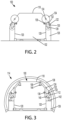
Figure 1 depicts a transformable cargo container. -
Figure 2 depicts a transformable cargo container in an aircraft configuration. -
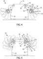
Figure 3 depicts a transformable cargo container in an aircraft configuration and stored in a fuselage of an aircraft. -
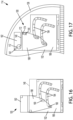
Figure 4 depicts a transformable cargo container in an intermediate position between an aircraft configuration a ground configuration. -
Figure 5 depicts a transformable cargo container in a ground configuration. -
Figure 6 depicts a transformable cargo container in a ground configuration and stored on a ground transportation vehicle. -
Figure 7 depicts a transformable cargo container in an aircraft configuration. -
Figure 8 depicts a transformable cargo container in an aircraft configuration and stored in a fuselage of an aircraft. -
Figure 9 depicts a transformable cargo container in an intermediate position between an aircraft configuration a ground configuration. -
Figure 10 depicts a transformable cargo container in another intermediate position between an aircraft configuration a ground configuration. -
Figure 11 depicts a transformable cargo container in another intermediate position between an aircraft configuration a ground configuration. -
Figure 12 depicts a transformable cargo container in another intermediate position between an aircraft configuration a ground configuration. -
Figure 13 depicts a transformable cargo container in another intermediate position between an aircraft configuration a ground configuration. -
Figure 14 depicts a transformable cargo container in a ground configuration. -
Figure 15 depicts a transformable cargo container in an aircraft configuration and stored in a fuselage of an aircraft with other cargo stacked thereon. -
Figure 16 depicts a transformable cargo container in an aircraft configuration. -
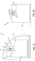
Figure 17 depicts a transformable cargo container in an aircraft configuration and stored in a fuselage of an aircraft. -
Figure 18 depicts a transformable cargo container in a ground configuration. -
Figure 19 depicts a transformable cargo container in an aircraft configuration and stored in a fuselage of an aircraft. -
Figure 20 depicts a transformable cargo container in a ground configuration. -
Figure 21 depicts a transformable cargo container in an aircraft configuration and stored in a fuselage of an aircraft with other cargo stacked thereon. -
Figure 22 depicts a perspective view of a transformable cargo container in an aircraft configuration. -
Figure 23 depicts a front view of a supply duct, plenum, and plenum lid when a transformable cargo container is in an aircraft configuration. -
Figure 24 depicts a perspective view of a transformable cargo container in a ground configuration. -
Figure 25 depicts a front view of a supply duct, plenum, and plenum lid when a transformable cargo container is in a ground configuration. -
Figure 26 depicts a transformable cargo container in an aircraft configuration and stored in a fuselage of an aircraft. -
Figure 27 depicts a perspective view of a transformable cargo container in a ground configuration. -
Figure 28 depicts a transformable cargo container in an aircraft configuration and stored in a fuselage of an aircraft. -
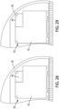
Figure 29 depicts a transformable cargo container in an aircraft configuration and stored in a fuselage of an aircraft. -
Figure 30 depicts a cargo container stored in a fuselage of an aircraft with other cargo secured thereon under a cargo net. -
Figure 31 depicts a cargo container stored in a fuselage of an aircraft with other cargo secured thereon under straps. -
Figure 32 shows a flowchart of a method. -
Figure 33 shows a flowchart of another method,. - Disclosed examples will now be described more fully hereinafter with reference to the accompanying drawings, in which some, but not all of the disclosed examples are shown. Indeed, several different examples may be described and should not be construed as limited to the examples set forth herein. Rather, these examples are described so that this disclosure will be thorough and complete and will fully convey the scope of the disclosure to those skilled in the art.
- Unless otherwise specifically noted, elements depicted in the drawings are not necessarily drawn to scale.
- Within examples, described herein are transformable cargo containers and a corresponding method for use with ground transportation vehicles and air transportation vehicles. The term "ground," as used herein, refers to transportation by road, rail, water, or other means of transportation other than air transportation. Thus, a ground transportation vehicle can take the form of a truck, train, cargo ship, or other vehicle configured to travel by ground or water, and a ground configuration of the disclosed transformable cargo container can be a configuration of the transformable cargo container that is suitable for storage of the transformable cargo container on such a ground transportation vehicle.
- Furthermore, the disclosed transformable cargo containers can take the form of refrigerated cargo containers or non-refrigerated cargo containers. That is, the examples disclosed herein, while primarily described and illustrated in the context of refrigerated cargo containers and maintaining refrigeration during intermodal transportation, can also be implemented in non-refrigeration scenarios. As described in more detail below, both the disclosed refrigerated cargo containers and disclosed non-refrigerated cargo containers (also referred to herein collectively as "transformable cargo containers") can have the same advantage of efficient transfer between ground and air transportation without having to unload stored goods from one cargo container and load those goods into a different cargo container. In addition, although temperature-related examples are primarily described herein as refrigerated examples, it should be understood that heating equipment could be used additionally or alternatively to refrigeration equipment, such as in situations where the stored cargo needs to be kept warm or hot during transportation.
- The disclosed transformable cargo container includes a main container body defining a storage chamber therein and including at least one inlet. The disclosed transformable cargo container also includes a transformable assembly coupled to the main container body and positioned at an exterior of the main container body. The transformable assembly is movable between an aircraft configuration and a ground configuration, and includes one or more supplemental containers and one or more supply ducts. At least one of the one or more supplemental containers is configured to house refrigeration equipment that is used to control the temperature inside the main container body.
- Based on the transformable assembly being in the aircraft configuration, the refrigeration equipment is configured to supply coolant (e.g., cool air, another gaseous coolant, and/or a liquid coolant) into the main container body via the one or more supply ducts and the at least one inlet. And within examples, based on the transformable assembly being in the aircraft configuration, the transformable cargo container also has a non-rectangular cross-sectional area and is configured to occupy a partially-circular cross-sectional storage area of a fuselage of an aircraft. Further, based on the transformable assembly being in the ground configuration, the refrigeration equipment is configured to supply coolant into the main container body via the one or more supply ducts and the at least one inlet. And within examples, based on the transformable assembly being in the ground configuration, the transformable cargo container is configured to occupy a rectangular cross-sectional storage area on a ground transportation vehicle.
- Accordingly, the transformable cargo container can be efficiently transferred between ground and air transportation by transitioning the transformable assembly between the ground and air configurations. In addition, refrigeration can be maintained in both configurations such that breaks in the cold chain are minimized and any temperature-sensitive products stored in the transformable cargo container do not need to be unloaded between ground and air legs of a journey.
- These and other improvements are described in more detail below. Implementations described below are for purposes of example. The implementations described below, as well as other implementations, may provide other improvements as well.
- Referring now to the figures,
Figure 1 depicts atransformable cargo container 100, according to an example implementation. The various elements of thetransformable cargo container 100 could be formed from one or more materials such as aluminum, steel, plastic, and/or another material. Furthermore, it will be understood that any of the elements shown inFigure 1 can include parts that are not explicitly shown inFigure 1 . - The
transformable cargo container 100 includes amain container body 102 and atransformable assembly 104. Themain container body 102 can define a storage chamber therein, in which various items can be stored, such as temperature-sensitive products. In examples where thetransformable cargo container 100 is a refrigerated cargo container, themain container body 102 includes at least oneinlet 106, whereas examples in which thetransformable cargo container 100 is a non-refrigerated cargo container, the at least oneinlet 106 might not be present. - The
transformable assembly 104 includes one or moresupplemental containers 108. In examples where thetransformable cargo container 100 is a refrigerated cargo container, thetransformable assembly 104 also includes one ormore supply ducts 110, and at least one of the one or moresupplemental containers 108 is configured to house (e.g., store)refrigeration equipment 112 that is configured to control a temperature inside themain container body 102. Whereas, examples in which thetransformable cargo container 100 is a non-refrigerated cargo container, the one ormore supply ducts 110 might not be present, and the one or moresupplemental containers 108 may or might not be configured to store additional items (e.g., additional goods that are being transported). For instance, in non-refrigerated examples, the one or moresupplemental containers 108 can be configured to house cargo instead of therefrigeration equipment 112, and the associated supply duct(s), inlet(s), etc. of the refrigerated examples might not be present. Within alternative examples, in non-refrigerated examples, if the one or moresupplemental containers 108 are designed to store therefrigeration equipment 112, the one or moresupplemental containers 108 can be interchangeably replaced with other supplemental containers that are specifically designed to store cargo. - The
refrigeration equipment 112 can take the form of a compressor (e.g., an internal combustion-powered compressor) or other temperature control device. In some examples, a gearing mechanism or other mechanism can be present in the one or moresupplemental containers 108 that is configured to suspend therefrigeration equipment 112 so that therefrigeration equipment 112 is oriented in the same way regardless of how the one or moresupplemental containers 108 are oriented during transition between the aircraft and ground configurations. - In some examples, a given one of the one or more
supplemental containers 108 stores therefrigeration equipment 112 as well as cargo. In such examples, therefrigeration equipment 112 might not take up the whole volume of that supplemental container, and thus therefrigeration equipment 112 can also control the temperature in a portion of that supplemental container that carries cargo. - Within examples, the one or
more supply ducts 110 includes a single supply duct operably connected to a particular inlet of the at least oneinlet 106 and configured to facilitate the supply of coolant into themain container body 102 in both the ground and aircraft configuration. Within other examples, the one ormore supply ducts 110 includes at least two supply ducts. Examples of each arrangement are described in more detail below. Further, within examples, the one ormore supply ducts 110 are located inside the main container body 102 (e.g., coupled to an interior surface within the main container body 102), outside the main container body 102 (e.g., coupled to an exterior surface of the main container body 102), and/or built into at least one sidewall of themain container body 102. - Within examples, the
transformable cargo container 100 includes one or more return ducts (not shown), which can be embedded in front and/or aft sidewalls of themain container body 102 or located elsewhere. Such return duct(s) can be configured to attach to the one or moresupplemental containers 108 in both the ground and aircraft configurations. In alternative examples, the one ormore supply ducts 110 also act as return ducts. - As described in more detail below, the
transformable assembly 104 is operably coupled to themain container body 102 and positioned at an exterior of themain container body 102. Thetransformable assembly 104 is also used to facilitate storage of thetransformable cargo container 100 in both aircraft and ground transportation vehicles, representative examples of which are depicted inFigure 1 asaircraft 114 andground transportation vehicle 116. - To facilitate this, the
transformable assembly 104 is movable between an aircraft configuration and a ground configuration, thereby effectively putting thetransformable cargo container 100 in the aircraft configuration and the ground configuration, respectively. Based on thetransformable assembly 104 being in the aircraft configuration, therefrigeration equipment 112 is configured to supply coolant into themain container body 102 via the one ormore supply ducts 110 and the at least oneinlet 106. And based on thetransformable assembly 104 being in the ground configuration, therefrigeration equipment 112 is configured to supply coolant into themain container body 102 via the one ormore supply ducts 110 and the at least oneinlet 106. - Additionally, in both refrigerated and non-refrigerated cargo container examples, the
transformable cargo container 100 has a non-rectangular cross-sectional area and is configured to occupy a partially-circular cross-sectional storage area of a fuselage of theaircraft 114 when thetransformable assembly 104 is in the aircraft configuration. And when thetransformable assembly 104 is in the ground configuration, thetransformable cargo container 100 is configured to occupy a rectangular cross-sectional storage area on a ground transportation vehicle 116 (e.g., on a truck bed). The size and shape of the one or moresupplemental containers 108 can be selected based on one or more dimensions (e.g., a width) of a partially-circular cross-sectional storage area of theaircraft 114 and/or of a rectangular cross-sectional storage area on theground transportation vehicle 116. In some situations, the dimensions of the rectangular cross-sectional storage area substantially conform to dimensions of a non-transformable intermodal container (e.g., 8 feet wide and 8 or 9.5 feet high). - The
aircraft 114 can take the form of various types of aircraft, such as commercial or non-commercial aircraft. Theground transportation vehicle 116 can take various forms as well, such as a truck, train, or cargo ship. - The
transformable assembly 104 can be operably coupled to themain container body 102 in various ways. For example, thetransformable assembly 104 can be rotatably coupled by way of a hinge, track, pivot pin, and/or other mechanism(s). Other examples are possible as well. -
Figures 2-15 next depict example of thetransformable cargo container 100 in which, based on thetransformable assembly 104 being in the aircraft configuration, the one or moresupplemental containers 108 are positioned at one or both lateral sidewalls of themain container body 102, and also, based on thetransformable assembly 104 being in the ground configuration, the one or moresupplemental containers 108 are positioned on top of themain container body 102. For reference, the top 118 andlateral sidewalls 120 of an example of themain container body 102 are indicated inFigure 2 . -
Figures 2-6 first depict an example of thetransformable cargo container 100 in which the one or moresupplemental containers 108 include afirst container 122 rotatably coupled to themain container body 102 via afirst hinge 124 and asecond container 126 rotatably coupled to thefirst container 122 via asecond hinge 128, abracket 130, and adrive mechanism 132. Thedrive mechanism 132 can be or include one or more gears, motors, socket wrenches, tools, controllers, or other mechanisms. - In addition, the
main container body 102 has chamfered corners. Although the arrangement ofFigures 2-6 is shown on both a left lateral sidewall and a right lateral sidewall of thelateral sidewalls 120 of themain container body 102, only the arrangement on the right is denoted for simplicity. - In this example, the
first hinge 124 is configured to couple to asprocket 134, and thetransformable assembly 104 also includes adrive gear 136 coupled to the main container body 102 (i.e., an exterior surface of themain container body 102, such as a longitudinal sidewall of the main container body 102) and configured to couple to thesprocket 134 and move thetransformable assembly 104 between the aircraft and ground configurations based on movement of thesprocket 134. As such, when it is time to move thetransformable assembly 104 between the aircraft and ground configurations, thesprocket 134 can be coupled to thefirst hinge 124 and thedrive gear 136 can be moved (i.e., rotated), such as using a human-operated hand crank or autonomous mechanism, thereby causing movement of thetransformable assembly 104 between the aircraft and ground configurations. In addition, thedrive mechanism 132 can be rotated as well in a similar manner to assist with moving thetransformable assembly 104 between the aircraft and ground configurations. -
Figure 2 depicts thetransformable cargo container 100 in the aircraft configuration, and with thesprocket 134 coupled to thefirst hinge 124. While the example ofFigure 2 is not a refrigerated example, therefrigeration equipment 112 can be included in thesecond container 126, as shown inFigures 3-5 . -
Figure 3 depicts a refrigerated example of thetransformable cargo container 100 that is in the aircraft configuration and stored in afuselage 138 of theaircraft 114. As shown, thefuselage 138 has a partially-circular cross-sectional storage area, with boundaries defined in part by the curved interior surface of thefuselage 138. - In
Figure 3 , the one ormore supply ducts 110 take the form of afirst supply duct 140 and asecond supply duct 142, each disposed at least partially within the one or more supplemental containers 108 - namely, within thesecond container 126. As shown, the at least oneinlet 106 takes the form of a duct disposed within the interior of themain container body 102, the duct having one inlet at the top 118 of themain container body 102 and another inlet at the right sidewall of thelateral sidewalls 120. - As so arranged, based on the
transformable assembly 104 being in the aircraft configuration shown inFigure 3 , therefrigeration equipment 112 is configured to supply coolant into themain container body 102 via thefirst supply duct 140 and the at least oneinlet 106. And based on thetransformable assembly 104 being in the ground configuration (as shown inFigure 5 ), therefrigeration equipment 112 is configured to supply coolant into themain container body 102 via thesecond supply duct 142 and the at least oneinlet 106. - Within examples, the
transformable cargo container 100 can also include at least onecoolant diffuser 144 coupled to the at least oneinlet 106 and positioned within themain container body 102. In alternative examples, other mechanisms for distributing coolant into themain container body 102 can be used instead of a coolant diffuser, such as a plurality of holes disposed in the one ormore supply ducts 110 or a plenum. - In the aircraft configuration shown in
Figure 3 , thefirst supply duct 140 connects to the at least oneinlet 106 at the right sidewall of thelateral sidewalls 120 and facilitates the supply of coolant into themain container body 102 via the at least onecoolant diffuser 144. - Example movement from the aircraft configuration to the ground configuration will now be described and illustrated with respect to
Figures 4 and 5 . - To facilitate movement from the aircraft configuration to the ground configuration, the teeth of the
sprocket 134 mesh with thedrive gear 136, and thedrive gear 136 is rotated manually by means of a socket wrench, by a socket drive connected to an electrical motor, or by another means. The center of thesprocket 134 is rigidly connected to a portion of thefirst container 122 such that as thesprocket 134 rotates, thefirst container 122 also rotates the same amount about thefirst hinge 124. Further, thebracket 130 rigidly couples thesecond container 126 to thefirst container 122 so that thesecond container 126 substantially follows the same rotational motion of thefirst container 122. In alternative arrangements, thefirst container 122 can take the form of a bracket connecting thedrive gear 136 to thesprocket 134. - The
sprocket 134 is first rotated approximately 15 degrees so that thefirst container 122 and thesecond container 126 also rotate 15 degrees together about thefirst hinge 124, so as to provide some clearance for a subsequent rotation about thefirst hinge 124 and so thesecond container 126 will not scrape up against the nearby sidewall of themain container body 102. Thedrive gear 136 is then locked at 15 degrees and thesecond container 126 is then rotated counterclockwise relative to thefirst container 122 via manual (e.g., a hand crank) or electric operation of thedrive mechanism 132. Although not explicitly shown, thedrive mechanism 132 can include one or more linked gears disposed at least partially within thefirst container 122, one of which is coupled to thesecond hinge 128. Thesecond container 126 is rotated approximately 90 degrees relative to thefirst container 122, at which point thesecond container 126 can be locked relative to thefirst container 122. -
Figure 4 depicts movement of thetransformable assembly 104 to an intermediate position between the aircraft configuration and the ground configuration - namely, the position in which thesecond container 126 is rotated approximately 90 degrees relative to thefirst container 122 as indicated above. - Once the
second container 126 is rotated approximately 90 degrees relative to thefirst container 122, thefirst container 122 and thesecond container 126 are together rotated about thefirst hinge 124 until thefirst container 122 contacts achamfered corner 146 of themain container body 102 and thesecond container 126 contacts the top 118 (i.e., a top/upper surface) of themain container body 102. At this point, thesecond supply duct 142 aligns with the at least oneinlet 106 so that therefrigeration equipment 112 can supply coolant into themain container body 102. -
Figure 5 depicts movement of thetransformable assembly 104 from the intermediate position ofFigure 4 to the ground configuration. In the ground configuration, thesecond supply duct 142 connects to the at least oneinlet 106 at the top 118 of themain container body 102 and facilitates the supply of coolant into themain container body 102 via the at least onecoolant diffuser 144. -
Figure 6 next depicts thetransformable assembly 104 in the ground configuration and a non-refrigerated version of thetransformable cargo container 100 stored on theground transportation vehicle 116, which takes the form of a truck bed. As shown, thetransformable cargo container 100 occupies a rectangularcross-sectional storage area 148 on theground transportation vehicle 116, which is designated inFigure 6 as a rectangular box with dashed lines. As further shown, within some examples,additional containers 150 can be stored on top of thetransformable cargo container 100 when thetransformable assembly 104 is in the ground configuration. - Additionally, indicated in
Figure 6 and shown in various other Figures herein arecorner fittings 152. Thecorner fittings 152 can be made of steel, carbon, or another material, and can be configured to (i) connect thetransformable cargo container 100 to another container, such as anothertransformable cargo container 100 or another type of cargo container (e.g., additional containers 150) and (ii) connect thetransformable cargo container 100 to a transport vehicle such as theaircraft 114 or theground transportation vehicle 116. Within examples, the one or moresupplemental containers 108 have thecorner fittings 152 as well. -
Figures 7-15 next depict an example of thetransformable cargo container 100 in which themain container body 102 comprises atrack 154 disposed on alongitudinal sidewall 156 of themain container body 102, and the one or moresupplemental containers 108 include afulcrum box 158. Thefulcrum box 158 is positioned at a lateral sidewall (e.g., the right lateral sidewall of the two lateral sidewalls 120) of themain container body 102 and is slidably and pivotably coupled to thetrack 154. Although the arrangement ofFigures 7-15 is shown on both the left lateral sidewall and the right lateral sidewall of thelateral sidewalls 120 of themain container body 102, only the arrangement on the right is denoted for simplicity. - When the
transformable cargo container 100 ofFigures 7-15 has been moved from the aircraft configuration to the ground configuration, thetransformable cargo container 100 occupies the rectangularcross-sectional storage area 148 on the ground transportation vehicle 116 (not shown). -
Figure 7 depicts thetransformable cargo container 100 in the aircraft configuration. While the example ofFigure 7 is not a refrigerated example, therefrigeration equipment 112 can be included in thefulcrum box 158, as shown inFigure 8-14 . The rectangularcross-sectional storage area 148 is designated inFigure 7 , for instance, which is not occupied inFigure 7 since thetransformable cargo container 100 is in the aircraft configuration, but will be occupied when in the ground configuration (e.g., inFigure 14 ). - The
fulcrum box 158 is slidably and pivotably coupled to thetrack 154 by way of abracket 160, as well as aroller pin 162 coupled to thebracket 160 and configured to slide within thetrack 154 and pivot thefulcrum box 158. Thebracket 160 is also coupled to aframe 164 that holds a plurality of rollers 166 (depicted as black dots) that facilitates linear movement of thefulcrum box 158 relative to theframe 164. Further, theframe 164 is coupled to a C-channel (not explicitly shown inFigure 7 , but shown inFigure 13 ), which is in turn coupled to (or integral with one panel of) a plurality of hingedpanels 168. The C-channel and the plurality of hingedpanels 168 couple thefulcrum box 158 to theframe 164. The plurality of hingedpanels 168 are configured to move the fulcrum box between a retracted position in which thefulcrum box 158 is retracted inward towards themain container body 102 and an extended position in which thefulcrum box 158 is extended outward away from themain container body 102. InFigure 7 , thefulcrum box 158 is in the extended position. - Based on the
fulcrum box 158 being in the extended position, thefulcrum box 158 is configured to move around atop corner 170 of themain container body 102. That is, the plurality of hingedpanels 168 are configured to help thefulcrum box 158 clear thetop corner 170 when thefulcrum box 158 is moved between the aircraft and ground configurations. As such, in alternative examples in which themain container body 102 has chamfered top corners, the plurality of hingedpanels 168 might not be included. -
Figure 8 depicts a refrigerated example of thetransformable cargo container 100 that is in the aircraft configuration and stored in thefuselage 138 of theaircraft 114. In addition, thefulcrum box 158 is in the retracted position. - In
Figure 8 , the one ormore supply ducts 110 take the form of thefirst supply duct 140 and thesecond supply duct 142, each disposed at least partially within thefulcrum box 158. As shown, a portion of thefirst supply duct 140 is disposed in an interior of thefulcrum box 158 and a remaining portion of thefirst supply duct 140 is disposed exterior to themain container body 102 and thefulcrum box 158. Further, an entirety of thesecond supply duct 142 is disposed in the interior of thefulcrum box 158. - Within examples, the one or
more supply ducts 110 are movable between an extended position outside of the one or moresupplemental containers 108 and a retracted position inside the one or moresupplemental containers 108. More specifically, in this particular example, thefirst supply duct 140 is retractable. InFigure 8 , thefirst supply duct 140 is shown in the extended position, where it connects therefrigeration equipment 112 to afirst inlet 172 and facilitates the supply of coolant into themain container body 102 via the at least onecoolant diffuser 144 when thetransformable cargo container 100 is in the aircraft configuration. In order to transition to the ground configuration, thefirst supply duct 140 is retracted to the retracted position, and once in the ground configuration, thesecond supply duct 142 connects therefrigeration equipment 112 to asecond inlet 174 and facilitates the supply of coolant into themain container body 102 via the at least onecoolant diffuser 144. - Example movement from the aircraft configuration to the ground configuration will now be described and illustrated with respect to
Figures 9-14 . The movement described with respect to this example can be accomplished manually or at least partially autonomously via a drive mechanism or combination of drive mechanisms. -
Figure 9 depicts thefirst supply duct 140 being retracted from the extended position towards the retracted position. Thefulcrum box 158 is in the retracted position as well. -
Figure 10 depicts thefirst supply duct 140 having been fully retracted. In addition, thefulcrum box 158 has been moved outward into the extended position. -
Figure 11 depicts thefulcrum box 158 having been raised to the end of thetrack 154, at which point thefulcrum box 158 is rotated about an axis defined by theroller pin 162. Because thefulcrum box 158 is in the extended position, it can clear thetop corner 170. -
Figure 12 depicts thefulcrum box 158 still in the extended position and having been moved laterally towards a center of thetransformable cargo container 100. -
Figure 13 depicts a cross-sectional view of thetransformable cargo container 100 taken along line A-A, but with the plurality of hingedpanels 168 being retracted so as to bring thefulcrum box 158 from the extended position to the retracted position. Also shown is a C-channel 176 to which the plurality of hingedpanels 168 are hingedly coupled and to which theframe 164 is coupled. -
Figure 14 depicts thetransformable cargo container 100 in the ground configuration. Thefulcrum box 158 is in the retracted position and thesecond supply duct 142 connects therefrigeration equipment 112 to thesecond inlet 174. Although not explicitly shown, thefulcrum box 158 can also be coupled (e.g., latched) to themain container body 102 to prevent movement of the fulcrum box 158 (e.g., until it is time to transition back to the aircraft configuration). In examples such as that shown inFigure 14 where there are two fulcrum boxes, the two boxes can be latched or otherwise coupled together on top of themain container body 102 so as to maintain thetransformable cargo container 100 in the ground configuration, by providing a load path that improves stiffness and strength of thetransformable cargo container 100 in the ground configuration. - Although the
track 154 is depicted inFigures 7-14 as a linear track that extends vertically towards a top of themain container body 102, in alternative examples thetrack 154 can include a horizontal portion proximate to the top of themain container body 102, so as to approximately form a right-angled track that facilitates movement of thefulcrum box 158 toward the position illustrated inFigures 12 and14 . In such an alternative example, thetrack 154 can eliminate the need for at least theframe 164 and the plurality ofrollers 166. - In some situations, based on the
transformable assembly 104 being in the ground configuration, another container (or multiple other containers) is/are stackable on top of thefulcrum box 158. An example of this is shown inFigure 15 . -
Figure 15 depicts a non-refrigerated example of thetransformable cargo container 100, as similarly shown inFigure 7 , in which based on thetransformable assembly 104 being in the ground configuration, a plurality ofother cargo 178 are stacked on thefulcrum box 158 and secured with acargo net 180. -
Figures 16-29 next depict example examples of thetransformable cargo container 100 in which the one or moresupplemental containers 108 are positioned on top of (or otherwise relative to the same exterior surface of) themain container body 102 in both the aircraft and ground configurations. That is, based on thetransformable assembly 104 being in the aircraft configuration, the one or moresupplemental containers 108 are positioned on top of themain container body 102, and also, based on thetransformable assembly 104 being in the ground configuration, the one or moresupplemental containers 108 are positioned on top of themain container body 102. - Moreover, the
main container body 102 depicted in each ofFigures 16-29 has a cross-sectional area that has a non-rectangular, stepped polygon shape, which can maximize the volume of thetransformable cargo container 100 while still fitting in thefuselage 138 of theaircraft 114. -
Figures 16-18 first depict an example of thetransformable cargo container 100 in which the one or moresupplemental containers 108 includes aswing box 182, themain container body 102 includes a plurality oftracks 184 disposed on alongitudinal sidewall 186 of themain container body 102, and thetransformable assembly 104 includes asupport structure 188 that is coupled to theswing box 182 and configured to move along the plurality oftracks 184. Although not explicitly shown, the other longitudinal sidewall of themain container body 102, opposite tolongitudinal sidewall 186, includes another plurality of tracks, similar to the plurality oftracks 184 shown inFigures 16-18 , and thesupport structure 188 is configured to move along that other plurality of tracks as well. - The
support structure 188 is supported at two locations by a plurality of pins 190 (or rollers) that fit inside the plurality oftracks 184. The load in theswing box 182 is transferred into thesupport structure 188, into the plurality ofpins 190, into the plurality oftracks 184, and then into the longitudinal sidewalls of themain container body 102. -
Figure 16 depicts thetransformable cargo container 100 in an intermediate position between the aircraft configuration and the ground configuration. Ten positions are labeled along the plurality oftracks 184, with position "1" corresponding to the aircraft configuration. Position "10" corresponds to the ground configuration, in which case thetransformable cargo container 100 occupies the rectangularcross-sectional storage area 148 on the ground transportation vehicle 116 (not shown).. As shown, thesupport structure 188 is at position "2". While the example ofFigure 16 is not a refrigerated example, therefrigeration equipment 112 can be included in theswing box 182, as shown inFigures 17-18 . -
Figure 17 depicts a refrigerated example of thetransformable cargo container 100 that is in the aircraft configuration and stored in thefuselage 138 of theaircraft 114. Thefirst supply duct 140 and thesecond supply duct 142 are each disposed within theswing box 182. Further, inFigure 17 , thefirst supply duct 140 connects therefrigeration equipment 112 to thefirst inlet 172 and facilitates the supply of coolant into themain container body 102 via the at least onecoolant diffuser 144 when thetransformable cargo container 100 is in the aircraft configuration. -
Figure 18 depicts the refrigerated example of thetransformable cargo container 100 that is in the ground configuration. In the ground configuration, thesecond supply duct 142 connects therefrigeration equipment 112 to thesecond inlet 174 and facilitates the supply of coolant into themain container body 102 via the at least onecoolant diffuser 144. - As an example advantage of the
swing box 182 example, the "up" direction for therefrigeration equipment 112 and/or cargo in theswing box 182 remains up for the complete duration of the trip between the aircraft and ground configurations, which is particular advantageous when transporting orientation-sensitive cargo such as flowers or fragile products. -
Figures 19-21 next depict an example refrigerated example of thetransformable cargo container 100 in which the one or moresupplemental containers 108 includes ahinge box 192 rotatably coupled to the top of themain container body 102 via ahinge 194. -
Figure 19 depicts thetransformable cargo container 100 in the aircraft configuration and stored in thefuselage 138 of theaircraft 114. Thefirst supply duct 140 and thesecond supply duct 142 are each disposed within thehinge box 192. Further, with thetransformable cargo container 100 in the aircraft configuration, thefirst supply duct 140 connects therefrigeration equipment 112 to thefirst inlet 172 and facilitates the supply of coolant into themain container body 102 via the at least onecoolant diffuser 144. -
Figure 20 depicts thetransformable cargo container 100 in the ground configuration, after thehinge box 192 has rotated clockwise about thehinge 194. With thetransformable cargo container 100 in the ground configuration, thesecond supply duct 142 connects therefrigeration equipment 112 to thesecond inlet 174 and facilitates the supply of coolant into themain container body 102 via the at least onecoolant diffuser 144. In some scenarios, other containers can be stacked on thetransformable cargo container 100 when thetransformable cargo container 100 is in the ground configuration. -
Figure 21 depicts thetransformable cargo container 100 in the aircraft configuration and stored in thefuselage 138. Within examples, and as shown, based on thetransformable assembly 104 being in the aircraft configuration, the plurality ofother cargo 178 are stacked on themain container body 102 and secured with thecargo net 180. -
Figures 22-29 next depict example examples of thetransformable cargo container 100 in which themain container body 102 includes plurality of tracks 196 (e.g., slide rails) disposed at least on the top 118 of themain container body 102, and the one or moresupplemental containers 108 include aslide box 198 configured to move laterally along the plurality oftracks 196. As in other examples of the one or moresupplemental containers 108 described herein, dimensions (e.g., a width) of theslide box 198 are selected based on a width of a partially-circular cross-sectional storage area of thefuselage 138 of theaircraft 114. - In refrigerated examples such as those shown in
Figures 22-27 , the one ormore supply ducts 110 take the form of a supply duct 200 (i.e., a single supply duct) that facilitates the constant supply of coolant into themain container body 102 in both the aircraft and ground configurations, as well as during the entire transition between the aircraft and ground configurations. This can be accomplished using a sliding plenum and/or a flexible supply duct.Figures 22-25 relate to the former, andFigures 26-27 relate to the latter.Figures 28-29 then depict a non-refrigerated example of thetransformable cargo container 100 having theslide box 198. -
Figure 22 depicts a perspective view of thetransformable cargo container 100 in the aircraft configuration in which theslide box 198 abuts a right sidewall of atop portion 208 of themain container body 102. As shown, in addition to the plurality oftracks 196, twosupplemental tracks 202 are included as well to facilitate lateral movement of theslide box 198. In this example, themain container body 102 includes aplenum 204 that is inside themain container body 102 and underneath theslide box 198. Further, thetransformable assembly 104 also includes a slidingplenum lid 206 coupled between theplenum 204 and thesupply duct 200. The slidingplenum lid 206 covers all openings between themain container body 102 and theplenum 204, thus helping to ensure a sealed system. Although not explicitly shown, theplenum 204 can include the at least one inlet 106 (i.e., a single inlet, in this case) through which coolant is supplied into the interior of themain container body 102. -
Figure 23 depicts a front view of thesupply duct 200, theplenum 204, and theplenum lid 206 when thetransformable cargo container 100 is in the aircraft configuration. -
Figure 24 depicts a perspective view of thetransformable cargo container 100 in the ground configuration. - Based on the
transformable assembly 104 being in the ground configuration, another container (not shown inFigure 24 , but shown inFigure 27 ) is storable on top of themain container body 102 and between theslide box 198 and thetop portion 208 of themain container body 102. In particular, as shown, there is an empty space to the left of theslide box 198, which in some cases can be filled in with additional cargo containers selected based on the dimensions of the space and the dimensions of theslide box 198. -
Figure 25 depicts a front view of thesupply duct 200, theplenum 204, and theplenum lid 206 when thetransformable cargo container 100 is in the ground configuration. -
Figures 26-27 depicts an example of thetransformable cargo container 100 where thesupply duct 200 is a flexible duct that connects therefrigeration equipment 112 to the at least one inlet 106 (i.e., a single inlet, in this case) in both the aircraft and ground configurations. To prevent coolant from escaping, the at least oneinlet 106 and thesupply duct 200 can be coupled by way of a rubber seal or other sealant between theslide box 198 and themain container body 102. -
Figure 26 first depicts thetransformable cargo container 100 in the aircraft configuration and stored in thefuselage 138 of theaircraft 114. -
Figure 27 then depicts thetransformable cargo container 100 in the ground configuration and with anadditional container 210 stacked on themain container body 102 between theslide box 198 and thetop portion 208 of themain container body 102. -
Figure 28 and Figure 29 each depict a non-refrigerated example of thetransformable cargo container 100 that is in the aircraft configuration and stored in thefuselage 138 of theaircraft 114. Theslide box 198 inFigure 28 has a smaller dimension than theslide box 198 inFigure 29 . - Depending on the dimensions of the storage area of the
fuselage 138 of theaircraft 114, the design of thetransformable cargo container 100 and one or more components thereof (e.g., the slide box 198) can be adjusted so that theslide box 198 has adequate clearance between theslide box 198 and the interior wall of the storage area, while maximizing cargo volume. Depending on the make and model of theaircraft 114, this width dimension can vary. -
Figure 30 depicts an example of themain container body 102 that is stored in thefuselage 138 of theaircraft 114. As shown, themain container body 102 has a substantially flat top surface and the plurality ofother cargo 178 are stacked on themain container body 102 and secured with thecargo net 180. Thecargo net 180 is attached to the top edges of themain container body 102 by way of clasps, D-rings, and/or other latching mechanisms. -
Figure 31 depicts an example of themain container body 102 that is stored in thefuselage 138 of theaircraft 114. As shown, themain container body 102 has a substantially flat top surface and the plurality ofother cargo 178 are stacked on themain container body 102 and secured with astrap 212 by way of clasps, D-rings, and/or other latching mechanisms. Within examples, thestrap 212 is one of a plurality of straps that are used to secure the plurality ofother cargo 178. Shrink wrap can be used additionally or alternatively to straps. - The configurations of
Figures 30-31 enable the convenient placement of loose cargo on the top of themain container body 102, which can be convenient for cargo operators in filling any remaining storage space between themain container body 102 and thefuselage 138. After the cargo container reaches a destination airport, the plurality ofother cargo 178 can be unloaded. -
Figure 32 shows a flowchart of an example of amethod 300.Method 300 could be used with thetransformable cargo container 100 and components thereof shown inFigures 1-31 .Method 300 may include one or more operations, functions, or actions as illustrated by one or more of blocks 302-304. - At
block 302, themethod 300 includes moving a transformable assembly of a transformable cargo container from a ground configuration to an aircraft configuration, wherein the transformable assembly is coupled to a main container body of the transformable cargo container and comprises one or more supplemental containers, at least one of the one or more supplemental containers being configured to house refrigeration equipment, wherein the refrigeration equipment is configured to control a temperature inside the main container body, and wherein based on the transformable assembly being in the aircraft configuration, the refrigeration equipment is configured to supply coolant into the main container body. - At
block 304, themethod 300 includes loading the transformable cargo container into a fuselage of an aircraft based on the transformable assembly being in the aircraft configuration. - In some examples, based on the transformable assembly being in the aircraft configuration, the transformable cargo container has a non-rectangular cross-sectional area, and the loading of
block 304 involves loading the transformable cargo container into a partially-circular cross-sectional storage area of the fuselage of the aircraft based on the transformable assembly being in the aircraft configuration. - In some examples, the moving of
block 302 involves moving the one or more supplemental containers from a first position at one or both lateral sidewalls of the main container body to a second position on top of the main container body. - In some examples, the moving of
block 302 involves moving the one or more supplemental containers from a first position on top of the main container body to a second position on top of the main container body, different from the first position. - In some examples, the
method 300 also includes unloading the transformable cargo container from the fuselage of the aircraft based on the transformable assembly being in the aircraft configuration, and moving the transformable assembly from the aircraft configuration to the ground configuration. Within examples of such examples, the transformable assembly includes one or more supply ducts that are movable between an extended position outside of the one or more supplemental containers and a retracted position inside the one or more supplemental containers, and themethod 300 also includes, before moving the transformable assembly from the aircraft configuration to the ground configuration, moving the one or more supply ducts from the extended position to the retracted position. Within other examples of such examples, themethod 300 also includes loading the transformable cargo container directly (e.g., without unloading any cargo, such as temperature-sensitive products, and while maintaining refrigeration of the cargo) from the aircraft and onto a ground transportation vehicle. -
Figure 33 shows a flowchart of an example of amethod 400.Method 400 could be used with thetransformable cargo container 100 and components thereof shown inFigures 1-31 .Method 400 may include one or more operations, functions, or actions as illustrated by one or more of blocks 402-404. - At
block 402, themethod 400 includes moving a transformable assembly of a transformable cargo container from a ground configuration to an aircraft configuration, the transformable cargo container comprising a main container body defining a storage chamber therein, wherein the transformable assembly is coupled to the main container body and positioned at an exterior of the main container body, wherein the transformable assembly comprises one or more supplemental containers, and wherein based on the transformable assembly being in the aircraft configuration, the transformable cargo container has a non-rectangular cross-sectional area. - At
block 404, themethod 400 includes loading the transformable cargo container into a partially-circular cross-sectional storage area of a fuselage of an aircraft based on the transformable assembly being in the aircraft configuration. - In some examples, the moving of
block 402 involves moving the one or more supplemental containers from a first position at one or both lateral sidewalls of the main container body to a second position on top of the main container body. - In some examples, the moving of
block 402 involves moving the one or more supplemental containers from a first position on top of the main container body to a second position on top of the main container body, different from the first position. - In some examples, the
method 400 also includes unloading the transformable cargo container from the fuselage of the aircraft based on the transformable assembly being in the aircraft configuration, and moving the transformable assembly from the aircraft configuration to the ground configuration. Within examples of such examples, themethod 400 also includes loading the transformable cargo container directly from the aircraft and onto a ground transportation vehicle, and stacking one or more other containers on the transformable cargo container based on the transformable assembly being in the ground configuration. - Different examples of the system(s), device(s), and method(s) disclosed herein include a variety of components, features, and functionalities. It should be understood that the various examples of the system(s), device(s), and method(s) disclosed herein may include any of the components, features, and functionalities of any of the other examples of the system(s), device(s), and method(s) disclosed herein in any combination or any sub-combination, and all of such possibilities are intended to be within the scope of the disclosure.
- The description of the different advantageous arrangements has been presented for purposes of illustration and description, and is not intended to be exhaustive or limited to the examples in the form disclosed. Many modifications and variations will be apparent to those of ordinary skill in the art. Further, different advantageous examples may describe different advantages as compared to other advantageous examples. The example or examples selected are chosen and described in order to best explain the principles of the examples, the practical application, and to enable others of ordinary skill in the art to understand the disclosure for various examples with various modifications as are suited to the particular use contemplated.
-
Clause 1. Disclosed is a transformable cargo container for use with ground and air transportation vehicles, the transformable cargo container comprising: a main container body defining a storage chamber therein and comprising at least one inlet; and a transformable assembly coupled to the main container body and positioned at an exterior of the main container body, wherein: the transformable assembly comprises one or more supplemental containers and one or more supply ducts, at least one of the one or more supplemental containers being configured to house refrigeration equipment, the refrigeration equipment is configured to control a temperature inside the main container body, the transformable assembly is movable between an aircraft configuration and a ground configuration, based on the transformable assembly being in the aircraft configuration, the refrigeration equipment is configured to supply coolant into the main container body via the one or more supply ducts and the at least one inlet, and based on the transformable assembly being in the ground configuration, the refrigeration equipment is configured to supply coolant into the main container body via the one or more supply ducts and the at least one inlet. -
Clause 2. The transformable cargo container ofClause 1, further comprising: at least one coolant diffuser coupled to the at least one inlet and positioned within the main container body. -
Clause 3. The transformable cargo container ofClauses -
Clause 4. The transformable cargo container of any of Clauses 1-3, wherein: the one or more supply ducts comprise a first supply duct and a second supply duct, each disposed at least partially within the one or more supplemental containers, based on the transformable assembly being in the aircraft configuration, the refrigeration equipment is configured to supply coolant into the main container body via the first supply duct and the at least one inlet, and based on the transformable assembly being in the ground configuration, the refrigeration equipment is configured to supply coolant into the main container body via the second supply duct and the at least one inlet. - Clause 5. The transformable cargo container of any of Clauses 1-4, wherein: based on the transformable assembly being in the aircraft configuration, the one or more supplemental containers are positioned at one or both lateral sidewalls of the main container body, and based on the transformable assembly being in the ground configuration, the one or more supplemental containers are positioned on top of the main container body.
- Clause 6. The transformable cargo container of any of Clauses 1-5, wherein: the one or more supplemental containers comprises: a first container rotatably coupled to the main container body via a first hinge, and a second container rotatably coupled to the first container via a second hinge and a bracket.
- Clause 7. The transformable cargo container of Clause 6, wherein: the first hinge is configured to couple to a sprocket, and the transformable assembly further comprises a drive gear coupled to the main container body and configured to couple to the sprocket and move the transformable assembly between the aircraft configuration and the ground configuration based on movement of the sprocket.
- Clause 8. The transformable cargo container of any of Clauses 1-5, wherein: the main container body comprises a track disposed on a longitudinal sidewall of the main container body, and the one or more supplemental containers comprises a fulcrum box positioned at a lateral sidewall of the main container body and slidably and pivotably coupled to the track.
- Clause 9. The transformable cargo container of Clause 8, wherein: the fulcrum box comprises a plurality of hinged panels configured to move the fulcrum box between a retracted position in which the fulcrum box is retracted inward towards the main container body and an extended positon in which the fulcrum box is extended outward away from the main container body, and based on the fulcrum box being in the extended position, the fulcrum box is configured to move around a top corner of the main container body.
-
Clause 10. The transformable cargo container of any of Clauses 1-4, wherein: based on the transformable assembly being in the aircraft configuration, the one or more supplemental containers are positioned on top of the main container body, and based on the transformable assembly being in the ground configuration, the one or more supplemental containers are positioned on top of the main container body. - Clause 11. The transformable cargo container of any of Clauses 1-4, wherein: the main container body comprises a plurality of tracks, the one or more supplemental containers comprises a swing box, the transformable assembly further comprises a support structure coupled to the swing box, and the support structure is configured to move along the plurality of tracks.
- Clause 12. The transformable cargo container of any of Clauses 1-4, wherein: the one or more supplemental containers comprises a hinge box rotatably coupled to a top of the main container body via a hinge.
- Clause 13. The transformable cargo container of any of Clauses 1-4, wherein: the main container body comprises a plurality of tracks disposed on a top of the main container body, and the one or more supplemental containers comprises a slide box configured to move laterally along the plurality of tracks.
- Clause 14. The transformable cargo container of Clause 13, wherein a width of the slide box is selected based on a width of a partially-circular cross-sectional storage area of a fuselage of an aircraft.
- Clause 15. The transformable cargo container of any of Clauses 1-14, wherein: based on the transformable assembly being in the aircraft configuration, the transformable cargo container has a non-rectangular cross-sectional area and is configured to occupy a partially-circular cross-sectional storage area of a fuselage of an aircraft, and based on the transformable assembly being in the ground configuration, the transformable cargo container is configured to occupy a rectangular cross-sectional storage area on a ground transportation vehicle.
- Clause 16. Disclosed is a method comprising: moving a transformable assembly of a transformable cargo container from a ground configuration to an aircraft configuration, wherein the transformable assembly is coupled to a main container body of the transformable cargo container and comprises one or more supplemental containers, at least one of the one or more supplemental containers being configured to house refrigeration equipment, wherein the refrigeration equipment is configured to control a temperature inside the main container body, and wherein based on the transformable assembly being in the aircraft configuration, the refrigeration equipment is configured to supply coolant into the main container body; and loading the transformable cargo container into a fuselage of an aircraft based on the transformable assembly being in the aircraft configuration.
- Clause 17. The method of Clause 16, wherein: based on the transformable assembly being in the aircraft configuration, the transformable cargo container has a non-rectangular cross-sectional area, and loading the transformable cargo container into the fuselage of the aircraft based on the transformable assembly being in the aircraft configuration comprises loading the transformable cargo container into a partially-circular cross-sectional storage area of the fuselage of the aircraft based on the transformable assembly being in the aircraft configuration.
- Clause 18. The method of Clause 16 or 17, wherein: moving the transformable assembly from the ground configuration to the aircraft configuration comprises moving the one or more supplemental containers from a first position at one or both lateral sidewalls of the main container body to a second position on top of the main container body.
- Clause 19. The method of Clause 16 or 17, wherein: moving the transformable assembly from the ground configuration to the aircraft configuration comprises moving the one or more supplemental containers from a first position on top of the main container body to a second position on top of the main container body, different from the first position.
-
Clause 20. The method of any of Clauses 16-19, further comprising: unloading the transformable cargo container from the fuselage of the aircraft based on the transformable assembly being in the aircraft configuration; and moving the transformable assembly from the aircraft configuration to the ground configuration. - Clause 21. The method of any of Clauses 16-20, wherein: the transformable assembly further comprises one or more supply ducts that are movable between an extended position outside of the one or more supplemental containers and a retracted position inside the one or more supplemental containers, and the method further comprises: before moving the transformable assembly from the aircraft configuration to the ground configuration, moving the one or more supply ducts from the extended position to the retracted position.
-
Clause 22. The method of any of Clauses 16-20, further comprising: loading the transformable cargo container directly from the aircraft and onto a ground transportation vehicle. - Clause 23. Disclosed is a transformable cargo container for use with ground and air transportation vehicles, the transformable cargo container comprising: a main container body defining a storage chamber therein and comprising at least one inlet; and a transformable assembly coupled to the main container body and positioned at an exterior of the main container body, wherein: the transformable assembly comprises one or more supplemental containers and one or more supply ducts, at least one of the one or more supplemental containers being configured to house refrigeration equipment, the refrigeration equipment is configured to control a temperature inside the main container body, the transformable assembly is movable between an aircraft configuration and a ground configuration, based on the transformable assembly being in the aircraft configuration, (i) the one or more supplemental containers are positioned on top of the main container body in a first position and (ii) the refrigeration equipment is configured to supply coolant into the main container body via the one or more supply ducts and the at least one inlet, and based on the transformable assembly being in the ground configuration, (i) the one or more supplemental containers are positioned on top of the main container body in a second position on top of the main container body, different from the first position, and (ii) the refrigeration equipment is configured to supply coolant into the main container body via the one or more supply ducts and the at least one inlet.
Claims (15)
- A transformable cargo container (100) for use with ground and air transportation vehicles, the transformable cargo container (100) comprising:a main container body (102) defining a storage chamber therein and comprising at least one inlet (106); anda transformable assembly (104) coupled to the main container body (102) and positioned at an exterior of the main container body (102), wherein:the transformable assembly (104) comprises one or more supplemental containers (108) and one or more supply ducts (110), at least one of the one or more supplemental containers (108) being configured to house refrigeration equipment (112),the refrigeration equipment (112) is configured to control a temperature inside the main container body (102),the transformable assembly (104) is movable between an aircraft configuration and a ground configuration,based on the transformable assembly (104) being in the aircraft configuration, the refrigeration equipment (112) is configured to supply coolant into the main container body (102) via the one or more supply ducts (110) and the at least one inlet (106), andbased on the transformable assembly (104) being in the ground configuration, the refrigeration equipment (112) is configured to supply coolant into the main container body (102) via the one or more supply ducts (110) and the at least one inlet (106).
- The transformable cargo container (100) of claim 1, further comprising:
at least one coolant diffuser (144) coupled to the at least one inlet (106) and positioned within the main container body (102). - The transformable cargo container (100) of claim 1 or 2, wherein:
the one or more supply ducts (110) are movable between an extended position outside of the one or more supplemental containers (108) and a retracted position inside the one or more supplemental containers (108). - The transformable cargo container (100) of any of claims 1-3, wherein:the one or more supply ducts (110) comprise a supply duct (200) first supply duct (200) (140) and a supply duct (200)second supply duct (200) (142), each disposed at least partially within the one or more supplemental containers (108),based on the transformable assembly (104) being in the aircraft configuration, the refrigeration equipment (112) is configured to supply coolant into the main container body (102) via the supply duct (200)first supply duct (200) (140) and the at least one inlet (106), andbased on the transformable assembly (104) being in the ground configuration, the refrigeration equipment (112) is configured to supply coolant into the main container body (102) via the supply duct (200)second supply duct (200) (142) and the at least one inlet (106).
- The transformable cargo container (100) of any of claims 1-4, wherein:based on the transformable assembly (104) being in the aircraft configuration, the one or more supplemental containers (108) are positioned at one or both lateral sidewalls (120) of the main container body (102), andbased on the transformable assembly (104) being in the ground configuration, the one or more supplemental containers (108) are positioned on top (118) of the main container body (102).
- The transformable cargo container (100) of any of claims 1-5, wherein:
the one or more supplemental containers (108) comprises:a first container (122) rotatably coupled to the main container body (102) via a first hinge (124), anda second container (126) rotatably coupled to the first container (122) via a second hinge (128) and a bracket (130). - The transformable cargo container (100) of claim 6, wherein:the first hinge (124) is configured to couple to a sprocket (134), andthe transformable assembly (104) further comprises a drive gear (136) coupled to the main container body (102) and configured to couple to the sprocket (134) and move the transformable assembly (104) between the aircraft configuration and the ground configuration based on movement of the sprocket (134).
- The transformable cargo container (100) of any of claims 1-5, wherein:the main container body (102) comprises a track (154) disposed on a longitudinal sidewall (156) of the main container body (102), andthe one or more supplemental containers (108) comprises a fulcrum box (158) positioned at a lateral sidewall of the main container body (102) and slidably and pivotably coupled to the track (154).
- The transformable cargo container (100) of claim 8, wherein:the fulcrum box (158) comprises a plurality of hinged panels (168) configured to move the fulcrum box (158) between a retracted position in which the fulcrum box (158) is retracted inward towards the main container body (102) and an extended positon in which the fulcrum box (158) is extended outward away from the main container body (102), andbased on the fulcrum box (158) being in the extended position, the fulcrum box (158) is configured to move around a top (118) corner of the main container body (102).
- The transformable cargo container (100) of any of claims 1-4, wherein:based on the transformable assembly (104) being in the aircraft configuration, the one or more supplemental containers (108) are positioned on top (118) of the main container body (102), andbased on the transformable assembly (104) being in the ground configuration, the one or more supplemental containers (108) are positioned on top (118) of the main container body (102).
- The transformable cargo container (100) of any of claims 1-4, wherein:the main container body (102) comprises a plurality of tracks (184),the one or more supplemental containers (108) comprises a swing box (182),the transformable assembly (104) further comprises a support structure (188) coupled to the swing box (182), andthe support structure (188) is configured to move along the plurality of tracks (184).
- The transformable cargo container (100) of any of claims 1-4, wherein:
the one or more supplemental containers (108) comprises a hinge box (192) rotatably coupled to a top (118) of the main container body (102) via a hinge (194). - The transformable cargo container (100) of any of claims 1-4, wherein:the main container body (102) comprises a plurality of tracks (196) disposed on a top (118) of the main container body (102), andthe one or more supplemental containers (108) comprises a slide box (198) configured to move laterally along the plurality of tracks (196).
- The transformable cargo container (100) of claim 13, wherein a width of the slide box (198) is selected based on a width of a partially-circular cross-sectional storage area of a fuselage (138) of an aircraft (114).
- The transformable cargo container (100) of any of claims 1-14, wherein:based on the transformable assembly (104) being in the aircraft configuration, the transformable cargo container (100) has a non-rectangular cross-sectional area and is configured to occupy a partially-circular cross-sectional storage area of a fuselage (138) of an aircraft (114), andbased on the transformable assembly (104) being in the ground configuration, the transformable cargo container (100) is configured to occupy a rectangular cross-sectional storage area (148) on a ground transportation vehicle (116).
Applications Claiming Priority (1)
| Application Number | Priority Date | Filing Date | Title |
|---|---|---|---|
| US17/580,072 US11939150B2 (en) | 2022-01-20 | 2022-01-20 | Transformable refrigerated cargo containers |
Publications (2)
| Publication Number | Publication Date |
|---|---|
| EP4215851A1 true EP4215851A1 (en) | 2023-07-26 |
| EP4215851B1 EP4215851B1 (en) | 2024-08-07 |
Family
ID=85017772
Family Applications (1)
| Application Number | Title | Priority Date | Filing Date |
|---|---|---|---|
| EP23152539.5A Active EP4215851B1 (en) | 2022-01-20 | 2023-01-19 | Transformable refrigerated cargo containers |
Country Status (4)
| Country | Link |
|---|---|
| US (1) | US11939150B2 (en) |
| EP (1) | EP4215851B1 (en) |
| CN (1) | CN116461865A (en) |
| CA (1) | CA3187335A1 (en) |
Families Citing this family (1)
| Publication number | Priority date | Publication date | Assignee | Title |
|---|---|---|---|---|
| US12570463B2 (en) * | 2022-11-17 | 2026-03-10 | Thermo King Llc | Method and system for monitoring weight/orientation of a self-contained climate controlled storage unit and adjusting operation based on the monitored weight/orientation |
Citations (2)
| Publication number | Priority date | Publication date | Assignee | Title |
|---|---|---|---|---|
| WO2007130770A2 (en) * | 2006-05-02 | 2007-11-15 | Satco, Inc. | Air cargo container extension unit |
| US20090184126A1 (en) * | 2007-12-28 | 2009-07-23 | Airbus Deutschland Gmbh | Airfreight container and aircraft |
Family Cites Families (5)
| Publication number | Priority date | Publication date | Assignee | Title |
|---|---|---|---|---|
| US5125237A (en) * | 1987-11-12 | 1992-06-30 | Louis P. Saia, III | Portable self-contained cooler/freezer apparatus for use on airplanes, common carrier type unrefrigerated truck lines, and the like |
| US6813898B2 (en) * | 1999-07-21 | 2004-11-09 | Leslie John Lindsay | Refrigerated air freight container |
| US7913511B2 (en) * | 2005-06-08 | 2011-03-29 | Doubleday Acquisitions, Llc | Cargo container for transporting temperature sensitive items |
| US20190195547A1 (en) * | 2017-12-27 | 2019-06-27 | William G. Moon | Modular and separable cryogenic shipping system |
| CN112577227A (en) * | 2019-09-27 | 2021-03-30 | 开利公司 | Container equipment and article storage and transportation method |
-
2022
- 2022-01-20 US US17/580,072 patent/US11939150B2/en active Active
-
2023
- 2023-01-19 EP EP23152539.5A patent/EP4215851B1/en active Active
- 2023-01-19 CN CN202310078166.4A patent/CN116461865A/en active Pending
- 2023-01-20 CA CA3187335A patent/CA3187335A1/en active Pending
Patent Citations (2)
| Publication number | Priority date | Publication date | Assignee | Title |
|---|---|---|---|---|
| WO2007130770A2 (en) * | 2006-05-02 | 2007-11-15 | Satco, Inc. | Air cargo container extension unit |
| US20090184126A1 (en) * | 2007-12-28 | 2009-07-23 | Airbus Deutschland Gmbh | Airfreight container and aircraft |
Also Published As
| Publication number | Publication date |
|---|---|
| EP4215851B1 (en) | 2024-08-07 |
| US11939150B2 (en) | 2024-03-26 |
| CA3187335A1 (en) | 2023-07-20 |
| CN116461865A (en) | 2023-07-21 |
| US20230227250A1 (en) | 2023-07-20 |
Similar Documents
| Publication | Publication Date | Title |
|---|---|---|
| CA3187213A1 (en) | Transformable cargo containers | |
| US12319494B2 (en) | Container structure and associated assembly, method and adjustment mechanism | |
| US10457503B2 (en) | Apparatus and method for intermodal distribution of freight | |
| EP4215851B1 (en) | Transformable refrigerated cargo containers | |
| JP3336429B2 (en) | Air freight transportation system | |
| CN111572612A (en) | Handling device is transported in commodity circulation | |
| US20200062281A1 (en) | Multimodal Platform for Railcar | |
| US20210122590A1 (en) | System, apparatus, and method for freight redistribution | |
| US6247740B1 (en) | Wall divider system for use in trucks | |
| US12084266B2 (en) | Transformable cargo containers | |
| CN216231896U (en) | A refrigerated truck for easy unloading | |
| US20120181268A1 (en) | Refrigerated freight container | |
| CN219948000U (en) | Box structure and freight train convenient to goods loading and unloading | |
| CN214523508U (en) | AGV commodity circulation delivery car | |
| CN117508917B (en) | Multifunctional container for food, fruits and vegetables | |
| CN112407070A (en) | Agricultural product cold-chain logistics conveying and transferring equipment and method | |
| CN118372728A (en) | A layered loading and unloading cargo box for a logistics transport vehicle and a method of using the same | |
| US12312158B2 (en) | Refrigerator box and method of using same | |
| CN220485205U (en) | Lifting structure for loading and unloading freight carriage | |
| KR200396854Y1 (en) | Container for joining or separating from vehicles | |
| JPH09254704A (en) | Inner partition device of loading box for motor-truck | |
| CN224240898U (en) | Unmanned express delivery case transfer car (buggy) | |
| CN221418117U (en) | Vehicle-mounted accessory box and transport vehicle | |
| CN221137897U (en) | Side pulling carriage with follow-up pulling platform | |
| CN222538720U (en) | Carrying device and vehicle |
Legal Events
| Date | Code | Title | Description |
|---|---|---|---|
| PUAI | Public reference made under article 153(3) epc to a published international application that has entered the european phase |
Free format text: ORIGINAL CODE: 0009012 |
|
| STAA | Information on the status of an ep patent application or granted ep patent |
Free format text: STATUS: THE APPLICATION HAS BEEN PUBLISHED |
|
| AK | Designated contracting states |
Kind code of ref document: A1 Designated state(s): AL AT BE BG CH CY CZ DE DK EE ES FI FR GB GR HR HU IE IS IT LI LT LU LV MC ME MK MT NL NO PL PT RO RS SE SI SK SM TR |
|
| STAA | Information on the status of an ep patent application or granted ep patent |
Free format text: STATUS: REQUEST FOR EXAMINATION WAS MADE |
|
| 17P | Request for examination filed |
Effective date: 20240109 |
|
| RBV | Designated contracting states (corrected) |
Designated state(s): AL AT BE BG CH CY CZ DE DK EE ES FI FR GB GR HR HU IE IS IT LI LT LU LV MC ME MK MT NL NO PL PT RO RS SE SI SK SM TR |
|
| GRAP | Despatch of communication of intention to grant a patent |
Free format text: ORIGINAL CODE: EPIDOSNIGR1 |
|
| STAA | Information on the status of an ep patent application or granted ep patent |
Free format text: STATUS: GRANT OF PATENT IS INTENDED |
|
| RIC1 | Information provided on ipc code assigned before grant |
Ipc: B64D 9/00 20060101ALI20240501BHEP Ipc: B60J 1/00 20060101ALI20240501BHEP Ipc: B65D 88/14 20060101ALI20240501BHEP Ipc: F25D 19/00 20060101ALI20240501BHEP Ipc: F25D 17/08 20060101ALI20240501BHEP Ipc: F25D 11/00 20060101AFI20240501BHEP |
|
| INTG | Intention to grant announced |
Effective date: 20240522 |
|
| GRAS | Grant fee paid |
Free format text: ORIGINAL CODE: EPIDOSNIGR3 |
|
| GRAA | (expected) grant |
Free format text: ORIGINAL CODE: 0009210 |
|
| STAA | Information on the status of an ep patent application or granted ep patent |
Free format text: STATUS: THE PATENT HAS BEEN GRANTED |
|
| AK | Designated contracting states |
Kind code of ref document: B1 Designated state(s): AL AT BE BG CH CY CZ DE DK EE ES FI FR GB GR HR HU IE IS IT LI LT LU LV MC ME MK MT NL NO PL PT RO RS SE SI SK SM TR |
|
| P01 | Opt-out of the competence of the unified patent court (upc) registered |
Free format text: CASE NUMBER: APP_39494/2024 Effective date: 20240702 |
|
| REG | Reference to a national code |
Ref country code: GB Ref legal event code: FG4D |
|
| REG | Reference to a national code |
Ref country code: CH Ref legal event code: EP |
|
| REG | Reference to a national code |
Ref country code: IE Ref legal event code: FG4D |
|
| REG | Reference to a national code |
Ref country code: DE Ref legal event code: R096 Ref document number: 602023000321 Country of ref document: DE |
|
| REG | Reference to a national code |
Ref country code: LT Ref legal event code: MG9D |
|
| REG | Reference to a national code |
Ref country code: NL Ref legal event code: MP Effective date: 20240807 |
|
| PG25 | Lapsed in a contracting state [announced via postgrant information from national office to epo] |
Ref country code: NO Free format text: LAPSE BECAUSE OF FAILURE TO SUBMIT A TRANSLATION OF THE DESCRIPTION OR TO PAY THE FEE WITHIN THE PRESCRIBED TIME-LIMIT Effective date: 20241107 |
|
| REG | Reference to a national code |
Ref country code: AT Ref legal event code: MK05 Ref document number: 1711360 Country of ref document: AT Kind code of ref document: T Effective date: 20240807 |
|
| PG25 | Lapsed in a contracting state [announced via postgrant information from national office to epo] |
Ref country code: PT Free format text: LAPSE BECAUSE OF FAILURE TO SUBMIT A TRANSLATION OF THE DESCRIPTION OR TO PAY THE FEE WITHIN THE PRESCRIBED TIME-LIMIT Effective date: 20241209 Ref country code: GR Free format text: LAPSE BECAUSE OF FAILURE TO SUBMIT A TRANSLATION OF THE DESCRIPTION OR TO PAY THE FEE WITHIN THE PRESCRIBED TIME-LIMIT Effective date: 20241108 Ref country code: PL Free format text: LAPSE BECAUSE OF FAILURE TO SUBMIT A TRANSLATION OF THE DESCRIPTION OR TO PAY THE FEE WITHIN THE PRESCRIBED TIME-LIMIT Effective date: 20240807 Ref country code: NL Free format text: LAPSE BECAUSE OF FAILURE TO SUBMIT A TRANSLATION OF THE DESCRIPTION OR TO PAY THE FEE WITHIN THE PRESCRIBED TIME-LIMIT Effective date: 20240807 Ref country code: FI Free format text: LAPSE BECAUSE OF FAILURE TO SUBMIT A TRANSLATION OF THE DESCRIPTION OR TO PAY THE FEE WITHIN THE PRESCRIBED TIME-LIMIT Effective date: 20240807 |
|
| PG25 | Lapsed in a contracting state [announced via postgrant information from national office to epo] |
Ref country code: BG Free format text: LAPSE BECAUSE OF FAILURE TO SUBMIT A TRANSLATION OF THE DESCRIPTION OR TO PAY THE FEE WITHIN THE PRESCRIBED TIME-LIMIT Effective date: 20240807 |
|
| PG25 | Lapsed in a contracting state [announced via postgrant information from national office to epo] |
Ref country code: LV Free format text: LAPSE BECAUSE OF FAILURE TO SUBMIT A TRANSLATION OF THE DESCRIPTION OR TO PAY THE FEE WITHIN THE PRESCRIBED TIME-LIMIT Effective date: 20240807 |
|
| PG25 | Lapsed in a contracting state [announced via postgrant information from national office to epo] |
Ref country code: IS Free format text: LAPSE BECAUSE OF FAILURE TO SUBMIT A TRANSLATION OF THE DESCRIPTION OR TO PAY THE FEE WITHIN THE PRESCRIBED TIME-LIMIT Effective date: 20241207 Ref country code: AT Free format text: LAPSE BECAUSE OF FAILURE TO SUBMIT A TRANSLATION OF THE DESCRIPTION OR TO PAY THE FEE WITHIN THE PRESCRIBED TIME-LIMIT Effective date: 20240807 |
|
| PG25 | Lapsed in a contracting state [announced via postgrant information from national office to epo] |
Ref country code: HR Free format text: LAPSE BECAUSE OF FAILURE TO SUBMIT A TRANSLATION OF THE DESCRIPTION OR TO PAY THE FEE WITHIN THE PRESCRIBED TIME-LIMIT Effective date: 20240807 |
|
| PG25 | Lapsed in a contracting state [announced via postgrant information from national office to epo] |
Ref country code: RS Free format text: LAPSE BECAUSE OF FAILURE TO SUBMIT A TRANSLATION OF THE DESCRIPTION OR TO PAY THE FEE WITHIN THE PRESCRIBED TIME-LIMIT Effective date: 20241107 Ref country code: ES Free format text: LAPSE BECAUSE OF FAILURE TO SUBMIT A TRANSLATION OF THE DESCRIPTION OR TO PAY THE FEE WITHIN THE PRESCRIBED TIME-LIMIT Effective date: 20240807 |
|
| PG25 | Lapsed in a contracting state [announced via postgrant information from national office to epo] |
Ref country code: RS Free format text: LAPSE BECAUSE OF FAILURE TO SUBMIT A TRANSLATION OF THE DESCRIPTION OR TO PAY THE FEE WITHIN THE PRESCRIBED TIME-LIMIT Effective date: 20241107 Ref country code: PT Free format text: LAPSE BECAUSE OF FAILURE TO SUBMIT A TRANSLATION OF THE DESCRIPTION OR TO PAY THE FEE WITHIN THE PRESCRIBED TIME-LIMIT Effective date: 20241209 Ref country code: PL Free format text: LAPSE BECAUSE OF FAILURE TO SUBMIT A TRANSLATION OF THE DESCRIPTION OR TO PAY THE FEE WITHIN THE PRESCRIBED TIME-LIMIT Effective date: 20240807 Ref country code: NO Free format text: LAPSE BECAUSE OF FAILURE TO SUBMIT A TRANSLATION OF THE DESCRIPTION OR TO PAY THE FEE WITHIN THE PRESCRIBED TIME-LIMIT Effective date: 20241107 Ref country code: NL Free format text: LAPSE BECAUSE OF FAILURE TO SUBMIT A TRANSLATION OF THE DESCRIPTION OR TO PAY THE FEE WITHIN THE PRESCRIBED TIME-LIMIT Effective date: 20240807 Ref country code: LV Free format text: LAPSE BECAUSE OF FAILURE TO SUBMIT A TRANSLATION OF THE DESCRIPTION OR TO PAY THE FEE WITHIN THE PRESCRIBED TIME-LIMIT Effective date: 20240807 Ref country code: IS Free format text: LAPSE BECAUSE OF FAILURE TO SUBMIT A TRANSLATION OF THE DESCRIPTION OR TO PAY THE FEE WITHIN THE PRESCRIBED TIME-LIMIT Effective date: 20241207 Ref country code: HR Free format text: LAPSE BECAUSE OF FAILURE TO SUBMIT A TRANSLATION OF THE DESCRIPTION OR TO PAY THE FEE WITHIN THE PRESCRIBED TIME-LIMIT Effective date: 20240807 Ref country code: GR Free format text: LAPSE BECAUSE OF FAILURE TO SUBMIT A TRANSLATION OF THE DESCRIPTION OR TO PAY THE FEE WITHIN THE PRESCRIBED TIME-LIMIT Effective date: 20241108 Ref country code: FI Free format text: LAPSE BECAUSE OF FAILURE TO SUBMIT A TRANSLATION OF THE DESCRIPTION OR TO PAY THE FEE WITHIN THE PRESCRIBED TIME-LIMIT Effective date: 20240807 Ref country code: ES Free format text: LAPSE BECAUSE OF FAILURE TO SUBMIT A TRANSLATION OF THE DESCRIPTION OR TO PAY THE FEE WITHIN THE PRESCRIBED TIME-LIMIT Effective date: 20240807 Ref country code: BG Free format text: LAPSE BECAUSE OF FAILURE TO SUBMIT A TRANSLATION OF THE DESCRIPTION OR TO PAY THE FEE WITHIN THE PRESCRIBED TIME-LIMIT Effective date: 20240807 Ref country code: AT Free format text: LAPSE BECAUSE OF FAILURE TO SUBMIT A TRANSLATION OF THE DESCRIPTION OR TO PAY THE FEE WITHIN THE PRESCRIBED TIME-LIMIT Effective date: 20240807 |
|
| PG25 | Lapsed in a contracting state [announced via postgrant information from national office to epo] |
Ref country code: SM Free format text: LAPSE BECAUSE OF FAILURE TO SUBMIT A TRANSLATION OF THE DESCRIPTION OR TO PAY THE FEE WITHIN THE PRESCRIBED TIME-LIMIT Effective date: 20240807 Ref country code: DK Free format text: LAPSE BECAUSE OF FAILURE TO SUBMIT A TRANSLATION OF THE DESCRIPTION OR TO PAY THE FEE WITHIN THE PRESCRIBED TIME-LIMIT Effective date: 20240807 |
|
| PG25 | Lapsed in a contracting state [announced via postgrant information from national office to epo] |
Ref country code: EE Free format text: LAPSE BECAUSE OF FAILURE TO SUBMIT A TRANSLATION OF THE DESCRIPTION OR TO PAY THE FEE WITHIN THE PRESCRIBED TIME-LIMIT Effective date: 20240807 |
|
| PG25 | Lapsed in a contracting state [announced via postgrant information from national office to epo] |
Ref country code: CZ Free format text: LAPSE BECAUSE OF FAILURE TO SUBMIT A TRANSLATION OF THE DESCRIPTION OR TO PAY THE FEE WITHIN THE PRESCRIBED TIME-LIMIT Effective date: 20240807 |
|
| PG25 | Lapsed in a contracting state [announced via postgrant information from national office to epo] |
Ref country code: SK Free format text: LAPSE BECAUSE OF FAILURE TO SUBMIT A TRANSLATION OF THE DESCRIPTION OR TO PAY THE FEE WITHIN THE PRESCRIBED TIME-LIMIT Effective date: 20240807 |
|
| REG | Reference to a national code |
Ref country code: DE Ref legal event code: R097 Ref document number: 602023000321 Country of ref document: DE |
|
| PLBE | No opposition filed within time limit |
Free format text: ORIGINAL CODE: 0009261 |
|
| STAA | Information on the status of an ep patent application or granted ep patent |
Free format text: STATUS: NO OPPOSITION FILED WITHIN TIME LIMIT |
|
| 26N | No opposition filed |
Effective date: 20250508 |
|
| PG25 | Lapsed in a contracting state [announced via postgrant information from national office to epo] |
Ref country code: SE Free format text: LAPSE BECAUSE OF FAILURE TO SUBMIT A TRANSLATION OF THE DESCRIPTION OR TO PAY THE FEE WITHIN THE PRESCRIBED TIME-LIMIT Effective date: 20240807 |
|
| PG25 | Lapsed in a contracting state [announced via postgrant information from national office to epo] |
Ref country code: LU Free format text: LAPSE BECAUSE OF NON-PAYMENT OF DUE FEES Effective date: 20250119 Ref country code: MC Free format text: LAPSE BECAUSE OF FAILURE TO SUBMIT A TRANSLATION OF THE DESCRIPTION OR TO PAY THE FEE WITHIN THE PRESCRIBED TIME-LIMIT Effective date: 20240807 |
|
| PG25 | Lapsed in a contracting state [announced via postgrant information from national office to epo] |
Ref country code: BE Free format text: LAPSE BECAUSE OF NON-PAYMENT OF DUE FEES Effective date: 20250131 |
|
| REG | Reference to a national code |
Ref country code: BE Ref legal event code: MM Effective date: 20250131 |
|
| PG25 | Lapsed in a contracting state [announced via postgrant information from national office to epo] |
Ref country code: IE Free format text: LAPSE BECAUSE OF NON-PAYMENT OF DUE FEES Effective date: 20250119 |
|
| PG25 | Lapsed in a contracting state [announced via postgrant information from national office to epo] |
Ref country code: IT Free format text: LAPSE BECAUSE OF FAILURE TO SUBMIT A TRANSLATION OF THE DESCRIPTION OR TO PAY THE FEE WITHIN THE PRESCRIBED TIME-LIMIT Effective date: 20240807 |
|
| PGFP | Annual fee paid to national office [announced via postgrant information from national office to epo] |
Ref country code: DE Payment date: 20260128 Year of fee payment: 4 |
|
| PG25 | Lapsed in a contracting state [announced via postgrant information from national office to epo] |
Ref country code: RO Free format text: LAPSE BECAUSE OF FAILURE TO SUBMIT A TRANSLATION OF THE DESCRIPTION OR TO PAY THE FEE WITHIN THE PRESCRIBED TIME-LIMIT Effective date: 20240807 |
|
| PGFP | Annual fee paid to national office [announced via postgrant information from national office to epo] |
Ref country code: FR Payment date: 20260126 Year of fee payment: 4 |