EP4215823A1 - An expansion apparatus - Google Patents
An expansion apparatus Download PDFInfo
- Publication number
- EP4215823A1 EP4215823A1 EP23152192.3A EP23152192A EP4215823A1 EP 4215823 A1 EP4215823 A1 EP 4215823A1 EP 23152192 A EP23152192 A EP 23152192A EP 4215823 A1 EP4215823 A1 EP 4215823A1
- Authority
- EP
- European Patent Office
- Prior art keywords
- fluid
- membrane
- expansion apparatus
- expansion
- closed
- Prior art date
- Legal status (The legal status is an assumption and is not a legal conclusion. Google has not performed a legal analysis and makes no representation as to the accuracy of the status listed.)
- Granted
Links
Images


Classifications
-
- F—MECHANICAL ENGINEERING; LIGHTING; HEATING; WEAPONS; BLASTING
- F24—HEATING; RANGES; VENTILATING
- F24D—DOMESTIC- OR SPACE-HEATING SYSTEMS, e.g. CENTRAL HEATING SYSTEMS; DOMESTIC HOT-WATER SUPPLY SYSTEMS; ELEMENTS OR COMPONENTS THEREFOR
- F24D3/00—Hot-water central heating systems
- F24D3/10—Feed-line arrangements, e.g. providing for heat-accumulator tanks, expansion tanks ; Hydraulic components of a central heating system
- F24D3/1008—Feed-line arrangements, e.g. providing for heat-accumulator tanks, expansion tanks ; Hydraulic components of a central heating system expansion tanks
- F24D3/1016—Tanks having a bladder
Definitions
- the present invention relates to an expansion apparatus that prevents the increase of the closed-circuit installation pressure by balancing the expansion of the heated fluid in the installations through which a heated fluid is flowing.
- the invention discloses an expansion apparatus comprising at least one fluid inlet and a flexible membrane in which the fluid is filled through this fluid inlet and is directly subject to atmospheric pressure.
- Open expansion vessels are the oldest technique that is used for this purpose. As the technology evolved, this technique was replaced by closed expansion tanks.
- Current closed expansion tanks comprise a metal surface, expandable membrane, and an air section that paddings this membrane. Air section is the volume between metal surface and membrane.
- Water on the system expands after heating and thus its volume increases.
- the expanded water enters the expansion tank and system pressure is reduced. In the meantime, it compresses the air inside the expansion tank.
- water in the installation cools down, water volume and pressure decrease.
- compressed air inside the tank sends the water inside the system back to installation and adjust system pressure to a fixed level.
- Expansion valves that currently used contain a metal container with expandable membrane and a padding air section thus they are both heavy and has big volumes. Also, due to the metal surface, they have a fixed structure. For this reason, it does not have flexibility and cannot be produced in geometries that cannot be made with a deep drawing die.
- an expansion tank which is equipped with an elastic diagram that divides it into an air chamber and a water chamber in the middle. Furthermore, air pressure inside the air chamber is measured by a sensor, and air is supplied with the compressor instead of the missing air.
- the aim of the present invention is to prevent increase in closed-circuit fluid installation pressure by balancing the expansion of heated fluid in the installations through which a heated fluid pass.
- Another aim of the invention is to provide an expansion apparatus that performs the function of elements such as pipes that transport water in a closed circuit and does not require additional maintenance.
- Another aim of the invention is to provide a sheath embodiment that acts as a stoper against the pressure in the membrane, and that prevents excessive swelling and damage of the membrane.
- present invention is an expansion apparatus for reducing pressure increase in closed-circuit fluid systems that comprises at least one fluid inlet, and a membrane in flexible form directly subject to atmospheric pressure, in which the fluid is filled by means of the fluid inlet.
- the mentioned membrane is made of elastomer material.
- the expansion apparatus further comprises a sheath structured to cover the membrane and whose volume can change in proportion to the pressure change to which the membrane is subjected.
- the sheath is made of air-permeable material.
- the expansion apparatus of the present invention comprises at least one fluid outlet in connection with the membrane allowing the expansion apparatus to be mounted in series to the closed-circuit fluid system and allowing the fluid in said membrane to be discharged from the expansion apparatus.
- the present invention discloses an expansion apparatus (1) based on pressure expansion principle.
- the expansion apparatus (1) comprises at least one fluid inlet (3), and a membrane (2) in flexible form directly subject to atmospheric pressure, in which the fluid is filled by means of the fluid inlet (3).
- the membrane (2) is made of elastomer class material inside of which is fiber supported or not supported.
- expansion apparatus has a fluid outlet (5) in an addition to the fluid inlet (3). With this fluid outlet (5), it is possible to connect the expansion apparatus in series (1) to the closed-circuit fluid system. In this embodiment, only difference from the expansion apparatus (1) without fluid outlet (5) is that fluid inside the membrane (2) will flow out from the fluid outlet (5) to another system. In both situations, as the fluid inside the closed circuit expands, it will blow the membrane (2) up, and pressure rise within the system will be prevented.
- expansion apparatus (1) also fulfills the function of a fluid transfer member like pipe. By this way, it is possible to save more space in units that need to be compact like boilers. Besides, it provides a volume advantage since the difficult shapes that need to be given to pipes can be given to the expansion apparatus (2).
- This sheath (4) is configured to in a way to cover the membrane (2), and its volume is able to change in proportion to the pressure change to which the membrane (2) is subjected.
- Sheath (4) serves as a second layer for the purpose of blocking physical contact of foreign materials like dust with membrane (2).
- the sheath (4) has a structure that is stretched in the bulky state of the membrane (2) and crumpled when it is deflated.
- the cover (4) has a certain strength that will both protect the membrane (2) from foreign substances and prevent it from further swelling with pressure.
- the material of the sheath (4) is selected from a material that is air-permeable, which will not prevent the membrane (2) from being directly subjected to atmospheric pressure.
- expansion apparatus (1) comprises
- atmospheric air is the padding for the expansion apparatus (1), it is not necessary to have closed space for the expansion.
- expansion apparatus (1) saves volume in boilers and tanks. Also, there is no demand for necessities like filling of padding air, supplying air in case of leakage, and comprising a relief valve connection.
Landscapes
- Engineering & Computer Science (AREA)
- Physics & Mathematics (AREA)
- Thermal Sciences (AREA)
- Chemical & Material Sciences (AREA)
- Combustion & Propulsion (AREA)
- Mechanical Engineering (AREA)
- General Engineering & Computer Science (AREA)
- Pipe Accessories (AREA)
- Separation Using Semi-Permeable Membranes (AREA)
Abstract
Description
- The present invention relates to an expansion apparatus that prevents the increase of the closed-circuit installation pressure by balancing the expansion of the heated fluid in the installations through which a heated fluid is flowing. In particular, the invention discloses an expansion apparatus comprising at least one fluid inlet and a flexible membrane in which the fluid is filled through this fluid inlet and is directly subject to atmospheric pressure.
- It is known that a fluid on closed systems expands when heated. As fluid expands it effects the pressure on closed systems by increasing its internal pressure. This increased pressure has the potential to harm the system. Expansion tanks are needed to relieve pressure and possible damage.
- Open expansion vessels are the oldest technique that is used for this purpose. As the technology evolved, this technique was replaced by closed expansion tanks. Current closed expansion tanks comprise a metal surface, expandable membrane, and an air section that paddings this membrane. Air section is the volume between metal surface and membrane.
- Water on the system expands after heating and thus its volume increases. The expanded water enters the expansion tank and system pressure is reduced. In the meantime, it compresses the air inside the expansion tank. As water in the installation cools down, water volume and pressure decrease. As water volume decreases, compressed air inside the tank sends the water inside the system back to installation and adjust system pressure to a fixed level.
- Expansion valves that currently used contain a metal container with expandable membrane and a padding air section thus they are both heavy and has big volumes. Also, due to the metal surface, they have a fixed structure. For this reason, it does not have flexibility and cannot be produced in geometries that cannot be made with a deep drawing die.
- These disadvantages caused necessity for a new expansion apparatus.
- In the utility model No.
CN20829320 , an expansion tank which is equipped with an elastic diagram that divides it into an air chamber and a water chamber in the middle. Furthermore, air pressure inside the air chamber is measured by a sensor, and air is supplied with the compressor instead of the missing air. - In the patent No.
CN102864818A , an expansion tank with an expandable membrane and an extra air section padding disclosed. - However, both aforementioned documents give no solution that our invention gives about metal body that creates weight and volume disadvantage to boiler and central heating boilers. Consequently, it was necessary to come up with a suitable solution that performs the same function but does not contain the existing disadvantages, instead of the expansion tanks used in units such as combi boilers or boilers.
- The aim of the present invention is to prevent increase in closed-circuit fluid installation pressure by balancing the expansion of heated fluid in the installations through which a heated fluid pass.
- Another aim of the present invention is to obtain an expansion apparatus that takes up less space in units such as boilers and combi boilers, is light in terms of the material used, and has a small volume.
- Another aim of the invention is to provide an expansion apparatus that performs the function of elements such as pipes that transport water in a closed circuit and does not require additional maintenance.
- Another aim of the invention is to provide a sheath embodiment that acts as a stoper against the pressure in the membrane, and that prevents excessive swelling and damage of the membrane.
- To achieve the above objectives, present invention is an expansion apparatus for reducing pressure increase in closed-circuit fluid systems that comprises at least one fluid inlet, and a membrane in flexible form directly subject to atmospheric pressure, in which the fluid is filled by means of the fluid inlet.
- In the preferred embodiment of the invention, the mentioned membrane is made of elastomer material.
- The expansion apparatus further comprises a sheath structured to cover the membrane and whose volume can change in proportion to the pressure change to which the membrane is subjected. The sheath is made of air-permeable material.
- In another preferred embodiment of the expansion apparatus of the present invention comprises at least one fluid outlet in connection with the membrane allowing the expansion apparatus to be mounted in series to the closed-circuit fluid system and allowing the fluid in said membrane to be discharged from the expansion apparatus.
- In
Figure 1a ; section view of the empty expansion apparatus in preferred embodiment is shown. - In
Figure 1b ; section view of the expansion apparatus while filled with fluid in preferred embodiment is shown. - In
Figure 2a ; section view of the empty expansion apparatus in another preferred embodiment is shown. - In
Figure 2b ; section view of the filled expansion apparatus in another preferred embodiment is shown. - In
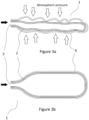
Figure 3a ; section view of the empty expansion apparatus comprising sheath in preferred embodiment is shown. - In
Figure 3b ; section view of the expansion apparatus comprising sheath while filled with fluid in preferred embodiment is shown. - In
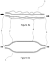
Figure 4a ; section view of the empty expansion apparatus comprising sheath in another preferred embodiment is shown. - In
Figure 4b ; section view of the filled expansion apparatus comprising sheath in another preferred embodiment is shown. -
- 1
- Expansion apparatus
- 2
- Membrane
- 3
- Fluid inlet
- 4
- Sheath
- 5
- Fluid outlet
- The present invention discloses an expansion apparatus (1) based on pressure expansion principle. According to the
Figure 1a , the expansion apparatus (1) comprises at least one fluid inlet (3), and a membrane (2) in flexible form directly subject to atmospheric pressure, in which the fluid is filled by means of the fluid inlet (3). The membrane (2) is made of elastomer class material inside of which is fiber supported or not supported. - With amount of the fluid that enters through fluid inlet (3) increases because of pressure in the fluid system, membrane will be filled with more water, and it will swell like a balloon as shown in the
Figure 1b . In this case of sudden pressure rise on the closed-circuit thus increasing water volume, water will be filled to another area i.e., to expansion apparatus (1) without harming the fluid system. - Embodiment that shown in
Figure 1a and 1b , in closed-circuit fluid systems, for example like heating systems or boilers, combis that work on these systems, fulfils the purpose of a closed expansion tank. - In
Figure 2a and 2b , another preferred embodiment of the expansion apparatus in empty and filled form is shown respectively. According to theFigure 2a , expansion apparatus has a fluid outlet (5) in an addition to the fluid inlet (3). With this fluid outlet (5), it is possible to connect the expansion apparatus in series (1) to the closed-circuit fluid system. In this embodiment, only difference from the expansion apparatus (1) without fluid outlet (5) is that fluid inside the membrane (2) will flow out from the fluid outlet (5) to another system. In both situations, as the fluid inside the closed circuit expands, it will blow the membrane (2) up, and pressure rise within the system will be prevented. - In the embodiment shown in
Figure 2b , expansion apparatus (1) also fulfills the function of a fluid transfer member like pipe. By this way, it is possible to save more space in units that need to be compact like boilers. Besides, it provides a volume advantage since the difficult shapes that need to be given to pipes can be given to the expansion apparatus (2). - In
Figure 3a and 3b , section view of another preferred embodiment of expansion apparatus (1) is shown schematically. The expansion apparatus (1) of the preferred embodiment comprises a membrane in flexible form (2), a fluid inlet (3) in which fluid enters from closed-circuit fluid system, a sheath (4) that protects the membrane (2) from foreign unwanted substances particles such as dust. - This sheath (4) is configured to in a way to cover the membrane (2), and its volume is able to change in proportion to the pressure change to which the membrane (2) is subjected. Sheath (4) serves as a second layer for the purpose of blocking physical contact of foreign materials like dust with membrane (2). The sheath (4) has a structure that is stretched in the bulky state of the membrane (2) and crumpled when it is deflated. In addition, the cover (4) has a certain strength that will both protect the membrane (2) from foreign substances and prevent it from further swelling with pressure. The material of the sheath (4) is selected from a material that is air-permeable, which will not prevent the membrane (2) from being directly subjected to atmospheric pressure.
- In another embodiment shown in
Figures 4a and 4b , expansion apparatus (1) comprises - at least one fluid inlet (3),
- a membrane (2) in flexible form directly subject to atmospheric pressure, in which the fluid is filled by means of the fluid inlet (3),
- at least one fluid outlet (5) in connection with the membrane (2), and
- a sheath (4) that is configured to in a way to cover the membrane (2).
- As it can be understood from
Figures 1 to 4 , an air gap unconnected with outside and isolated is not available in between membrane (2) and sheath (4), by which are constituted expansion apparatus (1). The membrane (2) is expected to have at least 2-4 mm of thickness, and sheath (4) is envisaged to have at least 1 mm thickness. The thickness values of membrane (2) and sheath (4) depend on the type of the material and amount of internal pressure inside the fluid system that expansion apparatus (1) to be connected to. - At the preferred embodiments of the present invention, atmospheric air is the padding for the expansion apparatus (1), it is not necessary to have closed space for the expansion. This way expansion apparatus (1) saves volume in boilers and tanks. Also, there is no demand for necessities like filling of padding air, supplying air in case of leakage, and comprising a relief valve connection.
Claims (5)
- An expansion apparatus (1) for reducing pressure increase in closed-circuit fluid systems characterized by comprising- at least one fluid inlet (3), and- a membrane (2) in flexible form directly subject to atmospheric pressure, in which the fluid is filled by means of the fluid inlet (3).
- The expansion apparatus (1) according to claim 1 wherein the membrane (2) is made of elastomer material.
- The expansion apparatus (1) according to claim 1 or 2, wherein it comprises a sheath (4) structured to cover the membrane (2) and whose volume is able to change in proportion to the pressure change to which the membrane (2) is subjected.
- The expansion apparatus (1) according to claim 3 wherein the sheath (4) is made of air-permeable material.
- The expansion apparatus (1) according to any one of claims 1 to 4, wherein it comprises at least one fluid outlet (5) in connection with the membrane (2) allowing the expansion apparatus (1) to be mounted in series to the closed-circuit fluid system and allowing the fluid in said membrane (2) to be discharged from the expansion apparatus (1).
Applications Claiming Priority (1)
| Application Number | Priority Date | Filing Date | Title |
|---|---|---|---|
| TR202200696 | 2022-01-20 |
Publications (2)
| Publication Number | Publication Date |
|---|---|
| EP4215823A1 true EP4215823A1 (en) | 2023-07-26 |
| EP4215823B1 EP4215823B1 (en) | 2025-10-01 |
Family
ID=84982202
Family Applications (1)
| Application Number | Title | Priority Date | Filing Date |
|---|---|---|---|
| EP23152192.3A Active EP4215823B1 (en) | 2022-01-20 | 2023-01-18 | An expansion apparatus |
Country Status (1)
| Country | Link |
|---|---|
| EP (1) | EP4215823B1 (en) |
Citations (6)
| Publication number | Priority date | Publication date | Assignee | Title |
|---|---|---|---|---|
| GB1460103A (en) * | 1973-05-16 | 1976-12-31 | Flamco Bv | Method of absorbing the changes in volume of a liquid medium in a central heating system and apparatus for carrying out the method |
| GB2188412A (en) * | 1986-02-11 | 1987-09-30 | Pressure Units Limited | Central heating system |
| WO2002039007A1 (en) * | 2000-11-08 | 2002-05-16 | Watts Investment Company | In-line thermal expansion tank |
| CN102691850A (en) * | 2012-05-30 | 2012-09-26 | 张秀英 | Volume regulator for closed fluid circulation loop |
| CN102864818A (en) | 2012-10-13 | 2013-01-09 | 温岭市联华机械有限公司 | Expansion tank |
| CN208293200U (en) | 2018-01-03 | 2018-12-28 | 东莞润信弹性织物有限公司 | A stretched and deformed mesh webbing |
-
2023
- 2023-01-18 EP EP23152192.3A patent/EP4215823B1/en active Active
Patent Citations (6)
| Publication number | Priority date | Publication date | Assignee | Title |
|---|---|---|---|---|
| GB1460103A (en) * | 1973-05-16 | 1976-12-31 | Flamco Bv | Method of absorbing the changes in volume of a liquid medium in a central heating system and apparatus for carrying out the method |
| GB2188412A (en) * | 1986-02-11 | 1987-09-30 | Pressure Units Limited | Central heating system |
| WO2002039007A1 (en) * | 2000-11-08 | 2002-05-16 | Watts Investment Company | In-line thermal expansion tank |
| CN102691850A (en) * | 2012-05-30 | 2012-09-26 | 张秀英 | Volume regulator for closed fluid circulation loop |
| CN102864818A (en) | 2012-10-13 | 2013-01-09 | 温岭市联华机械有限公司 | Expansion tank |
| CN208293200U (en) | 2018-01-03 | 2018-12-28 | 东莞润信弹性织物有限公司 | A stretched and deformed mesh webbing |
Also Published As
| Publication number | Publication date |
|---|---|
| EP4215823B1 (en) | 2025-10-01 |
Similar Documents
| Publication | Publication Date | Title |
|---|---|---|
| US3933172A (en) | Pipeline surge reliever with sanitary barrier | |
| US8633825B2 (en) | Expansion tank with a predictive sensor | |
| CN112411683B (en) | Diaphragm expansion tank for water network pressure compensation | |
| WO2006082765A1 (en) | Seal structure of high-pressure tank | |
| JP2010500248A (en) | Expansion tank with predictive sensor | |
| CN118961137B (en) | Water tunnel experimental device | |
| EP4215823B1 (en) | An expansion apparatus | |
| US5391209A (en) | Method for controlling overpressurization in a gas line | |
| JP2007537538A (en) | Surge relief device and method | |
| CN112339955A (en) | Ventilating water-blocking safety valve device for submarine liquid tank and water injection and drainage system | |
| KR20150134321A (en) | Apparatus for supplying water for cooling a nuclear power station, and nuclear power station comprising such an apparatus | |
| US942666A (en) | Air vessel for water-supply pipes. | |
| JP3085712B2 (en) | Expansion control method in closed fluid circulation system | |
| CN214094886U (en) | Constant pressure tank mode constant pressure water replenishing device | |
| US20150267827A1 (en) | Rupture Disk Assembly | |
| US11920784B2 (en) | Total flare gas recovery system | |
| CN112648465B (en) | Water hammer eliminating tank | |
| US4333496A (en) | Surge reliever with increase capacity flow | |
| CN102197253B (en) | High pressure fluid swivel comprising multi seal pressure regulation system | |
| EP0088739A1 (en) | In line integral shock eliminator | |
| EP1359366A1 (en) | Perforated pulsation dampener and dampening system | |
| EP4242105A1 (en) | Buffer for storing liquid at a consumer pressure | |
| KR101824716B1 (en) | Mean Pressure Control Type Expansion Air and Water Separating System | |
| CN106240773A (en) | A kind of deep sea equipment buoyancy aid adjusting means and control method | |
| TR2022000696A2 (en) | AN EXPANSION APPARATUS |
Legal Events
| Date | Code | Title | Description |
|---|---|---|---|
| PUAI | Public reference made under article 153(3) epc to a published international application that has entered the european phase |
Free format text: ORIGINAL CODE: 0009012 |
|
| STAA | Information on the status of an ep patent application or granted ep patent |
Free format text: STATUS: THE APPLICATION HAS BEEN PUBLISHED |
|
| AK | Designated contracting states |
Kind code of ref document: A1 Designated state(s): AL AT BE BG CH CY CZ DE DK EE ES FI FR GB GR HR HU IE IS IT LI LT LU LV MC ME MK MT NL NO PL PT RO RS SE SI SK SM TR |
|
| STAA | Information on the status of an ep patent application or granted ep patent |
Free format text: STATUS: REQUEST FOR EXAMINATION WAS MADE |
|
| 17P | Request for examination filed |
Effective date: 20231020 |
|
| RBV | Designated contracting states (corrected) |
Designated state(s): AL AT BE BG CH CY CZ DE DK EE ES FI FR GB GR HR HU IE IS IT LI LT LU LV MC ME MK MT NL NO PL PT RO RS SE SI SK SM TR |
|
| GRAP | Despatch of communication of intention to grant a patent |
Free format text: ORIGINAL CODE: EPIDOSNIGR1 |
|
| STAA | Information on the status of an ep patent application or granted ep patent |
Free format text: STATUS: GRANT OF PATENT IS INTENDED |
|
| INTG | Intention to grant announced |
Effective date: 20250527 |
|
| GRAS | Grant fee paid |
Free format text: ORIGINAL CODE: EPIDOSNIGR3 |
|
| GRAA | (expected) grant |
Free format text: ORIGINAL CODE: 0009210 |
|
| STAA | Information on the status of an ep patent application or granted ep patent |
Free format text: STATUS: THE PATENT HAS BEEN GRANTED |
|
| AK | Designated contracting states |
Kind code of ref document: B1 Designated state(s): AL AT BE BG CH CY CZ DE DK EE ES FI FR GB GR HR HU IE IS IT LI LT LU LV MC ME MK MT NL NO PL PT RO RS SE SI SK SM TR |
|
| REG | Reference to a national code |
Ref country code: GB Ref legal event code: FG4D Ref country code: CH Ref legal event code: F10 Free format text: ST27 STATUS EVENT CODE: U-0-0-F10-F00 (AS PROVIDED BY THE NATIONAL OFFICE) Effective date: 20251001 |
|
| REG | Reference to a national code |
Ref country code: IE Ref legal event code: FG4D |
|
| REG | Reference to a national code |
Ref country code: DE Ref legal event code: R096 Ref document number: 602023006995 Country of ref document: DE |
|
| P01 | Opt-out of the competence of the unified patent court (upc) registered |
Free format text: CASE NUMBER: UPC_APP_8846_4215823/2025 Effective date: 20251002 |
|
| REG | Reference to a national code |
Ref country code: NL Ref legal event code: MP Effective date: 20251001 |
|
| REG | Reference to a national code |
Ref country code: AT Ref legal event code: MK05 Ref document number: 1842819 Country of ref document: AT Kind code of ref document: T Effective date: 20251001 |
|
| PG25 | Lapsed in a contracting state [announced via postgrant information from national office to epo] |
Ref country code: NL Free format text: LAPSE BECAUSE OF FAILURE TO SUBMIT A TRANSLATION OF THE DESCRIPTION OR TO PAY THE FEE WITHIN THE PRESCRIBED TIME-LIMIT Effective date: 20251001 |
|
| PG25 | Lapsed in a contracting state [announced via postgrant information from national office to epo] |
Ref country code: ES Free format text: LAPSE BECAUSE OF FAILURE TO SUBMIT A TRANSLATION OF THE DESCRIPTION OR TO PAY THE FEE WITHIN THE PRESCRIBED TIME-LIMIT Effective date: 20251001 |
|
| REG | Reference to a national code |
Ref country code: LT Ref legal event code: MG9D |
|
| PG25 | Lapsed in a contracting state [announced via postgrant information from national office to epo] |
Ref country code: NO Free format text: LAPSE BECAUSE OF FAILURE TO SUBMIT A TRANSLATION OF THE DESCRIPTION OR TO PAY THE FEE WITHIN THE PRESCRIBED TIME-LIMIT Effective date: 20260101 |
|
| PGFP | Annual fee paid to national office [announced via postgrant information from national office to epo] |
Ref country code: DE Payment date: 20260121 Year of fee payment: 4 |
|
| PG25 | Lapsed in a contracting state [announced via postgrant information from national office to epo] |
Ref country code: AT Free format text: LAPSE BECAUSE OF FAILURE TO SUBMIT A TRANSLATION OF THE DESCRIPTION OR TO PAY THE FEE WITHIN THE PRESCRIBED TIME-LIMIT Effective date: 20251001 Ref country code: FI Free format text: LAPSE BECAUSE OF FAILURE TO SUBMIT A TRANSLATION OF THE DESCRIPTION OR TO PAY THE FEE WITHIN THE PRESCRIBED TIME-LIMIT Effective date: 20251001 Ref country code: HR Free format text: LAPSE BECAUSE OF FAILURE TO SUBMIT A TRANSLATION OF THE DESCRIPTION OR TO PAY THE FEE WITHIN THE PRESCRIBED TIME-LIMIT Effective date: 20251001 |
|
| PGFP | Annual fee paid to national office [announced via postgrant information from national office to epo] |
Ref country code: IT Payment date: 20260131 Year of fee payment: 4 |
|
| PG25 | Lapsed in a contracting state [announced via postgrant information from national office to epo] |
Ref country code: RS Free format text: LAPSE BECAUSE OF FAILURE TO SUBMIT A TRANSLATION OF THE DESCRIPTION OR TO PAY THE FEE WITHIN THE PRESCRIBED TIME-LIMIT Effective date: 20260101 |
|
| PG25 | Lapsed in a contracting state [announced via postgrant information from national office to epo] |
Ref country code: IS Free format text: LAPSE BECAUSE OF FAILURE TO SUBMIT A TRANSLATION OF THE DESCRIPTION OR TO PAY THE FEE WITHIN THE PRESCRIBED TIME-LIMIT Effective date: 20260201 |
|
| PG25 | Lapsed in a contracting state [announced via postgrant information from national office to epo] |
Ref country code: CZ Free format text: LAPSE BECAUSE OF FAILURE TO SUBMIT A TRANSLATION OF THE DESCRIPTION OR TO PAY THE FEE WITHIN THE PRESCRIBED TIME-LIMIT Effective date: 20251001 Ref country code: PT Free format text: LAPSE BECAUSE OF FAILURE TO SUBMIT A TRANSLATION OF THE DESCRIPTION OR TO PAY THE FEE WITHIN THE PRESCRIBED TIME-LIMIT Effective date: 20260202 |
|
| PG25 | Lapsed in a contracting state [announced via postgrant information from national office to epo] |
Ref country code: PL Free format text: LAPSE BECAUSE OF FAILURE TO SUBMIT A TRANSLATION OF THE DESCRIPTION OR TO PAY THE FEE WITHIN THE PRESCRIBED TIME-LIMIT Effective date: 20251001 |
|
| PG25 | Lapsed in a contracting state [announced via postgrant information from national office to epo] |
Ref country code: LV Free format text: LAPSE BECAUSE OF FAILURE TO SUBMIT A TRANSLATION OF THE DESCRIPTION OR TO PAY THE FEE WITHIN THE PRESCRIBED TIME-LIMIT Effective date: 20251001 |
|
| PG25 | Lapsed in a contracting state [announced via postgrant information from national office to epo] |
Ref country code: BG Free format text: LAPSE BECAUSE OF FAILURE TO SUBMIT A TRANSLATION OF THE DESCRIPTION OR TO PAY THE FEE WITHIN THE PRESCRIBED TIME-LIMIT Effective date: 20251001 |
|
| PG25 | Lapsed in a contracting state [announced via postgrant information from national office to epo] |
Ref country code: LT Free format text: LAPSE BECAUSE OF FAILURE TO SUBMIT A TRANSLATION OF THE DESCRIPTION OR TO PAY THE FEE WITHIN THE PRESCRIBED TIME-LIMIT Effective date: 20251001 |
|
| REG | Reference to a national code |
Ref country code: DE Ref legal event code: R097 Ref document number: 602023006995 Country of ref document: DE |
|
| PG25 | Lapsed in a contracting state [announced via postgrant information from national office to epo] |
Ref country code: SM Free format text: LAPSE BECAUSE OF FAILURE TO SUBMIT A TRANSLATION OF THE DESCRIPTION OR TO PAY THE FEE WITHIN THE PRESCRIBED TIME-LIMIT Effective date: 20251001 |
|
| PG25 | Lapsed in a contracting state [announced via postgrant information from national office to epo] |
Ref country code: DK Free format text: LAPSE BECAUSE OF FAILURE TO SUBMIT A TRANSLATION OF THE DESCRIPTION OR TO PAY THE FEE WITHIN THE PRESCRIBED TIME-LIMIT Effective date: 20251001 |
|
| PG25 | Lapsed in a contracting state [announced via postgrant information from national office to epo] |
Ref country code: EE Free format text: LAPSE BECAUSE OF FAILURE TO SUBMIT A TRANSLATION OF THE DESCRIPTION OR TO PAY THE FEE WITHIN THE PRESCRIBED TIME-LIMIT Effective date: 20251001 |
|
| PG25 | Lapsed in a contracting state [announced via postgrant information from national office to epo] |
Ref country code: SK Free format text: LAPSE BECAUSE OF FAILURE TO SUBMIT A TRANSLATION OF THE DESCRIPTION OR TO PAY THE FEE WITHIN THE PRESCRIBED TIME-LIMIT Effective date: 20251001 |
|
| PG25 | Lapsed in a contracting state [announced via postgrant information from national office to epo] |
Ref country code: SE Free format text: LAPSE BECAUSE OF FAILURE TO SUBMIT A TRANSLATION OF THE DESCRIPTION OR TO PAY THE FEE WITHIN THE PRESCRIBED TIME-LIMIT Effective date: 20251001 |
|
| PLBE | No opposition filed within time limit |
Free format text: ORIGINAL CODE: 0009261 |
|
| STAA | Information on the status of an ep patent application or granted ep patent |
Free format text: STATUS: NO OPPOSITION FILED WITHIN TIME LIMIT |
|
| REG | Reference to a national code |
Ref country code: CH Ref legal event code: L10 Free format text: ST27 STATUS EVENT CODE: U-0-0-L10-L00 (AS PROVIDED BY THE NATIONAL OFFICE) Effective date: 20260812 |