EP4215747B1 - Wind turbine blade maintenance platform - Google Patents
Wind turbine blade maintenance platform Download PDFInfo
- Publication number
- EP4215747B1 EP4215747B1 EP22152901.9A EP22152901A EP4215747B1 EP 4215747 B1 EP4215747 B1 EP 4215747B1 EP 22152901 A EP22152901 A EP 22152901A EP 4215747 B1 EP4215747 B1 EP 4215747B1
- Authority
- EP
- European Patent Office
- Prior art keywords
- blade
- sealing means
- sealing
- platform
- maintenance platform
- Prior art date
- Legal status (The legal status is an assumption and is not a legal conclusion. Google has not performed a legal analysis and makes no representation as to the accuracy of the status listed.)
- Active
Links
Images


Classifications
-
- F—MECHANICAL ENGINEERING; LIGHTING; HEATING; WEAPONS; BLASTING
- F03—MACHINES OR ENGINES FOR LIQUIDS; WIND, SPRING, OR WEIGHT MOTORS; PRODUCING MECHANICAL POWER OR A REACTIVE PROPULSIVE THRUST, NOT OTHERWISE PROVIDED FOR
- F03D—WIND MOTORS
- F03D80/00—Details, components or accessories not provided for in groups F03D1/00 - F03D17/00
- F03D80/50—Maintenance or repair
-
- F—MECHANICAL ENGINEERING; LIGHTING; HEATING; WEAPONS; BLASTING
- F03—MACHINES OR ENGINES FOR LIQUIDS; WIND, SPRING, OR WEIGHT MOTORS; PRODUCING MECHANICAL POWER OR A REACTIVE PROPULSIVE THRUST, NOT OTHERWISE PROVIDED FOR
- F03D—WIND MOTORS
- F03D80/00—Details, components or accessories not provided for in groups F03D1/00 - F03D17/00
- F03D80/50—Maintenance or repair
- F03D80/502—Maintenance or repair of rotors or blades
-
- F—MECHANICAL ENGINEERING; LIGHTING; HEATING; WEAPONS; BLASTING
- F03—MACHINES OR ENGINES FOR LIQUIDS; WIND, SPRING, OR WEIGHT MOTORS; PRODUCING MECHANICAL POWER OR A REACTIVE PROPULSIVE THRUST, NOT OTHERWISE PROVIDED FOR
- F03D—WIND MOTORS
- F03D80/00—Details, components or accessories not provided for in groups F03D1/00 - F03D17/00
- F03D80/50—Maintenance or repair
- F03D80/501—Maintenance or repair by using platforms
-
- F—MECHANICAL ENGINEERING; LIGHTING; HEATING; WEAPONS; BLASTING
- F05—INDEXING SCHEMES RELATING TO ENGINES OR PUMPS IN VARIOUS SUBCLASSES OF CLASSES F01-F04
- F05B—INDEXING SCHEME RELATING TO WIND, SPRING, WEIGHT, INERTIA OR LIKE MOTORS, TO MACHINES OR ENGINES FOR LIQUIDS COVERED BY SUBCLASSES F03B, F03D AND F03G
- F05B2230/00—Manufacture
- F05B2230/80—Repairing, retrofitting or upgrading methods
-
- Y—GENERAL TAGGING OF NEW TECHNOLOGICAL DEVELOPMENTS; GENERAL TAGGING OF CROSS-SECTIONAL TECHNOLOGIES SPANNING OVER SEVERAL SECTIONS OF THE IPC; TECHNICAL SUBJECTS COVERED BY FORMER USPC CROSS-REFERENCE ART COLLECTIONS [XRACs] AND DIGESTS
- Y02—TECHNOLOGIES OR APPLICATIONS FOR MITIGATION OR ADAPTATION AGAINST CLIMATE CHANGE
- Y02E—REDUCTION OF GREENHOUSE GAS [GHG] EMISSIONS, RELATED TO ENERGY GENERATION, TRANSMISSION OR DISTRIBUTION
- Y02E10/00—Energy generation through renewable energy sources
- Y02E10/70—Wind energy
- Y02E10/72—Wind turbines with rotation axis in wind direction
Definitions
- the present invention relates to a wind turbine blade maintenance platform comprising a frame having a blade access area structured and arranged to accommodate a blade of a wind turbine, a tower end, and a front end, and sealing means structured and arranged to contact the blade.
- Such a wind turbine blade maintenance platform is known, for example, from EP 3 538 797 B1 .
- DE 20 2016 106 250 U1 describes a sealing arrangement with a gap within a transverse direction of the gap and a gap length in longitudinal direction of the gap between a first and a second surface, wherein a strip-shaped sealing element is arranged in the first surface over the gap length in the longitudinal direction of the gap and is pressed by means of at least one fastening element onto the first surface for sealing processes, and wherein a flat sealing element for bridging the gap within the transverse direction of the gap is connected on one end of the stripe-shaped sealing element and on the other end of the second surface.
- WO 2017/194940 A1 describes an apparatus and method for repairing fibre-composite structures, wherein an enclosure is provided which can be sealed to the structure so that repair can be conducted at any desired time.
- the enclosure is large enough to enclose a desired work area with the apparatus hand and arms entering to carry out the work through hands and arm seals.
- US 2019/0162172 A1 describes a temporary maintenance enclosure for maintenance of at least part of a turbine blade.
- the enclosure comprises a platform arranged to border at least of the circumference of a blade. At least one wall and a roof are carried by the platform. The roof extends from the wall towards the blade, wherein the wall extends from the platform. Further, the enclosure comprises a flexible sheath which seals onto the blade to provide the sealed volume for maintenance of said blade.
- the blades of a wind turbine need from time to time an inspection and, if necessary, also a maintenance or repair.
- a maintenance platform is used which is usually hoisted from the bottom up to a height in which it encloses the wind turbine blade.
- the platform comprises a tower end which is directed to the tower of the wind turbine and a front end which is directed in the opposite direction.
- the front end can be open to allow the insertion of the blade into the blade access area.
- the maintenance people can inspect the blade over the whole circumference.
- the inspection over the length of the blade is possible by raising or lowering the platform.
- the object underlying the invention is to provide a platform which allows working at the rotor blade even under bad weather conditions.
- the sealing means comprise a drain path, wherein the drain path opens into the blade access area.
- the region of the rotor blade below the sealing means can be kept dry.
- the sealing means comprise a drain path opening into the blade access area
- the rainwater needs not to flow over a cover of the platform, but can be drained directly through the blade access area.
- the rainwater flowing down the blade is separated from the blade by means of the sealing means. It is then directly guided over the sealing means to the blade access area without flowing over the cover of the platform.
- the load of the rainwater on the platform can be kept small, since the time in which the water remains on the platform is short due to the short distance between the sealing means and the end of the drain path where the water flows into the blade access area.
- the area of the blade to be repaired can be held in a condition of the right humidity.
- the sealing means comprise a sealing area between a leading edge and a trailing edge of the sealing means, wherein the trailing edge is arranged facing the tower end of the platform and the drain path is arranged at the trailing edge.
- the sealing means form an upper border of a working space, the working space being laterally closed in the blade access area by means of wall elements, in particular wall elements which can be placed in different positions.
- wall elements in particular wall elements which can be placed in different positions.
- the working conditions within the working space can be made to meet the requirements, for example for repairing a glass fiber damage of the blade. In this case a certain humidity range and a certain temperature range is required.
- the working space is thus limited by the blade, a wall of the working space at the side opposite the blade and some wall elements between the blade and the wall at the side opposite the blade.
- the wall elements can be, for example, in form of a canvas. They can be shifted, moved or repositioned to adjust a size of the working space to requirements of a repair.
- the wall elements extend over a floor of the platform.
- a rather small working space can be formed, wherein it is easier to maintain the desired conditions of humidity and temperature.
- Such a working space is in form of a "chamber" which needs not to be larger than necessary for the repair.
- the wall elements can be movable to adjust the size of the chamber according to the requirements.
- the sealing means comprise a sealing element structured and arranged to contact the blade and a roof element, wherein the roof element forms at least part of the drain path.
- the water running down the blade is separated from the surface of the blade by means of the sealing element and directed to the roof element. The water then can flow over the roof element to the drain path.
- the roof element covers a part of the blade access area and keeps it dry.
- the platform comprises a floor and a cover, wherein the roof element is arranged at a lower height in the direction of gravity than the cover.
- the floor is the element on which the operator can stand or walk.
- the cover is the upper limit of the working space in the direction of gravity, however, only in the area of the platform. In the blade access area, the upper limit of the working space is formed by the roof element, which can also be termed "temporary roof element".
- the water running down the blade is not directed over the cover but can flow directly over the roof element to the drain path.
- the risk of an untight cover through which water flowing down the blade can enter the working space between the bottom and the cover can be kept small or even eliminated.
- a size of the roof element can be changed from a working state to a stowing state.
- the roof element when it is not needed, it can be stowed in a position of the working platform in which it does not disturb the inspection or maintenance of the blade.
- the roof element can be folded or rolled.
- the roof element can in particular have a pleat or wave form which is positive for a good water control.
- the roof element is connected to a support element.
- the roof element itself can then have a low mass.
- the mechanical stability is achieved by the support element.
- the support element is connected to the sealing element.
- the support element is used to move the sealing element towards the blade.
- the sealing element contacts the blade, it can be held in contact with the plate by, for example, suction cups, so that the support element is also held in a stable position and the roof element can form a flow basis for the rainwater.
- the sealing means comprise at least one sealing segment. If the sealing segment is long enough to cover the desired working area, one segment is sufficient. If one segment is not sufficient to achieve the required rain protection, more segments can be used.
- the sealing segment can be fixed to a section of the platform. It is, however, also possible to move a sealing segment from one section to another section of the platform.
- the sealing means comprise at least two sealing segments, wherein one sealing segment overlaps another sealing segment. Thus, water flowing over the first segment falls down to the next segment, so that there is no risk of water flowing into the desired working area.
- the sealing segments are arranged in a staircase and rise away from the trailing edge. Thus, water flowing over the segment flows over the staircase down to the drain path.
- the sealing segment is shorter than an average width of the blade. In many cases a repair or maintenance of the whole width of the blade is not necessary. Thus, the sealing segment needs to cover only a part of the width of the blade. This allows for a time and cost saving construction.
- the platform comprises a number of platform sections and at least two platform sections are each provided with sealing means.
- the sealing means can be used in sections of the platform in which the workers are working.
- the area of the blade in which repairing can be performed can be extended by connection of two or more sealing means or working spaces, wherein the connection of the sealing means produce a larger chamber.
- one sealing means i.e., one chamber, is sufficient independently of where on the blade the repair area is positioned.
- At least one of the sealing means has an extension along the platform which is larger than the extension of the platform section in the same direction.
- the sealing means are inclined and descend in a direction to the tower end of the platform.
- water can run down an inclined surface so that the risk that water enters a working space is kept in a minimum.
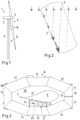
- Fig. 1 shows schematically a wind turbine 1 having a tower 2 and a nacelle 3.
- a rotor 4 of the wind turbine 1 is rotatably supported at the nacelle 3 by means of a hub 5.
- the rotor 4 comprises a number of rotor blades 6. In many cases the number of rotor blades 6 is three.
- a rotor blade 6 When a rotor blade 6 is to be inspected or repaired, it is usually moved into a safe position, for example in which it points downwardly in the direction of gravity. The edge of the rotor blade 6 is adjusted so that the wind cannot produce forces onto the rotor blade. When a wind turbine having three rotor blades 6 is used, the other two rotor blades point diagonally upwards.
- a maintenance platform 8 is used which is shown in a top view in Fig. 3 .
- the blade maintenance platform 8 comprises a frame which is built by a number of platform sections 9-17, at least some of which are hinged together.
- the platform 8 comprises a tower end 18 which during operation faces the tower 2 and a front end 19 which is in operation farther away from the tower 2.
- the maintenance platform 8 comprises a blade access area 20 which is structured and arranged to accommodate the blade 6 of the wind turbine 1.
- At least the platform sections 9, 17 at the front end 19 can be moved away from each other, so that the blade access area 20 is opened. In many cases the platform sections 9, 13, 16, 17 can be moved as well. However, this depends on the specific construction of the platform 8.
- the maintenance platform 8 is usually hoisted along the tower 2. When the necessary height is reached and the blade access area 20 is opened by moving the platform sections 9, 17 away from each other, the maintenance platform 8 can be moved away from the tower, so that the blade 6 can enter the blade access area 20. The platform sections 9, 17 can then be closed again.
- sealing means 21 are provided which are structured and arranged to contact the blade 6.
- the sealing means 21 comprise a number of suction cups 22 with which the sealing means 21 can be fixed to the blade 6 by suction, i.e., by a pressure below atmospheric pressure.
- the suction cups 22 are positioned below the sealing means 21.
- the sealing means 21 are provided at the platform segment 15. However, it is clear that other platform sections, in particular platform sections 10-12 and 14-16 can be provided with sealing means 21 as well. As it is shown in Fig. 3 , the sealing means 21 have a width which may be larger than the corresponding width of the platform section 15.
- the sealing means 21 comprise a leading edge 23 and a trailing edge 24.
- the trailing edge 24 is arranged towards the tower end 18 of the maintenance platform 8.
- the sealing means 21 are slightly inclined downwardly from the leading edge 23 to the trailing edge 24, so that rainwater or other water running down the blade 6 flows over the sealing means 21 towards the trailing edge 24 and from there through the blade access area 20 to the ground.
- the sealing means 21 comprise a drain path 25 (illustrated as an arrow) opening into the blade access area 20.
- the drain path 25 is the area on the sealing means 21 in which rainwater flows from the blade 6 to the blade access area 20.
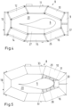
- Fig. 4 shows a view similar to Fig. 3 . However, the sealing means 21 and covers of the platform sections 9-17 have been removed, so that some safety means 26 can be seen.
- the safety means 26 (only the corresponding enclosure wall 26 is labelled in platform section 16) form a kind of protection protecting an operator.
- the platform 8 On the side facing away from the blade access area 20 the platform 8 comprises walls, for example in form of a canvas or the like. Together with a floor 39 ( Fig. 8 ) and a cover 40 ( Fig. 10 ) they form a protection against bad weather conditions. The space enclosed by the walls, the floor 39 and the cover 40 is still open to the blade access area.
- lateral wall elements 44, 45 are provided between the sealing means 21 and the platform 8. These lateral wall elements 44, 45 can extend over the floor 38 of the platform. They can be movable and, for example, can be folded or deformed in another way to be adapted to different distances between the blade 6 and the platform 8. They are arranged below the sealing means 21 in the direction of gravity, so that no rainwater can enter the working space.
- the lateral wall elements can have a distance to each other (in a direction from the trailing edge 18 to the leading edge 19 of the platform 8) which is smaller than the extension of the sealing means 21 in the same direction. This distance can be adapted to the size of the working space required or wanted, so that there is a great flexibility in the size of the working space.
- Platform section 15 is provided with an extendable bottom cover 27 which can be moved towards the blade 6, for example in form of a canvas so that the working space is also closed from the bottom.
- Fig. 5 shows the working platform 8 in a condition in which another area on the surface of the blade 6 is to be inspected or to be repaired.
- other sealing means 28 are provided at the platform sections 16 and further sealing means 29 are provided at platform section 10.
- a cover 30 is used at the leading edge 31 of the blade 6 to cover a triangular gap which may occur between the sealing means 28, 29. It is also possible to move sealing means 21 in the position shown for sealing means 28.
- sealing means 28, 29 are inclined towards the respective trailing edges 32, 33 which are closer to the tower end 18, so that water running down the blade 6 can directly flow into the blade access area 20.
- Fig. 6 shows a situation, in which nearly the whole blade access area 20 is covered by sealing means 21, 28, 29, 29a, 29b, 29c with exception of a small area 34 through which rainwater can directly flow to the ground.
- the drain path is again shown by arrows 25.
- the small cover 30 is again provided at the end of the platform 8 opposite the trailing edge 18.
- Fig. 7 shows more details of the sealing means 21.
- the other sealing means 28, 29 are of a similar construction. It should be noted that each platform section can be provided with its own sealing means 21. However, it is also possible, that at least one sealing means 21 is movable from one platform section to another one.
- the sealing means 21 comprises a carrier 35 carrying the suction cups 22. Furthermore, the carrier 35 carries a sealing element 36, for example in form of an inflatable tube or another flexible element. Furthermore, the carrier 35 is connected to a support element 37. The support element 37 is connected to the platform section 15. A roof element 38 is connected to the support element 37. The roof element 38 can be folded or rolled, as it is shown in Fig. 10 . The roof element 38 can be changed from a working stage (on the right-hand side of the blade 6 in Fig. 10 ) to a stowing stage as shown on the left-hand side of the blade 6 in Fig. 10 ).
- the working platform sections 9-17 have the floor 39 which is shown in Fig. 8 and the cover 40 which is shown in Fig. 10 .
- the roof element 38 covers a distance between the cover 40 and the blade 6. As can be seen in Fig. 10 , the roof element 38 is arranged at a lower height in the direction of gravity than the cover 40.
- the roof element 38 forms at least part of the drain path, so that water running down the surface of the blade 6 flows only over the roof element 38 and cannot flow over the cover 40, so that the water load onto the cover 40 is kept at a minimum.
- the sealing means 21 are inclined, i.e., a height in the direction of gravity at the trailing edge 7 of the blade 6 is lower than an end of the sealing means 21 at the leading edge 31 of the blade 6.
- the angle of inclination is in a range from 1° to 15°, for example, 5°.
- sealing element 21 is made from more than one sealing segment 41-43, as shown in Fig. 9 , the sealing segments 41-43 are arranged in a staircase and overlap each other, so that water is directed to the trailing edge of the blade 7.
- Fig. 11 shows platform section 15 and the blade 6 in a schematic side view.
- the platform section 15 is provided with an outer wall 47.
- Such outer walls 47 and covers 40 are provided on all platform sections 9 - 17, so that an operator working on the platform 8 is already protected from bad weather conditions.
- the support element 37 is fixed to the blade 6 by means of the carrier 35.
- the roof 38 fixed to the support element 37 has been unfolded or unrolled to cover the distance between the blade 6 and the cover 40 of the platform section 15 thus forming a working chamber 46.
- the working chamber 46 is laterally closed by the wall elements 45 (and 44 on the opposite side, Fig. 12 and 13 ).
- the bottom of the working chamber 46 is closed by means of the bottom cover 27, so that the working chamber is even more protected than the rest of interior of the platform 8. In this working chamber 46 it is possible to produce an atmosphere having the desired temperature and humidity.
- Fig. 12 and 13 show schematically a top view (without cover 40) of the platform 8.
- Fig. 12 shows the working chamber 46 having a minimum size. Only the distance between the blade 6 and the platform section 15 is closed by the lateral wall elements 44, 45. In Fig 13 the lateral wall elements 44, 45 are extended over the floor 39 of the platform section 15, so that the working chamber 46 is larger and can be completely closed, even in the area of the floor 39 of the platform section 15.
Landscapes
- Engineering & Computer Science (AREA)
- Life Sciences & Earth Sciences (AREA)
- Sustainable Development (AREA)
- Sustainable Energy (AREA)
- Chemical & Material Sciences (AREA)
- Combustion & Propulsion (AREA)
- Mechanical Engineering (AREA)
- General Engineering & Computer Science (AREA)
- Wind Motors (AREA)
Description
- The present invention relates to a wind turbine blade maintenance platform comprising a frame having a blade access area structured and arranged to accommodate a blade of a wind turbine, a tower end, and a front end, and sealing means structured and arranged to contact the blade.
- Such a wind turbine blade maintenance platform is known, for example, from
EP 3 538 797 B1 -
DE 20 2016 106 250 U1 describes a sealing arrangement with a gap within a transverse direction of the gap and a gap length in longitudinal direction of the gap between a first and a second surface, wherein a strip-shaped sealing element is arranged in the first surface over the gap length in the longitudinal direction of the gap and is pressed by means of at least one fastening element onto the first surface for sealing processes, and wherein a flat sealing element for bridging the gap within the transverse direction of the gap is connected on one end of the stripe-shaped sealing element and on the other end of the second surface. -
WO 2017/194940 A1 describes an apparatus and method for repairing fibre-composite structures, wherein an enclosure is provided which can be sealed to the structure so that repair can be conducted at any desired time. The enclosure is large enough to enclose a desired work area with the apparatus hand and arms entering to carry out the work through hands and arm seals. -
US 2019/0162172 A1 describes a temporary maintenance enclosure for maintenance of at least part of a turbine blade. The enclosure comprises a platform arranged to border at least of the circumference of a blade. At least one wall and a roof are carried by the platform. The roof extends from the wall towards the blade, wherein the wall extends from the platform. Further, the enclosure comprises a flexible sheath which seals onto the blade to provide the sealed volume for maintenance of said blade. - The blades of a wind turbine need from time to time an inspection and, if necessary, also a maintenance or repair. To this end a maintenance platform is used which is usually hoisted from the bottom up to a height in which it encloses the wind turbine blade. The platform comprises a tower end which is directed to the tower of the wind turbine and a front end which is directed in the opposite direction. In some embodiments of a maintenance platform the front end can be open to allow the insertion of the blade into the blade access area.
- Once the blade is accommodated in the blade access area, the maintenance people can inspect the blade over the whole circumference. The inspection over the length of the blade is possible by raising or lowering the platform.
- Inspection and maintenance of the blade of the wind turbine must be possible under nearly all-weather conditions, in particular even when it is raining. However, rainwater running down the rotor blade makes inspection difficult and maintenance almost impossible. If a defect is to be repaired, this usually requires a dry surface of the rotor blade.
- The object underlying the invention is to provide a platform which allows working at the rotor blade even under bad weather conditions.
- This object is achieved with a wind turbine blade maintenance platform as described at the outset with the additional features according to
claim 1. - The sealing means comprise a drain path, wherein the drain path opens into the blade access area.
- The region of the rotor blade below the sealing means can be kept dry. However, since the sealing means comprise a drain path opening into the blade access area, the rainwater needs not to flow over a cover of the platform, but can be drained directly through the blade access area. The rainwater flowing down the blade is separated from the blade by means of the sealing means. It is then directly guided over the sealing means to the blade access area without flowing over the cover of the platform. The load of the rainwater on the platform can be kept small, since the time in which the water remains on the platform is short due to the short distance between the sealing means and the end of the drain path where the water flows into the blade access area. The area of the blade to be repaired can be held in a condition of the right humidity.
- In an embodiment of the invention the sealing means comprise a sealing area between a leading edge and a trailing edge of the sealing means, wherein the trailing edge is arranged facing the tower end of the platform and the drain path is arranged at the trailing edge. When a rotor blade has to be inspected or to be repaired, it is usually moved in a position in which it points downwardly in the direction of gravity. Many wind turbines have three blades, so that the remaining two blades point upwardly in the direction of gravity. In this position, rain is equally distributed over the area above the blades. Rain falls onto the blades and starts its flow along the blade. More and more water is collected as the flow moves towards the hub. Water from the two upper blades will pass the hub and flow along the downwards facing blade which is to be inspected or to be repaired. Due to the geometric designs and angle of hub and blade, a large portion of the water will start to flow on the trailing edge of the downwards facing blade. Thus, when the drain path is arranged at the trailing edge of the sealing means, the drain path is arranged in a position in which the most water is to be expected. When the blade is in position for maintenance, the trailing edge of the blade is usually directed to the tower of the wind turbine. The trailing edge of the sealing means and the trailing edge of the blade are in this case both arranged facing the tower of the wind turbine.
- In an embodiment of the invention the sealing means form an upper border of a working space, the working space being laterally closed in the blade access area by means of wall elements, in particular wall elements which can be placed in different positions. Thus, the working conditions within the working space can be made to meet the requirements, for example for repairing a glass fiber damage of the blade. In this case a certain humidity range and a certain temperature range is required. The working space is thus limited by the blade, a wall of the working space at the side opposite the blade and some wall elements between the blade and the wall at the side opposite the blade. The wall elements can be, for example, in form of a canvas. They can be shifted, moved or repositioned to adjust a size of the working space to requirements of a repair.
- In an embodiment of the invention the wall elements extend over a floor of the platform. In this case a rather small working space can be formed, wherein it is easier to maintain the desired conditions of humidity and temperature. Such a working space is in form of a "chamber" which needs not to be larger than necessary for the repair. The wall elements can be movable to adjust the size of the chamber according to the requirements.
- In an embodiment of the invention the sealing means comprise a sealing element structured and arranged to contact the blade and a roof element, wherein the roof element forms at least part of the drain path. The water running down the blade is separated from the surface of the blade by means of the sealing element and directed to the roof element. The water then can flow over the roof element to the drain path. The roof element covers a part of the blade access area and keeps it dry.
- In an embodiment of the invention the platform comprises a floor and a cover, wherein the roof element is arranged at a lower height in the direction of gravity than the cover. The floor is the element on which the operator can stand or walk. The cover is the upper limit of the working space in the direction of gravity, however, only in the area of the platform. In the blade access area, the upper limit of the working space is formed by the roof element, which can also be termed "temporary roof element". Thus, the water running down the blade is not directed over the cover but can flow directly over the roof element to the drain path. Thus, the risk of an untight cover through which water flowing down the blade can enter the working space between the bottom and the cover, can be kept small or even eliminated.
- In an embodiment of the invention a size of the roof element can be changed from a working state to a stowing state. Thus, when the roof element is not needed, it can be stowed in a position of the working platform in which it does not disturb the inspection or maintenance of the blade.
- In an embodiment of the invention the roof element can be folded or rolled. The roof element can in particular have a pleat or wave form which is positive for a good water control.
- In an embodiment of the invention the roof element is connected to a support element. The roof element itself can then have a low mass. The mechanical stability is achieved by the support element.
- In an embodiment of the invention the support element is connected to the sealing element. The support element is used to move the sealing element towards the blade. When the sealing element contacts the blade, it can be held in contact with the plate by, for example, suction cups, so that the support element is also held in a stable position and the roof element can form a flow basis for the rainwater.
- In an embodiment of the invention the sealing means comprise at least one sealing segment. If the sealing segment is long enough to cover the desired working area, one segment is sufficient. If one segment is not sufficient to achieve the required rain protection, more segments can be used. The sealing segment can be fixed to a section of the platform. It is, however, also possible to move a sealing segment from one section to another section of the platform.
- In an embodiment of the invention the sealing means comprise at least two sealing segments, wherein one sealing segment overlaps another sealing segment. Thus, water flowing over the first segment falls down to the next segment, so that there is no risk of water flowing into the desired working area.
- In an embodiment of the invention the sealing segments are arranged in a staircase and rise away from the trailing edge. Thus, water flowing over the segment flows over the staircase down to the drain path.
- In an embodiment of the invention the sealing segment is shorter than an average width of the blade. In many cases a repair or maintenance of the whole width of the blade is not necessary. Thus, the sealing segment needs to cover only a part of the width of the blade. This allows for a time and cost saving construction.
- In an embodiment of the invention the platform comprises a number of platform sections and at least two platform sections are each provided with sealing means. Thus, the sealing means can be used in sections of the platform in which the workers are working. The area of the blade in which repairing can be performed, can be extended by connection of two or more sealing means or working spaces, wherein the connection of the sealing means produce a larger chamber. However, as long as a repair area is smaller than one chamber or working space, one sealing means, i.e., one chamber, is sufficient independently of where on the blade the repair area is positioned.
- In an embodiment of the invention at least one of the sealing means has an extension along the platform which is larger than the extension of the platform section in the same direction. Thus, it is possible that the sealing means of adjacent platform sections can overlap each other.
- In an embodiment of the invention the sealing means are inclined and descend in a direction to the tower end of the platform. Thus, water can run down an inclined surface so that the risk that water enters a working space is kept in a minimum.
- A preferred embodiment of the invention will now be described with reference to the drawing, in which:
- Fig. 1
- shows a schematical side view of a wind turbine,
- Fig. 2
- shows a detail B of
Fig. 1 , - Fig. 3
- shows a top view of a maintenance platform in a working position,
- Fig. 4
- shows a view according to
Fig. 3 without a roof element, - Fig. 5
- shows a view similar to
Fig. 3 , however, with a working area at another position, - Fig. 6
- shows a top view of the maintenance platform to illustrate a drain path,
- Fig. 7
- shows schematically sealing means and a roof element,
- Fig. 8
- shows a side view of a part of the maintenance platform,
- Fig. 9
- shows schematically a staircase-like arrangement of sealing segments,
- Fig. 10
- shows a rotor blade having a repair area which is covered by a roof element,
- Fig. 11
- shows schematically a side view of a platform section and the blade,
- Fig.12
- shows a view similar to
Fig. 4 illustrating a working chamber; and - Fig. 13
- shows a view similar to
Fig. 12 illustrating another size of the working chamber - In all Figures the same elements are denoted with the same reference numerals.
-
Fig. 1 shows schematically awind turbine 1 having atower 2 and anacelle 3. A rotor 4 of thewind turbine 1 is rotatably supported at thenacelle 3 by means of ahub 5. The rotor 4 comprises a number ofrotor blades 6. In many cases the number ofrotor blades 6 is three. - When a
rotor blade 6 is to be inspected or repaired, it is usually moved into a safe position, for example in which it points downwardly in the direction of gravity. The edge of therotor blade 6 is adjusted so that the wind cannot produce forces onto the rotor blade. When a wind turbine having threerotor blades 6 is used, the other two rotor blades point diagonally upwards. - Under bad weather condition, rain is equally distributed over an area above the blades. Rain falling onto the blade starts to flow along the blade. More and more water is collected as the flow moves toward the
hub 5. Water from the two upper blades will pass thehub 5 and follow along the downwards facingblade 6. Due to the geometric design and angle ofhub 5 andblade 6, a large portion of the water will start its flow on the trailingedge 7 of therotor blade 6. This is schematically shown inFig. 2 in which the flow path of the rainwater is shown with dashed lines. Flowing further down theblade 6, the water flow will increase and continue to collect at the trailingedge 7. - From time to time, it is necessary to inspect the
blade 6 and, if a defect is detected, theblade 6 must be repaired. To this end amaintenance platform 8 is used which is shown in a top view inFig. 3 . - The
blade maintenance platform 8 comprises a frame which is built by a number of platform sections 9-17, at least some of which are hinged together. Theplatform 8 comprises atower end 18 which during operation faces thetower 2 and afront end 19 which is in operation farther away from thetower 2. Furthermore, themaintenance platform 8 comprises ablade access area 20 which is structured and arranged to accommodate theblade 6 of thewind turbine 1. - At least the
platform sections front end 19 can be moved away from each other, so that theblade access area 20 is opened. In many cases theplatform sections platform 8. Themaintenance platform 8 is usually hoisted along thetower 2. When the necessary height is reached and theblade access area 20 is opened by moving theplatform sections maintenance platform 8 can be moved away from the tower, so that theblade 6 can enter theblade access area 20. Theplatform sections - In order to produce a dry area on the surface of the
blade 6 in which a defect can be repaired, sealing means 21 are provided which are structured and arranged to contact theblade 6. To this end, the sealing means 21 comprise a number ofsuction cups 22 with which the sealing means 21 can be fixed to theblade 6 by suction, i.e., by a pressure below atmospheric pressure. The suction cups 22 are positioned below the sealing means 21. - In
Fig. 3 , the sealing means 21 are provided at theplatform segment 15. However, it is clear that other platform sections, in particular platform sections 10-12 and 14-16 can be provided with sealing means 21 as well. As it is shown inFig. 3 , the sealing means 21 have a width which may be larger than the corresponding width of theplatform section 15. - The sealing means 21 comprise a
leading edge 23 and a trailingedge 24. The trailingedge 24 is arranged towards thetower end 18 of themaintenance platform 8. The sealing means 21 are slightly inclined downwardly from the leadingedge 23 to the trailingedge 24, so that rainwater or other water running down theblade 6 flows over the sealing means 21 towards the trailingedge 24 and from there through theblade access area 20 to the ground. - In other words, the sealing means 21 comprise a drain path 25 (illustrated as an arrow) opening into the
blade access area 20. Thus, there is no water load on the covers of the platform section 9-17 stemming from water from theblade 6. Thedrain path 25 is the area on the sealing means 21 in which rainwater flows from theblade 6 to theblade access area 20. -
Fig. 4 shows a view similar toFig. 3 . However, the sealing means 21 and covers of the platform sections 9-17 have been removed, so that some safety means 26 can be seen. The safety means 26 (only the correspondingenclosure wall 26 is labelled in platform section 16) form a kind of protection protecting an operator. - On the side facing away from the
blade access area 20 theplatform 8 comprises walls, for example in form of a canvas or the like. Together with a floor 39 (Fig. 8 ) and a cover 40 (Fig. 10 ) they form a protection against bad weather conditions. The space enclosed by the walls, thefloor 39 and thecover 40 is still open to the blade access area. - In order to form a working space in which defined conditions of humidity and temperature can be maintained,
lateral wall elements 44, 45 (Fig.11 to 13 ) are provided between the sealing means 21 and theplatform 8. Theselateral wall elements floor 38 of the platform. They can be movable and, for example, can be folded or deformed in another way to be adapted to different distances between theblade 6 and theplatform 8. They are arranged below the sealing means 21 in the direction of gravity, so that no rainwater can enter the working space. The lateral wall elements can have a distance to each other (in a direction from the trailingedge 18 to the leadingedge 19 of the platform 8) which is smaller than the extension of the sealing means 21 in the same direction. This distance can be adapted to the size of the working space required or wanted, so that there is a great flexibility in the size of the working space. -
Platform section 15 is provided with anextendable bottom cover 27 which can be moved towards theblade 6, for example in form of a canvas so that the working space is also closed from the bottom. -
Fig. 5 shows the workingplatform 8 in a condition in which another area on the surface of theblade 6 is to be inspected or to be repaired. To this end other sealing means 28 are provided at theplatform sections 16 and further sealing means 29 are provided atplatform section 10. In addition, acover 30 is used at theleading edge 31 of theblade 6 to cover a triangular gap which may occur between the sealing means 28, 29. It is also possible to move sealing means 21 in the position shown for sealingmeans 28. - Again, the sealing means 28, 29 are inclined towards the
respective trailing edges tower end 18, so that water running down theblade 6 can directly flow into theblade access area 20. -
Fig. 6 shows a situation, in which nearly the wholeblade access area 20 is covered by sealingmeans small area 34 through which rainwater can directly flow to the ground. The drain path is again shown byarrows 25. At the end of theplatform 8 opposite the trailingedge 18 thesmall cover 30 is again provided. -
Fig. 7 shows more details of the sealing means 21. The other sealing means 28, 29 are of a similar construction. It should be noted that each platform section can be provided with its own sealing means 21. However, it is also possible, that at least one sealing means 21 is movable from one platform section to another one. - The sealing means 21 comprises a
carrier 35 carrying thesuction cups 22. Furthermore, thecarrier 35 carries a sealingelement 36, for example in form of an inflatable tube or another flexible element. Furthermore, thecarrier 35 is connected to asupport element 37. Thesupport element 37 is connected to theplatform section 15. Aroof element 38 is connected to thesupport element 37. Theroof element 38 can be folded or rolled, as it is shown inFig. 10 . Theroof element 38 can be changed from a working stage (on the right-hand side of theblade 6 inFig. 10 ) to a stowing stage as shown on the left-hand side of theblade 6 inFig. 10 ). - The working platform sections 9-17 have the
floor 39 which is shown inFig. 8 and thecover 40 which is shown inFig. 10 . Theroof element 38 covers a distance between thecover 40 and theblade 6. As can be seen inFig. 10 , theroof element 38 is arranged at a lower height in the direction of gravity than thecover 40. Theroof element 38 forms at least part of the drain path, so that water running down the surface of theblade 6 flows only over theroof element 38 and cannot flow over thecover 40, so that the water load onto thecover 40 is kept at a minimum. - As can be seen in
Fig. 8 , the sealing means 21 are inclined, i.e., a height in the direction of gravity at the trailingedge 7 of theblade 6 is lower than an end of the sealing means 21 at theleading edge 31 of theblade 6. The angle of inclination is in a range from 1° to 15°, for example, 5°. - When the sealing
element 21 is made from more than one sealing segment 41-43, as shown inFig. 9 , the sealing segments 41-43 are arranged in a staircase and overlap each other, so that water is directed to the trailing edge of theblade 7. -
Fig. 11 shows platform section 15 and theblade 6 in a schematic side view. Theplatform section 15 is provided with anouter wall 47. Suchouter walls 47 and covers 40 are provided on all platform sections 9 - 17, so that an operator working on theplatform 8 is already protected from bad weather conditions. Thesupport element 37 is fixed to theblade 6 by means of thecarrier 35. Theroof 38 fixed to thesupport element 37 has been unfolded or unrolled to cover the distance between theblade 6 and thecover 40 of theplatform section 15 thus forming a workingchamber 46. The workingchamber 46 is laterally closed by the wall elements 45 (and 44 on the opposite side,Fig. 12 and 13 ). The bottom of the workingchamber 46 is closed by means of thebottom cover 27, so that the working chamber is even more protected than the rest of interior of theplatform 8. In this workingchamber 46 it is possible to produce an atmosphere having the desired temperature and humidity. -
Fig. 12 and 13 show schematically a top view (without cover 40) of theplatform 8.Fig. 12 shows the workingchamber 46 having a minimum size. Only the distance between theblade 6 and theplatform section 15 is closed by thelateral wall elements Fig 13 thelateral wall elements floor 39 of theplatform section 15, so that the workingchamber 46 is larger and can be completely closed, even in the area of thefloor 39 of theplatform section 15.
Claims (15)
- Wind turbine blade maintenance platform (8) comprising a frame having a blade access area (20) structured and arranged to accommodate a blade (6) of a wind turbine (1), a tower end (18), and a front end (19), a cover (40), and sealing means (21, 28, 29) structured and arranged to contact the blade (6), and the sealing means (21, 28, 29) comprise a drain path (25), characterized in that
the drain path (25) opens into the blade access area (20) such that rainwater flowing down the blade (6) is separated from the blade (6) by means of the sealing means (21, 28, 29) and is then directly guided over the sealing means (21, 28, 29) to the blade access area (20) without flowing over the cover (40) of the platform (8). - Maintenance platform according to claim 1, characterized in that the sealing means (21, 28, 29) comprise a sealing area between a leading edge (23) and a trailing edge (24) of the sealing means (21, 28, 29), wherein the trailing edge (24) is arranged facing the tower end (18) of the platform (8) and the drain path (25) is arranged at the trailing edge (24).
- Maintenance platform according to claim 1 or 2, characterized in that the sealing means form an upper border of a working space, wherein the working space is laterally closed in the blade access area (20) by means of wall elements, in particular wall elements which can be placed in different positions.
- Maintenance platform according to claim 3, characterized in that the wall elements extend over a floor (39) of the platform (8).
- Maintenance platform according to any of claims 1 to 4, characterized in that sealing means (21, 28, 29) comprise a sealing element (36) structured and arranged to contact the blade (6) and a roof element (38), wherein the roof element (38) forms at least part of the drain path (25).
- Maintenance platform according to claim 5, characterized in that the platform (8) comprises a floor (39) and a cover (40), wherein the roof element (38) is arranged at a lower height in the direction of gravity than the cover (40).
- Maintenance platform according to claim 5 or 6, characterized in that a size of the roof element (38) can be changed from a working state to a stowing state, in particular that the roof element (38) can be folded or rolled.
- Maintenance platform according to any of claims 5 to 7, characterized in that the roof element (38) is connected to a support element (37).
- Maintenance platform according to claim 8, characterized in that the support element (37) is connected to the sealing element (36).
- Maintenance platform according to any of claims 1 to 9, characterized in that the sealing means (21, 28, 29) comprise at least one sealing segment (41-43).
- Maintenance platform according to claim 10, characterized in that the sealing means (21, 28, 29) comprise at least two sealing segments (41-43), wherein one sealing segment (41, 42) overlaps another sealing segment (42, 43), in particular in a staircase and rise away from the trailing edge (24).
- Maintenance platform according to claim 10 or 11, characterized in that the sealing segment (41-43) is shorter than an average width of the blade (6).
- Maintenance platform according to any of claims 1 to 12, characterized in that the platform (8) comprises a number of platform sections (9-17) and at least two platform sections (9-17) are each provided with sealing means (21, 28, 29).
- Maintenance platform according to claim 13, characterized in that at least one of the sealing means (21, 28, 29) has an extension along the platform (8) which is larger than the extension of the platform section (9-17) in the same direction.
- Maintenance platform according to any of claims 1 to 14, characterized in that the sealing means (21, 28, 29) are inclined and descend in a direction to the tower end (18) of the platform (8).
Priority Applications (10)
| Application Number | Priority Date | Filing Date | Title |
|---|---|---|---|
| ES22152901T ES3017139T3 (en) | 2022-01-24 | 2022-01-24 | Wind turbine blade maintenance platform |
| DK22152901.9T DK4215747T3 (en) | 2022-01-24 | 2022-01-24 | WIND TURBINE BLADES MAINTENANCE PLATFORM |
| PL22152901.9T PL4215747T3 (en) | 2022-01-24 | 2022-01-24 | WIND TURBINE BLADE MAINTENANCE PLATFORM |
| EP22152901.9A EP4215747B1 (en) | 2022-01-24 | 2022-01-24 | Wind turbine blade maintenance platform |
| PT221529019T PT4215747T (en) | 2022-01-24 | 2022-01-24 | Wind turbine blade maintenance platform |
| CN202380017435.4A CN118591688A (en) | 2022-01-24 | 2023-01-16 | Wind turbine blade repair platform |
| CA3242567A CA3242567A1 (en) | 2022-01-24 | 2023-01-16 | WIND TURBINE BLADE MAINTENANCE PLATFORM |
| US18/730,985 US12473893B2 (en) | 2022-01-24 | 2023-01-16 | Wind turbine blade maintenance platform |
| AU2023210405A AU2023210405B2 (en) | 2022-01-24 | 2023-01-16 | Wind turbine blade maintenance platform |
| PCT/EP2023/050796 WO2023139005A1 (en) | 2022-01-24 | 2023-01-16 | Wind turbine blade maintenance platform |
Applications Claiming Priority (1)
| Application Number | Priority Date | Filing Date | Title |
|---|---|---|---|
| EP22152901.9A EP4215747B1 (en) | 2022-01-24 | 2022-01-24 | Wind turbine blade maintenance platform |
Publications (2)
| Publication Number | Publication Date |
|---|---|
| EP4215747A1 EP4215747A1 (en) | 2023-07-26 |
| EP4215747B1 true EP4215747B1 (en) | 2025-01-22 |
Family
ID=80001301
Family Applications (1)
| Application Number | Title | Priority Date | Filing Date |
|---|---|---|---|
| EP22152901.9A Active EP4215747B1 (en) | 2022-01-24 | 2022-01-24 | Wind turbine blade maintenance platform |
Country Status (10)
| Country | Link |
|---|---|
| US (1) | US12473893B2 (en) |
| EP (1) | EP4215747B1 (en) |
| CN (1) | CN118591688A (en) |
| AU (1) | AU2023210405B2 (en) |
| CA (1) | CA3242567A1 (en) |
| DK (1) | DK4215747T3 (en) |
| ES (1) | ES3017139T3 (en) |
| PL (1) | PL4215747T3 (en) |
| PT (1) | PT4215747T (en) |
| WO (1) | WO2023139005A1 (en) |
Families Citing this family (2)
| Publication number | Priority date | Publication date | Assignee | Title |
|---|---|---|---|---|
| EP3995693A1 (en) | 2020-11-10 | 2022-05-11 | PP Energy ApS | Temporary enclosure for at least a part of a rotor blade |
| EP4215747B1 (en) | 2022-01-24 | 2025-01-22 | PP Energy ApS | Wind turbine blade maintenance platform |
Family Cites Families (66)
| Publication number | Priority date | Publication date | Assignee | Title |
|---|---|---|---|---|
| US1658670A (en) | 1927-04-06 | 1928-02-07 | Corbett Theodore | Platform support for suspended scaffolds |
| US2118330A (en) | 1937-02-17 | 1938-05-24 | Kerlow Steel Flooring Co | Grating expansion joint for bridges |
| US3121470A (en) | 1962-05-11 | 1964-02-18 | Allen W Stone | Protective covering for scaffolding |
| US3452764A (en) | 1967-09-18 | 1969-07-01 | Loren D Bell | Pipeline welder's tent |
| US3991583A (en) | 1973-04-10 | 1976-11-16 | Scurlock John T | Method of providing an underwater enclosure |
| US4620612A (en) | 1983-07-31 | 1986-11-04 | Nisso Sangyo Co., Ltd. | Expansible corridor |
| US4821844A (en) | 1988-04-11 | 1989-04-18 | Huffman Cary A | Outrigger for scaffolding |
| US5038889A (en) | 1990-10-29 | 1991-08-13 | Jankowski Steven R | Scaffold enclosure |
| DE4336016A1 (en) | 1993-10-22 | 1995-04-27 | Langer Ruth Geb Layher | Corner joint training |
| SE507910C2 (en) | 1996-06-19 | 1998-07-27 | Jonsereds Miljoesystem Ab | Structure coverage system |
| DE19909698C2 (en) | 1998-09-22 | 2001-06-28 | Siebert Antonius J | Device for carrying out repairs and services, in particular on rotor blades of wind turbines |
| BR9914015A (en) | 1998-09-22 | 2001-07-03 | Antonius Siebert | Device to perform repair and maintenance work on blades and rotors in wind power plants |
| DE10118906B4 (en) | 2001-05-25 | 2009-04-09 | Müller, Holger | Apparatus and method for coating rotor blades of wind turbines |
| WO2004011163A1 (en) | 2002-07-26 | 2004-02-05 | Mintie Corporation | Environmental control unit |
| DE10311674B4 (en) | 2003-03-11 | 2007-02-01 | aeroconcept Ingenieurgesellschaft für Luftfahrttechnik und Faserverbundtechnologie mbH | maintenance platform |
| NZ548485A (en) | 2003-12-30 | 2009-06-26 | Pp Energy Aps | Device for enabling access to a structure above ground level |
| DE202004016460U1 (en) | 2004-10-25 | 2004-12-23 | Geo. Gleistein & Sohn Gmbh | Device for exchanging a rotor blade on a wind power machine has a carrier a holder and a connected cable lifting unit |
| US20060225960A1 (en) | 2005-04-12 | 2006-10-12 | Ferlin Keith A | Enclosed scaffolding assembly |
| CA2510944A1 (en) | 2005-06-28 | 2006-12-28 | Aluma Enterprises Inc. | Sheet securing scaffold clamp |
| DK200501312A (en) | 2005-09-21 | 2007-03-22 | Lm Glasfiber As | Wing fasteners |
| NL1030193C1 (en) | 2005-10-14 | 2007-04-17 | Walter Johannes Corneli Maanen | Protective canopy for building used during e.g. roof repair work, comprises cover secured to scaffolding extending above roof |
| US8490749B2 (en) | 2006-01-27 | 2013-07-23 | Pp Energy Aps | Device for enabling access to a structure above ground level |
| US20080302605A1 (en) | 2007-06-08 | 2008-12-11 | Andre St-Germain | Size adjustable platform for scaffolding |
| WO2009121792A2 (en) | 2008-04-02 | 2009-10-08 | Skyspider Aps | Maintenance platform for wind turbines |
| DE102008019680A1 (en) | 2008-04-11 | 2009-11-12 | Fraunhofer-Gesellschaft zur Förderung der angewandten Forschung e.V. | Inspection platform for wind turbine rotor blades comprises square frame made up of hinged sections which is fitted with opening system, allowing it to be fitted round blade and hauled up it on cables |
| WO2010112032A1 (en) | 2009-04-02 | 2010-10-07 | Lm Glasfiber A/S | Work platform |
| DE202009002054U1 (en) | 2009-04-08 | 2009-06-10 | L&L Rotorservice Gmbh | Weather and assembly protection device for rotor blades |
| US8062431B2 (en) * | 2009-06-16 | 2011-11-22 | General Electric Company | Method and apparatus for cleaning and de-icing wind turbine rotor blades |
| US8397382B2 (en) | 2010-01-08 | 2013-03-19 | Sky Climber Wind Solutions Llc | Method of repairing a wind turbine blade |
| DE102010011365B4 (en) | 2010-03-12 | 2016-01-21 | Andre Dochow | Weather protection for work platforms on propeller blades of wind turbines |
| US20110140437A1 (en) | 2010-05-26 | 2011-06-16 | Satish Vemuri | Self-supporting platform for a wind turbine |
| KR101285921B1 (en) * | 2010-05-31 | 2013-07-12 | 미츠비시 쥬고교 가부시키가이샤 | A blade end portion protecting bag and a rotor installing method for a wind turbine |
| NL2004871C2 (en) | 2010-06-10 | 2011-12-13 | Special Blade Service B V | MAIN WORKER FOR WIND TURBINES. |
| WO2011163498A2 (en) * | 2010-06-23 | 2011-12-29 | Jensen dustin | Wind turbine blade treatment apparatuses and methods |
| DE202011110372U1 (en) | 2010-09-15 | 2013-10-02 | Hailo-Werk Rudolf Loh Gmbh & Co. Kg | Rotor blade access system |
| US8579085B2 (en) | 2010-12-29 | 2013-11-12 | Sky Climber Llc | Suspended access chair with rescue system |
| CN103597203B (en) | 2011-06-09 | 2016-10-12 | Pp能源有限责任公司 | For connecting the lowering or hoisting gear of two rotor blade sections of wind turbine |
| DE102011111967B3 (en) | 2011-08-31 | 2013-01-10 | Nordex Energy Gmbh | Belt system for single blade assembly of a rotor blade or for star mounting a rotor to a wind turbine and method for this purpose |
| WO2013102460A1 (en) | 2012-01-02 | 2013-07-11 | Sidis Aps | Suspension system for wind turbines |
| DE102012001725A1 (en) | 2012-01-31 | 2013-08-01 | Fachhochschule Aachen | Climbing robot for masts |
| KR101454858B1 (en) | 2013-01-25 | 2014-10-27 | 삼성중공업 주식회사 | Blade maintanence robot of wind turbine |
| ES2485592B1 (en) | 2013-02-12 | 2015-05-20 | Global Energy Services Siemsa, S.A. | Lifting platform protective device for wind turbine maintenance |
| GB2518701B (en) | 2014-04-09 | 2015-09-02 | Ventura Wind Energy Ltd | Temporary maintenance enclosures and methods of maintaining turbine blades |
| US9447601B2 (en) | 2015-01-30 | 2016-09-20 | Jack J. Maillis | Portable environmental containment unit |
| US10718317B2 (en) | 2015-10-09 | 2020-07-21 | Vestas Wind Systems A/S | Wind turbine blade surface treatment apparatus |
| JP6154921B1 (en) | 2016-01-15 | 2017-06-28 | 日綜産業株式会社 | Gondola for blade maintenance in wind power generators |
| GB2550842A (en) * | 2016-05-11 | 2017-12-06 | Rotos 360 Ltd | Apparatus and method for repairing fibre-composite structures |
| DE102016121273B4 (en) | 2016-06-17 | 2023-01-05 | WP Systems GmbH | Rotor blade access system |
| US20190249649A1 (en) | 2016-07-12 | 2019-08-15 | Rope Robotics Aps | System with an apparatus on a wire, method of its operation, use thereof and a tool kit |
| US9828787B1 (en) | 2016-10-05 | 2017-11-28 | Winkler Canvas Ltd. | Covering tent for surrounding a wind turbine at its base during a grouting operation |
| DE202016106250U1 (en) | 2016-11-09 | 2016-11-22 | WP Systems GmbH | sealing arrangement |
| US10927816B2 (en) | 2017-02-17 | 2021-02-23 | Siemens Gamesa Renewable Energy A/S | Method and cover for covering an opening in a component of a wind turbine |
| EP4234113B1 (en) | 2017-02-27 | 2026-04-29 | Lebo Robotics, Inc. | Method for performing maintenance on a wind turbine blade |
| CN107035630B (en) | 2017-06-27 | 2019-03-01 | 深圳市晓控通信科技有限公司 | It is a kind of for cleaning the intelligent machine device of blade of wind-driven generator |
| EP3438375A1 (en) | 2017-08-01 | 2019-02-06 | Pressurehab Services Ltd | Methods and systems for performing rope access maintenance operations in vertical structures |
| EP3587807A1 (en) | 2018-06-25 | 2020-01-01 | Siemens Gamesa Renewable Energy A/S | Inflatable component for service or installation of a wind turbine module |
| US11525435B2 (en) | 2018-09-17 | 2022-12-13 | Pp Energy Aps | Water intrusion prevention system for turbine blades |
| CN111173692A (en) | 2019-12-31 | 2020-05-19 | 上海扩博智能技术有限公司 | A maintenance instrument carry device for fan blade |
| WO2021242158A1 (en) | 2020-05-26 | 2021-12-02 | Kjell Lindskog | Arrangement for work on blades or wings at a wind turbine |
| NL2026805B1 (en) | 2020-10-30 | 2022-06-21 | Ampelmann Holding B V | Device, system and method for forming a temporary support structure for maintenance crew for a blade of a wind turbine, method of performing maintenance, wind turbine blade, wind turbine and wind turbine park |
| EP3995693A1 (en) | 2020-11-10 | 2022-05-11 | PP Energy ApS | Temporary enclosure for at least a part of a rotor blade |
| US20250003394A1 (en) | 2021-07-09 | 2025-01-02 | Bladerobots A/S | Robotic device and method for repairing leading edge damage on a wind turbine blade with environmental controls |
| ES2980675T3 (en) | 2021-10-04 | 2024-10-02 | General Electric Renovables Espana Sl | Devices and procedures for mitigating vibrations in wind turbines |
| EP4160007A1 (en) | 2021-10-04 | 2023-04-05 | General Electric Renovables España S.L. | Devices and methods for mitigating vibrations in wind turbines |
| EP4215747B1 (en) | 2022-01-24 | 2025-01-22 | PP Energy ApS | Wind turbine blade maintenance platform |
| CN115949557B (en) | 2023-01-05 | 2023-12-19 | 南通奥里斯特机械有限公司 | High-strength wind power generation fan blade part-mounted locking sleeve and use method thereof |
-
2022
- 2022-01-24 EP EP22152901.9A patent/EP4215747B1/en active Active
- 2022-01-24 PT PT221529019T patent/PT4215747T/en unknown
- 2022-01-24 DK DK22152901.9T patent/DK4215747T3/en active
- 2022-01-24 PL PL22152901.9T patent/PL4215747T3/en unknown
- 2022-01-24 ES ES22152901T patent/ES3017139T3/en active Active
-
2023
- 2023-01-16 CA CA3242567A patent/CA3242567A1/en active Pending
- 2023-01-16 AU AU2023210405A patent/AU2023210405B2/en active Active
- 2023-01-16 US US18/730,985 patent/US12473893B2/en active Active
- 2023-01-16 CN CN202380017435.4A patent/CN118591688A/en active Pending
- 2023-01-16 WO PCT/EP2023/050796 patent/WO2023139005A1/en not_active Ceased
Also Published As
| Publication number | Publication date |
|---|---|
| PL4215747T3 (en) | 2025-05-19 |
| US12473893B2 (en) | 2025-11-18 |
| AU2023210405A1 (en) | 2024-08-08 |
| ES3017139T3 (en) | 2025-05-12 |
| DK4215747T3 (en) | 2025-03-31 |
| CA3242567A1 (en) | 2023-07-27 |
| CN118591688A (en) | 2024-09-03 |
| WO2023139005A1 (en) | 2023-07-27 |
| EP4215747A1 (en) | 2023-07-26 |
| AU2023210405B2 (en) | 2026-04-09 |
| PT4215747T (en) | 2025-03-21 |
| US20250101959A1 (en) | 2025-03-27 |
Similar Documents
| Publication | Publication Date | Title |
|---|---|---|
| US12473893B2 (en) | Wind turbine blade maintenance platform | |
| CN102066749B (en) | Paneling of nacelle of wind energy installation | |
| EP2366846B1 (en) | Openable covering construction for pergolas, verandas and the like | |
| US7192252B2 (en) | Safety device for a wind turbine | |
| US11143168B2 (en) | Rotor blade inspection rig | |
| EP4073926A1 (en) | Foldable solar panel assembly | |
| US12504005B2 (en) | Temporary enclosure for at least a part of a rotor blade | |
| US12404841B2 (en) | Device, system and method for forming a temporary support structure for maintenance crew for a blade of a wind turbine, method of performing maintenance, wind turbine blade, wind turbine and wind turbine park | |
| US10596600B2 (en) | Technologies for material separation | |
| US20210032870A1 (en) | Covering device with mobile panels, in particular for a pergola | |
| CN115088523B (en) | Movable open type sunlight greenhouse | |
| US20110268572A1 (en) | Hide-away windmill | |
| NL2022584B1 (en) | System for on-site maintenance of a turbine blade of a land or sea-based wind turbine, and method of using such a system for performing maintenance | |
| CN217872134U (en) | Municipal construction pipe shed | |
| KR102139016B1 (en) | Rooftop waterproofing method using asphalt shingle and flashing protecting cover | |
| US1823289A (en) | Housing equipment for aircraft | |
| CN209163256U (en) | A kind of exhaust apparatus of ventilation clerestory replacement easy to repair | |
| CN223923191U (en) | Offshore wind power blade detection and repair personnel operation platform device | |
| NL2032171B1 (en) | A support structure, a wind turbine blade, a wind turbine and a method | |
| EP4621157A1 (en) | Crossbeam and pillar arrangement for pergola structures | |
| EP4476413B1 (en) | An openable terrace canopy | |
| CN115002561A (en) | Active energy-saving communication base station | |
| CN118855295A (en) | Fully enclosed folding roof tent | |
| HK40035048A (en) | A maintenance enclosure and method for maintaining wind turbine blades | |
| GB2544734A (en) | Apparatus for covering a sports surface |
Legal Events
| Date | Code | Title | Description |
|---|---|---|---|
| PUAI | Public reference made under article 153(3) epc to a published international application that has entered the european phase |
Free format text: ORIGINAL CODE: 0009012 |
|
| STAA | Information on the status of an ep patent application or granted ep patent |
Free format text: STATUS: EXAMINATION IS IN PROGRESS |
|
| 17P | Request for examination filed |
Effective date: 20221220 |
|
| AK | Designated contracting states |
Kind code of ref document: A1 Designated state(s): AL AT BE BG CH CY CZ DE DK EE ES FI FR GB GR HR HU IE IS IT LI LT LU LV MC MK MT NL NO PL PT RO RS SE SI SK SM TR |
|
| GRAP | Despatch of communication of intention to grant a patent |
Free format text: ORIGINAL CODE: EPIDOSNIGR1 |
|
| STAA | Information on the status of an ep patent application or granted ep patent |
Free format text: STATUS: GRANT OF PATENT IS INTENDED |
|
| INTG | Intention to grant announced |
Effective date: 20240913 |
|
| P01 | Opt-out of the competence of the unified patent court (upc) registered |
Free format text: CASE NUMBER: APP_53181/2024 Effective date: 20240924 |
|
| GRAS | Grant fee paid |
Free format text: ORIGINAL CODE: EPIDOSNIGR3 |
|
| GRAA | (expected) grant |
Free format text: ORIGINAL CODE: 0009210 |
|
| STAA | Information on the status of an ep patent application or granted ep patent |
Free format text: STATUS: THE PATENT HAS BEEN GRANTED |
|
| AK | Designated contracting states |
Kind code of ref document: B1 Designated state(s): AL AT BE BG CH CY CZ DE DK EE ES FI FR GB GR HR HU IE IS IT LI LT LU LV MC MK MT NL NO PL PT RO RS SE SI SK SM TR |
|
| REG | Reference to a national code |
Ref country code: GB Ref legal event code: FG4D |
|
| REG | Reference to a national code |
Ref country code: CH Ref legal event code: EP |
|
| REG | Reference to a national code |
Ref country code: IE Ref legal event code: FG4D |
|
| REG | Reference to a national code |
Ref country code: DE Ref legal event code: R096 Ref document number: 602022009678 Country of ref document: DE |
|
| REG | Reference to a national code |
Ref country code: PT Ref legal event code: SC4A Ref document number: 4215747 Country of ref document: PT Date of ref document: 20250321 Kind code of ref document: T Free format text: AVAILABILITY OF NATIONAL TRANSLATION Effective date: 20250317 |
|
| REG | Reference to a national code |
Ref country code: DK Ref legal event code: T3 Effective date: 20250326 |
|
| PGFP | Annual fee paid to national office [announced via postgrant information from national office to epo] |
Ref country code: AT Payment date: 20250417 Year of fee payment: 4 |
|
| REG | Reference to a national code |
Ref country code: ES Ref legal event code: FG2A Ref document number: 3017139 Country of ref document: ES Kind code of ref document: T3 Effective date: 20250512 |
|
| REG | Reference to a national code |
Ref country code: NL Ref legal event code: MP Effective date: 20250122 |
|
| PG25 | Lapsed in a contracting state [announced via postgrant information from national office to epo] |
Ref country code: NL Free format text: LAPSE BECAUSE OF FAILURE TO SUBMIT A TRANSLATION OF THE DESCRIPTION OR TO PAY THE FEE WITHIN THE PRESCRIBED TIME-LIMIT Effective date: 20250122 |
|
| PG25 | Lapsed in a contracting state [announced via postgrant information from national office to epo] |
Ref country code: RS Free format text: LAPSE BECAUSE OF FAILURE TO SUBMIT A TRANSLATION OF THE DESCRIPTION OR TO PAY THE FEE WITHIN THE PRESCRIBED TIME-LIMIT Effective date: 20250422 |
|
| PG25 | Lapsed in a contracting state [announced via postgrant information from national office to epo] |
Ref country code: FI Free format text: LAPSE BECAUSE OF FAILURE TO SUBMIT A TRANSLATION OF THE DESCRIPTION OR TO PAY THE FEE WITHIN THE PRESCRIBED TIME-LIMIT Effective date: 20250122 |
|
| REG | Reference to a national code |
Ref country code: LT Ref legal event code: MG9D |
|
| PG25 | Lapsed in a contracting state [announced via postgrant information from national office to epo] |
Ref country code: NO Free format text: LAPSE BECAUSE OF FAILURE TO SUBMIT A TRANSLATION OF THE DESCRIPTION OR TO PAY THE FEE WITHIN THE PRESCRIBED TIME-LIMIT Effective date: 20250422 Ref country code: IS Free format text: LAPSE BECAUSE OF FAILURE TO SUBMIT A TRANSLATION OF THE DESCRIPTION OR TO PAY THE FEE WITHIN THE PRESCRIBED TIME-LIMIT Effective date: 20250522 |
|
| REG | Reference to a national code |
Ref country code: AT Ref legal event code: MK05 Ref document number: 1761643 Country of ref document: AT Kind code of ref document: T Effective date: 20250122 |
|
| PG25 | Lapsed in a contracting state [announced via postgrant information from national office to epo] |
Ref country code: HR Free format text: LAPSE BECAUSE OF FAILURE TO SUBMIT A TRANSLATION OF THE DESCRIPTION OR TO PAY THE FEE WITHIN THE PRESCRIBED TIME-LIMIT Effective date: 20250122 |
|
| PG25 | Lapsed in a contracting state [announced via postgrant information from national office to epo] |
Ref country code: LV Free format text: LAPSE BECAUSE OF FAILURE TO SUBMIT A TRANSLATION OF THE DESCRIPTION OR TO PAY THE FEE WITHIN THE PRESCRIBED TIME-LIMIT Effective date: 20250122 |
|
| PG25 | Lapsed in a contracting state [announced via postgrant information from national office to epo] |
Ref country code: GR Free format text: LAPSE BECAUSE OF FAILURE TO SUBMIT A TRANSLATION OF THE DESCRIPTION OR TO PAY THE FEE WITHIN THE PRESCRIBED TIME-LIMIT Effective date: 20250423 Ref country code: BG Free format text: LAPSE BECAUSE OF FAILURE TO SUBMIT A TRANSLATION OF THE DESCRIPTION OR TO PAY THE FEE WITHIN THE PRESCRIBED TIME-LIMIT Effective date: 20250122 |
|
| PG25 | Lapsed in a contracting state [announced via postgrant information from national office to epo] |
Ref country code: AT Free format text: LAPSE BECAUSE OF FAILURE TO SUBMIT A TRANSLATION OF THE DESCRIPTION OR TO PAY THE FEE WITHIN THE PRESCRIBED TIME-LIMIT Effective date: 20250122 |
|
| REG | Reference to a national code |
Ref country code: CH Ref legal event code: PL |
|
| PG25 | Lapsed in a contracting state [announced via postgrant information from national office to epo] |
Ref country code: SE Free format text: LAPSE BECAUSE OF FAILURE TO SUBMIT A TRANSLATION OF THE DESCRIPTION OR TO PAY THE FEE WITHIN THE PRESCRIBED TIME-LIMIT Effective date: 20250122 |
|
| PG25 | Lapsed in a contracting state [announced via postgrant information from national office to epo] |
Ref country code: LU Free format text: LAPSE BECAUSE OF NON-PAYMENT OF DUE FEES Effective date: 20250124 |
|
| PG25 | Lapsed in a contracting state [announced via postgrant information from national office to epo] |
Ref country code: SM Free format text: LAPSE BECAUSE OF FAILURE TO SUBMIT A TRANSLATION OF THE DESCRIPTION OR TO PAY THE FEE WITHIN THE PRESCRIBED TIME-LIMIT Effective date: 20250122 |
|
| PG25 | Lapsed in a contracting state [announced via postgrant information from national office to epo] |
Ref country code: MC Free format text: LAPSE BECAUSE OF FAILURE TO SUBMIT A TRANSLATION OF THE DESCRIPTION OR TO PAY THE FEE WITHIN THE PRESCRIBED TIME-LIMIT Effective date: 20250122 |
|
| PG25 | Lapsed in a contracting state [announced via postgrant information from national office to epo] |
Ref country code: IT Free format text: LAPSE BECAUSE OF FAILURE TO SUBMIT A TRANSLATION OF THE DESCRIPTION OR TO PAY THE FEE WITHIN THE PRESCRIBED TIME-LIMIT Effective date: 20250122 |
|
| PG25 | Lapsed in a contracting state [announced via postgrant information from national office to epo] |
Ref country code: BE Free format text: LAPSE BECAUSE OF NON-PAYMENT OF DUE FEES Effective date: 20250131 |
|
| PG25 | Lapsed in a contracting state [announced via postgrant information from national office to epo] |
Ref country code: CH Free format text: LAPSE BECAUSE OF NON-PAYMENT OF DUE FEES Effective date: 20250131 |
|
| PG25 | Lapsed in a contracting state [announced via postgrant information from national office to epo] |
Ref country code: EE Free format text: LAPSE BECAUSE OF FAILURE TO SUBMIT A TRANSLATION OF THE DESCRIPTION OR TO PAY THE FEE WITHIN THE PRESCRIBED TIME-LIMIT Effective date: 20250122 Ref country code: CZ Free format text: LAPSE BECAUSE OF FAILURE TO SUBMIT A TRANSLATION OF THE DESCRIPTION OR TO PAY THE FEE WITHIN THE PRESCRIBED TIME-LIMIT Effective date: 20250122 |
|
| REG | Reference to a national code |
Ref country code: BE Ref legal event code: MM Effective date: 20250131 Ref country code: DE Ref legal event code: R097 Ref document number: 602022009678 Country of ref document: DE |
|
| PG25 | Lapsed in a contracting state [announced via postgrant information from national office to epo] |
Ref country code: RO Free format text: LAPSE BECAUSE OF FAILURE TO SUBMIT A TRANSLATION OF THE DESCRIPTION OR TO PAY THE FEE WITHIN THE PRESCRIBED TIME-LIMIT Effective date: 20250122 |
|
| PG25 | Lapsed in a contracting state [announced via postgrant information from national office to epo] |
Ref country code: SK Free format text: LAPSE BECAUSE OF FAILURE TO SUBMIT A TRANSLATION OF THE DESCRIPTION OR TO PAY THE FEE WITHIN THE PRESCRIBED TIME-LIMIT Effective date: 20250122 |
|
| PLBE | No opposition filed within time limit |
Free format text: ORIGINAL CODE: 0009261 |
|
| STAA | Information on the status of an ep patent application or granted ep patent |
Free format text: STATUS: NO OPPOSITION FILED WITHIN TIME LIMIT |
|
| 26N | No opposition filed |
Effective date: 20251023 |
|
| PGFP | Annual fee paid to national office [announced via postgrant information from national office to epo] |
Ref country code: GB Payment date: 20251204 Year of fee payment: 5 |
|
| PGFP | Annual fee paid to national office [announced via postgrant information from national office to epo] |
Ref country code: FR Payment date: 20251208 Year of fee payment: 5 |
|
| PG25 | Lapsed in a contracting state [announced via postgrant information from national office to epo] |
Ref country code: IE Free format text: LAPSE BECAUSE OF NON-PAYMENT OF DUE FEES Effective date: 20250124 |
|
| PGFP | Annual fee paid to national office [announced via postgrant information from national office to epo] |
Ref country code: PL Payment date: 20251212 Year of fee payment: 5 |
|
| PGFP | Annual fee paid to national office [announced via postgrant information from national office to epo] |
Ref country code: ES Payment date: 20260213 Year of fee payment: 5 |
|
| PGFP | Annual fee paid to national office [announced via postgrant information from national office to epo] |
Ref country code: DK Payment date: 20260113 Year of fee payment: 5 Ref country code: DE Payment date: 20251203 Year of fee payment: 5 |
|
| PGFP | Annual fee paid to national office [announced via postgrant information from national office to epo] |
Ref country code: PT Payment date: 20260109 Year of fee payment: 5 |