EP4215744A1 - Door arrangement for a wind turbine, door locking device and wind turbine - Google Patents
Door arrangement for a wind turbine, door locking device and wind turbine Download PDFInfo
- Publication number
- EP4215744A1 EP4215744A1 EP22382035.8A EP22382035A EP4215744A1 EP 4215744 A1 EP4215744 A1 EP 4215744A1 EP 22382035 A EP22382035 A EP 22382035A EP 4215744 A1 EP4215744 A1 EP 4215744A1
- Authority
- EP
- European Patent Office
- Prior art keywords
- door
- component
- central component
- attaching means
- stationary component
- Prior art date
- Legal status (The legal status is an assumption and is not a legal conclusion. Google has not performed a legal analysis and makes no representation as to the accuracy of the status listed.)
- Granted
Links
Images

Classifications
-
- E—FIXED CONSTRUCTIONS
- E05—LOCKS; KEYS; WINDOW OR DOOR FITTINGS; SAFES
- E05C—BOLTS OR FASTENING DEVICES FOR WINGS, SPECIALLY FOR DOORS OR WINDOWS
- E05C17/00—Devices for holding wings open; Devices for limiting opening of wings or for holding wings open by a movable member extending between frame and wing; Braking devices, stops or buffers, combined therewith
- E05C17/02—Devices for holding wings open; Devices for limiting opening of wings or for holding wings open by a movable member extending between frame and wing; Braking devices, stops or buffers, combined therewith by mechanical means
- E05C17/44—Devices for holding wings open; Devices for limiting opening of wings or for holding wings open by a movable member extending between frame and wing; Braking devices, stops or buffers, combined therewith by mechanical means with a device carried on the wing for frictional or like engagement with a fixed flat surface, e.g. for holding wings open or closed by retractable feet
-
- F—MECHANICAL ENGINEERING; LIGHTING; HEATING; WEAPONS; BLASTING
- F03—MACHINES OR ENGINES FOR LIQUIDS; WIND, SPRING, OR WEIGHT MOTORS; PRODUCING MECHANICAL POWER OR A REACTIVE PROPULSIVE THRUST, NOT OTHERWISE PROVIDED FOR
- F03D—WIND MOTORS
- F03D13/00—Assembly, mounting or commissioning of wind motors; Arrangements specially adapted for transporting wind motor components
- F03D13/20—Arrangements for mounting or supporting wind motors; Masts or towers for wind motors
-
- E—FIXED CONSTRUCTIONS
- E05—LOCKS; KEYS; WINDOW OR DOOR FITTINGS; SAFES
- E05B—LOCKS; ACCESSORIES THEREFOR; HANDCUFFS
- E05B63/00—Locks or fastenings with special structural characteristics
- E05B63/24—Arrangements in which the fastening members which engage one another are mounted respectively on the wing and the frame and are both movable, e.g. for release by moving either of them
- E05B63/244—Arrangements in which the fastening members which engage one another are mounted respectively on the wing and the frame and are both movable, e.g. for release by moving either of them the striker being movable for latching, the bolt for unlatching, or vice versa
- E05B63/246—Emergency release from inside by releasing the striker
-
- F—MECHANICAL ENGINEERING; LIGHTING; HEATING; WEAPONS; BLASTING
- F03—MACHINES OR ENGINES FOR LIQUIDS; WIND, SPRING, OR WEIGHT MOTORS; PRODUCING MECHANICAL POWER OR A REACTIVE PROPULSIVE THRUST, NOT OTHERWISE PROVIDED FOR
- F03D—WIND MOTORS
- F03D80/00—Details, components or accessories not provided for in groups F03D1/00 - F03D17/00
- F03D80/50—Maintenance or repair
-
- Y—GENERAL TAGGING OF NEW TECHNOLOGICAL DEVELOPMENTS; GENERAL TAGGING OF CROSS-SECTIONAL TECHNOLOGIES SPANNING OVER SEVERAL SECTIONS OF THE IPC; TECHNICAL SUBJECTS COVERED BY FORMER USPC CROSS-REFERENCE ART COLLECTIONS [XRACs] AND DIGESTS
- Y02—TECHNOLOGIES OR APPLICATIONS FOR MITIGATION OR ADAPTATION AGAINST CLIMATE CHANGE
- Y02E—REDUCTION OF GREENHOUSE GAS [GHG] EMISSIONS, RELATED TO ENERGY GENERATION, TRANSMISSION OR DISTRIBUTION
- Y02E10/00—Energy generation through renewable energy sources
- Y02E10/70—Wind energy
- Y02E10/72—Wind turbines with rotation axis in wind direction
Definitions
- the present invention relates to a door arrangement for a wind turbine, comprising a door with an outer side and an inner side and a door locking device for locking and unlocking the closed door by coupling and decoupling the closed door with a stationary component of the door arrangement or the wind turbine.
- Doors of wind turbines are provided to protect the interior of the wind turbine from disadvantageous weather conditions like humidity and/or extreme temperatures. Usually, such doors are lockable to ensure that unauthorized persons cannot enter the wind turbine. However, persons who are currently in the interior of the wind turbine e.g. for maintenance work might have to leave the wind turbine. Particularly in case of a fire alarm or another threatening situation it is necessary that staff working within the wind turbine can leave the interior as quick as possible. This might be problematic if the door is currently locked. Another problem regarding lockable doors of wind turbines is that persons might be locked in the wind turbine accidentally.
- a door arrangement as initially described is characterized in that the door locking device comprises a central component, an attaching means and a connecting means, wherein the central component is attached to the stationary component by the attaching means and connectable and disconnectable with the door by the connecting means for locking and unlocking the door by a person being at the outer side, wherein the attaching means is manually releasable by a person being at the inner side for disconnecting the central component from the stationary component to unlock the door without tools.
- the present invention is based on the idea that the central component constitutes two mechanical connections, namely a first connection connecting the central component and the door and a second connection connecting the central component and the stationary component. Under normal conditions, the connection between the central component and the stationary component is closed. However, this connection can be opened by the person being at the inner side of the door or, in other words, within the interior of the wind turbine by hand without using any kind of tool to manually unlock the door and to be able to escape from the wind turbine in case of an emergency or in case the person has been accidentally locked in.
- the attaching means can be manually released or opened by the person being at the inner side.
- the word "manually” means that the attaching means or the connection between the central component and the stationary component can be released or opened by hand only, i.e., by just using the fingers without any mechanical tools like screw drivers, wrenches, crowbars or the like.
- the door can be or comprise a door plate.
- the door can consist of metal and/or wood and/or plastic or another suitable material.
- the door can be mounted at a tower of the wind turbine, particularly on the stationary component. Being in the closed position, i.e., being in the state covering an entrance hole of the wind turbine, the door is lockable. In the locked state and from the outer side, the door cannot be opened without a respective key or other entrance means for locking and unlocking the door.
- the door is a swing door which can be pivoted around a, particularly vertical, axis for bringing it from the open into the closed position and vice versa.
- the door is held by hinges which are arranged on the door plate.
- the door can be a sliding door which is movable along a, particularly horizontal, axis.
- the door can be held by and guided on at least one sliding rail, which can be attached to the stationary component.
- the stationary component can be a, particularly rectangular, door frame which is fitted into the entrance opening of the tower of the wind turbine, particularly by means of concrete or other suitable filling materials.
- the stationary component is not a separate element but a part of a wall or the tower of the wind turbine surrounding the door or the entrance opening, respectively.
- the attaching means can comprise a handling section which the person being at the inner side can grasp by fingers for disconnecting the central component from the stationary component. Hence, the person being at the inner side is able to disconnect the central component and the stationary component just by releasing the attaching means with the help of the handling section.
- the handling section can be a clamp, a hand wheel, a lever, a knurled knob, a star knob or another manually manipulatable means. Hence, manually disconnecting the central component from the stationary component can be done by tilting the clamp or turning or rotating the hand wheel or lever or the like.
- the central component can comprise a plate and a receiving element, wherein the receiving element is attached to the plate and the plate is attached to the stationary component by the attaching means, wherein the receiving element is adapted to receive the connecting means for connecting the central component with the door.
- the receiving element can be attached to the plate by screws, gluing, welding or the like.
- the plate and/or the receiving element can consist of metal, particularly of steel, or any other suitable material.
- the attaching means can be a or can comprise at least one knob stud which extends through the plate and which is manually unscrewable from a threaded hole of the stationary component for disconnecting the central component from the stationary component to manually unlock the door by the person being at the inner side.
- the knob stud consists of a threaded bolt with a, particularly knurled and/or star-shaped, knob on the one end and which can be screwed into the threaded hole of the stationary component with its other end.
- the bolt comprises an external screw thread
- the threaded hole comprises an internal screw thread which fit to each other.
- the plate comprises a hole which has the same diameter as or a larger diameter than the external screw thread of the bolt of the knob stud.
- the attaching means is or comprises three knob studs extending through the plate and being manually unscrewable from a threaded hole of the stationary component each, wherein the three threaded holes are arranged triangularly to each other.
- three knob studs with three threaded holes means that the central component is attached to the stationary component at three points, wherein, if these points are arranged at the three corners of a triangle, no movement or clearance of the central component occurs, when the three knob studs are tightened carefully.
- the material and the dimensions of the knob studs can be such that, when all three knob studs are hand-tightened, they collectively provide a clamping force, i.e., a force pressing the plate or central component, respectively, against the stationary component, which is between 5 and 30 kN, particularly 15 kN. This force is large enough to keep the central component in place during a normal operational state.
- the central component as an attaching plate, which is attached to the stationary component comprise a lug
- the attaching means is or comprises a pin which extends through the lugs and which can be manually pulled out from the lugs for disconnecting the central component from the stationary component to manually unlock the door by the person being at the inner side.
- the pin can comprise a pin head which additionally can avoid that the pin falls down through the lugs.
- the longitudinal directions of bores of the lugs are in line which each other to allow the pin to be inserted into the lugs.
- the connecting means can be or can comprise at least one threaded bolt which extends through the door and which is unscrewable from a threaded hole of the receiving element for disconnecting the central component from the door to unlock the door by the person being at the outer side.
- the connecting means cannot be unscrewed manually but only with the help of a certain tool.
- the receiving element can be a, particularly metallic, solid and block-like component comprising the threaded hole.
- the threaded bolt comprises an external screw thread and the threaded hole of the receiving element an internal screw thread which fit to each other.
- the door comprises a hole with a diameter which is equal to or larger than the outer diameter of the external screw thread of the threaded bolt.
- a screw head of the threaded bolt can hold the door in position.
- the screw head can be located within a counterbore hole on the outer side of the door or within a supporting element which is attached to the outer side.
- the threaded bolt can be unscrewable from and screwable into the threaded hole of the central component with a hex wrench or a wrench comprising a nut.
- the threaded bolt can be a security bolt which can be unscrewed with special tools only. Respective security systems of screwing connections which cannot be opened by common tools are known and provided by manufacturers like, e.g., McGard.
- a door locking device for locking an unlocking a closed door with an outer side and an inner side by coupling and decoupling the door with a stationary component
- the door locking device comprises a central component, an attaching means and a connecting means
- the attaching means is adapted to attach the central component to the stationary component
- the connecting means is adapted to connect and disconnect the central component with the door for locking and unlocking the door by a person being at the outer side
- the attaching means comprises a handling section which allows the attaching means to be manually released by a person being at the inner side for disconnecting the central component from the stationary component to unlock the door without tools.
- the attaching means of the door locking device can comprise a handling section which the person being at the inner side can grasp by the fingers for disconnecting the central component from the stationary component, wherein the handling section is particularly a knurled knob or a star knob.
- a wind turbine comprising at least one door arrangement according to the description above and/or at least one door locking device according to the preceding section of the description. All advantages, features and aspects which are explained with respect to the door arrangement according to the present invention and to the locking device according to the present invention also apply to the wind turbine according to the present invention and vice versa.
- the door arrangement constitutes an entrance door on the bottom of a tower of the wind turbine.
- the entrance door allows persons to enter the wind turbine from the outside.
- the tower of the wind turbine can be made of concrete and/or metal or other suitable materials.
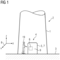
- Fig. 1 shows a bottom section of a tower 1 of a wind turbine 2 according to the present invention, which is located on a ground 3.
- the tower 1 comprises an entrance door 4 which is realised by means of a door arrangement 5 according to the present invention with a locking device 6 according to the present invention.
- the door arrangement 5 comprises a plate-like door 7 which can be pivoted from an open into a closed position and vice versa by help of hinges 24 (see fig. 5 ). While all figures show the door 7 in the closed position, the dashed lines in fig. 5 indicate the door 7 in the open position. Regarding the closed position, the door 7 comprises an outer side 9 facing the environment and an inner side 10 facing an interior 11 of the wind turbine 2.
- the door locking device 6 of the door arrangement 5 comprises a central component 12, which is used for locking and unlocking the closed door 7.
- the central component 12 comprises a metallic plate 13 and a metallic, block-like and solid receiving element 14 which is attached to the plate 13 by welding.
- the central component 12 provides two releasable mechanical connections, namely a first connection connecting the central component 12 and the door 7 and a second connection connecting the central component 12 and a stationary component 15.
- the stationary component 15 is a door frame which fits into a respective opening of a concrete wall 16 of the tower 1. Alternatively, the stationary component 15 is the wall 16 itself.
- the central component 12 is connectable and disconnectable with the door 7 by the connecting means 18. In a normal operational state, connecting and disconnecting the first connection corresponds to locking and unlocking the door 7.
- the central component 12 is attached to the stationary component 15 of the door arrangement 5 by an attaching means 17.
- the second connection or the attaching means 17, respectively In the normal operational state, the second connection or the attaching means 17, respectively, is in a closed state. However, the attaching means 17 can also be released to unlock the door 7, particularly in emergency situations.
- the attaching means 17 is manually releasable by a person 20 being at the inner side 10 of the door 7.
- the person 20 at the inner side 10 is able to open the connection between the central component 12 and the stationary component 15 just by hand.
- this component comprises a handling section 21 which the person 20 being at the inner side 10 can grasp by the fingers for disconnecting the central component 12 from the stationary component 15 to unlock the door 7 without tools.
- the connecting means 18 can be opened just from the outer side 20, the attaching means 17 allows to manually unlock the door 7 from the inner side 10 or the interior 11 of the wind turbine 2. This is advantageous, particularly in the case of a fire alarm or if the person 20 has been accidentally locked into the wind turbine 2.
- the attaching means 17 comprises three knob studs 22 which extend through the plate 13 and which are manually unscrewable from a threaded hole 23 of the stationary component 15 each.
- Each of the knob studs 22 comprises a threaded bolt 25 with an external screw thread which fits an internal screw thread of the threaded hole 23 of the stationary component 15.
- the plate 13 comprises a hole, wherein the bolt 25 runs through this hole.
- the knob stud 22 furthermore comprises a, particularly knurled, star knob 26, which constitutes the handling section 21.
- the threaded holes 23 are arranged triangularly to each other at the stationary component 15 (see fig. 4 ). If all three knob studs 22 are tightened by hand properly, they provide a clamping force of approximately 15 kN which presses the plate 13 towards the stationary component 15.
- the connecting means 18 is a threaded bolt 27 with a screw head 28.
- the threaded bolt 27 extends through the door 7 and, if the door 7 is locked, screwed into a threaded hole 29 of the receiving element 14.
- the threaded bolt 27 comprises an external screw thread and the threaded hole 29 an internal screw thread which fit to each other.
- the screw head 28 holds the door 7 in position and is located within a counterbore hole of a conical supporting element 30 which is attached on the outer side 9 of the door 7.
- the threaded bolt 27 is screwed into the threaded hole 29 of the receiving element 14.
- the person 19 being at the outer side 9 of the door 7 can lock/unlock the door 7 by screwing/unscrewing the threaded bolt 27 into the threaded hole 29 by a tool.
- the tool can be a hex-wrench which can be inserted into a respective hex hole of the screw head 28.
- the tool comprises a special nut, which only fits to the respective screw head 28 to provide a security system. In this security system, the door 7 can be unlocked by the respective special tool or nut only.
- Figs. 6 and 7 show another possible embodiment of the door locking device 6.
- the central component 12 comprises the plate 13, the receiving element 14 and, in contrast to the previous embodiment, a cylindrical lug 31.
- An attaching plate 32 is attached to the stationary component 15.
- the attaching plate 32 comprises a plate 33 for screwing the attaching plate 32 on the stationary component 15.
- the attaching plate 32 furthermore comprises a cylindrical lug 34, wherein borings through the lugs 31, 34 are arranged coaxially.
- the attaching means 17 is a pin 35 which extends through the lugs 31, 34.
- the pin 35 comprises a pin head 36 to avoid that the pin 35 falls through the lugs 31, 34.
- the attaching means 12 or the pin 35, respectively, can be released by the person 20 being at the inner side 10 to unlock the door 7 without tools just by pulling the pin 35 out of the lugs 31, 34 with the hand, which is indicated by the arrow 37 in fig. 6 .
- the pin head 36 constitutes the handling portion 21.
- the door 7 comprises an automatically closing latch-notch-connection to bring the door 7 into a closed but unlocked state.
- a door handle 38 is provided to open this connection from the inner side 10.
- a key hole 39 is provided on the outer side 9 .
- the latch-notch-connection can be opened from the outer side 9 by a respective key.
Landscapes
- Engineering & Computer Science (AREA)
- Mechanical Engineering (AREA)
- Life Sciences & Earth Sciences (AREA)
- Sustainable Development (AREA)
- Sustainable Energy (AREA)
- Chemical & Material Sciences (AREA)
- Combustion & Propulsion (AREA)
- General Engineering & Computer Science (AREA)
- Physics & Mathematics (AREA)
- Electromagnetism (AREA)
- Structural Engineering (AREA)
- Connection Of Plates (AREA)
Abstract
Description
- The present invention relates to a door arrangement for a wind turbine, comprising a door with an outer side and an inner side and a door locking device for locking and unlocking the closed door by coupling and decoupling the closed door with a stationary component of the door arrangement or the wind turbine.
- Doors of wind turbines are provided to protect the interior of the wind turbine from disadvantageous weather conditions like humidity and/or extreme temperatures. Mostly, such doors are lockable to ensure that unauthorized persons cannot enter the wind turbine. However, persons who are currently in the interior of the wind turbine e.g. for maintenance work might have to leave the wind turbine. Particularly in case of a fire alarm or another threatening situation it is necessary that staff working within the wind turbine can leave the interior as quick as possible. This might be problematic if the door is currently locked. Another problem regarding lockable doors of wind turbines is that persons might be locked in the wind turbine accidentally.
- Hence, it is an object of the present invention to provide an enhanced concept regarding lockable doors for wind turbines.
- To solve this problem by means of the present invention, a door arrangement as initially described is characterized in that the door locking device comprises a central component, an attaching means and a connecting means, wherein the central component is attached to the stationary component by the attaching means and connectable and disconnectable with the door by the connecting means for locking and unlocking the door by a person being at the outer side, wherein the attaching means is manually releasable by a person being at the inner side for disconnecting the central component from the stationary component to unlock the door without tools.
- The present invention is based on the idea that the central component constitutes two mechanical connections, namely a first connection connecting the central component and the door and a second connection connecting the central component and the stationary component. Under normal conditions, the connection between the central component and the stationary component is closed. However, this connection can be opened by the person being at the inner side of the door or, in other words, within the interior of the wind turbine by hand without using any kind of tool to manually unlock the door and to be able to escape from the wind turbine in case of an emergency or in case the person has been accidentally locked in.
- It is essential for the present invention that the attaching means can be manually released or opened by the person being at the inner side. The word "manually" means that the attaching means or the connection between the central component and the stationary component can be released or opened by hand only, i.e., by just using the fingers without any mechanical tools like screw drivers, wrenches, crowbars or the like.
- The door can be or comprise a door plate. The door can consist of metal and/or wood and/or plastic or another suitable material. The door can be mounted at a tower of the wind turbine, particularly on the stationary component. Being in the closed position, i.e., being in the state covering an entrance hole of the wind turbine, the door is lockable. In the locked state and from the outer side, the door cannot be opened without a respective key or other entrance means for locking and unlocking the door.
- Particularly, the door is a swing door which can be pivoted around a, particularly vertical, axis for bringing it from the open into the closed position and vice versa. In this embodiment, the door is held by hinges which are arranged on the door plate. Alternatively, the door can be a sliding door which is movable along a, particularly horizontal, axis. In this embodiment, the door can be held by and guided on at least one sliding rail, which can be attached to the stationary component.
- The stationary component can be a, particularly rectangular, door frame which is fitted into the entrance opening of the tower of the wind turbine, particularly by means of concrete or other suitable filling materials. Alternatively, it is possible that the stationary component is not a separate element but a part of a wall or the tower of the wind turbine surrounding the door or the entrance opening, respectively.
- The attaching means can comprise a handling section which the person being at the inner side can grasp by fingers for disconnecting the central component from the stationary component. Hence, the person being at the inner side is able to disconnect the central component and the stationary component just by releasing the attaching means with the help of the handling section. The handling section can be a clamp, a hand wheel, a lever, a knurled knob, a star knob or another manually manipulatable means. Hence, manually disconnecting the central component from the stationary component can be done by tilting the clamp or turning or rotating the hand wheel or lever or the like.
- The central component can comprise a plate and a receiving element, wherein the receiving element is attached to the plate and the plate is attached to the stationary component by the attaching means, wherein the receiving element is adapted to receive the connecting means for connecting the central component with the door. The receiving element can be attached to the plate by screws, gluing, welding or the like. The plate and/or the receiving element can consist of metal, particularly of steel, or any other suitable material.
- The attaching means can be a or can comprise at least one knob stud which extends through the plate and which is manually unscrewable from a threaded hole of the stationary component for disconnecting the central component from the stationary component to manually unlock the door by the person being at the inner side. The knob stud consists of a threaded bolt with a, particularly knurled and/or star-shaped, knob on the one end and which can be screwed into the threaded hole of the stationary component with its other end. Hence, the bolt comprises an external screw thread and the threaded hole comprises an internal screw thread which fit to each other. The plate comprises a hole which has the same diameter as or a larger diameter than the external screw thread of the bolt of the knob stud.
- In a preferred embodiment, the attaching means is or comprises three knob studs extending through the plate and being manually unscrewable from a threaded hole of the stationary component each, wherein the three threaded holes are arranged triangularly to each other. Using three knob studs with three threaded holes means that the central component is attached to the stationary component at three points, wherein, if these points are arranged at the three corners of a triangle, no movement or clearance of the central component occurs, when the three knob studs are tightened carefully.
- The material and the dimensions of the knob studs can be such that, when all three knob studs are hand-tightened, they collectively provide a clamping force, i.e., a force pressing the plate or central component, respectively, against the stationary component, which is between 5 and 30 kN, particularly 15 kN. This force is large enough to keep the central component in place during a normal operational state.
- In an alternative embodiment, as well the central component as an attaching plate, which is attached to the stationary component, comprise a lug, wherein the attaching means is or comprises a pin which extends through the lugs and which can be manually pulled out from the lugs for disconnecting the central component from the stationary component to manually unlock the door by the person being at the inner side. For a better handling and to be able to easily remove the pin from the lugs, the pin can comprise a pin head which additionally can avoid that the pin falls down through the lugs. The longitudinal directions of bores of the lugs are in line which each other to allow the pin to be inserted into the lugs.
- The connecting means can be or can comprise at least one threaded bolt which extends through the door and which is unscrewable from a threaded hole of the receiving element for disconnecting the central component from the door to unlock the door by the person being at the outer side. In contrast to the attaching means, the connecting means cannot be unscrewed manually but only with the help of a certain tool.
- The receiving element can be a, particularly metallic, solid and block-like component comprising the threaded hole. The threaded bolt comprises an external screw thread and the threaded hole of the receiving element an internal screw thread which fit to each other. The door comprises a hole with a diameter which is equal to or larger than the outer diameter of the external screw thread of the threaded bolt.
- Referring to the locked state of the door, a screw head of the threaded bolt can hold the door in position. The screw head can be located within a counterbore hole on the outer side of the door or within a supporting element which is attached to the outer side.
- The threaded bolt can be unscrewable from and screwable into the threaded hole of the central component with a hex wrench or a wrench comprising a nut. The threaded bolt can be a security bolt which can be unscrewed with special tools only. Respective security systems of screwing connections which cannot be opened by common tools are known and provided by manufacturers like, e.g., McGard.
- To achieve the object of the present invention, a door locking device for locking an unlocking a closed door with an outer side and an inner side by coupling and decoupling the door with a stationary component is provided, wherein the door locking device comprises a central component, an attaching means and a connecting means, wherein the attaching means is adapted to attach the central component to the stationary component, wherein the connecting means is adapted to connect and disconnect the central component with the door for locking and unlocking the door by a person being at the outer side, wherein the attaching means comprises a handling section which allows the attaching means to be manually released by a person being at the inner side for disconnecting the central component from the stationary component to unlock the door without tools. All advantages, features and aspects explained above with respect to the door arrangement according to the present invention also apply to the door locking device according to the present invention and vice versa.
- The attaching means of the door locking device can comprise a handling section which the person being at the inner side can grasp by the fingers for disconnecting the central component from the stationary component, wherein the handling section is particularly a knurled knob or a star knob.
- The object of the present invention is further achieved by a wind turbine, comprising at least one door arrangement according to the description above and/or at least one door locking device according to the preceding section of the description. All advantages, features and aspects which are explained with respect to the door arrangement according to the present invention and to the locking device according to the present invention also apply to the wind turbine according to the present invention and vice versa.
- Preferably, the door arrangement constitutes an entrance door on the bottom of a tower of the wind turbine. The entrance door allows persons to enter the wind turbine from the outside. The tower of the wind turbine can be made of concrete and/or metal or other suitable materials.
- Other objects and features of the present invention will become apparent from the following detailed description considered in conjunction with the accompanying drawings. The drawings, however, are only principle sketches designed solely for the purpose of illustration and do not limit the invention. The drawings show:
- Fig. 1
- a bottom section of a tower of an embodiment of a wind turbine according to the present invention,
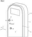
- Fig. 2
- a view on an outer side of a door of an embodiment of a door arrangement according to the present invention of the wind turbine of
fig. 1 , - Fig. 3
- a view on an inner side of the door of the door arrangement of the wind turbine of
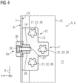
fig. 1 , - Fig. 4
- a vertical cut through the door arrangement along the line IV-IV of
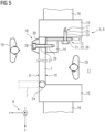
fig. 3 , - Fig. 5
- a horizontal cut through the door arrangement along the line V-V of
fig. 3 , - Fig. 6
- a view on an inner side of a door of another possible embodiment of a door arrangement of the wind turbine of
fig. 1 , and - Fig. 7
- a close-up view of the central component and a bottom bracket of the door arrangement of
fig. 6 . -
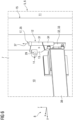
Fig. 1 shows a bottom section of atower 1 of a wind turbine 2 according to the present invention, which is located on aground 3. Thetower 1 comprises anentrance door 4 which is realised by means of a door arrangement 5 according to the present invention with alocking device 6 according to the present invention. - Details regarding a specific embodiment of the door arrangement 5 and the
door locking device 6 are explained in reference tofigs. 2 to 5 . The door arrangement 5 comprises a plate-like door 7 which can be pivoted from an open into a closed position and vice versa by help of hinges 24 (seefig. 5 ). While all figures show thedoor 7 in the closed position, the dashed lines infig. 5 indicate thedoor 7 in the open position. Regarding the closed position, thedoor 7 comprises anouter side 9 facing the environment and aninner side 10 facing an interior 11 of the wind turbine 2. - For a better orientation, all figures show a coordinate
system 8, wherein the x-axis points perpendicular away from theclosed door 7, the y-axis runs horizontally within the plane of the closed door and the z-axis points vertically upwards. - As can be seen particularly from
figures 3 to 5 , thedoor locking device 6 of the door arrangement 5 comprises acentral component 12, which is used for locking and unlocking theclosed door 7. Thecentral component 12 comprises ametallic plate 13 and a metallic, block-like and solid receivingelement 14 which is attached to theplate 13 by welding. - The
central component 12 provides two releasable mechanical connections, namely a first connection connecting thecentral component 12 and thedoor 7 and a second connection connecting thecentral component 12 and astationary component 15. Thestationary component 15 is a door frame which fits into a respective opening of aconcrete wall 16 of thetower 1. Alternatively, thestationary component 15 is thewall 16 itself. - Regarding the first connection, the
central component 12 is connectable and disconnectable with thedoor 7 by the connectingmeans 18. In a normal operational state, connecting and disconnecting the first connection corresponds to locking and unlocking thedoor 7. - Regarding the second connection, the
central component 12 is attached to thestationary component 15 of the door arrangement 5 by an attachingmeans 17. In the normal operational state, the second connection or the attachingmeans 17, respectively, is in a closed state. However, the attaching means 17 can also be released to unlock thedoor 7, particularly in emergency situations. - In the following, the aspects regarding the attaching
means 17, the connectingmeans 18 and the functional principle of the onedoor locking device 6 are disclosed in detail. Assuming that thelocking device 6 is in the normal operational state, i.e., that thecentral component 12 is connected with thestationary component 15 by the attachingmeans 17, aperson 19 being at theouter side 9 of the door 7 (seefigures 1 and5 ) can lock thedoor 7 by connecting it with thecentral component 12 using the connectingmeans 18. - Independent from this, the attaching
means 17 is manually releasable by aperson 20 being at theinner side 10 of thedoor 7. Thus, theperson 20 at theinner side 10 is able to open the connection between thecentral component 12 and thestationary component 15 just by hand. Regarding the manual opening of the attachingmeans 17, this component comprises a handling section 21 which theperson 20 being at theinner side 10 can grasp by the fingers for disconnecting thecentral component 12 from thestationary component 15 to unlock thedoor 7 without tools. - Although the connecting means 18 can be opened just from the
outer side 20, the attachingmeans 17 allows to manually unlock thedoor 7 from theinner side 10 or the interior 11 of the wind turbine 2. This is advantageous, particularly in the case of a fire alarm or if theperson 20 has been accidentally locked into the wind turbine 2. - As shown in
figures 4 and5 , the attachingmeans 17 comprises three knob studs 22 which extend through theplate 13 and which are manually unscrewable from a threadedhole 23 of thestationary component 15 each. Each of the knob studs 22 comprises a threadedbolt 25 with an external screw thread which fits an internal screw thread of the threadedhole 23 of thestationary component 15. Theplate 13 comprises a hole, wherein thebolt 25 runs through this hole. The knob stud 22 furthermore comprises a, particularly knurled, star knob 26, which constitutes the handling section 21. The threaded holes 23 are arranged triangularly to each other at the stationary component 15 (seefig. 4 ). If all three knob studs 22 are tightened by hand properly, they provide a clamping force of approximately 15 kN which presses theplate 13 towards thestationary component 15. - Referring particularly to
figures 4 and5 , the connectingmeans 18 is a threadedbolt 27 with ascrew head 28. The threadedbolt 27 extends through thedoor 7 and, if thedoor 7 is locked, screwed into a threadedhole 29 of the receivingelement 14. The threadedbolt 27 comprises an external screw thread and the threadedhole 29 an internal screw thread which fit to each other. Referring to the locked state of thedoor 7 again, thescrew head 28 holds thedoor 7 in position and is located within a counterbore hole of a conical supportingelement 30 which is attached on theouter side 9 of thedoor 7. The threadedbolt 27 is screwed into the threadedhole 29 of the receivingelement 14. - The
person 19 being at theouter side 9 of thedoor 7 can lock/unlock thedoor 7 by screwing/unscrewing the threadedbolt 27 into the threadedhole 29 by a tool. The tool can be a hex-wrench which can be inserted into a respective hex hole of thescrew head 28. Preferably, the tool comprises a special nut, which only fits to therespective screw head 28 to provide a security system. In this security system, thedoor 7 can be unlocked by the respective special tool or nut only. -
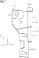
Figs. 6 and7 show another possible embodiment of thedoor locking device 6. In this embodiment, the same connecting means 18 as in the embodiment shown infigures 2 to 5 is provided. Thecentral component 12 comprises theplate 13, the receivingelement 14 and, in contrast to the previous embodiment, acylindrical lug 31. An attaching plate 32 is attached to thestationary component 15. Particularly, the attaching plate 32 comprises a plate 33 for screwing the attaching plate 32 on thestationary component 15. The attaching plate 32 furthermore comprises acylindrical lug 34, wherein borings through thelugs - The attaching means 17 is a pin 35 which extends through the
lugs lugs person 20 being at theinner side 10 to unlock thedoor 7 without tools just by pulling the pin 35 out of thelugs arrow 37 infig. 6 . Hence, in this embodiment, the pin head 36 constitutes the handling portion 21. - In both embodiments and independently from the
door locking device 6, thedoor 7 comprises an automatically closing latch-notch-connection to bring thedoor 7 into a closed but unlocked state. To open this connection from theinner side 10, adoor handle 38 is provided. On the outer side 9 akey hole 39 is provided. The latch-notch-connection can be opened from theouter side 9 by a respective key. - Although the present invention has been described in detail with reference to the preferred embodiment, the present invention is not limited by the disclosed examples from which the skilled person is able to derive other variations without departing from the scope of the invention.
Claims (13)
- Door arrangement for a wind turbine (2), comprising a door (7) with an outer side (9) and an inner side (10) and a door locking device (6) for locking and unlocking the closed door (7) by coupling and decoupling the closed door (7) with a stationary component (15) of the door arrangement (5) of the wind turbine (2), characterized in that the door locking device (6) comprises a central component (12), an attaching means (17) and a connecting means (18), wherein the central component (12) is attached to the stationary component (15) by the attaching means (17) and connectable and disconnectable with the door (7) by the connecting means (18) for locking and unlocking the door (7) by a person (19) being at the outer side (9), wherein the attaching means (17) is manually releasable by a person (20) being at the inner side (10) for disconnecting the central component (12) from the stationary component (15) to unlock the door (7) without tools.
- Door arrangement according to claim 1, characterized in that the attaching means (17) comprises a handling section (21) which the person (20) being at the inner side (10) can grasp by the fingers for disconnecting the central component (12) from the stationary component (15), wherein the handling section (21) is particularly a knurled knob or a star knob (26) .
- Door arrangement according to claim 1 or 2, characterized in that the central component (12) comprises a plate (13) and a receiving element (14), wherein the receiving element (14) is attached to the plate (13) and the plate (13) is attached to the stationary component (15) by the attaching means (17), wherein the receiving element (14) is adapted to receive the connecting means (18) for connecting the central component (12) with the door (7).
- Door arrangement according to claim 3, characterized in that the attaching means (17) is a or comprises at least one knob stud (22) which extends through the plate (13) and which is manually unscrewable from a threaded hole (23) of the stationary component (15) for disconnecting the central component (12) from the stationary component (15) to manually unlock the door by the person (20) being at the inner side (10) .
- Door arrangement according to claim 4, characterized in that the attaching means (17) is or comprises three knob studs (22) extending through the plate (13) and being manually unscrewable from a threaded hole (23) of the stationary component (15) each, wherein the three threaded holes (23) are arranged triangularly to each other.
- Door arrangement according to claim 3, characterized in that the central component (12) and an attaching plate (32), which is attached to the stationary component (15), comprise a lug (31, 34) each, wherein the attaching means (17) is or comprises a pin (35) which runs through the lugs (31, 34) and which can be pulled out from the lugs (31, 34) manually for disconnecting the central component (12) from the stationary component (15) to manually unlock the door by the person (20) being at the inner side (10).
- Door arrangement according to one of the claims 3 to 6, characterized in that the connecting means (18) is a or comprises at least one threaded bolt (27) which extends through the door (7) and which is unscrewable from a threaded hole (29) of the receiving element (14) for disconnecting the central component (12) from the door (7) to unlock the door (7) by the person (19) being at the outer side (9).
- Door arrangement according to claim 7, characterized in that the threaded bolt (27) is unscrewable from the threaded hole (29) of the central component (12) with a hex wrench or a wrench comprising a nut.
- Door arrangement according to one of the preceding claims, characterized in that the stationary component (15) is a door frame.
- Door locking device for locking and unlocking a closed door (7) with an outer side (9) and an inner side (10) by coupling and decoupling the door (7) with a stationary component (15), characterized in that the door locking device (6) comprises a central component (12), an attaching means (17) and a connecting means (18), wherein the attaching means (17) is adapted to attach the central component (12) to the stationary component (15), wherein the connecting means (18) is adapted to connect and disconnect the central component (12) with the door (7) for locking and unlocking the door (7) by a person (19) being at the outer side (9), wherein the attaching means (17) comprises a handling section (21) which allows the attaching means (17) to be manually released by a person (20) being at the inner side (10) for disconnecting the central component (12) from the stationary component (15) to unlock the door (7) without tools.
- Door locking device according to claim 10, characterized in that the attaching means (17) comprises a handling section (21) which the person (20) being at the inner side (10) can grasp by the fingers for disconnecting the central component (12) from the stationary component (15), wherein the handling section (21) is particularly a knurled knob or a star knob (26) .
- Wind turbine, comprising at least one door arrangement (5) according to one of the claims 1 to 9 and or at least one door locking device (6) according to claim 10 or 11.
- Wind turbine according to claim 12, characterized in that the door arrangement (5) constitutes an entrance door (4) on the bottom of a tower (1) of the wind turbine (2).
Priority Applications (2)
| Application Number | Priority Date | Filing Date | Title |
|---|---|---|---|
| EP22382035.8A EP4215744B1 (en) | 2022-01-20 | 2022-01-20 | Door arrangement for a wind turbine, door locking device and wind turbine |
| US18/095,884 US20230228135A1 (en) | 2022-01-20 | 2023-01-11 | Door arrangement for a wind turbine, door locking device and wind turbine |
Applications Claiming Priority (1)
| Application Number | Priority Date | Filing Date | Title |
|---|---|---|---|
| EP22382035.8A EP4215744B1 (en) | 2022-01-20 | 2022-01-20 | Door arrangement for a wind turbine, door locking device and wind turbine |
Publications (2)
| Publication Number | Publication Date |
|---|---|
| EP4215744A1 true EP4215744A1 (en) | 2023-07-26 |
| EP4215744B1 EP4215744B1 (en) | 2025-07-23 |
Family
ID=80222518
Family Applications (1)
| Application Number | Title | Priority Date | Filing Date |
|---|---|---|---|
| EP22382035.8A Active EP4215744B1 (en) | 2022-01-20 | 2022-01-20 | Door arrangement for a wind turbine, door locking device and wind turbine |
Country Status (2)
| Country | Link |
|---|---|
| US (1) | US20230228135A1 (en) |
| EP (1) | EP4215744B1 (en) |
Citations (3)
| Publication number | Priority date | Publication date | Assignee | Title |
|---|---|---|---|---|
| US2461426A (en) * | 1947-02-10 | 1949-02-08 | King Vernon Merton | Safety strike plate and release bar |
| US2533396A (en) * | 1946-06-28 | 1950-12-12 | Frank B Payne | Keeper |
| US6526788B2 (en) * | 2001-04-05 | 2003-03-04 | Kason Industries, Inc. | Walk-in freezer door handle and lock assembly |
Family Cites Families (21)
| Publication number | Priority date | Publication date | Assignee | Title |
|---|---|---|---|---|
| US1578779A (en) * | 1924-08-21 | 1926-03-30 | Alfred E Titus | Refrigerator-door lock |
| US1787296A (en) * | 1929-08-27 | 1930-12-30 | Wild Gunther Philip | Door fastener |
| US2473205A (en) * | 1947-11-13 | 1949-06-14 | Joseph J Jazwieck | Fire escape control mechanism |
| US2743953A (en) * | 1953-01-07 | 1956-05-01 | Maria V Marra | Latch keeper for refrigerator doors |
| FR1516770A (en) * | 1966-06-29 | 1968-02-05 | Fermod Ferrures Modernes | Safety lock for cold rooms and similar applications |
| US4431220A (en) * | 1981-07-02 | 1984-02-14 | Loughlin Robert W | Safety release for bar lock |
| US4540207A (en) * | 1983-08-29 | 1985-09-10 | The Vollrath Company | Refrigerator door pull and latch assembly |
| DE8330967U1 (en) * | 1983-10-28 | 1984-01-26 | Klein, Karl Adolf, 6000 Frankfurt | QUICK RELEASE DEVICE FOR A LOCKED DOOR |
| JPS60129460U (en) * | 1984-02-10 | 1985-08-30 | タキゲン製造株式会社 | Temporary locking device for refrigerators, etc. that can be unlocked inside the refrigerator |
| JPS613869U (en) * | 1984-06-14 | 1986-01-10 | タキゲン製造株式会社 | Temporary locking device for refrigerators, etc. that can be unlocked inside the refrigerator |
| US4838589A (en) * | 1987-08-21 | 1989-06-13 | Diamico John L | Apparatus to lock storm doors and avoid draft |
| US5026100A (en) * | 1989-09-19 | 1991-06-25 | General Dynamics Corporation | Lock release apparatus |
| US5104163A (en) * | 1991-08-09 | 1992-04-14 | Palmer Jr Clem L | Double self-latching, double-locking gate latch mechanism |
| US5462320A (en) * | 1994-04-15 | 1995-10-31 | Davis; Roland L. | Internally removable safety hasp system |
| US5711559A (en) * | 1994-04-15 | 1998-01-27 | Davis; Roland L. | Automobile trunk lid release |
| US5593192A (en) * | 1995-09-18 | 1997-01-14 | Stuchinsky; Yoram | Cabinet door latch |
| EP0959208A1 (en) * | 1998-05-11 | 1999-11-24 | Ki-Panel Produktion AB | Safety release assembly |
| DE102008012664A1 (en) * | 2008-01-30 | 2009-08-06 | Repower Systems Ag | Wind turbine and a tower or tower segment and a door frame for it |
| US9068376B2 (en) * | 2013-04-22 | 2015-06-30 | Kason Industries, Inc. | Strike for walk-in cold rooms |
| EP3926168A1 (en) * | 2020-06-17 | 2021-12-22 | Siemens Gamesa Renewable Energy A/S | Tower of a wind turbine |
| CN214943704U (en) * | 2021-04-30 | 2021-11-30 | 洁绿重工有限公司 | Wind turbine generator system tower section of thick bamboo door structure and wind turbine generator system tower section of thick bamboo |
-
2022
- 2022-01-20 EP EP22382035.8A patent/EP4215744B1/en active Active
-
2023
- 2023-01-11 US US18/095,884 patent/US20230228135A1/en not_active Abandoned
Patent Citations (3)
| Publication number | Priority date | Publication date | Assignee | Title |
|---|---|---|---|---|
| US2533396A (en) * | 1946-06-28 | 1950-12-12 | Frank B Payne | Keeper |
| US2461426A (en) * | 1947-02-10 | 1949-02-08 | King Vernon Merton | Safety strike plate and release bar |
| US6526788B2 (en) * | 2001-04-05 | 2003-03-04 | Kason Industries, Inc. | Walk-in freezer door handle and lock assembly |
Also Published As
| Publication number | Publication date |
|---|---|
| EP4215744B1 (en) | 2025-07-23 |
| US20230228135A1 (en) | 2023-07-20 |
Similar Documents
| Publication | Publication Date | Title |
|---|---|---|
| EP3260711B1 (en) | Fastener | |
| US5125861A (en) | Lifting eyebolt assembly | |
| US9500387B2 (en) | Duct access door | |
| CN108780985A (en) | Housing arrangements; components; and methods | |
| US20130004260A1 (en) | Connection means and lock mounting device with such connection means | |
| US8444033B2 (en) | Device for attaching accessories to bars, application to motor vehicle roof rail bars | |
| EP4215744B1 (en) | Door arrangement for a wind turbine, door locking device and wind turbine | |
| US6880792B2 (en) | Detachable arm limiting assembly | |
| US8813529B2 (en) | Anti-theft device for inverters | |
| EP1570147B1 (en) | An adjustable hinge assembly | |
| US6612631B1 (en) | Trench plate connector | |
| FI105288B (en) | Torque screw or torque nut | |
| US7862278B2 (en) | Anti-tamper device | |
| US9865408B2 (en) | Switch extension device and mounting assembly | |
| US10683678B2 (en) | Door with door fitting | |
| US4747302A (en) | Mounting fixture for end-of-train device or the like | |
| JP2969329B2 (en) | Scaffolding support fittings | |
| US8091285B1 (en) | Storm shutter fastener and quick release system for emergency egress | |
| GB2074291A (en) | Valve Locking Device | |
| CN2781112Y (en) | Ball valve capable of locking | |
| CN217020173U (en) | Open-close type hexagonal sleeve clamp | |
| CN218294132U (en) | Nut with anti-theft function | |
| CN212959696U (en) | Mounting tool for automatic locking and connecting device for rope end of steel wire rope | |
| KR100653970B1 (en) | Door lock | |
| GB2488002A (en) | A back plate with at least one fixing sleeve |
Legal Events
| Date | Code | Title | Description |
|---|---|---|---|
| PUAI | Public reference made under article 153(3) epc to a published international application that has entered the european phase |
Free format text: ORIGINAL CODE: 0009012 |
|
| STAA | Information on the status of an ep patent application or granted ep patent |
Free format text: STATUS: THE APPLICATION HAS BEEN PUBLISHED |
|
| AK | Designated contracting states |
Kind code of ref document: A1 Designated state(s): AL AT BE BG CH CY CZ DE DK EE ES FI FR GB GR HR HU IE IS IT LI LT LU LV MC MK MT NL NO PL PT RO RS SE SI SK SM TR |
|
| STAA | Information on the status of an ep patent application or granted ep patent |
Free format text: STATUS: REQUEST FOR EXAMINATION WAS MADE |
|
| 17P | Request for examination filed |
Effective date: 20240126 |
|
| RBV | Designated contracting states (corrected) |
Designated state(s): AL AT BE BG CH CY CZ DE DK EE ES FI FR GB GR HR HU IE IS IT LI LT LU LV MC MK MT NL NO PL PT RO RS SE SI SK SM TR |
|
| GRAP | Despatch of communication of intention to grant a patent |
Free format text: ORIGINAL CODE: EPIDOSNIGR1 |
|
| STAA | Information on the status of an ep patent application or granted ep patent |
Free format text: STATUS: GRANT OF PATENT IS INTENDED |
|
| INTG | Intention to grant announced |
Effective date: 20250317 |
|
| GRAS | Grant fee paid |
Free format text: ORIGINAL CODE: EPIDOSNIGR3 |
|
| GRAA | (expected) grant |
Free format text: ORIGINAL CODE: 0009210 |
|
| STAA | Information on the status of an ep patent application or granted ep patent |
Free format text: STATUS: THE PATENT HAS BEEN GRANTED |
|
| AK | Designated contracting states |
Kind code of ref document: B1 Designated state(s): AL AT BE BG CH CY CZ DE DK EE ES FI FR GB GR HR HU IE IS IT LI LT LU LV MC MK MT NL NO PL PT RO RS SE SI SK SM TR |
|
| REG | Reference to a national code |
Ref country code: GB Ref legal event code: FG4D |
|
| REG | Reference to a national code |
Ref country code: CH Ref legal event code: EP |
|
| REG | Reference to a national code |
Ref country code: DE Ref legal event code: R096 Ref document number: 602022018024 Country of ref document: DE |
|
| REG | Reference to a national code |
Ref country code: IE Ref legal event code: FG4D |
|
| REG | Reference to a national code |
Ref country code: NL Ref legal event code: MP Effective date: 20250723 |
|
| PG25 | Lapsed in a contracting state [announced via postgrant information from national office to epo] |
Ref country code: PT Free format text: LAPSE BECAUSE OF FAILURE TO SUBMIT A TRANSLATION OF THE DESCRIPTION OR TO PAY THE FEE WITHIN THE PRESCRIBED TIME-LIMIT Effective date: 20251124 |
|
| PG25 | Lapsed in a contracting state [announced via postgrant information from national office to epo] |
Ref country code: NL Free format text: LAPSE BECAUSE OF FAILURE TO SUBMIT A TRANSLATION OF THE DESCRIPTION OR TO PAY THE FEE WITHIN THE PRESCRIBED TIME-LIMIT Effective date: 20250723 |
|
| REG | Reference to a national code |
Ref country code: AT Ref legal event code: MK05 Ref document number: 1816646 Country of ref document: AT Kind code of ref document: T Effective date: 20250723 |
|
| PG25 | Lapsed in a contracting state [announced via postgrant information from national office to epo] |
Ref country code: IS Free format text: LAPSE BECAUSE OF FAILURE TO SUBMIT A TRANSLATION OF THE DESCRIPTION OR TO PAY THE FEE WITHIN THE PRESCRIBED TIME-LIMIT Effective date: 20251123 |
|
| PG25 | Lapsed in a contracting state [announced via postgrant information from national office to epo] |
Ref country code: NO Free format text: LAPSE BECAUSE OF FAILURE TO SUBMIT A TRANSLATION OF THE DESCRIPTION OR TO PAY THE FEE WITHIN THE PRESCRIBED TIME-LIMIT Effective date: 20251023 |
|
| REG | Reference to a national code |
Ref country code: LT Ref legal event code: MG9D |
|
| PG25 | Lapsed in a contracting state [announced via postgrant information from national office to epo] |
Ref country code: AT Free format text: LAPSE BECAUSE OF FAILURE TO SUBMIT A TRANSLATION OF THE DESCRIPTION OR TO PAY THE FEE WITHIN THE PRESCRIBED TIME-LIMIT Effective date: 20250723 |
|
| PG25 | Lapsed in a contracting state [announced via postgrant information from national office to epo] |
Ref country code: FI Free format text: LAPSE BECAUSE OF FAILURE TO SUBMIT A TRANSLATION OF THE DESCRIPTION OR TO PAY THE FEE WITHIN THE PRESCRIBED TIME-LIMIT Effective date: 20250723 |
|
| PG25 | Lapsed in a contracting state [announced via postgrant information from national office to epo] |
Ref country code: HR Free format text: LAPSE BECAUSE OF FAILURE TO SUBMIT A TRANSLATION OF THE DESCRIPTION OR TO PAY THE FEE WITHIN THE PRESCRIBED TIME-LIMIT Effective date: 20250723 |
|
| PG25 | Lapsed in a contracting state [announced via postgrant information from national office to epo] |
Ref country code: GR Free format text: LAPSE BECAUSE OF FAILURE TO SUBMIT A TRANSLATION OF THE DESCRIPTION OR TO PAY THE FEE WITHIN THE PRESCRIBED TIME-LIMIT Effective date: 20251024 |
|
| PG25 | Lapsed in a contracting state [announced via postgrant information from national office to epo] |
Ref country code: SE Free format text: LAPSE BECAUSE OF FAILURE TO SUBMIT A TRANSLATION OF THE DESCRIPTION OR TO PAY THE FEE WITHIN THE PRESCRIBED TIME-LIMIT Effective date: 20250723 |
|
| PG25 | Lapsed in a contracting state [announced via postgrant information from national office to epo] |
Ref country code: LV Free format text: LAPSE BECAUSE OF FAILURE TO SUBMIT A TRANSLATION OF THE DESCRIPTION OR TO PAY THE FEE WITHIN THE PRESCRIBED TIME-LIMIT Effective date: 20250723 |
|
| PG25 | Lapsed in a contracting state [announced via postgrant information from national office to epo] |
Ref country code: PL Free format text: LAPSE BECAUSE OF FAILURE TO SUBMIT A TRANSLATION OF THE DESCRIPTION OR TO PAY THE FEE WITHIN THE PRESCRIBED TIME-LIMIT Effective date: 20250723 Ref country code: BG Free format text: LAPSE BECAUSE OF FAILURE TO SUBMIT A TRANSLATION OF THE DESCRIPTION OR TO PAY THE FEE WITHIN THE PRESCRIBED TIME-LIMIT Effective date: 20250723 |
|
| PG25 | Lapsed in a contracting state [announced via postgrant information from national office to epo] |
Ref country code: RS Free format text: LAPSE BECAUSE OF FAILURE TO SUBMIT A TRANSLATION OF THE DESCRIPTION OR TO PAY THE FEE WITHIN THE PRESCRIBED TIME-LIMIT Effective date: 20251023 |
|
| PG25 | Lapsed in a contracting state [announced via postgrant information from national office to epo] |
Ref country code: ES Free format text: LAPSE BECAUSE OF FAILURE TO SUBMIT A TRANSLATION OF THE DESCRIPTION OR TO PAY THE FEE WITHIN THE PRESCRIBED TIME-LIMIT Effective date: 20250723 |
|
| PG25 | Lapsed in a contracting state [announced via postgrant information from national office to epo] |
Ref country code: SM Free format text: LAPSE BECAUSE OF FAILURE TO SUBMIT A TRANSLATION OF THE DESCRIPTION OR TO PAY THE FEE WITHIN THE PRESCRIBED TIME-LIMIT Effective date: 20250723 |
|
| PG25 | Lapsed in a contracting state [announced via postgrant information from national office to epo] |
Ref country code: DK Free format text: LAPSE BECAUSE OF FAILURE TO SUBMIT A TRANSLATION OF THE DESCRIPTION OR TO PAY THE FEE WITHIN THE PRESCRIBED TIME-LIMIT Effective date: 20250723 |
|
| PG25 | Lapsed in a contracting state [announced via postgrant information from national office to epo] |
Ref country code: IT Free format text: LAPSE BECAUSE OF FAILURE TO SUBMIT A TRANSLATION OF THE DESCRIPTION OR TO PAY THE FEE WITHIN THE PRESCRIBED TIME-LIMIT Effective date: 20250723 |
|
| PG25 | Lapsed in a contracting state [announced via postgrant information from national office to epo] |
Ref country code: CZ Free format text: LAPSE BECAUSE OF FAILURE TO SUBMIT A TRANSLATION OF THE DESCRIPTION OR TO PAY THE FEE WITHIN THE PRESCRIBED TIME-LIMIT Effective date: 20250723 |
|
| PG25 | Lapsed in a contracting state [announced via postgrant information from national office to epo] |
Ref country code: SK Free format text: LAPSE BECAUSE OF FAILURE TO SUBMIT A TRANSLATION OF THE DESCRIPTION OR TO PAY THE FEE WITHIN THE PRESCRIBED TIME-LIMIT Effective date: 20250723 Ref country code: EE Free format text: LAPSE BECAUSE OF FAILURE TO SUBMIT A TRANSLATION OF THE DESCRIPTION OR TO PAY THE FEE WITHIN THE PRESCRIBED TIME-LIMIT Effective date: 20250723 |