EP4215699A1 - Deadbolt assembly - Google Patents
Deadbolt assembly Download PDFInfo
- Publication number
- EP4215699A1 EP4215699A1 EP23152607.0A EP23152607A EP4215699A1 EP 4215699 A1 EP4215699 A1 EP 4215699A1 EP 23152607 A EP23152607 A EP 23152607A EP 4215699 A1 EP4215699 A1 EP 4215699A1
- Authority
- EP
- European Patent Office
- Prior art keywords
- deadbolt
- thrust cam
- sliding
- sliding deadbolt
- lock mechanism
- Prior art date
- Legal status (The legal status is an assumption and is not a legal conclusion. Google has not performed a legal analysis and makes no representation as to the accuracy of the status listed.)
- Granted
Links
- 230000007246 mechanism Effects 0.000 claims abstract description 126
- 230000000452 restraining effect Effects 0.000 claims abstract description 11
- 230000009471 action Effects 0.000 claims description 10
- 230000001419 dependent effect Effects 0.000 claims description 5
- 238000010586 diagram Methods 0.000 description 6
- 238000012546 transfer Methods 0.000 description 5
- 238000013519 translation Methods 0.000 description 4
- 238000000034 method Methods 0.000 description 3
- 241000272525 Anas platyrhynchos Species 0.000 description 2
- 230000000712 assembly Effects 0.000 description 2
- 238000000429 assembly Methods 0.000 description 2
- 238000003780 insertion Methods 0.000 description 2
- 230000037431 insertion Effects 0.000 description 2
- 238000012986 modification Methods 0.000 description 2
- 230000004048 modification Effects 0.000 description 2
- 230000008569 process Effects 0.000 description 2
- 230000000717 retained effect Effects 0.000 description 2
- 230000006978 adaptation Effects 0.000 description 1
- 230000004075 alteration Effects 0.000 description 1
- 230000000903 blocking effect Effects 0.000 description 1
- 230000008859 change Effects 0.000 description 1
- 230000003116 impacting effect Effects 0.000 description 1
- 239000000523 sample Substances 0.000 description 1
Images


Classifications
-
- E—FIXED CONSTRUCTIONS
- E05—LOCKS; KEYS; WINDOW OR DOOR FITTINGS; SAFES
- E05B—LOCKS; ACCESSORIES THEREFOR; HANDCUFFS
- E05B47/00—Operating or controlling locks or other fastening devices by electric or magnetic means
- E05B47/0001—Operating or controlling locks or other fastening devices by electric or magnetic means with electric actuators; Constructional features thereof
- E05B47/0002—Operating or controlling locks or other fastening devices by electric or magnetic means with electric actuators; Constructional features thereof with electromagnets
-
- E—FIXED CONSTRUCTIONS
- E05—LOCKS; KEYS; WINDOW OR DOOR FITTINGS; SAFES
- E05B—LOCKS; ACCESSORIES THEREFOR; HANDCUFFS
- E05B17/00—Accessories in connection with locks
- E05B17/20—Means independent of the locking mechanism for preventing unauthorised opening, e.g. for securing the bolt in the fastening position
- E05B17/2007—Securing, deadlocking or "dogging" the bolt in the fastening position
- E05B17/203—Securing, deadlocking or "dogging" the bolt in the fastening position not following the movement of the bolt
- E05B17/2034—Securing, deadlocking or "dogging" the bolt in the fastening position not following the movement of the bolt moving pivotally or rotatively
-
- E—FIXED CONSTRUCTIONS
- E05—LOCKS; KEYS; WINDOW OR DOOR FITTINGS; SAFES
- E05B—LOCKS; ACCESSORIES THEREFOR; HANDCUFFS
- E05B17/00—Accessories in connection with locks
- E05B17/20—Means independent of the locking mechanism for preventing unauthorised opening, e.g. for securing the bolt in the fastening position
- E05B17/2007—Securing, deadlocking or "dogging" the bolt in the fastening position
- E05B17/203—Securing, deadlocking or "dogging" the bolt in the fastening position not following the movement of the bolt
- E05B17/2038—Securing, deadlocking or "dogging" the bolt in the fastening position not following the movement of the bolt moving rectilinearly
-
- E—FIXED CONSTRUCTIONS
- E05—LOCKS; KEYS; WINDOW OR DOOR FITTINGS; SAFES
- E05B—LOCKS; ACCESSORIES THEREFOR; HANDCUFFS
- E05B47/00—Operating or controlling locks or other fastening devices by electric or magnetic means
- E05B47/0001—Operating or controlling locks or other fastening devices by electric or magnetic means with electric actuators; Constructional features thereof
- E05B47/0012—Operating or controlling locks or other fastening devices by electric or magnetic means with electric actuators; Constructional features thereof with rotary electromotors
-
- E—FIXED CONSTRUCTIONS
- E05—LOCKS; KEYS; WINDOW OR DOOR FITTINGS; SAFES
- E05B—LOCKS; ACCESSORIES THEREFOR; HANDCUFFS
- E05B47/00—Operating or controlling locks or other fastening devices by electric or magnetic means
- E05B47/06—Controlling mechanically-operated bolts by electro-magnetically-operated detents
- E05B47/0603—Controlling mechanically-operated bolts by electro-magnetically-operated detents the detent moving rectilinearly
-
- E—FIXED CONSTRUCTIONS
- E05—LOCKS; KEYS; WINDOW OR DOOR FITTINGS; SAFES
- E05B—LOCKS; ACCESSORIES THEREFOR; HANDCUFFS
- E05B47/00—Operating or controlling locks or other fastening devices by electric or magnetic means
- E05B47/06—Controlling mechanically-operated bolts by electro-magnetically-operated detents
- E05B47/0607—Controlling mechanically-operated bolts by electro-magnetically-operated detents the detent moving pivotally or rotatively
-
- E—FIXED CONSTRUCTIONS
- E05—LOCKS; KEYS; WINDOW OR DOOR FITTINGS; SAFES
- E05B—LOCKS; ACCESSORIES THEREFOR; HANDCUFFS
- E05B63/00—Locks or fastenings with special structural characteristics
- E05B63/0017—Locks with sliding bolt without provision for latching
-
- E—FIXED CONSTRUCTIONS
- E05—LOCKS; KEYS; WINDOW OR DOOR FITTINGS; SAFES
- E05C—BOLTS OR FASTENING DEVICES FOR WINGS, SPECIALLY FOR DOORS OR WINDOWS
- E05C9/00—Arrangements of simultaneously actuated bolts or other securing devices at well-separated positions on the same wing
- E05C9/04—Arrangements of simultaneously actuated bolts or other securing devices at well-separated positions on the same wing with two sliding bars moved in opposite directions when fastening or unfastening
- E05C9/041—Arrangements of simultaneously actuated bolts or other securing devices at well-separated positions on the same wing with two sliding bars moved in opposite directions when fastening or unfastening with rack and pinion mechanism
-
- E—FIXED CONSTRUCTIONS
- E05—LOCKS; KEYS; WINDOW OR DOOR FITTINGS; SAFES
- E05C—BOLTS OR FASTENING DEVICES FOR WINGS, SPECIALLY FOR DOORS OR WINDOWS
- E05C9/00—Arrangements of simultaneously actuated bolts or other securing devices at well-separated positions on the same wing
- E05C9/04—Arrangements of simultaneously actuated bolts or other securing devices at well-separated positions on the same wing with two sliding bars moved in opposite directions when fastening or unfastening
- E05C9/046—Arrangements of simultaneously actuated bolts or other securing devices at well-separated positions on the same wing with two sliding bars moved in opposite directions when fastening or unfastening with two interconnected mechanisms each driving one rod
-
- E—FIXED CONSTRUCTIONS
- E05—LOCKS; KEYS; WINDOW OR DOOR FITTINGS; SAFES
- E05B—LOCKS; ACCESSORIES THEREFOR; HANDCUFFS
- E05B15/00—Other details of locks; Parts for engagement by bolts of fastening devices
- E05B15/004—Lost motion connections
-
- E—FIXED CONSTRUCTIONS
- E05—LOCKS; KEYS; WINDOW OR DOOR FITTINGS; SAFES
- E05B—LOCKS; ACCESSORIES THEREFOR; HANDCUFFS
- E05B47/00—Operating or controlling locks or other fastening devices by electric or magnetic means
- E05B47/0001—Operating or controlling locks or other fastening devices by electric or magnetic means with electric actuators; Constructional features thereof
- E05B2047/0014—Constructional features of actuators or power transmissions therefor
- E05B2047/0015—Output elements of actuators
- E05B2047/0017—Output elements of actuators with rotary motion
-
- E—FIXED CONSTRUCTIONS
- E05—LOCKS; KEYS; WINDOW OR DOOR FITTINGS; SAFES
- E05B—LOCKS; ACCESSORIES THEREFOR; HANDCUFFS
- E05B47/00—Operating or controlling locks or other fastening devices by electric or magnetic means
- E05B47/0001—Operating or controlling locks or other fastening devices by electric or magnetic means with electric actuators; Constructional features thereof
- E05B2047/0014—Constructional features of actuators or power transmissions therefor
- E05B2047/0018—Details of actuator transmissions
- E05B2047/002—Geared transmissions
-
- E—FIXED CONSTRUCTIONS
- E05—LOCKS; KEYS; WINDOW OR DOOR FITTINGS; SAFES
- E05B—LOCKS; ACCESSORIES THEREFOR; HANDCUFFS
- E05B47/00—Operating or controlling locks or other fastening devices by electric or magnetic means
- E05B47/0001—Operating or controlling locks or other fastening devices by electric or magnetic means with electric actuators; Constructional features thereof
- E05B2047/0014—Constructional features of actuators or power transmissions therefor
- E05B2047/0018—Details of actuator transmissions
- E05B2047/0024—Cams
-
- E—FIXED CONSTRUCTIONS
- E05—LOCKS; KEYS; WINDOW OR DOOR FITTINGS; SAFES
- E05B—LOCKS; ACCESSORIES THEREFOR; HANDCUFFS
- E05B47/00—Operating or controlling locks or other fastening devices by electric or magnetic means
- E05B2047/0084—Key or electric means; Emergency release
- E05B2047/0086—Emergency release, e.g. key or electromagnet
Definitions
- the present invention relates to a deadbolt assembly for controlling access, for example, to a room or building. More particularly the invention relates to a deadbolt assembly, which forms part of a lock mechanism, in which a sliding deadbolt constrains movement of a bolt, and an anti-thrust cam prevents bouncing or manipulation of the sliding deadbolt.
- a prior art bolting mechanism incorporating a deadbolt is disclosed in GB 2413822 .
- the bolting mechanism is a multi-point bolting mechanism providing bolts that move to secure a door, or leaf, at the top, bottom and opening side of the door or leaf.
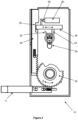
- An example multi-point bolting system on a door 2 is shown in figure 1 .
- the central bolting mechanism that drives the bolts is indicated by 1 in the figure.
- the bolts that move to secure the top and bottom of the door are indicated by 4 and the bolt for securing the opening side of the door is indicated by 5.
- the three bolts are thrown and retracted together by operation of the central bolting mechanism.
- the central bolting mechanism is configured such that one of the bolts, for example the bolt that moves to secure the top of the door, may have its movement blocked by a rotatable deadbolt or latch that engages in a recess in the bolt. Since all three bolts are driven together, by securing one of the bolts against movement, all of the bolts are secured. Rotation of the deadbolt or latch to block movement of the bolts is provided by operation of a key cylinder. With the deadbolt or latch released, the bolts may be thrown or retracted by rotation of handle shown in figure 1 .
- FIG 2 shows the internal components of a bolting mechanism 10 similar to that of figure 1 .
- the bolting mechanism of figure 2 differs from that of figure 1 in that figure 2 comprises a single bolt.
- the arrangement may be readily modified to a multi-point bolting mechanism.
- the bolt 11 is shown in a position extending laterally from the bolting mechanism 10, such as for securing a door at its opening side.
- the bolt 11 can be moved laterally between a thrown position and a retracted position.
- the bolting mechanism comprises a rotor 20 which may be driven by a handle (not shown).
- Rotor 20 has teeth engaging with teeth on the bolt. Rotation of the rotor 20, as shown by arrow B in figure 2 , may retract the bolt.
- Bolting mechanism further comprises internal bolt 30 which also has teeth engaging with rotor 20. Rotation of the rotor 20 may be blocked by internal bolt 30 if sliding deadbolt 40 is positioned to extend into an aperture 32 in the internal bolt 30. The position of the sliding deadbolt 40 is determined by use of a key cylinder 50 or solenoid 60. The sliding deadbolt 40 is configured for lateral translation in the direction shown by arrow A in figure 2 .
- the sliding deadbolt 40 is shown in the thrown position with an end of the sliding deadbolt positioned in the aperture of the internal bolt 30 thereby blocking movement of the internal bolt 30 and also preventing rotation of rotor and movement of bolt 11. Hence, in this position it will not be possible to turn the handle to drive the rotor 20 and the door or leaf remains locked.
- the sliding deadbolt 40 may be retracted by a tang 52 of the key cylinder 50.
- the barrel of the key cylinder may be turned. Clockwise rotation of the key (based on the orientation shown in the figure) will rotate the tang 52 of the key cylinder.
- the bolting mechanism in figure 2 further comprises a solenoid 60.
- the sliding deadbolt 40 may be driven by solenoid 60.
- a solenoid has a core which is moved to extend from, or retract into. the solenoid body depending on whether an electrical voltage or power is applied or turned off.
- Solenoids can be provided with alternative configurations such that they either require power to move the core into the extended position or require power to retract the core into the solenoid body.
- the solenoid shown in figure 2 is unpowered. On application of power the core 62 of the solenoid is retracted into the solenoid body. The retraction of the core 62 retracts the sliding deadbolt 40 from the aperture 32 releasing the internal bolt 30 for movement.
- the solenoid in figure 2 is fitted in the reverse orientation so when powered the tail end of the core is thrown and turning off the power causes the core tail to retract into the solenoid. This movement of the core retracts the sliding deadbolt and releases the internal bolt.
- a problem with the bolting mechanism of figure 1 is that the solenoid core and sliding deadbolt are relatively heavy. This relatively large unsecured (or 'floating') weight means that they could be susceptible to being manipulated from the position in which they prevent movement of the bolt 11 to the position in which the bolt 11 can be retracted. For example, impacting the bolting mechanism or manipulation with a probe could release the sliding deadbolt and could result in forced entry through the door.
- the present invention provides a lock mechanism, comprising: a bolt movable between a thrown position and a retracted position; and a deadbolt assembly comprising: a sliding deadbolt configured to slide between a locked position in which the sliding deadbolt inhibits or prevents retraction of the bolt and an unlocked position in which the bolt is movable, the sliding deadbolt comprising a first anti-thrust cam configured to restrain the sliding deadbolt in the locked position, and a release means or driver arranged such that, when driven, the release means or driver releases the first anti-thrust cam from restraining the sliding deadbolt in the locked position and then slides the deadbolt to the unlocked position.
- the deadbolt assembly may be provided without a release means or driver but is configured to receive, or have fitted later, the release means or driver that releases the first anti-thrust cam and slides the deadbolt to the unlock position.
- the bolt In the thrown position the bolt may be arranged, for example, to extend into a keeper to secure a door or leaf on which the lock mechanism is mounted.
- the bolt In the retracted position the bolt is, at least partly retracted in to the lock mechanism and does not extend into, for example, a keeper, and the door or leaf on which the lock mechanism is mounted may be opened.
- the sliding deadbolt prevents the bolt or bolts from being pushed to a retracted position by a force applied on the end of the bolt or bolts.
- the first anti-thrust cam prevents movement of the sliding deadbolt as may be caused by impacts on, or manipulation of, the bolting mechanism. Such movements may be momentary but could be sufficient to allow the bolt to be released and the door or leaf on which the lock mechanism is mounted may be breached.
- the sliding deadbolt may also be driven by a solenoid having a solenoid core. The relatively large weight of the sliding deadbolt and/or the solenoid core may be sufficient to enable them to be bounced by an impact.
- the first anti-thrust cam provides this anti-bounce feature by providing an additional restraint to the sliding deadbolt such that bounce back of the sliding deadbolt is not possible. Additionally, the first anti-thrust cam is relatively light in weight so is less susceptible to being bounced by impact.
- the sliding deadbolt may be driven by a motor or pneumatic cylinder.
- the release driver may be one or more of the group comprising: a rotatable tang of a key cylinder or rim adaptor; a core of a solenoid; a shaft of a motor; a piston or piston rod of a pneumatic cylinder and a mechanical override.
- the release driver may also be known as the release actuator.
- the first anti-thrust cam may be pivotably coupled to the sliding deadbolt and the sliding deadbolt may comprise an aperture or recess into which the first anti-thrust cam moves or moves further under action of the release driver.
- the first anti-thrust cam may be pivotably coupled to the sliding deadbolt towards an end of the sliding deadbolt that inhibits retraction of the bolt.
- the first anti-thrust cam may be biased such that the distal end of the first anti-thrust cam is pushed out from the aperture when the first anti-thrust cam restrains the sliding deadbolt.
- the first anti-thrust cam may comprise a release surface at an end distal to its pivot and the release driver may comprise a key driven release driver such as a rotatable tang of a key cylinder or rim adaptor.
- a key cylinder may have a barrel, which on insertion of a matching key is able to rotate a tang extending transversely from the middle or rear of the barrel.
- a rim adaptor may be used in combination with a rim cylinder.
- the rim cylinder may have a tailpiece extending from the rear and the tailpiece may locate in a slot in the rim adaptor for driving the rim adaptor.
- the key cylinder or rim adaptor may be configured such that on rotation of the tang the tang pushes against the release surface releasing the first anti-thrust cam.
- the first anti-thrust cam may comprise a receiver and the deadbolt assembly may comprise a detent or catch.
- the detent or catch may be attached to a casing part of the deadbolt assembly or other fixed part of the deadbolt assembly.
- the first anti-thrust cam may be arranged such that when it restrains the sliding deadbolt in the locked position the receiver engages the detent.
- the receiver may comprise a channel or c-shaped recess section and the detent may comprise a pin or stud which locates in the channel or c-shaped recess section when the first anti-thrust cam restrains the sliding deadbolt in the locked position.
- the first anti-thrust cam preferably requires movement for release in a direction orthogonal to the slide direction of the sliding deadbolt. This means that impact in one direction by someone trying to force entry would be unlikely to release both the sliding deadbolt and first anti-thrust cam.
- the light weight of the first anti-thrust cam as mentioned above, further results in making it difficult to bounce the first anti-thrust cam and sliding deadbolt.
- the lock mechanism may further comprise a second anti-thrust cam pivotably coupled to the sliding deadbolt.
- the second anti-thrust cam may be configured for rotational movement in cooperation, that is movement of one causes movement of the other, with the first anti-thrust cam.
- the first anti-thrust cam and second anti-thrust cam may be commonly driven by the release driver.
- the sliding deadbolt may have a slide direction or axis which may correspond to the longitudinal direction of the sliding deadbolt.
- the first anti-thrust cam may be arranged on a first side of the slide direction or axis and the second anti-thrust cam may be arranged on a second side of the slide direction or axis, the second side opposite to the first.
- the first anti-thrust cam may be arranged to be, in some positions, at least partly below the slide direction of the sliding deadbolt, and the second anti-thrust member may be arranged at least partly above the slide direction of the sliding deadbolt.
- the release driver for example, when it is an electrical release driver such as a solenoid or motor, or a pneumatic release driver such as a pneumatic cylinder, may be arranged such that when driven it rotates the second anti-thrust cam causing rotation of the first anti-thrust cam releasing the first anti-thrust cam from restraining the sliding deadbolt in the locked position. Further driving of the release driver may cause sliding of the deadbolt to the unlocked position.
- the first anti-thrust cam and second anti-thrust cam may comprise intermeshing teeth to transfer rotational movement between the first anti-thrust cam and second anti-thrust cam.
- Alternative features to intermeshing teeth may be provided to transfer to rotational movement between the first and second anti-thrust cams.
- the cams could push against each, the cams may act as levers against each other, or the cams may be coupled to each other by a belt of chain. Other alternatives are also possible.
- the sliding deadbolt may comprise a drive fork, for example which extends substantially transversely, or partly transversely, to the slide direction of the deadbolt.
- the second anti-thrust cam may be arranged between the prongs of the drive fork.
- the release driver may be a solenoid, pneumatic cylinder or motor, and the second anti-thrust cam may be arranged to be driven by the solenoid, pneumatic cylinder or motor.
- the lock mechanism may comprise two release drivers: the first release driver, which may be the tang of a key cylinder or rim adaptor, may operate on the first anti-thrust cam; and the second release driver may be the solenoid, pneumatic cylinder or motor and may operate on the second anti-thrust cam.
- the release drivers may be arranged such that, when one of the release drivers is driven, the driven release driver releases the first anti-thrust cam from restraining the sliding deadbolt in the locked position and slides the deadbolt to the unlocked position.
- the lock mechanism may further comprise an additional release driver which is the mechanical override.
- the mechanical override may comprise a projection, which may for example be known as a nose projection, extending transversely from the second anti-thrust cam and arranged to be acted on for rotational movement of the second anti-thrust cam to release the sliding deadbolt.
- the bolt, or a slider of the bolt may be arranged to push against the projection, or nose projection, or to simply push against the second anti-thrust cam, to rotate the second anti-thrust cam and release the sliding deadbolt as the bolt is moved to the retracted position.
- the second anti-thrust cam may be pivoted towards an end proximal to the first anti-thrust cam.
- the release driver may comprise a motor, for example having a threaded shaft or threaded drive shaft.
- the threaded shaft or threaded drive shaft may be configured such that rotation of the threaded shaft or threaded drive shaft is configured to drive the second anti-thrust cam and the sliding deadbolt for release of the sliding deadbolt.
- the deadbolt assembly may further comprise a coupler and a carriage or carriage block.
- the carriage may receive the threaded drive shaft, such as in a threaded hole, and may be configured such that on rotation of the threaded drive shaft the carriage moves linearly.
- the coupler may be coupled between the second anti-thrust cam and the carriage for driving the second anti-thrust cam and sliding deadbolt when the threaded drive shaft is driven.
- the carriage may be configured to move between a first position and a second position. In moving to the first position the carriage may pull on the coupler such that the second anti-thrust cam is rotated to release the sliding deadbolt.
- the coupler may be configured to provide lost-motion such that in the second position the coupler can move relative to the carriage when the second anti-thrust cam is rotated by means other than the motor, such as by a mechanical override or by the first anti-thrust cam.
- the release driver may comprise a pneumatic cylinder.
- the pneumatic cylinder may have a piston rod which moves between extended and retracted positions as the pneumatic pressure.
- the piston may extended when compressed air is applied.
- the piston rod may be connected to a coupler which is coupled to the second anti-thrust cam for driving the second anti-thrust cam and sliding deadbolt. Operation of the pneumatic cylinder is similar to that of the motor or solenoid.
- the release driver may comprise a key cylinder or rim adaptor and the sliding deadbolt may comprise a release surface configured to be acted on by the rotatable tang of the key cylinder or rim adaptor such that on rotation of the tang, the tang releases the first anti-thrust cam, and pushes against the release surface of the sliding deadbolt to retract the sliding deadbolt and release the bolt for movement.
- the sliding deadbolt may comprise a side arm which may project transversely from the slide direction of the sliding deadbolt and the release surface may be provided on the sidearm.
- the drive fork of the sliding deadbolt may project transversely to the slide direction of the sliding deadbolt.
- the lock mechanism may further comprise a solenoid having a core connected to a drive rod.
- the drive rod may be coupled to the second anti-thrust member and between the prongs of the drive fork.
- the drive rod may be configured to drive the second anti-thrust member and the sliding deadbolt for release of the sliding deadbolt. Similar arrangements may be used if a motor or pneumatic cylinder is used instead of a solenoid.
- a coupler driven by the motor or pneumatic cylinder may couple between the prongs of the drive fork to drive the second anti-thrust member and the sliding deadbolt for release of the sliding deadbolt.
- the lock mechanism may further comprise front and back plates, such as of a casing, between which the sliding deadbolt may be configured to move.
- the sliding deadbolt may comprise guides arranged to move in slots of the front and back plates to guide movement of the sliding deadbolt between the locked position and the unlocked position.
- the front and back plates may further comprise apertures through which a key cylinder or rim adaptor is mounted.
- the bolt may comprise a recess, which in the retracted position, may receive an end of the sliding deadbolt to inhibit retraction of the bolt.
- the lock mechanism may comprise a key cylinder or rim adaptor, solenoid, pneumatic cylinder or motor, or mechanical override.
- the lock mechanism may comprise one, two or all of these as the release driver.
- the lock mechanism may comprise one or other of a key cylinder and rim adaptor, along with one of a solenoid, pneumatic cylinder and motor, and optionally may include a mechanical override.
- the present invention further provides a multi-point bolting mechanism comprising the lock mechanism described above, and further comprising one or more additional bolts arranged to be driven together with the bolt of the lock mechanism.
- the present invention further provides a deadbolt assembly comprising: a sliding deadbolt configured to slide between a locked position in which the sliding deadbolt inhibits retraction of a bolt and an unlocked position, the sliding deadbolt comprising a first anti-thrust cam configured to restrain the sliding deadbolt in the locked position, and a release driver arranged such that, when driven, the release driver releases the first anti-thrust cam from restraining the sliding deadbolt in the locked position and slides the deadbolt to the unlocked position.
- the deadbolt assembly may further comprise a second anti-thrust cam pivotably coupled to the sliding deadbolt and configured for rotational movement in cooperation with the first anti-thrust cam.
- the deadbolt assembly may further comprise any of the features set out above regarding the deadbolt assembly which forms part of the lock mechanism.
- the present invention further provides a bolting mechanism comprising the deadbolt assembly set out above.
- a deadbolt assembly comprising: a sliding deadbolt configured to slide between a locked position in which the sliding deadbolt inhibits retraction of a bolt and an unlocked position.
- the deadbolt assembly may be configured to receive a first release driver, wherein the first release driver may be driven by a key, such as a key cylinder or rim adaptor.
- the deadbolt assembly may further comprise a second release driver, wherein the second release driver may be a mechanical override, electrical release driver such as a solenoid or motor, or pneumatic release driver such as pneumatic cylinder.
- the sliding deadbolt may further comprise: a first anti-thrust cam configured to restrain the sliding deadbolt in the locked position, the first anti-thrust cam configured for driving by the first release driver; and a second anti-thrust cam coupled to the sliding deadbolt and configured for rotational movement in cooperation or common with the first anti-thrust cam.
- the second anti-thrust cam may be configured for driving by the second release driver.
- the release drivers may be arranged such that, when one of the release drivers is driven, the driven release driver releases the first anti-thrust cam from restraining the sliding deadbolt in the locked position and slides the deadbolt to the unlocked position.
- the present invention also provides a door or leaf comprising mounted thereto the lock mechanism, the multi-point bolting mechanism, the deadbolt assembly or the bolting mechanism set out above.
- Figure 3 is a plan diagram of a mechanism of a multi-point bolting mechanism according to an embodiment of the present invention.
- the bolting mechanism is similar to the arrangement of figure 2 in that it has a laterally movable bolt which is driven by a rotor 20.
- the laterally movable bolt is indicated by 11a.
- a second rotor 21 is provided which allows the mechanism to be mounted on left-handed or right-handed opening doors. That is, either the first rotor 20 or second rotor 21 may be connected by a spindle for driving by handle. The selection of which rotor is driven by the handle will be based on the direction required for rotation of the handle.
- the bolting mechanism of figure 3 also includes two other bolts 11b, 11c, which are similar to bolts 4 in figure 1 for securing the top and bottom of a door or leaf.
- the bolts 11b and 11c in figure 3 may be relatively longer than shown in the figure to reach the top and bottom of the door or have connecting rods to extend to fit the length of the door.
- the bolt 11b is also similar to internal bolt 30 of figure 2 .
- Bolt 11a is provided between rotors 20 and 21 and transfers rotation of one of the rotors to rotate the other rotor. In doing so the bolt 11a is translated to retract the bolt or the throw the bolt.
- Bolt 11c is driven by rotor 21 and bolt 11b is driven by rotor 20.
- One of the bolts of the multi-point bolting mechanism may be secured by a sliding deadbolt 110 of deadbolt assembly 100.
- the sliding deadbolt is thrown to be located in cut-out or recess 110a of bolt 11b.
- the sliding deadbolt may act to restrain other of the bolts of a multi-point bolting mechanism or on the bolt of a single bolt lock mechanism.
- the multi-point bolting mechanism of figure 3 is provided as an example of a bolting mechanism which the deadbolt assembly may be used with. Mechanisms other than that of figure 3 may be provided which include a bolt that is restrained by the deadbolt assembly of the present invention.
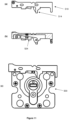
- Figures 4 and 5 show in more detail the deadbolt assembly 100.
- Figure 4 is a plan view of the front of the deadbolt assembly.
- Figure 5 is a perspective view of the deadbolt assembly.
- the sliding deadbolt 110 can be seen on the left of figures 4 and 5 .
- Also shown in figures 4 and 5 as part of the deadbolt assembly are solenoid 200 and key cylinder 210.
- Figure 6a shows a view of the internal components of the deadbolt assembly 100, that is with a front plate 115 of casing removed.
- Figures 6b and 6c are front plan and end plan views of the sliding deadbolt 110 assembled to include anti-thrust cams.
- Figure 6d is a cross-sectional view of the sliding deadbolt 110 taken along the line A-A of figure 6b .
- sliding deadbolt 110 is elongate and in operation is configured to slide in its elongate direction.
- the sliding deadbolt 110 has a first end 112, which may also be known as the head end, is shaped for location in the recess or cut-out 110a in bolt 11b.
- this head end 112 is shown to have a rectangular shape. Other shapes are possible but the shape should be such that the bolt can be restrained by the sliding deadbolt. For example, if a force is applied to the end of bolt 11b then the sliding deadbolt 110 prevents the bolt 11b being pushed in or retracted.
- a rectangular shape or shape which has parallel sides which in use will be orthogonal to the direction of movement of the bolt is preferred.
- Sliding deadbolt 110 further comprises a release feature which in the embodiment of figure 6a-6d is a release projection 114.
- the release projection 114 may also be known as a side arm.
- the side arm extends from the elongate direction of the sliding deadbolt 110, such as transversely or orthogonally to the sliding deadbolt.
- the sliding deadbolt 110 further comprises guides 118 which guide movement of the sliding deadbolt in the elongate direction.
- Figures 6a and 6c shown two such guides 118 which project from the side surface of the sliding deadbolt 110.
- the guides shown are elongate. Other shapes and numbers of guides are possible.
- One or more guides, preferably two guides, are provided on each side of the sliding deadbolt.
- the guides 118 shown in figures 6a and 6c locate in a slot 120 in front plate 115 as shown in figures 4 and 5 . Further guides (not shown) locate in slot in rear plate 116 of the casing.
- the slot guides the movement direction, that is the sliding direction, of the sliding deadbolt plate 110. The extent of sliding may be limited by the length of the slot 120.
- Sliding deadbolt further comprises a drive fork 122 projecting from the elongate direction of the sliding deadbolt 110, as shown in figures 6b and 6c .
- the drive fork 122 projects transversely or orthogonally from the elongate direction or slide direction of the sliding deadbolt 110.
- the fork is for actuation of the sliding deadbolt 110 by solenoid 210.
- the release projection or side arm 114 of the sliding deadbolt 110 has a drive face and a cut-out 114a at the rear side, that is the opposite side to the drive face.
- the cut-out 114a is curved as shown in figures 6a and 6c .
- the cut-out 114a is provided such that the side arm does not hit mounting feature or boss 146 when the sliding deadbolt is retracted.
- Mounting feature or boss may be a hole for receiving a fixing for mounting the deadbolt assembly 100 in the lock mechanism, or may alternatively be a boss or cylinder which also provides mounting of the deadbolt assembly 100 in the lock mechanism.
- Figure 6d shows first and second anti-thrust cams 124, 126.
- First anti-thrust cam 124 may be considered to have a shape resembling the head of a duck.
- First anti-thrust cam is at least partly located in a recess 128 in the sliding deadbolt, as shown in figure 6d .
- First anti-thrust cam may also be considered to be a rod or small bar.
- the first anti-thrust cam is pivoted towards one end at pivot 124a.
- the first anti-thrust cam 124 is biased by coiled spring 130 to pivot the distal end of the cam out of the recess 128 of the sliding deadbolt 110.
- the spring may be a small or low gauge spring.
- biasing arrangements are possible such as a lever spring or differently located coiled spring.
- the ends of the spring respectively locate in a hole in the anti-thrust cam and a hole in the sliding deadbolt.
- the end of the first anti-thrust cam 124 distal to the pivot 124a comprises a receiver 132 such as a socket or channel, which may have a circular or part circular cross-section and is for locating on pin or stud 136 as will be explained later.
- the end of the first anti-thrust cam 124 further comprises a drive face 134 which forms part of the duck's head shape, that is, it extends obliquely from the bar or rod direction of the anti-thrust cam.
- Figure 6d also shows second anti-thrust cam 126.
- the second anti-thrust cam extends towards the drive fork 122.
- the second anti-thrust cam 126 extends between the two prongs of the drive fork 122.
- Second anti-thrust cam is pivoted at one end close to the first anti-thrust cam 124.
- Figure 6d shows the pivot as 126a.
- the first and second anti-thrust cams have teeth which intermesh to transfer rotational movement of one anti-thrust cam to the other. Intermeshing teeth are one embodiment, but other embodiments may provide alternatives for transferring rotational such as lever or camming surfaces or by belt or chain.
- the second anti-thrust cam 126 is shorter than the first anti-thrust cam 124.
- the second anti-thrust cam 126 comprises a projection 138, which may be known as the nose projection, which extends transversely from the length direction of the second anti-thrust cam.
- the nose projection 138 is arranged to be acted on for mechanical override of the sliding deadbolt as will be described later.
- Figures 4 and 5 show solenoid 200.
- the second anti-thrust cam 126 is coupled to the core of the solenoid by 200 by connecting rod 140.
- the connecting rod 140 and second anti-thrust cam 126 are themselves coupled together by pin 142 located through holes at either side of the end of the connecting rod and through a slot in the second anti-thrust cam 126.
- the slot allows for some movement transverse to the direction of movement of the solenoid core as the second anti-thrust cam 126 rotates.
- Connecting rod 140 comprises first and second shoulders.
- the connecting rod 140 extends between the prongs of the drive fork 122, with the first shoulder 140a at the solenoid side of the drive fork and the second shoulder 140b beyond the drive fork 122.
- the space between the prongs of the drive fork accommodates the part of the connecting rod that is between the shoulders.
- the shoulders are wider than the space between the prongs of the drive fork so as to limit movement of the connecting rod with respect to the drive fork and also allow second anti-thrust cam 126 and connecting rod 140 to move a limited amount without moving the drive fork and sliding deadbolt 110.
- the end of the connecting rod distal to the solenoid 200 comprises a slot in which the second anti-thrust cam 126 resides. The slot extends from the end of the connecting rod to the first shoulder 140a.
- the sliding deadbolt 110 is biased to the thrown position for engagement in the bolt.
- the bias is provided by coiled spring 144 which pushes between the solenoid mounting and the drive fork 122.
- Other means of bias to the sliding deadbolt 110 may be provided and may be arranged at places other than between the drive fork 122 and solenoid mounting.
- Figures 4, 5 and 6a show a key cylinder 210 mounted through apertures in the front plate 115 and rear plate of the casing.
- the key cylinder may be replaced by a rim adaptor. Both a key cylinder and a rim adaptor have a rotatable tang.
- a key cylinder comprises a barrel which on receipt of a matching key allows rotation of the barrel and tang.
- a rim adaptor may be used in combination with a rim cylinder which has a rotatable tailpiece extending from its rear. The tailpiece may be inserted in to a slot in the rim adaptor for driving the tang of the rim adaptor in the same way as the key cylinder.
- rim adaptor or key cylinder The choice of whether to use a rim adaptor or key cylinder will depend on the desired placement and geometry at which the key is to be inserted. A rim adaptor and rim cylinder will place the key insert spaced away from the deadlock assembly.
- the rim adaptor or key cylinder may be fixed to the deadlock assembly by a screw or fixing through the casing such as through a hole 115a in side face of the casing.
- a key cylinder 210 may instead be a rim adaptor.
- a key cylinder is referred to this may be replaced with a rim adaptor.
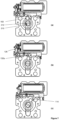
- FIG 7a shows the deadbolt assembly in cross-section taken through a plane coincident with line A-A of figure 6b .
- Figure 7a shows key cylinder 210 in which plug or barrel has been rotated relative to the position shown in figure 6a .
- the key insert 212 of the barrel or plug is shown in the horizontal position and drive tang 160 of the key cylinder is not visible because it is in the downward vertical position and is hidden by the lobe of the key cylinder body.
- the tang 160 has been rotated almost 180 degrees clockwise and is almost at the vertically upward position.
- the key insert 212 of the key cylinder has also been rotated by almost 180 degrees and it is this rotation that has moved the tang 160.
- the tang 160 has just come into contact with the drive face 134 of the first anti-thrust cam 124 but has not yet caused the anti-thrust cam 124 to move.
- the sliding deadbolt 110 is maintained in the thrown position with receiver 132 of the anti-thrust cam 124 holding pin or stud 136 to prevent bouncing of the sliding deadbolt 110 or solenoid core.
- the receiver 132 of the first anti-thrust cam 124 surrounds around half to two-thirds of the pin 136 as shown in figure 7a .
- the receiver is not quite clear of the pin but because the edge 132a of the channel of the receiver has passed the midpoint of the pin 136, the edge of the receiver channel will be pulled around and over the pin as the sliding deadbolt 110 is retracted. It is expected that parts may wear. As this happens the anti-thrust cam may not lift as high. However, because it is only required that the edge 132a of the receiver channel is moved beyond halfway above the pin 136, the retraction of the sliding deadbolt will lift the first anti-thrust cam 124 clear of the pin.
- Figures 7a to 7c also show operation of the second anti-thrust cam 126.
- the solenoid core is extended and the second anti-thrust cam is in the near vertical position.
- the intermeshing teeth of the first and second anti-thrust cams means that rotation of one of the anti-thrust cams results in rotation of the other of the anti-thrust cams.
- the first anti-thrust cam 124 is rotated during the retraction of the sliding deadbolt 110 by the tang of the key cylinder.
- the second anti-thrust cam 126 will also be rotated.
- the second anti-thrust cam 126 will be rotated in the opposite direction to the first anti-thrust cam 124.
- the solenoid 200 may be configured to retract the solenoid core from an extended position either on application of a voltage or removal of a voltage. In the present case it is preferred that a voltage is applied to retract the solenoid core. This provides a fail secure arrangement such that when there is no power the deadbolt remains thrown and the bolting mechanism is secured.
- the solenoid core has been retracted and has pulled on connecting rod 140. The connecting rod is coupled to the second anti-thrust cam 126 at pin 142 and the retraction pulls the distal end of the second anti-thrust cam 126 causing it to rotate about its pivot 126a.
- the intermeshing teeth with the first anti-thrust cam 124 causes the first anti-thrust cam 124 to also rotate but in the opposite direction to the second anti-thrust cam 126. Hence, the distal end of the first anti-thrust cam is lifted upwards releasing the receiver 132 from the pin 136.
- further operation of the solenoid such as by supplying power causes the second shoulder 140b of connecting rod to come into contact with drive fork 122 of the sliding deadbolt 110 and pulls the drive fork towards the solenoid.
- the whole of the sliding deadbolt 110 is retracted. This is shown in figure 7c where the sliding deadbolt can be seen to have moved to the right.
- the solenoid 200 first moves the anti-thrust cams 124, 126 before retracting the sliding deadbolt 110.
- the deadbolt assembly 100 which restrains movement of a bolt such as for a multi-point bolting mechanism may comprise a mechanical override as we will now describe with reference to figures 3 and 8a-8c .
- a mechanical override as we will now describe with reference to figures 3 and 8a-8c .
- the mechanism of figure 3 is a multi-point bolting mechanism comprising three bolts which are driven by two teethed rotors.
- the mechanism may be driven by a handle coupled to rotor 21 by a spindle.
- a spring assembly 23 which provides a bias to throw the three bolts outward when the handle is released. The bias pushes the linear toothed element of spring assembly 23 upwards, such as to the position shown in the figure, which causes rotor 21 to rotate anti-clockwise and throw the three bolts 11a, 11b and 11c.
- Each of the bolts 11a, 11b and 11c is provided with a slider, which are respectively denoted by 11as, 11bs and 11cs.
- the sliders overlie their respective bolts.
- the slider 11bs for the top bolt 11b has teeth which engage with the teeth of upper rotor 20.
- the slider 11 as for the central bolt 11a which moves laterally, has teeth which engage with the teeth of both upper rotor 20 and lower rotor 21.
- the slider 11cs for the bottom bolt 11c has teeth which engage with the teeth of lower rotor 21.
- the slider 11as of central bolt is shown in figure 3 as having two slots.
- the sliders and two rotors 20 and 21 may be replaced by an arrangement of four rotors as described in GB 2520666 by the current applicant.
- the rotors are arranged as two pairs, with the two rotors of each pair rotating on a common axis.
- a slider is retained on the central bolt between the rotors. Lost motion is provided between the two rotors in a pair.
- aspects of the arrangement disclosed in GB 2520666 and figure 3 of the current application may be combined.
- the multi-point bolting mechanism of figure 3 is provided as an illustration of an application of the deadbolt assembly and the deadbolt assembly may be applied to numerous other lock mechanisms comprising a bolt.
- the deadbolt assembly is not limited to operation on the upper bolt of a multi-point bolting mechanism but may be applied to any of the other bolts, and multiple deadlock assemblies may be applied.
- deadlock assemblies may be used on the upper and lower bolts.
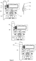
- FIGs 3 and 8a show the sliding deadbolt 110 in the thrown position extending into recess 110a in bolt 11b. Slider 11bs for bolt 11b is also shown.
- the right hand side of figure 8a shows the different features schematically.
- the end of the sliding deadbolt 110 is indicated by a solid line forming three sides of a rectangle.
- the recess 110a in the bolt 11b is also shown by a solid line. It can be seen that the recess is rectangular.
- the slider 11bs also has a recess 110b which is shown by dashed line in the right hand side figure of figure 8a .
- the recess 110b in slider 11bs has a lower end which is rectangular and an upper end which has a sloping edge.
- projection 138, also known as nose projection, of the second anti-thrust cam 126 is also shown in figure 8a. In the position shown in figure 8a the bolt 11b cannot be driven back by a force applied to the end of the bolt because the upper edge of the recess 110a of the bolt will hit the end of the sliding deadbolt 110.
- Figures 8b and 8c show how the sliding deadbolt 110 is mechanically overridden to allow the bolt 11b to be retracted.
- the slider 11bs has been moved downwards. This will have been caused by rotation of the handle as described in relation to figure 3 on the preceding pages.
- the sloping edge of the recess 110b of the slider 11bs is now pushing against the nose projection 138 of the sliding deadbolt 110.
- This rotates the second anti-thrust cam 126 to the position shown in figure 7b .
- the intermeshing teeth of the first and second anti-thrust cams results in rotation of the first anti-thrust cam 124 such that the receiver 132 is lifted substantially clear of pin 136 as described above in relation to figure 7b .
- the lifting of the distal end of the first anti-thrust cam 124 can also be seen by comparing figure 8b to 8a .
- the sliding deadbolt can now be retracted.
- FIG 8b The slider 11bs of the bolt has been moved downwards further such that the slope of the recess 110b has been moved downwards beyond the projection 138.
- the slider pushes the projection further towards the solenoid and thereby also pushes drive fork 122 towards the solenoid to retract the sliding deadbolt 110.
- the sliding deadbolt is retracted from the recess 110a in the bolt 11b and the bolt 11b can now be retracted. This will be achieved by further turning of handle and rotors.
- the sliding deadbolt 110 can be released and retracted using three different actions, namely by action of a tang of a key cylinder or rim adaptor; by action of the solenoid; or by mechanical override.
- the sliding deadbolt and its anti-thrust cams prevent the solenoid and sliding deadbolt from being manipulated, perhaps only even momentarily, to the retracted positions.
- the solenoid is configured such that power is applied for retraction and maintaining in the retracted position the sliding deadbolt 110. This would mean that the sliding deadbolt could be unpowered for most of the time because the sliding deadbolt would be thrown for most of the time. This would save power and provide a fail-secure mode in which during a loss of power the sliding deadbolt remains thrown and the bolting mechanism is secured. In such a configuration retraction of the sliding deadbolt by the key cylinder or by the mechanical override would not be impeded by the solenoid.
- the solenoid configuration can be suitably selected for the desired mode during a loss of power. For example, if free-escape from a building is desired in the event of loss of power, the fail-safe mode would be selected. In the arrangement in which the solenoid is powered in the thrown position, this may provide a resistance, but does not prevent retraction of the sliding deadbolt by the key cylinder or mechanical override.
- the solenoid is flipped around such that the spring 144 biases the solenoid core at the other end of the assembly.
- the solenoid could be used to throw and retract the sliding deadbolt and is only powered during the actions of throwing or retracting the sliding deadbolt. In such a case the sliding deadbolt 110 would be maintained in the thrown position by the first anti-thrust cam's receiver 132 and pin 136.
- the first anti-thrust cam 124 moves under bias of spring 130 to cause it to rotate and push the distal end out of recess 128.
- the receiver 132 will drop on to pin 136. Once this has happened the first anti-thrust cam is in position to prevent bouncing of the sliding deadbolt. Since the second anti-thrust cam 126 has teeth in engagement with the first anti-thrust cam 124, rotation of the first anti-thrust cam will result in rotation of the second anti-thrust cam 126 and both anti-thrust cams will be returned to the positions shown in figure 7a .
- the process of throwing the sliding deadbolt is similar whether by action of the solenoid or release of the mechanical override.
- the solenoid once the solenoid core has been released, such as power turned off, the spring 144 will push the sliding deadbolt to the thrown position and the anti-thrust cams will move as described in the preceding paragraph.
- the mechanical override will be released when the bolt 11b moves back upwards to the thrown position as shown in figure 8a and the sliding deadbolt 110 is biased by spring 144 to push into recess of 110a of bolt.
- the deadbolt assembly comprises three means for operating the sliding deadbolt 110.
- the key cylinder provides conventional operation by a user with a key matching the key cylinder who is at the location.
- the solenoid provides operation by means of an access control system.
- Such a system may have various implementations and modes of operations but release of the sliding deadbolt is caused by an electrical signal being received at a controller at the lock mechanism.
- a user may be provided with an electronic swipe card which on presentation at a sensor at the door provides the electronic signal for release.
- the electronic signal may be provided remotely such as from a control room or site office, to retract the sliding deadbolt between, for example, working hours of a day or week.
- Such a signal may be provided wireless or by wired means.
- the mechanical override advantageously may provide emergency egress from a building.
- a door on which the lock mechanism is mounted may provide an exit for persons from a building in an emergency.
- Turning of the handle on the inside of the door operates the mechanical override and allows the bolts to be retracted. Without the mechanical override it would be necessary for the person to have the key matching the key cylinder. Operations by the key cylinder could be retained for opening of the door from the outside of the building.
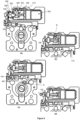
- Figures 9 and 10 show alternative embodiments of the present invention.
- the embodiment of figures 4-8 comprises a solenoid 200 as a release driver or drive actuator for driving the second anti-thrust cam such as may be required by an access control system.
- the solenoid is replaced by a motor 300, whereas in the embodiment of figure 10 the solenoid is replaced by a pneumatic cylinder 400.
- FIG 9a motor 900 which takes the place of solenoid 200.
- the motor has a threaded drive shaft 310 which extends from the motor body.
- the threaded drive shaft 310 is rotated by the motor when the motor is powered, for example in clockwise and anti-clockwise directions.
- the threaded drive shaft extends into carriage 320 which has a threaded hole.
- the threaded drive shaft extends into threaded hole and acts like a lead screw such that as the drive shaft is rotated by the motor the screw threads on the shaft drive the carriage 320 linearly forwards or backwards depending on the direction of rotation of the shaft 310.
- the carriage is prevented from rotating by having part, such as a pin, extending into a guide slot in guide 322.
- the guide slot allows linear movement of the pin of the carriage.
- a coupler 330 which couples movement of the carriage 320 to the second anti-thrust cam 126.
- the coupler has a narrow portion or rod portion 332 along which the carriage can translate.
- the carriage has a hole through which the narrow portion or rod portion 332 of the coupler extends.
- One end of the coupler 334 couples to the second anti-thrust cam 126 and has a stop to limit translation of the carriage along the coupler.
- the stop is a wider portion.
- the opposite end of the coupler 330 has a head 336 which is also wider stopping translation of the carriage.
- Figure 9a shows the sliding deadbolt thrown in the position which would secure the bolt similar to as shown in figure 8a .
- the motor has operated causing rotation of the second anti-thrust cam 126 and retraction of the sliding deadbolt 110.
- the operation of the motor has turned the drive shaft 310 causing the carriage 320 to move towards the motor body.
- Arrow R in figure 9b indicates the carriage 320 has moved.
- the translation of the carriage 320 has pulled on the head 336 of the guide 330 which in turn has pulled the guide towards the motor.
- the movement of the guide causes the second anti-thrust cam to rotate in the same was as when driven by the solenoid as described above.
- the rotation of the second anti-thrust cam 126 causes the first anti-thrust cam 124 to rotate releasing the sliding deadbolt 110 which is then retracted.
- the movement of the first anti-thrust cam 124 and sliding deadbolt 110 is the same as described for the solenoid actuation.
- the motor is first powered to drive the threaded shaft in the opposite direction to move the carriage 320 back to the starting position shown in figure 9a .
- the coupler 330 is then free to return back to its starting position shown in figure 9a under action of spring 338.
- the spring 338 pushes against the sliding deadbolt, such as against upstanding prongs 122, which causes the sliding deadbolt 110, second anti-thrust cam 126 and coupler 330 to return to their thrown or secure positions shown in figure 9a .
- carriage having a hole along which the coupler moves other arrangements are possible such as coupler having a channel or rail along which carriage is arranged to move.
- Figure 9c shows that operation of the key override, as previously described, is unaffected by the change from solenoid to motor. Similar to the steps shown in figures 7a-7c the tang 160 of the key cylinder has been rotated releasing first anti-thrust cam 124 and retracting the sliding deadbolt 110. In figure 9c the positions of the tang 160 of the key cylinder, first anti-thrust cam 124 and the sliding deadbolt 110 are the same as shown in figure 7c . The rotation of the tang 160 of the key cylinder is indicated by arrow S. In figure 9c the rotation of the first anti-thrust cam has caused the second anti-thrust cam 126 to also rotate pushing coupler 330 towards the motor.
- the motion of the coupler is not prevented by the carriage because the coupler can slide with respect to the carriage. In this regard it may be considered that there is lost motion between the carriage 320 and coupler. Hence, the position of the carriage, which is set by the motor, does not prevent actuation of the lock mechanism by the key cylinder.
- Figure 9d shows operation of the mechanical override similar to that shown in figures 8a-8c .
- part of the bolt pushes against projection 138 on the second anti-thrust cam 126 causing the second anti-thrust cam to rotate, releasing the first anti-thrust cam 124 and retracting the sliding deadbolt.
- the embodiment of figure 9 operates in the same way, as shown in figure 9d , except that a projection 138 on the second anti-thrust cam is not shown.
- the second anti-thrust cam may or may not be provided with a projection but if it is not provided adaptation of the part of the bolt that pushes against it may be required.
- the operation of the mechanical override is the same as for figure 7 .
- a mechanical override may, for example, be a result of turning an internal lever handle such as for emergence override. This could be for example by rotation of a handle attached to rotor 21 of figure 3 .
- the handle may provide emergency egress.
- a motor instead of a solenoid may be desirable for low power applications. If a solenoid is used in a configuration in which it only needs to be powered at the time access is required, on average the solenoid is required to be powered for six seconds, whereas the motor only requires power for one second. Furthermore, the power consumption in general of the solenoid may be more than that of the motor. Hence, a motor may be preferable for remote sites where mains or grid power is unavailable and the lock mechanism is powered by battery.
- the pneumatic cylinder 400 comprises an input for receiving compressed air at arrow U.
- the pneumatic cylinder comprises a piston rod 410 which is extended or driven when compressed air is applied to the cylinder.
- the piston rod is connected to a drive bar 420 which in turn is coupled to a coupler 430 of the second anti-thrust cam.
- the pneumatic cylinder is arranged such that on application of compressed air the piston rod extends in a direction away from the second anti-thrust cam.
- figures 10a and 10b do not shown all of the features of the anti-thrust and anti-bounce mechanisms but mechanisms corresponding to those in the preceding figures may nevertheless be included.
- FIG 10a the sliding deadbolt is shown in the thrown position and the first and second anti-thrust cams are positioned to prevent movement of the sliding deadbolt.
- compressed air is applied to the pneumatic cylinder 400 which has caused the piston rod 410 to extend further from the cylinder as indicated by arrow U in figure 10b .
- the piston rod pulls drive bar 420 in a direction away from second anti-thrust cam.
- the drive bar is coupled to coupler 430 which causes second anti-thrust cam to rotate releasing and retracting the sliding deadbolt in similar way to the solenoid and motor described herein.
- an internal spring to the pneumatic cylinder 400 retracts the piston rod returning the sliding deadbolt and first and second anti-thrust cams to the secured or thrown position shown in figure 10a .
- a pneumatic cylinder may be used where compressed air can be readily supplied or electrical operation is undesirable.
- FIGS 11a-c show an alternative embodiment of deadbolt assembly.
- This embodiment is operated by a key cylinder or rim adaptor alone.
- This embodiment is similar to the preceding embodiments but does not include the second anti-thrust cam 126. Hence, retraction of the sliding deadbolt is by the key cylinder only. Similar to the preceding embodiments, a rim adaptor may be used in place of the key cylinder.
- Figure 11c shows deadbolt assembly 500 comprising key cylinder and sliding deadbolt 510. Sliding deadbolt is shown in more detail in figures 11a and 11b.
- Figure 11b shows the sliding deadbolt cut through in cross-section in the same plane as the cross-section of figure 6d .
- first anti-thrust cam 524 of this embodiment can be seen clearly and is similar to the first anti-thrust cam 124 of preceding embodiments.
- the first anti-thrust cam 524 is pivoted at one end and biased by spring in a similar manner to the preceding embodiments. It also comprises a receiver, which may be a channel, which locates around a pin or stud configured between front and back plates of the casing.
- the sliding deadbolt 510 comprises release projection 514 which is described as side-arm in the above embodiments.
- the tang of the key cylinder is rotated clockwise. At close to 180 degrees of rotation the tang pushes against the drive face of the anti-thrust cam 524 lifting/rotating the cam such that the pin is released from the receiver. Further rotation of the tang of the key cylinder pushes against the side arm 514 of the sliding deadbolt 510 to retract the sliding deadbolt. To throw the sliding deadbolt 510 the tang of the key cylinder is returned to bring it into line with the lobe of the key cylinder body.
- a bias provided on the sliding deadbolt pushes it into the thrown position.
- the bias is provided differently and may be provided by a spring hidden inside the sliding deadbolt which pushes against a feature of the casing. Other biasing arrangements are also possible.
- first and second anti-thrust cams may be instead be arranged without teeth but to drive each other by lever action or the use of a belt or chain.
- the solenoid may be replaced with a motor such as a worm drive motor providing linear movement in a similar manner to the solenoid.
- variations in the actual shapes of the parts such as the sliding deadbolt, anti-thrust cams, rotors, sliders and bolt may be made without diverging from the general scope of the present invention.
Abstract
Description
- The present invention relates to a deadbolt assembly for controlling access, for example, to a room or building. More particularly the invention relates to a deadbolt assembly, which forms part of a lock mechanism, in which a sliding deadbolt constrains movement of a bolt, and an anti-thrust cam prevents bouncing or manipulation of the sliding deadbolt.
- A prior art bolting mechanism incorporating a deadbolt is disclosed in
GB 2413822 door 2 is shown infigure 1 . The central bolting mechanism that drives the bolts is indicated by 1 in the figure. The bolts that move to secure the top and bottom of the door are indicated by 4 and the bolt for securing the opening side of the door is indicated by 5. The three bolts are thrown and retracted together by operation of the central bolting mechanism. The central bolting mechanism is configured such that one of the bolts, for example the bolt that moves to secure the top of the door, may have its movement blocked by a rotatable deadbolt or latch that engages in a recess in the bolt. Since all three bolts are driven together, by securing one of the bolts against movement, all of the bolts are secured. Rotation of the deadbolt or latch to block movement of the bolts is provided by operation of a key cylinder. With the deadbolt or latch released, the bolts may be thrown or retracted by rotation of handle shown infigure 1 . -
Figure 2 shows the internal components of abolting mechanism 10 similar to that offigure 1 . The bolting mechanism offigure 2 differs from that offigure 1 in thatfigure 2 comprises a single bolt. However, the arrangement may be readily modified to a multi-point bolting mechanism. Infigure 2 , thebolt 11 is shown in a position extending laterally from thebolting mechanism 10, such as for securing a door at its opening side. Thebolt 11 can be moved laterally between a thrown position and a retracted position. The bolting mechanism comprises arotor 20 which may be driven by a handle (not shown).Rotor 20 has teeth engaging with teeth on the bolt. Rotation of therotor 20, as shown by arrow B infigure 2 , may retract the bolt. Bolting mechanism further comprisesinternal bolt 30 which also has teeth engaging withrotor 20. Rotation of therotor 20 may be blocked byinternal bolt 30 if slidingdeadbolt 40 is positioned to extend into anaperture 32 in theinternal bolt 30. The position of the slidingdeadbolt 40 is determined by use of akey cylinder 50 orsolenoid 60. The slidingdeadbolt 40 is configured for lateral translation in the direction shown by arrow A infigure 2 . - In
figure 2 thesliding deadbolt 40 is shown in the thrown position with an end of the sliding deadbolt positioned in the aperture of theinternal bolt 30 thereby blocking movement of theinternal bolt 30 and also preventing rotation of rotor and movement ofbolt 11. Hence, in this position it will not be possible to turn the handle to drive therotor 20 and the door or leaf remains locked. The slidingdeadbolt 40 may be retracted by atang 52 of thekey cylinder 50. On insertion of a matching key into thekey cylinder 50, the barrel of the key cylinder may be turned. Clockwise rotation of the key (based on the orientation shown in the figure) will rotate thetang 52 of the key cylinder. Thetang 52 will push againstsidearm 42 of the slidingdeadbolt 40 to retract the sliding deadbolt from theaperture 32 in theinternal bolt 30. Further rotation of the key in the key cylinder will cause thetang 52 to move past the side arm and the key may be rotated a full circle and be removed from the key cylinder. The bolting mechanism infigure 2 further comprises asolenoid 60. In an alternative to moving the sliding deadbolt by thetang 52, thesliding deadbolt 40 may be driven bysolenoid 60. A solenoid has a core which is moved to extend from, or retract into. the solenoid body depending on whether an electrical voltage or power is applied or turned off. Solenoids can be provided with alternative configurations such that they either require power to move the core into the extended position or require power to retract the core into the solenoid body. In the first configuration the solenoid shown infigure 2 is unpowered. On application of power thecore 62 of the solenoid is retracted into the solenoid body. The retraction of thecore 62 retracts thesliding deadbolt 40 from theaperture 32 releasing theinternal bolt 30 for movement. In the alternative configuration, the solenoid infigure 2 is fitted in the reverse orientation so when powered the tail end of the core is thrown and turning off the power causes the core tail to retract into the solenoid. This movement of the core retracts the sliding deadbolt and releases the internal bolt. - Accordingly, whether by rotation of the key in the
key cylinder 50 or retraction of thecore 62 into thesolenoid 60 theinternal bolt 30 androtor 20 are released and thebolt 11 may be retracted. - A problem with the bolting mechanism of
figure 1 is that the solenoid core and sliding deadbolt are relatively heavy. This relatively large unsecured (or 'floating') weight means that they could be susceptible to being manipulated from the position in which they prevent movement of thebolt 11 to the position in which thebolt 11 can be retracted. For example, impacting the bolting mechanism or manipulation with a probe could release the sliding deadbolt and could result in forced entry through the door. - The present invention provides a lock mechanism, comprising: a bolt movable between a thrown position and a retracted position; and a deadbolt assembly comprising: a sliding deadbolt configured to slide between a locked position in which the sliding deadbolt inhibits or prevents retraction of the bolt and an unlocked position in which the bolt is movable, the sliding deadbolt comprising a first anti-thrust cam configured to restrain the sliding deadbolt in the locked position, and a release means or driver arranged such that, when driven, the release means or driver releases the first anti-thrust cam from restraining the sliding deadbolt in the locked position and then slides the deadbolt to the unlocked position. In other embodiments, the deadbolt assembly may be provided without a release means or driver but is configured to receive, or have fitted later, the release means or driver that releases the first anti-thrust cam and slides the deadbolt to the unlock position. In the thrown position the bolt may be arranged, for example, to extend into a keeper to secure a door or leaf on which the lock mechanism is mounted. In the retracted position the bolt is, at least partly retracted in to the lock mechanism and does not extend into, for example, a keeper, and the door or leaf on which the lock mechanism is mounted may be opened. The sliding deadbolt prevents the bolt or bolts from being pushed to a retracted position by a force applied on the end of the bolt or bolts.
- The first anti-thrust cam prevents movement of the sliding deadbolt as may be caused by impacts on, or manipulation of, the bolting mechanism. Such movements may be momentary but could be sufficient to allow the bolt to be released and the door or leaf on which the lock mechanism is mounted may be breached. Furthermore in embodiments, the sliding deadbolt may also be driven by a solenoid having a solenoid core. The relatively large weight of the sliding deadbolt and/or the solenoid core may be sufficient to enable them to be bounced by an impact. The first anti-thrust cam provides this anti-bounce feature by providing an additional restraint to the sliding deadbolt such that bounce back of the sliding deadbolt is not possible. Additionally, the first anti-thrust cam is relatively light in weight so is less susceptible to being bounced by impact. Alternatively to a solenoid driving the sliding deadbolt, the sliding deadbolt may be driven by a motor or pneumatic cylinder.
- The release driver may be one or more of the group comprising: a rotatable tang of a key cylinder or rim adaptor; a core of a solenoid; a shaft of a motor; a piston or piston rod of a pneumatic cylinder and a mechanical override. The release driver may also be known as the release actuator.
- The first anti-thrust cam may be pivotably coupled to the sliding deadbolt and the sliding deadbolt may comprise an aperture or recess into which the first anti-thrust cam moves or moves further under action of the release driver.
- The first anti-thrust cam may be pivotably coupled to the sliding deadbolt towards an end of the sliding deadbolt that inhibits retraction of the bolt.
- The first anti-thrust cam may be biased such that the distal end of the first anti-thrust cam is pushed out from the aperture when the first anti-thrust cam restrains the sliding deadbolt.
- The first anti-thrust cam may comprise a release surface at an end distal to its pivot and the release driver may comprise a key driven release driver such as a rotatable tang of a key cylinder or rim adaptor. A key cylinder may have a barrel, which on insertion of a matching key is able to rotate a tang extending transversely from the middle or rear of the barrel. A rim adaptor may be used in combination with a rim cylinder. The rim cylinder may have a tailpiece extending from the rear and the tailpiece may locate in a slot in the rim adaptor for driving the rim adaptor. The key cylinder or rim adaptor may be configured such that on rotation of the tang the tang pushes against the release surface releasing the first anti-thrust cam.
- The first anti-thrust cam may comprise a receiver and the deadbolt assembly may comprise a detent or catch. The detent or catch may be attached to a casing part of the deadbolt assembly or other fixed part of the deadbolt assembly. The first anti-thrust cam may be arranged such that when it restrains the sliding deadbolt in the locked position the receiver engages the detent. The receiver may comprise a channel or c-shaped recess section and the detent may comprise a pin or stud which locates in the channel or c-shaped recess section when the first anti-thrust cam restrains the sliding deadbolt in the locked position.
- The first anti-thrust cam preferably requires movement for release in a direction orthogonal to the slide direction of the sliding deadbolt. This means that impact in one direction by someone trying to force entry would be unlikely to release both the sliding deadbolt and first anti-thrust cam. The light weight of the first anti-thrust cam, as mentioned above, further results in making it difficult to bounce the first anti-thrust cam and sliding deadbolt.
- The lock mechanism may further comprise a second anti-thrust cam pivotably coupled to the sliding deadbolt. The second anti-thrust cam may be configured for rotational movement in cooperation, that is movement of one causes movement of the other, with the first anti-thrust cam. The first anti-thrust cam and second anti-thrust cam may be commonly driven by the release driver. The sliding deadbolt may have a slide direction or axis which may correspond to the longitudinal direction of the sliding deadbolt. The first anti-thrust cam may be arranged on a first side of the slide direction or axis and the second anti-thrust cam may be arranged on a second side of the slide direction or axis, the second side opposite to the first. For example, the first anti-thrust cam may be arranged to be, in some positions, at least partly below the slide direction of the sliding deadbolt, and the second anti-thrust member may be arranged at least partly above the slide direction of the sliding deadbolt.
- The release driver, for example, when it is an electrical release driver such as a solenoid or motor, or a pneumatic release driver such as a pneumatic cylinder, may be arranged such that when driven it rotates the second anti-thrust cam causing rotation of the first anti-thrust cam releasing the first anti-thrust cam from restraining the sliding deadbolt in the locked position. Further driving of the release driver may cause sliding of the deadbolt to the unlocked position.
- The first anti-thrust cam and second anti-thrust cam may comprise intermeshing teeth to transfer rotational movement between the first anti-thrust cam and second anti-thrust cam. Alternative features to intermeshing teeth may be provided to transfer to rotational movement between the first and second anti-thrust cams. For example, the cams could push against each, the cams may act as levers against each other, or the cams may be coupled to each other by a belt of chain. Other alternatives are also possible.
- The sliding deadbolt may comprise a drive fork, for example which extends substantially transversely, or partly transversely, to the slide direction of the deadbolt. The second anti-thrust cam may be arranged between the prongs of the drive fork.
- The release driver may be a solenoid, pneumatic cylinder or motor, and the second anti-thrust cam may be arranged to be driven by the solenoid, pneumatic cylinder or motor. In embodiments, the lock mechanism may comprise two release drivers: the first release driver, which may be the tang of a key cylinder or rim adaptor, may operate on the first anti-thrust cam; and the second release driver may be the solenoid, pneumatic cylinder or motor and may operate on the second anti-thrust cam. The release drivers may be arranged such that, when one of the release drivers is driven, the driven release driver releases the first anti-thrust cam from restraining the sliding deadbolt in the locked position and slides the deadbolt to the unlocked position.
- The lock mechanism may further comprise an additional release driver which is the mechanical override. The mechanical override may comprise a projection, which may for example be known as a nose projection, extending transversely from the second anti-thrust cam and arranged to be acted on for rotational movement of the second anti-thrust cam to release the sliding deadbolt.
- The bolt, or a slider of the bolt, may be arranged to push against the projection, or nose projection, or to simply push against the second anti-thrust cam, to rotate the second anti-thrust cam and release the sliding deadbolt as the bolt is moved to the retracted position.
- The second anti-thrust cam may be pivoted towards an end proximal to the first anti-thrust cam.
- The release driver may comprise a motor, for example having a threaded shaft or threaded drive shaft. The threaded shaft or threaded drive shaft may be configured such that rotation of the threaded shaft or threaded drive shaft is configured to drive the second anti-thrust cam and the sliding deadbolt for release of the sliding deadbolt.
- The deadbolt assembly may further comprise a coupler and a carriage or carriage block. The carriage may receive the threaded drive shaft, such as in a threaded hole, and may be configured such that on rotation of the threaded drive shaft the carriage moves linearly. The coupler may be coupled between the second anti-thrust cam and the carriage for driving the second anti-thrust cam and sliding deadbolt when the threaded drive shaft is driven.
- The carriage may be configured to move between a first position and a second position. In moving to the first position the carriage may pull on the coupler such that the second anti-thrust cam is rotated to release the sliding deadbolt. The coupler may be configured to provide lost-motion such that in the second position the coupler can move relative to the carriage when the second anti-thrust cam is rotated by means other than the motor, such as by a mechanical override or by the first anti-thrust cam.
- Alternatively to a motor, the release driver may comprise a pneumatic cylinder. The pneumatic cylinder may have a piston rod which moves between extended and retracted positions as the pneumatic pressure. For example, the piston may extended when compressed air is applied. The piston rod may be connected to a coupler which is coupled to the second anti-thrust cam for driving the second anti-thrust cam and sliding deadbolt. Operation of the pneumatic cylinder is similar to that of the motor or solenoid.
- The release driver may comprise a key cylinder or rim adaptor and the sliding deadbolt may comprise a release surface configured to be acted on by the rotatable tang of the key cylinder or rim adaptor such that on rotation of the tang, the tang releases the first anti-thrust cam, and pushes against the release surface of the sliding deadbolt to retract the sliding deadbolt and release the bolt for movement.
- The sliding deadbolt may comprise a side arm which may project transversely from the slide direction of the sliding deadbolt and the release surface may be provided on the sidearm.
- The drive fork of the sliding deadbolt may project transversely to the slide direction of the sliding deadbolt. The lock mechanism may further comprise a solenoid having a core connected to a drive rod. The drive rod may be coupled to the second anti-thrust member and between the prongs of the drive fork. The drive rod may be configured to drive the second anti-thrust member and the sliding deadbolt for release of the sliding deadbolt. Similar arrangements may be used if a motor or pneumatic cylinder is used instead of a solenoid. For example, if the lock mechanism comprises a motor or pneumatic cylinder, a coupler driven by the motor or pneumatic cylinder may couple between the prongs of the drive fork to drive the second anti-thrust member and the sliding deadbolt for release of the sliding deadbolt.
- The lock mechanism may further comprise front and back plates, such as of a casing, between which the sliding deadbolt may be configured to move. The sliding deadbolt may comprise guides arranged to move in slots of the front and back plates to guide movement of the sliding deadbolt between the locked position and the unlocked position.
- The front and back plates may further comprise apertures through which a key cylinder or rim adaptor is mounted.
- The bolt may comprise a recess, which in the retracted position, may receive an end of the sliding deadbolt to inhibit retraction of the bolt.
- We have described above that the lock mechanism may comprise a key cylinder or rim adaptor, solenoid, pneumatic cylinder or motor, or mechanical override. The lock mechanism may comprise one, two or all of these as the release driver. Preferably, the lock mechanism may comprise one or other of a key cylinder and rim adaptor, along with one of a solenoid, pneumatic cylinder and motor, and optionally may include a mechanical override.
- The present invention further provides a multi-point bolting mechanism comprising the lock mechanism described above, and further comprising one or more additional bolts arranged to be driven together with the bolt of the lock mechanism.
- The present invention further provides a deadbolt assembly comprising: a sliding deadbolt configured to slide between a locked position in which the sliding deadbolt inhibits retraction of a bolt and an unlocked position, the sliding deadbolt comprising a first anti-thrust cam configured to restrain the sliding deadbolt in the locked position, and a release driver arranged such that, when driven, the release driver releases the first anti-thrust cam from restraining the sliding deadbolt in the locked position and slides the deadbolt to the unlocked position.
- The deadbolt assembly may further comprise a second anti-thrust cam pivotably coupled to the sliding deadbolt and configured for rotational movement in cooperation with the first anti-thrust cam.
- The deadbolt assembly may further comprise any of the features set out above regarding the deadbolt assembly which forms part of the lock mechanism.
- The present invention further provides a bolting mechanism comprising the deadbolt assembly set out above.
- There is further provided a deadbolt assembly comprising: a sliding deadbolt configured to slide between a locked position in which the sliding deadbolt inhibits retraction of a bolt and an unlocked position. The deadbolt assembly may be configured to receive a first release driver, wherein the first release driver may be driven by a key, such as a key cylinder or rim adaptor. The deadbolt assembly may further comprise a second release driver, wherein the second release driver may be a mechanical override, electrical release driver such as a solenoid or motor, or pneumatic release driver such as pneumatic cylinder. The sliding deadbolt may further comprise: a first anti-thrust cam configured to restrain the sliding deadbolt in the locked position, the first anti-thrust cam configured for driving by the first release driver; and a second anti-thrust cam coupled to the sliding deadbolt and configured for rotational movement in cooperation or common with the first anti-thrust cam. The second anti-thrust cam may be configured for driving by the second release driver. The release drivers may be arranged such that, when one of the release drivers is driven, the driven release driver releases the first anti-thrust cam from restraining the sliding deadbolt in the locked position and slides the deadbolt to the unlocked position. Features described above in relation to other embodiments may be combined with this deadbolt assembly.
- The present invention also provides a door or leaf comprising mounted thereto the lock mechanism, the multi-point bolting mechanism, the deadbolt assembly or the bolting mechanism set out above.
- Embodiments of the present invention, and aspects of the prior art, will now be described with reference to the accompanying drawings, of which:
-
figure 1 is a perspective diagram of a multi-point bolting system on a door, according to the prior art; -
figure 2 is a plan diagram of a bolting mechanism according to the prior art. -
figure 3 is a plan diagram of a multi-point bolting mechanism including a deadbolt assembly, according to an embodiment of the present invention; -
figure 4 is a plan diagram of the deadbolt assembly according to a first embodiment of the present invention; -
figure 5 is a perspective diagram of the deadbolt assembly according to a first embodiment the present invention; -
figure 6a is a plan view of the deadbolt assembly according to a first embodiment of the present invention,figure 6b is an end plan view of the sliding deadbolt including anti-thrust cams,figure 6c is a front plan view of the sliding deadbolt including anti-thrust cams andfigure 6d is a cross-sectional view taken along the line A-A of the sliding deadbolt including anti-thrust cams; -
figures 7a-7c are plan views showing the operation of the deadbolt assembly according to a first embodiment of the present invention; -
figures 8a-8c are plan views showing the operation of the deadlbolt assembly according to a first embodiment of the present invention by a mechanical override and in relation to a bolt; -
figures 9a-9d are plan views showing the operation of the deadbolt assembly according to a second embodiment of the present invention comprising a motor; -
figures 10a -10d are plan views showing the operation of the deadbolt assembly according to a third embodiment of the present invention comprising a pneumatic cylinder; -
figure 11a is a front plan view of a sliding deadbolt including anti-thrust cam according to a fourth embodiment of the present invention,figure 11b is a cross-sectional view of the sliding deadbolt including anti-thrust cam according to the fourth embodiment andfigure 11c is a plan view of the deadbolt assembly according to the fourth embodiment of the present invention. -
Figure 3 is a plan diagram of a mechanism of a multi-point bolting mechanism according to an embodiment of the present invention. The bolting mechanism is similar to the arrangement offigure 2 in that it has a laterally movable bolt which is driven by arotor 20. Infigure 3 the laterally movable bolt is indicated by 11a. In the embodiment offigure 3 , asecond rotor 21 is provided which allows the mechanism to be mounted on left-handed or right-handed opening doors. That is, either thefirst rotor 20 orsecond rotor 21 may be connected by a spindle for driving by handle. The selection of which rotor is driven by the handle will be based on the direction required for rotation of the handle. Hence, for the arrangement infigure 3 it will be conventional for the handle to rotate clockwise to retract the bolt and hence the handle is preferably mounted for rotating thesecond rotor 21. An alternative method for changing the handedness would be to maintain the handle connected torotor 21 and turn the bolting mechanism over or around for use on an opposite handed door to that shown in the figure. The bolting mechanism offigure 3 also includes twoother bolts figure 1 for securing the top and bottom of a door or leaf. Thebolts figure 3 may be relatively longer than shown in the figure to reach the top and bottom of the door or have connecting rods to extend to fit the length of the door. Thebolt 11b is also similar tointernal bolt 30 offigure 2 .Bolt 11a is provided betweenrotors bolt 11a is translated to retract the bolt or the throw the bolt.Bolt 11c is driven byrotor 21 andbolt 11b is driven byrotor 20. - One of the bolts of the multi-point bolting mechanism may be secured by a sliding
deadbolt 110 ofdeadbolt assembly 100. The sliding deadbolt is thrown to be located in cut-out orrecess 110a ofbolt 11b. In other embodiments the sliding deadbolt may act to restrain other of the bolts of a multi-point bolting mechanism or on the bolt of a single bolt lock mechanism. The multi-point bolting mechanism offigure 3 is provided as an example of a bolting mechanism which the deadbolt assembly may be used with. Mechanisms other than that offigure 3 may be provided which include a bolt that is restrained by the deadbolt assembly of the present invention. -
Figures 4 and 5 show in more detail thedeadbolt assembly 100.Figure 4 is a plan view of the front of the deadbolt assembly.Figure 5 is a perspective view of the deadbolt assembly. The slidingdeadbolt 110 can be seen on the left offigures 4 and 5 . Also shown infigures 4 and 5 as part of the deadbolt assembly aresolenoid 200 andkey cylinder 210. -
Figure 6a shows a view of the internal components of thedeadbolt assembly 100, that is with afront plate 115 of casing removed.Figures 6b and 6c are front plan and end plan views of the slidingdeadbolt 110 assembled to include anti-thrust cams.Figure 6d is a cross-sectional view of the slidingdeadbolt 110 taken along the line A-A offigure 6b . - As shown in
figure 6c , slidingdeadbolt 110 is elongate and in operation is configured to slide in its elongate direction. The slidingdeadbolt 110 has afirst end 112, which may also be known as the head end, is shaped for location in the recess or cut-out 110a inbolt 11b. Infigures 6a-6d thishead end 112 is shown to have a rectangular shape. Other shapes are possible but the shape should be such that the bolt can be restrained by the sliding deadbolt. For example, if a force is applied to the end ofbolt 11b then the slidingdeadbolt 110 prevents thebolt 11b being pushed in or retracted. Hence, a rectangular shape or shape which has parallel sides which in use will be orthogonal to the direction of movement of the bolt is preferred. Slidingdeadbolt 110 further comprises a release feature which in the embodiment offigure 6a-6d is arelease projection 114. Therelease projection 114 may also be known as a side arm. The side arm extends from the elongate direction of the slidingdeadbolt 110, such as transversely or orthogonally to the sliding deadbolt. The slidingdeadbolt 110 further comprisesguides 118 which guide movement of the sliding deadbolt in the elongate direction.Figures 6a and 6c shown twosuch guides 118 which project from the side surface of the slidingdeadbolt 110. The guides shown are elongate. Other shapes and numbers of guides are possible. One or more guides, preferably two guides, are provided on each side of the sliding deadbolt. Theguides 118 shown infigures 6a and 6c locate in aslot 120 infront plate 115 as shown infigures 4 and 5 . Further guides (not shown) locate in slot inrear plate 116 of the casing. The slot guides the movement direction, that is the sliding direction, of the slidingdeadbolt plate 110. The extent of sliding may be limited by the length of theslot 120. - Sliding deadbolt further comprises a
drive fork 122 projecting from the elongate direction of the slidingdeadbolt 110, as shown infigures 6b and 6c . Thedrive fork 122 projects transversely or orthogonally from the elongate direction or slide direction of the slidingdeadbolt 110. The fork is for actuation of the slidingdeadbolt 110 bysolenoid 210. - The release projection or
side arm 114 of the slidingdeadbolt 110 has a drive face and a cut-out 114a at the rear side, that is the opposite side to the drive face. The cut-out 114a is curved as shown infigures 6a and 6c . The cut-out 114a is provided such that the side arm does not hit mounting feature orboss 146 when the sliding deadbolt is retracted. Mounting feature or boss may be a hole for receiving a fixing for mounting thedeadbolt assembly 100 in the lock mechanism, or may alternatively be a boss or cylinder which also provides mounting of thedeadbolt assembly 100 in the lock mechanism. -
Figure 6d shows first and secondanti-thrust cams anti-thrust cam 124 may be considered to have a shape resembling the head of a duck. First anti-thrust cam is at least partly located in arecess 128 in the sliding deadbolt, as shown infigure 6d . First anti-thrust cam may also be considered to be a rod or small bar. The first anti-thrust cam is pivoted towards one end atpivot 124a. The firstanti-thrust cam 124 is biased bycoiled spring 130 to pivot the distal end of the cam out of therecess 128 of the slidingdeadbolt 110. The spring may be a small or low gauge spring. Other biasing arrangements are possible such as a lever spring or differently located coiled spring. In the embodiment shown the ends of the spring respectively locate in a hole in the anti-thrust cam and a hole in the sliding deadbolt. When acted on, the firstanti-thrust cam 124 pivots into therecess 128 and the spring is compressed into the space provided by the holes. The end of the firstanti-thrust cam 124 distal to thepivot 124a comprises areceiver 132 such as a socket or channel, which may have a circular or part circular cross-section and is for locating on pin orstud 136 as will be explained later. The end of the firstanti-thrust cam 124 further comprises adrive face 134 which forms part of the duck's head shape, that is, it extends obliquely from the bar or rod direction of the anti-thrust cam. -
Figure 6d also shows secondanti-thrust cam 126. The second anti-thrust cam extends towards thedrive fork 122. As shown, infigure 6b , the secondanti-thrust cam 126 extends between the two prongs of thedrive fork 122. Second anti-thrust cam is pivoted at one end close to the firstanti-thrust cam 124.Figure 6d shows the pivot as 126a. As shown infigure 6d the first and second anti-thrust cams have teeth which intermesh to transfer rotational movement of one anti-thrust cam to the other. Intermeshing teeth are one embodiment, but other embodiments may provide alternatives for transferring rotational such as lever or camming surfaces or by belt or chain. The secondanti-thrust cam 126 is shorter than the firstanti-thrust cam 124. The secondanti-thrust cam 126 comprises aprojection 138, which may be known as the nose projection, which extends transversely from the length direction of the second anti-thrust cam. Thenose projection 138 is arranged to be acted on for mechanical override of the sliding deadbolt as will be described later. -
Figures 4 and 5 show solenoid 200. The secondanti-thrust cam 126 is coupled to the core of the solenoid by 200 by connectingrod 140. The connectingrod 140 and secondanti-thrust cam 126 are themselves coupled together bypin 142 located through holes at either side of the end of the connecting rod and through a slot in the secondanti-thrust cam 126. The slot allows for some movement transverse to the direction of movement of the solenoid core as the secondanti-thrust cam 126 rotates.Connecting rod 140 comprises first and second shoulders. The connectingrod 140 extends between the prongs of thedrive fork 122, with thefirst shoulder 140a at the solenoid side of the drive fork and thesecond shoulder 140b beyond thedrive fork 122. The space between the prongs of the drive fork accommodates the part of the connecting rod that is between the shoulders. The shoulders are wider than the space between the prongs of the drive fork so as to limit movement of the connecting rod with respect to the drive fork and also allow secondanti-thrust cam 126 and connectingrod 140 to move a limited amount without moving the drive fork and slidingdeadbolt 110. As shown infigures 5 and6d , the end of the connecting rod distal to thesolenoid 200 comprises a slot in which the secondanti-thrust cam 126 resides. The slot extends from the end of the connecting rod to thefirst shoulder 140a. - The sliding
deadbolt 110 is biased to the thrown position for engagement in the bolt. The bias is provided bycoiled spring 144 which pushes between the solenoid mounting and thedrive fork 122. Other means of bias to the slidingdeadbolt 110 may be provided and may be arranged at places other than between thedrive fork 122 and solenoid mounting. -
Figures 4, 5 and6a show akey cylinder 210 mounted through apertures in thefront plate 115 and rear plate of the casing. In alternative embodiments, the key cylinder may be replaced by a rim adaptor. Both a key cylinder and a rim adaptor have a rotatable tang. A key cylinder comprises a barrel which on receipt of a matching key allows rotation of the barrel and tang. A rim adaptor may be used in combination with a rim cylinder which has a rotatable tailpiece extending from its rear. The tailpiece may be inserted in to a slot in the rim adaptor for driving the tang of the rim adaptor in the same way as the key cylinder. The choice of whether to use a rim adaptor or key cylinder will depend on the desired placement and geometry at which the key is to be inserted. A rim adaptor and rim cylinder will place the key insert spaced away from the deadlock assembly. The rim adaptor or key cylinder may be fixed to the deadlock assembly by a screw or fixing through the casing such as through ahole 115a in side face of the casing. - In the following we refer to a
key cylinder 210 throughout but this may instead be a rim adaptor. Hence, at any point in the following where a key cylinder is referred to this may be replaced with a rim adaptor. - We now describe operation of the
deadbolt assembly 100 with reference tofigures 7a-7c. Figure 7a shows the deadbolt assembly in cross-section taken through a plane coincident with line A-A offigure 6b .Figure 7a showskey cylinder 210 in which plug or barrel has been rotated relative to the position shown infigure 6a . Infigure 6a thekey insert 212 of the barrel or plug is shown in the horizontal position and drivetang 160 of the key cylinder is not visible because it is in the downward vertical position and is hidden by the lobe of the key cylinder body. Infigure 7a thetang 160 has been rotated almost 180 degrees clockwise and is almost at the vertically upward position. Thekey insert 212 of the key cylinder has also been rotated by almost 180 degrees and it is this rotation that has moved thetang 160. Infigure 7a thetang 160 has just come into contact with thedrive face 134 of the firstanti-thrust cam 124 but has not yet caused theanti-thrust cam 124 to move. The slidingdeadbolt 110 is maintained in the thrown position withreceiver 132 of theanti-thrust cam 124 holding pin orstud 136 to prevent bouncing of the slidingdeadbolt 110 or solenoid core. - In
figure 7b the tang of the key cylinder has been rotated a little further by the key insert such that the tang has been rotated in total by a little over 180 degrees. In the figure the tang is shown to be just past the upwards vertical position. In this figure thetang 160 has pushed against thedrive face 134 of the firstanti-thrust cam 124 lifting its distal end up such that thereceiver 132 no longer holds thepin 136. The lifting up of the distal end of the firstanti-thrust cam 124 is a small rotation about itspivot 124a, which as shown infigure 7b is in the anticlockwise direction. The firstanti-thrust cam 124 has been lifted up sufficiently such that the tang has come into contact with the release projection orside arm 114 of the slidingdeadbolt 110. Continued turning of thekey insert 212 of thekey cylinder 210 will rotatetang 160 further and push against theside arm 114 to retract the slidingdeadbolt 110, as shown infigure 7c . This further pushing of theside arm 114 causes the first anti-thrust cam to be pushed further in to the recess in the sliding deadbolt such that receiver is completely clear ofpin 136 and retraction of the slidingdeadbolt 110 is not hindered by the firstanti-thrust cam 124. - The
receiver 132 of the firstanti-thrust cam 124 surrounds around half to two-thirds of thepin 136 as shown infigure 7a . At the position infigure 7b the receiver is not quite clear of the pin but because theedge 132a of the channel of the receiver has passed the midpoint of thepin 136, the edge of the receiver channel will be pulled around and over the pin as the slidingdeadbolt 110 is retracted. It is expected that parts may wear. As this happens the anti-thrust cam may not lift as high. However, because it is only required that theedge 132a of the receiver channel is moved beyond halfway above thepin 136, the retraction of the sliding deadbolt will lift the firstanti-thrust cam 124 clear of the pin. - In
figure 7c , after the first anti-thrust cam has been released from pin, the anti-thrust cam is pushed into the aperture or recess in the sliding deadbolt. The underside of the sliding deadbolt slides againstpin 136 with the pin holding the anti-thrust cam clear to allow retraction of the sliding deadbolt until such a time that the sliding deadbolt is one again moved to the thrown or locked position. -
Figures 7a to 7c also show operation of the secondanti-thrust cam 126. Infigure 7a the solenoid core is extended and the second anti-thrust cam is in the near vertical position. The intermeshing teeth of the first and second anti-thrust cams means that rotation of one of the anti-thrust cams results in rotation of the other of the anti-thrust cams. Hence, in the preceding we have discussed that the firstanti-thrust cam 124 is rotated during the retraction of the slidingdeadbolt 110 by the tang of the key cylinder. As a result of this rotation the secondanti-thrust cam 126 will also be rotated. The secondanti-thrust cam 126 will be rotated in the opposite direction to the firstanti-thrust cam 124. The rotation of the secondanti-thrust cam 126 will cause retraction of the solenoid core into the solenoid. However, we can also usefigures 7a-7c to describe retraction of the slidingdeadbolt 110 when operated by the solenoid. In this operation mode the position of the tang of the key cylinder is not relevant and can be considered not to be moved from the position shown infigure 6a . - Accordingly, we now describe retraction of the sliding
deadbolt 110 by operation of thesolenoid 200. As described in the preceding, thesolenoid 200 may be configured to retract the solenoid core from an extended position either on application of a voltage or removal of a voltage. In the present case it is preferred that a voltage is applied to retract the solenoid core. This provides a fail secure arrangement such that when there is no power the deadbolt remains thrown and the bolting mechanism is secured. Infigure 7b the solenoid core has been retracted and has pulled on connectingrod 140. The connecting rod is coupled to the secondanti-thrust cam 126 atpin 142 and the retraction pulls the distal end of the secondanti-thrust cam 126 causing it to rotate about itspivot 126a. The intermeshing teeth with the firstanti-thrust cam 124 causes the firstanti-thrust cam 124 to also rotate but in the opposite direction to the secondanti-thrust cam 126. Hence, the distal end of the first anti-thrust cam is lifted upwards releasing thereceiver 132 from thepin 136. Once this has been released, further operation of the solenoid such as by supplying power causes thesecond shoulder 140b of connecting rod to come into contact withdrive fork 122 of the slidingdeadbolt 110 and pulls the drive fork towards the solenoid. As a result, the whole of the slidingdeadbolt 110 is retracted. This is shown infigure 7c where the sliding deadbolt can be seen to have moved to the right. - Accordingly, in a similar way to we described the key cylinder as first releasing the first
anti-thrust cam 124 before retracting the slidingdeadbolt 110, thesolenoid 200 first moves theanti-thrust cams deadbolt 110. - The
deadbolt assembly 100 which restrains movement of a bolt such as for a multi-point bolting mechanism may comprise a mechanical override as we will now describe with reference tofigures 3 and8a-8c . We will first describe in more detail the operation of the mechanism of the multi-point bolting mechanism offigure 3 . - As described earlier, the mechanism of
figure 3 is a multi-point bolting mechanism comprising three bolts which are driven by two teethed rotors. The mechanism may be driven by a handle coupled torotor 21 by a spindle. As shown infigure 3 , there is provided aspring assembly 23 which provides a bias to throw the three bolts outward when the handle is released. The bias pushes the linear toothed element ofspring assembly 23 upwards, such as to the position shown in the figure, which causesrotor 21 to rotate anti-clockwise and throw the threebolts - Each of the
bolts top bolt 11b has teeth which engage with the teeth ofupper rotor 20. Theslider 11 as for thecentral bolt 11a, which moves laterally, has teeth which engage with the teeth of bothupper rotor 20 andlower rotor 21. The slider 11cs for thebottom bolt 11c has teeth which engage with the teeth oflower rotor 21. There is lost-motion between the bolts and their respective sliders. Movement of the sliders are guided by pins in slots. For example, the slider 11as of central bolt is shown infigure 3 as having two slots. Into each slot a pin or stud from the bolt extends. Movement of the slider with respect to the bolt is limited by the length of the slot. Similarly, slider 11bs of top bolt is guided by a single pin or stud extending into a single slot. Slider 11cs for thebottom bolt 11c is guided by a single elongate stud. - For each of the bolts the teeth of the sliders engage with the rotors. In the arrangement of
figure 3 , on rotation of the handle clockwise the first part of the rotation oflower rotor 21 causes slider 11as ofcentral bolt 11a to slide to the right and toothed element ofspring assembly 23 to move downwards. Since the teeth ofupper rotor 20 are engaged with the teeth of the central slider 11as, the movement of the central slider 11as causes theupper rotor 20 to rotate anti-clockwise. This rotation causes slider 11bs oftop bolt 11b to move downwards. When the sliders have retracted to the end of their travel, that is, they have been retracted until the end of the slots abut against the respective pins or studs, continued turning of the handle now starts retraction of thebolts - In an alternative to the above discussion, the sliders and two
rotors GB 2520666 GB 2520666 figure 3 of the current application may be combined. However, the multi-point bolting mechanism offigure 3 is provided as an illustration of an application of the deadbolt assembly and the deadbolt assembly may be applied to numerous other lock mechanisms comprising a bolt. Furthermore, the deadbolt assembly is not limited to operation on the upper bolt of a multi-point bolting mechanism but may be applied to any of the other bolts, and multiple deadlock assemblies may be applied. For example, deadlock assemblies may be used on the upper and lower bolts. - Returning to
figure 3 , theupper bolt 11b is acted on by thedeadbolt assembly 100 which we have described earlier in relation tofigures 4-7 . We now describe the mechanical override of the deadbolt assembly.Figures 3 and8a show the slidingdeadbolt 110 in the thrown position extending intorecess 110a inbolt 11b. Slider 11bs forbolt 11b is also shown. The right hand side offigure 8a , for clarity, shows the different features schematically. The end of the slidingdeadbolt 110 is indicated by a solid line forming three sides of a rectangle. Therecess 110a in thebolt 11b is also shown by a solid line. It can be seen that the recess is rectangular. The slider 11bs also has arecess 110b which is shown by dashed line in the right hand side figure offigure 8a . Therecess 110b in slider 11bs has a lower end which is rectangular and an upper end which has a sloping edge. Also shown infigure 8a isprojection 138, also known as nose projection, of the secondanti-thrust cam 126. In the position shown infigure 8a thebolt 11b cannot be driven back by a force applied to the end of the bolt because the upper edge of therecess 110a of the bolt will hit the end of the slidingdeadbolt 110. -
Figures 8b and 8c show how the slidingdeadbolt 110 is mechanically overridden to allow thebolt 11b to be retracted. Infigure 8b the slider 11bs has been moved downwards. This will have been caused by rotation of the handle as described in relation tofigure 3 on the preceding pages. The sloping edge of therecess 110b of the slider 11bs is now pushing against thenose projection 138 of the slidingdeadbolt 110. This rotates the secondanti-thrust cam 126 to the position shown infigure 7b . The intermeshing teeth of the first and second anti-thrust cams results in rotation of the firstanti-thrust cam 124 such that thereceiver 132 is lifted substantially clear ofpin 136 as described above in relation tofigure 7b . The lifting of the distal end of the firstanti-thrust cam 124 can also be seen by comparingfigure 8b to 8a . As the firstanti-thrust cam 124 has been moved clear ofpin 136, the sliding deadbolt can now be retracted. This is shown infigure 8b . The slider 11bs of the bolt has been moved downwards further such that the slope of therecess 110b has been moved downwards beyond theprojection 138. Hence, the slider pushes the projection further towards the solenoid and thereby also pushesdrive fork 122 towards the solenoid to retract the slidingdeadbolt 110. As can be seen infigure 8c the sliding deadbolt is retracted from therecess 110a in thebolt 11b and thebolt 11b can now be retracted. This will be achieved by further turning of handle and rotors. - As described, the sliding
deadbolt 110 can be released and retracted using three different actions, namely by action of a tang of a key cylinder or rim adaptor; by action of the solenoid; or by mechanical override. The sliding deadbolt and its anti-thrust cams prevent the solenoid and sliding deadbolt from being manipulated, perhaps only even momentarily, to the retracted positions. - Although we have described the alternatives for when the solenoid is powered it may be preferable if the solenoid is configured such that power is applied for retraction and maintaining in the retracted position the sliding
deadbolt 110. This would mean that the sliding deadbolt could be unpowered for most of the time because the sliding deadbolt would be thrown for most of the time. This would save power and provide a fail-secure mode in which during a loss of power the sliding deadbolt remains thrown and the bolting mechanism is secured. In such a configuration retraction of the sliding deadbolt by the key cylinder or by the mechanical override would not be impeded by the solenoid. Conversely, if the solenoid was required to be powered all the time the sliding deadbolt is in the thrown position this would provide a fail-safe mode in which during a loss of power the sliding deadbolt would be retracted and the bolting mechanism would be released. In this manner, the solenoid configuration can be suitably selected for the desired mode during a loss of power. For example, if free-escape from a building is desired in the event of loss of power, the fail-safe mode would be selected. In the arrangement in which the solenoid is powered in the thrown position, this may provide a resistance, but does not prevent retraction of the sliding deadbolt by the key cylinder or mechanical override. In this alternative arrangement the solenoid is flipped around such that thespring 144 biases the solenoid core at the other end of the assembly. In another embodiment the solenoid could be used to throw and retract the sliding deadbolt and is only powered during the actions of throwing or retracting the sliding deadbolt. In such a case the slidingdeadbolt 110 would be maintained in the thrown position by the first anti-thrust cam'sreceiver 132 andpin 136. - We have described above how the sliding
deadbolt 110 is retracted to allow the bolt(s) to be retracted. We now describe the process of throwing the sliding deadbolt and consequent operation of the anti-thrust cams. Infigure 7c the sliding deadbolt has been retracted by the key cylinder, the solenoid or by the mechanical override. From this position, on turning thetang 160 of the key cylinder anti-clockwise to bring the tang back into line with the lobe of the cylinder body, there is no longer anything holding the sliding deadbolt in the retracted position. As aresult spring 144 pushes drivefork 122 away from the solenoid and its mounting moving the slidingdeadbolt 110 towards the thrown position. As the slidingdeadbolt 110 moves towards the thrown position, the firstanti-thrust cam 124 moves under bias ofspring 130 to cause it to rotate and push the distal end out ofrecess 128. As the slidingdeadbolt 110 moves further towards the thrown position thereceiver 132 will drop on to pin 136. Once this has happened the first anti-thrust cam is in position to prevent bouncing of the sliding deadbolt. Since the secondanti-thrust cam 126 has teeth in engagement with the firstanti-thrust cam 124, rotation of the first anti-thrust cam will result in rotation of the secondanti-thrust cam 126 and both anti-thrust cams will be returned to the positions shown infigure 7a . - Although we have described the throwing of the sliding
deadbolt 110 with reference to operation of the key cylinder, the process of throwing the sliding deadbolt is similar whether by action of the solenoid or release of the mechanical override. With regard to the solenoid, once the solenoid core has been released, such as power turned off, thespring 144 will push the sliding deadbolt to the thrown position and the anti-thrust cams will move as described in the preceding paragraph. The mechanical override will be released when thebolt 11b moves back upwards to the thrown position as shown infigure 8a and the slidingdeadbolt 110 is biased byspring 144 to push into recess of 110a of bolt. - As described above, the deadbolt assembly comprises three means for operating the sliding
deadbolt 110. The key cylinder provides conventional operation by a user with a key matching the key cylinder who is at the location. The solenoid provides operation by means of an access control system. Such a system may have various implementations and modes of operations but release of the sliding deadbolt is caused by an electrical signal being received at a controller at the lock mechanism. In one access control arrangement a user may be provided with an electronic swipe card which on presentation at a sensor at the door provides the electronic signal for release. Alternatively, the electronic signal may be provided remotely such as from a control room or site office, to retract the sliding deadbolt between, for example, working hours of a day or week. Such a signal may be provided wireless or by wired means. The mechanical override advantageously may provide emergency egress from a building. For example, a door on which the lock mechanism is mounted may provide an exit for persons from a building in an emergency. Turning of the handle on the inside of the door operates the mechanical override and allows the bolts to be retracted. Without the mechanical override it would be necessary for the person to have the key matching the key cylinder. Operations by the key cylinder could be retained for opening of the door from the outside of the building. -
Figures 9 and10 show alternative embodiments of the present invention. The embodiment offigures 4-8 comprises asolenoid 200 as a release driver or drive actuator for driving the second anti-thrust cam such as may be required by an access control system. In the embodiment offigure 9 the solenoid is replaced by amotor 300, whereas in the embodiment offigure 10 the solenoid is replaced by apneumatic cylinder 400. - We now describe the embodiment of
figure 9 . Infigure 9a is shown motor 900 which takes the place ofsolenoid 200. The motor has a threadeddrive shaft 310 which extends from the motor body. The threadeddrive shaft 310 is rotated by the motor when the motor is powered, for example in clockwise and anti-clockwise directions. The threaded drive shaft extends intocarriage 320 which has a threaded hole. The threaded drive shaft extends into threaded hole and acts like a lead screw such that as the drive shaft is rotated by the motor the screw threads on the shaft drive thecarriage 320 linearly forwards or backwards depending on the direction of rotation of theshaft 310. The carriage is prevented from rotating by having part, such as a pin, extending into a guide slot inguide 322. The guide slot allows linear movement of the pin of the carriage. There is also shown infigure 9a acoupler 330 which couples movement of thecarriage 320 to the secondanti-thrust cam 126. The coupler has a narrow portion orrod portion 332 along which the carriage can translate. The carriage has a hole through which the narrow portion orrod portion 332 of the coupler extends. One end of thecoupler 334 couples to the secondanti-thrust cam 126 and has a stop to limit translation of the carriage along the coupler. The stop is a wider portion. The opposite end of thecoupler 330 has ahead 336 which is also wider stopping translation of the carriage. -
Figure 9a shows the sliding deadbolt thrown in the position which would secure the bolt similar to as shown infigure 8a . Infigure 9b the motor has operated causing rotation of the secondanti-thrust cam 126 and retraction of the slidingdeadbolt 110. The operation of the motor has turned thedrive shaft 310 causing thecarriage 320 to move towards the motor body. Arrow R infigure 9b indicates thecarriage 320 has moved. The translation of thecarriage 320 has pulled on thehead 336 of theguide 330 which in turn has pulled the guide towards the motor. The movement of the guide causes the second anti-thrust cam to rotate in the same was as when driven by the solenoid as described above. The rotation of the secondanti-thrust cam 126 causes the firstanti-thrust cam 124 to rotate releasing the slidingdeadbolt 110 which is then retracted. The movement of the firstanti-thrust cam 124 and slidingdeadbolt 110 is the same as described for the solenoid actuation. - For return of the sliding
deadbolt 110 and secondanti-thrust cam 126 to their thrown positions, the motor is first powered to drive the threaded shaft in the opposite direction to move thecarriage 320 back to the starting position shown infigure 9a . Thecoupler 330 is then free to return back to its starting position shown infigure 9a under action ofspring 338. Thespring 338 pushes against the sliding deadbolt, such as againstupstanding prongs 122, which causes the slidingdeadbolt 110, secondanti-thrust cam 126 andcoupler 330 to return to their thrown or secure positions shown infigure 9a . Although we have described carriage having a hole along which the coupler moves, other arrangements are possible such as coupler having a channel or rail along which carriage is arranged to move. -
Figure 9c shows that operation of the key override, as previously described, is unaffected by the change from solenoid to motor. Similar to the steps shown infigures 7a-7c thetang 160 of the key cylinder has been rotated releasing firstanti-thrust cam 124 and retracting the slidingdeadbolt 110. Infigure 9c the positions of thetang 160 of the key cylinder, firstanti-thrust cam 124 and the slidingdeadbolt 110 are the same as shown infigure 7c . The rotation of thetang 160 of the key cylinder is indicated by arrow S. Infigure 9c the rotation of the first anti-thrust cam has caused the secondanti-thrust cam 126 to also rotate pushingcoupler 330 towards the motor. The motion of the coupler is not prevented by the carriage because the coupler can slide with respect to the carriage. In this regard it may be considered that there is lost motion between thecarriage 320 and coupler. Hence, the position of the carriage, which is set by the motor, does not prevent actuation of the lock mechanism by the key cylinder. -
Figure 9d shows operation of the mechanical override similar to that shown infigures 8a-8c . Infigures 8a-8c part of the bolt pushes againstprojection 138 on the secondanti-thrust cam 126 causing the second anti-thrust cam to rotate, releasing the firstanti-thrust cam 124 and retracting the sliding deadbolt. The embodiment offigure 9 operates in the same way, as shown infigure 9d , except that aprojection 138 on the second anti-thrust cam is not shown. The second anti-thrust cam may or may not be provided with a projection but if it is not provided adaptation of the part of the bolt that pushes against it may be required. The operation of the mechanical override is the same as forfigure 7 . Part of the bolt pushes, as indicated by arrow T infigure 9d , against the second anti-thrust cam causing it to rotate, releasing the first anti-thrust cam and the sliding deadbolt. Similar tofigure 9c the lost motion between thecoupler 330 andcarriage 320 allows the second anti-thrust cam and coupler to move and not be hindered by the position of the carriage. A mechanical override may, for example, be a result of turning an internal lever handle such as for emergence override. This could be for example by rotation of a handle attached torotor 21 offigure 3 . The handle may provide emergency egress. - The use of a motor instead of a solenoid may be desirable for low power applications. If a solenoid is used in a configuration in which it only needs to be powered at the time access is required, on average the solenoid is required to be powered for six seconds, whereas the motor only requires power for one second. Furthermore, the power consumption in general of the solenoid may be more than that of the motor. Hence, a motor may be preferable for remote sites where mains or grid power is unavailable and the lock mechanism is powered by battery.
- We now describe the embodiment of
figures 10a and 10b in which the solenoid or motor is replaced by a pneumatic cylinder. Thepneumatic cylinder 400 comprises an input for receiving compressed air at arrow U. The pneumatic cylinder comprises apiston rod 410 which is extended or driven when compressed air is applied to the cylinder. The piston rod is connected to adrive bar 420 which in turn is coupled to acoupler 430 of the second anti-thrust cam. In the arrangement shown infigures 10a and 10b the pneumatic cylinder is arranged such that on application of compressed air the piston rod extends in a direction away from the second anti-thrust cam. However, other arrangements may be possible. For convenience,figures 10a and 10b do not shown all of the features of the anti-thrust and anti-bounce mechanisms but mechanisms corresponding to those in the preceding figures may nevertheless be included. - In
figure 10a the sliding deadbolt is shown in the thrown position and the first and second anti-thrust cams are positioned to prevent movement of the sliding deadbolt. Infigure 10b compressed air is applied to thepneumatic cylinder 400 which has caused thepiston rod 410 to extend further from the cylinder as indicated by arrow U infigure 10b . The piston rod pullsdrive bar 420 in a direction away from second anti-thrust cam. The drive bar is coupled tocoupler 430 which causes second anti-thrust cam to rotate releasing and retracting the sliding deadbolt in similar way to the solenoid and motor described herein. On removal of the compressed air an internal spring to thepneumatic cylinder 400 retracts the piston rod returning the sliding deadbolt and first and second anti-thrust cams to the secured or thrown position shown infigure 10a . - A pneumatic cylinder may be used where compressed air can be readily supplied or electrical operation is undesirable.
-
Figures 11a-c show an alternative embodiment of deadbolt assembly. This embodiment is operated by a key cylinder or rim adaptor alone. This embodiment is similar to the preceding embodiments but does not include the secondanti-thrust cam 126. Hence, retraction of the sliding deadbolt is by the key cylinder only. Similar to the preceding embodiments, a rim adaptor may be used in place of the key cylinder.Figure 11c showsdeadbolt assembly 500 comprising key cylinder and slidingdeadbolt 510. Sliding deadbolt is shown in more detail infigures 11a and 11b. Figure 11b shows the sliding deadbolt cut through in cross-section in the same plane as the cross-section offigure 6d . In the cross-section the firstanti-thrust cam 524 of this embodiment can be seen clearly and is similar to the firstanti-thrust cam 124 of preceding embodiments. The firstanti-thrust cam 524 is pivoted at one end and biased by spring in a similar manner to the preceding embodiments. It also comprises a receiver, which may be a channel, which locates around a pin or stud configured between front and back plates of the casing. The slidingdeadbolt 510 comprisesrelease projection 514 which is described as side-arm in the above embodiments. Hence, as can be appreciated many of the features of this alternative embodiment correspond to those of the preceding embodiments. Operation of this alternative embodiment is also similar to the preceding embodiments when driven by the key cylinder. In the same way as described above, on receipt of a matching key in the key cylinder, the tang of the key cylinder is rotated clockwise. At close to 180 degrees of rotation the tang pushes against the drive face of theanti-thrust cam 524 lifting/rotating the cam such that the pin is released from the receiver. Further rotation of the tang of the key cylinder pushes against theside arm 514 of the slidingdeadbolt 510 to retract the sliding deadbolt. To throw the slidingdeadbolt 510 the tang of the key cylinder is returned to bring it into line with the lobe of the key cylinder body. A bias provided on the sliding deadbolt pushes it into the thrown position. For this embodiment the bias is provided differently and may be provided by a spring hidden inside the sliding deadbolt which pushes against a feature of the casing. Other biasing arrangements are also possible. - Other embodiments based on the embodiment of
figures 11a -11c are also possible in which the sole means of retracting the sliding deadbolt is by a solenoid, motor, pneumatic cylinder or by a mechanical override. - The person skilled in the art will readily appreciate that various modifications and alterations may be made to the above described deadbolt assembly. The modifications may be made without departing from the scope of the appended claims. For example, the first and second anti-thrust cams may be instead be arranged without teeth but to drive each other by lever action or the use of a belt or chain. The solenoid may be replaced with a motor such as a worm drive motor providing linear movement in a similar manner to the solenoid. Furthermore, variations in the actual shapes of the parts such as the sliding deadbolt, anti-thrust cams, rotors, sliders and bolt may be made without diverging from the general scope of the present invention.
- Embodiments of the invention are set out in the following clauses:
- Clause A1. A lock mechanism, comprising:
- a bolt movable between a thrown position and a retracted position; and
- a deadbolt assembly comprising:
- a sliding deadbolt configured to slide between a locked position in which the sliding deadbolt inhibits retraction of the bolt and an unlocked position,
- the sliding deadbolt comprising a first anti-thrust cam configured to restrain the sliding deadbolt in the locked position, and
- a release driver arranged such that, when driven, the release driver releases the first anti-thrust cam from restraining the sliding deadbolt in the locked position and slides the deadbolt to the unlocked position.
- Clause A2. The lock mechanism of clause A1, wherein the release driver is one or more of the group comprising: a rotatable tang of a key cylinder or rim adaptor; a core of a solenoid; a motor, a piston of a pneumatic cylinder and a mechanical override.
- Clause A3. The lock mechanism of clause A1 or clause A2, wherein the first anti-thrust cam is pivotably coupled to the sliding deadbolt and the sliding deadbolt comprises an aperture into which the first anti-thrust cam moves under action of the release driver.
- Clause A4. The lock mechanism of clause A3, wherein the first anti-thrust cam is pivotably coupled to the sliding deadbolt towards an end of the sliding deadbolt that inhibits retraction of the bolt.
- Clause A5. The lock mechanism clause A3 or clause A4, wherein the first anti-thrust cam is biased such that the distal end of the anti-thrust cam is pushed out from the aperture when the first anti-thrust cam restrains the sliding deadbolt.
- Clause A6. The lock mechanism of any of clauses A3 to A5, wherein the first anti-thrust cam comprises a release surface at an end distal to its pivot and the release driver comprises a rotatable tang of a key cylinder or rim adaptor, wherein the key cylinder or rim adaptor is configured such that on rotation of the tang the tang pushes against the release surface releasing the first anti-thrust cam.
- Clause A7. The lock mechanism of any preceding clause, wherein the first anti-thrust cam comprises a receiver and the deadbolt assembly comprises a detent attached to a casing part of the deadbolt assembly, and when the first anti-thrust cam restrains the sliding deadbolt in the locked position the receiver engages the detent.
- Clause A8. The lock mechanism of clause A7, wherein the receiver comprises a channel and the detent comprises a pin or stud which locates in the channel when the first anti-thrust cam restrains the sliding deadbolt in the locked position.
- Clause A9. The lock mechanism of any preceding clause, further comprising a second anti-thrust cam pivotably coupled to the sliding deadbolt and configured for rotational movement in cooperation with the first anti-thrust cam.
- Clause A10. The lock mechanism of clause A9, wherein the release driver is arranged such that when driven it rotates the second anti-thrust cam causing rotation of the first anti-thrust cam releasing the first anti-thrust cam from restraining the sliding deadbolt in the locked position and sliding the deadbolt to the unlocked position.
- Clause A11. The lock mechanism of clause A9 or clause A10, wherein the first anti-thrust cam and second anti-thrust cam comprise intermeshing teeth to transfer rotational movement between the first anti-thrust cam and second anti-thrust cam.
- Clause A12. The lock mechanism of any of clauses A9 to A11, wherein the release driver is a solenoid, a pneumatic cylinder or motor and the second anti-thrust cam is arranged to be driven by the solenoid, pneumatic cylinder or motor.
- Clause A13. The lock mechanism of any of clauses A9 to A12, further comprising an additional release driver which is the mechanical override, wherein the mechanical override comprises a projection extending transversely from the second anti-thrust cam and arranged to be acted on for rotational movement of the second anti-thrust cam to release the sliding deadbolt.
- Clause A14. The lock mechanism of clause A13, wherein the bolt, or a slider of the bolt, is arranged to push against the projection to rotate the second anti-thrust cam and release the sliding deadbolt as the bolt is moved to the retracted position.
- Clause A15. The lock mechanism of any of clauses A9 to A14, wherein the second anti-thrust cam is pivoted towards an end proximal to the first anti-thrust cam.
- Clause A16. The lock mechanism of clause A12 or any of clauses A13 to A15 when dependent on clause A12, wherein the release driver comprises a motor having a threaded drive shaft, wherein the threaded drive shaft is configured such that rotation of the threaded drive shaft is configured to drive the second anti-thrust cam and the sliding deadbolt for release of the sliding deadbolt.
- Clause A17. The lock mechanism of clause A16, wherein the deadbolt assembly further comprises a coupler and a carriage, wherein the carriage receives the threaded drive shaft in a threaded hole and is configured such that on rotation of the threaded drive shaft the carriage moves linearly, and the coupler is coupled between the second anti-thrust cam and the carriage for driving the second anti-thrust cam and sliding deadbolt when the threaded drive shaft is driven.
- Clause A18. The lock mechanism of clause A17, wherein the carriage is configured to move between a first position and a second position, in moving to the first position the carriage pulls on the coupler such that the second anti-thrust cam is rotated to release the sliding deadbolt, the coupler is configured to provide lost-motion such that in the second position the coupler can move relative to the carriage when the second anti-thrust cam is rotated by mechanical override or the first anti-thrust cam.
- Clause A19. The lock mechanism of clause A12 or any of clauses A13 to A15 when dependent on clause A12, wherein the release driver comprises a pneumatic cylinder having a piston rod which moves between extended and retracted positions, the piston rod connected to a coupler which is coupled to the second anti-thrust cam for driving the second anti-thrust cam and sliding deadbolt.
- Clause A20. The lock mechanism of any preceding clause, wherein the release driver comprises a key cylinder or rim adaptor, and the sliding deadbolt comprises a release surface configured to be acted on by the rotatable tang of the key cylinder or rim adaptor such that on rotation of the tang, the tang releases the first anti-thrust cam, and pushes against the release surface of the sliding deadbolt to retract the sliding deadbolt and release the bolt for movement.
- Clause A21. The lock mechanism of clause A20, wherein the sliding deadbolt comprises a side arm projecting transversely from the slide direction of the sliding deadbolt and the release surface is provided on the sidearm.
- Clause A22. The lock mechanism of clause A9 or any of clauses A10 to A21 when dependent on clause A9, wherein the sliding deadbolt comprises a drive fork and the second anti-thrust cam is arranged between the prongs of the drive fork.
- Clause A23. The lock mechanism of clause A22, wherein the drive fork of the sliding deadbolt projects transversely to the slide direction of the sliding deadbolt, and the lock mechanism further comprises a solenoid having a core connected to a drive rod, the drive rod coupled to the second anti-thrust member and between the prongs of the drive fork, the drive rod configured to drive the second anti-thrust member and the sliding deadbolt for release of the sliding deadbolt.
- Clause A24. The lock mechanism of clause A22, wherein the drive fork of the sliding deadbolt projects transversely to the slide direction of the sliding deadbolt, and the lock mechanism further comprises a motor or pneumatic cylinder, wherein a coupler driven by the motor or pneumatic cylinder couples between the prongs of the drive fork to drive the second anti-thrust member and the sliding deadbolt for release of the sliding deadbolt.
- Clause A25. The lock mechanism of any preceding clause, further comprising front and back plates between which the sliding deadbolt is configured to move, the sliding deadbolt comprising guides arranged to move in slots of the front and back plates to guide movement of the sliding deadbolt between the locked position and the unlocked position.
- Clause A26. The lock mechanism of clause A25, wherein the front and back plates further comprise apertures through which a key cylinder or rim adaptor is mounted.
- Clause A27. The lock mechanism of any preceding clause, wherein the bolt comprises a recess, which in the retracted position, is configured to receive an end of the sliding deadbolt to inhibit retraction of the bolt.
- Clause B28. A multi-point bolting mechanism comprising the lock mechanism of any preceding clause, and further comprising one or more additional bolts arranged to be driven together with the bolt of the lock mechanism.
- Clause C29. A deadbolt assembly comprising:
- a sliding deadbolt configured to slide between a locked position in which the sliding deadbolt inhibits retraction of a further bolt and an unlocked position,
- the sliding deadbolt comprising a first anti-thrust cam configured to restrain the sliding deadbolt in the locked position, and
- a release driver arranged such that, when driven, the release driver releases the first anti-thrust cam from restraining the sliding deadbolt in the locked position and slides the deadbolt to the unlocked position.
- Clause C30. The deadbolt assembly of clause C29, further comprising a second anti-thrust cam pivotably coupled to the sliding deadbolt and configured for rotational movement in cooperation with the first anti-thrust cam.
- Clause D31. A bolting mechanism comprising the deadbolt assembly of clause C29 or clause C30.
- Clause E32. A door or leaf comprising mounted thereto the lock mechanism of any of clauses A1 to A27, the multi-point bolting mechanism of clause B28, the deadbolt assembly of clause C29 or C30 or the bolting mechanism of clause D31.
Claims (15)
- A lock mechanism, comprising:a bolt movable between a thrown position and a retracted position; anda deadbolt assembly comprising:a sliding deadbolt configured to slide between a locked position in which the sliding deadbolt inhibits retraction of the bolt and an unlocked position,the sliding deadbolt comprising a first anti-thrust cam configured to restrain the sliding deadbolt in the locked position, anda release driver arranged such that, when driven, the release driver releases the first anti-thrust cam from restraining the sliding deadbolt in the locked position and slides the deadbolt to the unlocked position.
- The lock mechanism of claim 1, wherein the release driver is one or more of the group comprising: a rotatable tang of a key cylinder or rim adaptor; a core of a solenoid; a motor, a piston of a pneumatic cylinder and a mechanical override.
- The lock mechanism of claim 1 or claim 2, wherein the first anti-thrust cam is pivotably coupled to the sliding deadbolt and the sliding deadbolt comprises an aperture into which the first anti-thrust cam moves under action of the release driver.
- The lock mechanism of claim 3, wherein the first anti-thrust cam is pivotably coupled to the sliding deadbolt towards an end of the sliding deadbolt that inhibits retraction of the bolt.
- The lock mechanism claim 3 or claim 4, wherein the first anti-thrust cam is biased such that the distal end of the anti-thrust cam is pushed out from the aperture when the first anti-thrust cam restrains the sliding deadbolt.
- The lock mechanism of any of claims 3 to 5, wherein the first anti-thrust cam comprises a release surface at an end distal to its pivot and the release driver comprises a rotatable tang of a key cylinder or rim adaptor, wherein the key cylinder or rim adaptor is configured such that on rotation of the tang the tang pushes against the release surface releasing the first anti-thrust cam.
- The lock mechanism of any preceding claim, further comprising a second anti-thrust cam pivotably coupled to the sliding deadbolt and configured for rotational movement in cooperation with the first anti-thrust cam.
- The lock mechanism of claim 7, wherein the release driver is arranged such that when driven it rotates the second anti-thrust cam causing rotation of the first anti-thrust cam releasing the first anti-thrust cam from restraining the sliding deadbolt in the locked position and sliding the deadbolt to the unlocked position.
- The lock mechanism of claim 7 or claim 8, wherein the release driver is a solenoid, a pneumatic cylinder or motor and the second anti-thrust cam is arranged to be driven by the solenoid, pneumatic cylinder or motor.
- The lock mechanism of any of claims 7 to 9, further comprising an additional release driver which is the mechanical override, wherein the mechanical override comprises a projection extending transversely from the second anti-thrust cam and arranged to be acted on for rotational movement of the second anti-thrust cam to release the sliding deadbolt.
- The lock mechanism of claim 9, or claim 10 when dependent on claim 9, wherein the release driver comprises a motor having a threaded drive shaft, wherein the threaded drive shaft is configured such that rotation of the threaded drive shaft is configured to drive the second anti-thrust cam and the sliding deadbolt for release of the sliding deadbolt.
- The lock mechanism of claim 11, wherein the deadbolt assembly further comprises a coupler and a carriage, wherein the carriage receives the threaded drive shaft in a threaded hole and is configured such that on rotation of the threaded drive shaft the carriage moves linearly, and the coupler is coupled between the second anti-thrust cam and the carriage for driving the second anti-thrust cam and sliding deadbolt when the threaded drive shaft is driven.
- The lock mechanism of claim 9, or claim 10 when dependent on claim 9, wherein the release driver comprises a pneumatic cylinder having a piston rod which moves between extended and retracted positions, the piston rod connected to a coupler which is coupled to the second anti-thrust cam for driving the second anti-thrust cam and sliding deadbolt.
- The lock mechanism of any preceding claim, wherein the release driver comprises a key cylinder or rim adaptor, and the sliding deadbolt comprises a release surface configured to be acted on by the rotatable tang of the key cylinder or rim adaptor such that on rotation of the tang, the tang releases the first anti-thrust cam, and pushes against the release surface of the sliding deadbolt to retract the sliding deadbolt and release the bolt for movement.
- The lock mechanism of any preceding claim, further comprising front and back plates between which the sliding deadbolt is configured to move, the sliding deadbolt comprising guides arranged to move in slots of the front and back plates to guide movement of the sliding deadbolt between the locked position and the unlocked position.
Applications Claiming Priority (1)
| Application Number | Priority Date | Filing Date | Title |
|---|---|---|---|
| GBGB2200759.5A GB202200759D0 (en) | 2022-01-21 | 2022-01-21 | Deadbolt assembly |
Publications (2)
| Publication Number | Publication Date |
|---|---|
| EP4215699A1 true EP4215699A1 (en) | 2023-07-26 |
| EP4215699B1 EP4215699B1 (en) | 2024-05-01 |
Family
ID=80448549
Family Applications (1)
| Application Number | Title | Priority Date | Filing Date |
|---|---|---|---|
| EP23152607.0A Active EP4215699B1 (en) | 2022-01-21 | 2023-01-20 | Deadbolt assembly |
Country Status (3)
| Country | Link |
|---|---|
| US (1) | US20230235596A1 (en) |
| EP (1) | EP4215699B1 (en) |
| GB (1) | GB202200759D0 (en) |
Citations (4)
| Publication number | Priority date | Publication date | Assignee | Title |
|---|---|---|---|---|
| GB2119013A (en) * | 1982-04-29 | 1983-11-09 | Fixfabriken Ab | A locking device |
| DE9317370U1 (en) * | 1993-11-12 | 1994-01-13 | Weidtmann Wilhelm Kg | Lock for a key-operated fixing of the connecting rod of the fitting of a sliding and tilting window |
| GB2413822A (en) | 2004-05-07 | 2005-11-09 | Surelock Mcgill Ltd | Lock mechanism locked by a pivoting deadbolt |
| GB2520666A (en) | 2013-08-02 | 2015-06-03 | Surelock Mcgill Ltd | Lock System |
-
2022
- 2022-01-21 GB GBGB2200759.5A patent/GB202200759D0/en not_active Ceased
-
2023
- 2023-01-19 US US18/098,819 patent/US20230235596A1/en active Pending
- 2023-01-20 EP EP23152607.0A patent/EP4215699B1/en active Active
Patent Citations (4)
| Publication number | Priority date | Publication date | Assignee | Title |
|---|---|---|---|---|
| GB2119013A (en) * | 1982-04-29 | 1983-11-09 | Fixfabriken Ab | A locking device |
| DE9317370U1 (en) * | 1993-11-12 | 1994-01-13 | Weidtmann Wilhelm Kg | Lock for a key-operated fixing of the connecting rod of the fitting of a sliding and tilting window |
| GB2413822A (en) | 2004-05-07 | 2005-11-09 | Surelock Mcgill Ltd | Lock mechanism locked by a pivoting deadbolt |
| GB2520666A (en) | 2013-08-02 | 2015-06-03 | Surelock Mcgill Ltd | Lock System |
Also Published As
| Publication number | Publication date |
|---|---|
| GB202200759D0 (en) | 2022-03-09 |
| EP4215699B1 (en) | 2024-05-01 |
| US20230235596A1 (en) | 2023-07-27 |
Similar Documents
| Publication | Publication Date | Title |
|---|---|---|
| US11414891B2 (en) | Door strike having a kicker and an adjustable dead latch release | |
| US9790716B2 (en) | Opposed hook sliding door lock | |
| US7918117B2 (en) | Fastener shield device for locks | |
| US5951068A (en) | Lock for sliding door | |
| US7963574B2 (en) | Fail safe/fail secure lock with quick change access window | |
| EP1473425A2 (en) | Electric drop bolt with slidable drive mechanism | |
| EP0661409A2 (en) | Lock and locking assembly for a door or window | |
| WO2008153707A2 (en) | Multipoint lock mechanism | |
| NZ329164A (en) | Key overide detection switch for cylinder lock | |
| WO2018208674A1 (en) | Automatically -extendible deadbolt latch assembly | |
| MX2011004254A (en) | Electromechanical locks and latching arrangements. | |
| US8333411B2 (en) | Lock mechanism | |
| WO2010107468A1 (en) | Multiple point door locking system, with handle turning direction control | |
| EP4215699A1 (en) | Deadbolt assembly | |
| EP3884129B1 (en) | Electric latch retraction with power interrupt | |
| CN212249572U (en) | Locking assembly and door assembly comprising same | |
| US5651568A (en) | Privacy snib mechanism | |
| CN114450460B (en) | Latch assembly | |
| CA2239512C (en) | Door latch actuator | |
| GB2586317A (en) | Door lock | |
| JP5058868B2 (en) | Push-pull electric lock | |
| AU2004212561B2 (en) | A Multipoint Lock | |
| AU2022283751A1 (en) | Bolt lock assembly | |
| AU701778C (en) | Lock for sliding door | |
| JPH0358433B2 (en) |
Legal Events
| Date | Code | Title | Description |
|---|---|---|---|
| PUAI | Public reference made under article 153(3) epc to a published international application that has entered the european phase |
Free format text: ORIGINAL CODE: 0009012 |
|
| STAA | Information on the status of an ep patent application or granted ep patent |
Free format text: STATUS: THE APPLICATION HAS BEEN PUBLISHED |
|
| AK | Designated contracting states |
Kind code of ref document: A1 Designated state(s): AL AT BE BG CH CY CZ DE DK EE ES FI FR GB GR HR HU IE IS IT LI LT LU LV MC ME MK MT NL NO PL PT RO RS SE SI SK SM TR |
|
| STAA | Information on the status of an ep patent application or granted ep patent |
Free format text: STATUS: REQUEST FOR EXAMINATION WAS MADE |
|
| 17P | Request for examination filed |
Effective date: 20230912 |
|
| RBV | Designated contracting states (corrected) |
Designated state(s): AL AT BE BG CH CY CZ DE DK EE ES FI FR GB GR HR HU IE IS IT LI LT LU LV MC ME MK MT NL NO PL PT RO RS SE SI SK SM TR |
|
| GRAP | Despatch of communication of intention to grant a patent |
Free format text: ORIGINAL CODE: EPIDOSNIGR1 |
|
| STAA | Information on the status of an ep patent application or granted ep patent |
Free format text: STATUS: GRANT OF PATENT IS INTENDED |
|
| INTG | Intention to grant announced |
Effective date: 20231122 |
|
| GRAS | Grant fee paid |
Free format text: ORIGINAL CODE: EPIDOSNIGR3 |
|
| GRAA | (expected) grant |
Free format text: ORIGINAL CODE: 0009210 |
|
| STAA | Information on the status of an ep patent application or granted ep patent |
Free format text: STATUS: THE PATENT HAS BEEN GRANTED |