EP4215464B1 - A transport apparatus - Google Patents
A transport apparatus Download PDFInfo
- Publication number
- EP4215464B1 EP4215464B1 EP22153305.2A EP22153305A EP4215464B1 EP 4215464 B1 EP4215464 B1 EP 4215464B1 EP 22153305 A EP22153305 A EP 22153305A EP 4215464 B1 EP4215464 B1 EP 4215464B1
- Authority
- EP
- European Patent Office
- Prior art keywords
- product
- platform
- conveyor
- transport apparatus
- loading unit
- Prior art date
- Legal status (The legal status is an assumption and is not a legal conclusion. Google has not performed a legal analysis and makes no representation as to the accuracy of the status listed.)
- Active
Links
Images

Classifications
-
- B—PERFORMING OPERATIONS; TRANSPORTING
- B65—CONVEYING; PACKING; STORING; HANDLING THIN OR FILAMENTARY MATERIAL
- B65G—TRANSPORT OR STORAGE DEVICES, e.g. CONVEYORS FOR LOADING OR TIPPING, SHOP CONVEYOR SYSTEMS OR PNEUMATIC TUBE CONVEYORS
- B65G47/00—Article or material-handling devices associated with conveyors; Methods employing such devices
- B65G47/52—Devices for transferring articles or materials between conveyors i.e. discharging or feeding devices
- B65G47/64—Switching conveyors
- B65G47/644—Switching conveyors by a pivoting displacement of the switching conveyor
- B65G47/645—Switching conveyors by a pivoting displacement of the switching conveyor about a horizontal axis
- B65G47/647—Switching conveyors by a pivoting displacement of the switching conveyor about a horizontal axis the axis being perpendicular to the conveying direction
-
- B—PERFORMING OPERATIONS; TRANSPORTING
- B65—CONVEYING; PACKING; STORING; HANDLING THIN OR FILAMENTARY MATERIAL
- B65G—TRANSPORT OR STORAGE DEVICES, e.g. CONVEYORS FOR LOADING OR TIPPING, SHOP CONVEYOR SYSTEMS OR PNEUMATIC TUBE CONVEYORS
- B65G47/00—Article or material-handling devices associated with conveyors; Methods employing such devices
- B65G47/02—Devices for feeding articles or materials to conveyors
- B65G47/04—Devices for feeding articles or materials to conveyors for feeding articles
-
- B—PERFORMING OPERATIONS; TRANSPORTING
- B65—CONVEYING; PACKING; STORING; HANDLING THIN OR FILAMENTARY MATERIAL
- B65C—LABELLING OR TAGGING MACHINES, APPARATUS, OR PROCESSES
- B65C9/00—Details of labelling machines or apparatus
- B65C9/02—Devices for moving articles, e.g. containers, past labelling station
-
- B—PERFORMING OPERATIONS; TRANSPORTING
- B65—CONVEYING; PACKING; STORING; HANDLING THIN OR FILAMENTARY MATERIAL
- B65C—LABELLING OR TAGGING MACHINES, APPARATUS, OR PROCESSES
- B65C9/00—Details of labelling machines or apparatus
- B65C9/46—Applying date marks, code marks, or the like, to the label during labelling
-
- B—PERFORMING OPERATIONS; TRANSPORTING
- B65—CONVEYING; PACKING; STORING; HANDLING THIN OR FILAMENTARY MATERIAL
- B65G—TRANSPORT OR STORAGE DEVICES, e.g. CONVEYORS FOR LOADING OR TIPPING, SHOP CONVEYOR SYSTEMS OR PNEUMATIC TUBE CONVEYORS
- B65G43/00—Control devices, e.g. for safety, warning or fault-correcting
- B65G43/08—Control devices operated by article or material being fed, conveyed or discharged
-
- B—PERFORMING OPERATIONS; TRANSPORTING
- B65—CONVEYING; PACKING; STORING; HANDLING THIN OR FILAMENTARY MATERIAL
- B65G—TRANSPORT OR STORAGE DEVICES, e.g. CONVEYORS FOR LOADING OR TIPPING, SHOP CONVEYOR SYSTEMS OR PNEUMATIC TUBE CONVEYORS
- B65G47/00—Article or material-handling devices associated with conveyors; Methods employing such devices
- B65G47/74—Feeding, transfer, or discharging devices of particular kinds or types
- B65G47/94—Devices for flexing or tilting travelling structures; Throw-off carriages
- B65G47/96—Devices for tilting links or platform
-
- B—PERFORMING OPERATIONS; TRANSPORTING
- B65—CONVEYING; PACKING; STORING; HANDLING THIN OR FILAMENTARY MATERIAL
- B65G—TRANSPORT OR STORAGE DEVICES, e.g. CONVEYORS FOR LOADING OR TIPPING, SHOP CONVEYOR SYSTEMS OR PNEUMATIC TUBE CONVEYORS
- B65G11/00—Chutes
- B65G11/12—Chutes pivotable
- B65G11/123—Chutes pivotable for articles
-
- B—PERFORMING OPERATIONS; TRANSPORTING
- B65—CONVEYING; PACKING; STORING; HANDLING THIN OR FILAMENTARY MATERIAL
- B65G—TRANSPORT OR STORAGE DEVICES, e.g. CONVEYORS FOR LOADING OR TIPPING, SHOP CONVEYOR SYSTEMS OR PNEUMATIC TUBE CONVEYORS
- B65G2203/00—Indexing code relating to control or detection of the articles or the load carriers during conveying
- B65G2203/02—Control or detection
- B65G2203/0208—Control or detection relating to the transported articles
- B65G2203/0216—Codes or marks on the article
-
- B—PERFORMING OPERATIONS; TRANSPORTING
- B65—CONVEYING; PACKING; STORING; HANDLING THIN OR FILAMENTARY MATERIAL
- B65G—TRANSPORT OR STORAGE DEVICES, e.g. CONVEYORS FOR LOADING OR TIPPING, SHOP CONVEYOR SYSTEMS OR PNEUMATIC TUBE CONVEYORS
- B65G2203/00—Indexing code relating to control or detection of the articles or the load carriers during conveying
- B65G2203/02—Control or detection
- B65G2203/0208—Control or detection relating to the transported articles
- B65G2203/0233—Position of the article
-
- B—PERFORMING OPERATIONS; TRANSPORTING
- B65—CONVEYING; PACKING; STORING; HANDLING THIN OR FILAMENTARY MATERIAL
- B65G—TRANSPORT OR STORAGE DEVICES, e.g. CONVEYORS FOR LOADING OR TIPPING, SHOP CONVEYOR SYSTEMS OR PNEUMATIC TUBE CONVEYORS
- B65G2203/00—Indexing code relating to control or detection of the articles or the load carriers during conveying
- B65G2203/02—Control or detection
- B65G2203/0208—Control or detection relating to the transported articles
- B65G2203/0258—Weight of the article
-
- B—PERFORMING OPERATIONS; TRANSPORTING
- B65—CONVEYING; PACKING; STORING; HANDLING THIN OR FILAMENTARY MATERIAL
- B65G—TRANSPORT OR STORAGE DEVICES, e.g. CONVEYORS FOR LOADING OR TIPPING, SHOP CONVEYOR SYSTEMS OR PNEUMATIC TUBE CONVEYORS
- B65G2203/00—Indexing code relating to control or detection of the articles or the load carriers during conveying
- B65G2203/02—Control or detection
- B65G2203/0266—Control or detection relating to the load carrier(s)
- B65G2203/0283—Position of the load carrier
Definitions
- the present invention relates to a transport apparatus, which comprises a frame, a conveyor for conveying discrete products to be sorted which conveyor is drivable with respect to the frame in a direction of conveyance.
- Such a transport apparatus is well-known in the prior art.
- the conveyor of the known transport apparatus is suitable for conveying discrete products to be sorted. Under operating conditions it will transport discrete products which are located at different locations along the conveyor. In practice there may be several locations at the conveyor which are not occupied and thus suitable for receiving a product to be sorted.
- JP H08 301438 A discloses a transport apparatus, comprising a frame, a conveyor for conveying discrete products to be sorted which conveyor is drivable with respect to the frame in a direction of conveyance , a loading unit for receiving a product which loading unit is located at a position along the conveyor, a product transfer device for transferring a product from the loading unit to the conveyor, a product detector for detecting a product at the loading unit, wherein the loading unit comprises a loading conveyor for bearing a product, which loading conveyor is mounted to the frame above the conveyor allowing a product to move downwardly with respect to the loading conveyor to the conveyor in a direction which has a component in the direction of conveyance.
- the document EP 4 163 235 A1 which is prior art in the sense of Article 54(3) EPC, discloses a transport apparatus , comprising a frame, a conveyor for conveying discrete products to be sorted which conveyor is drivable with respect to the frame in a direction of conveyance , a loading unit for receiving a product which loading unit is located at a position along the conveyor, a product transfer device for transferring a product from the loading unit to the conveyor, a product detector for detecting a free location at the conveyor for receiving a product, and a controller having an input for receiving signals from the product detector and an output for sending a control signal to the product transfer device, wherein the controller is configured such that when the first product detector detects a free location at the conveyor, the product transfer device transfers the product from the loading unit to the free location when the free location passes the loading unit, wherein the loading unit comprises a platform for bearing a product, which platform is mounted to the frame above the conveyor and movable with respect to the frame between a product receiving position and a product
- An object of the invention is to provide a transport apparatus with high capacity.
- the transport apparatus which comprises a loading unit for receiving a product which loading unit is located at a position along the conveyor, a product transfer device for transferring a product from the loading unit to the conveyor, a first product detector for detecting a free location at the conveyor for receiving a product, a second product detector for detecting a product at the loading unit and a controller having an input for receiving signals from the first and second product detectors, respectively, and an output for sending a control signal to the product transfer device, wherein the controller is configured such that when the first product detector detects a free location at the conveyor and the second product detector detects a product at the loading unit the product transfer device transfers the product from the loading unit to the free location when the free location passes the loading unit, wherein the loading unit comprises a platform for bearing a product, which platform is mounted to the frame above the conveyor and tiltable with respect to the frame about an axis of rotation between a lying product receiving position and a downwardly directed product releasing position, which axis of rotation is angled
- An advantage of the transport apparatus according to the invention is that free locations at the conveyor can be provided with respective products such that the capacity of the transport apparatus can be optimized.
- the second product detector detects whether a product is present at the loading unit it is only necessary to supply a product to be sorted to the loading unit. This can be performed manually by an operator, but it is also possible to apply a robot or the like.
- the second product detector may be configured to detect a unique code of the product that is supplied to the loading unit in order to follow the product during its travelling through the transport apparatus. It is also possible to locate more than one loading unit along the conveyor.
- the platform In the lying product receiving position the platform may have such an orientation that a product on the platform will not automatically move from the platform by gravity. In the product releasing position the platform may have such an orientation that a product will automatically move from the platform by gravity.
- the inclination of the platform in the product releasing position with respect to a horizontal plane is larger than in the product receiving position. For example the inclination in the product releasing position may be 45°, but different angles are possible.
- the platform tilts from the product receiving position to the product releasing position such that a product on the platform can move downwardly in a direction which has a component in the direction of conveyance the product has already a velocity in the same direction as the direction of conveyance of the conveyor upon arriving at the free location of the conveyor.
- This provides the opportunity to operate the conveyor at a relatively high speed.
- the normal to an upper face or bearing surface of the platform in the product releasing position has a component in the direction of conveyance.
- the axis of rotation has a horizontally oriented orientation in order to create the downwardly directed product releasing position.
- the conveyor may comprise a plurality of discrete carriers located behind each other in the direction of conveyance, wherein the first product detector is adapted to detect an empty carrier being a free location at the conveyor.
- the first product detector is adapted to detect an empty carrier being a free location at the conveyor.
- each of the carriers may be provided with a tray that is tiltable in order to drop a product at a predetermined location along the conveyor, such as in case of a so-called 'Bomb-bay' or ⁇ split tray' sorter or a tilt tray or cross tray sorter, but it is also conceivable that a pusher moves the product from the tray, i.e. a push tray sorter.
- the conveyor may also supply products to a sorter.
- the platform may be transparent in order to provide a product identifier below the platform so as to identify a product that is placed on the platform, for example by reading a barcode.
- an upper face or bearing surface of the platform may extend substantially horizontally.
- the platform may form a bridge above the conveyor. It may be located 50 cm above the conveyor, for example, such that other passing products at the conveyor are not obstructed by the platform when it is in the product receiving position.
- the platform is mounted to the frame via a support which is mounted to the frame and tiltable with respect to the frame about the axis of rotation by the driving system, whereas the platform is movable with respect to the support by the driving system in a direction which has a component in the direction of conveyance, since in that case a product on the platform can be accelerated in the product releasing position by gravity as well as by means of the motion of the platform with respect to the support.
- the platform may be movable with respect to the support in a direction perpendicular to the axis of rotation.
- the controller may be configured such that the driving system tilts the support and moves the platform with respect to the support synchronously.
- the controller may be configured such that when the second product detector identifies more than one product at the loading unit the product transfer device is not activated.
- the controller may additionally raise an alert such that an operator can remove one or more products from the loading unit.
- the loading unit comprises a mechanism to remove one or more products from the loading unit to a different location than to the conveyor.
- the platform may have a flat upper surface so as to allow a product to slide or roll downwardly on the upper surface by gravity when the platform is tilted from the product receiving position to the product releasing position.
- the upper surface may be smooth to facilitate a sliding movement.
- the second product detector may be configured to identify the location of a product on the platform in the direction of conveyance.
- the timing of activating the driving system and/or the speed of the driving system can be adapted such that the product can be transferred to the free location in an accurate way.
- the timing of tilting the platform can be advanced or retarded. If the product is placed at the upstream end of the platform instead of in its centre, the start of tilting the platform can be advanced. It is also conceivable to adapt the timing dependent on friction between the platform and the product.
- the apparatus may be provided with a third product detector for identifying a location where a released product from the platform arrives at the conveyor.
- a signal from the third product detector may be a feedback signal to the controller in order to adjust timing of activating the driving system or to adjust the speed of the driving system.
- the platform may be provided with one or more guides to guide a product during its movement with respect to the platform during tilting the platform from the product receiving position to the product releasing position. This may force a product to follow a predetermined path to the free location at the conveyor.
- the guide or guides may be located along lateral edges of the platform. It is also possible that the guide or guides form a converging path in the direction of conveyance, for example a funnel shape.
- the distance between the platform and the conveyor may be larger than 50% of the length of the platform as measured in the conveying direction when the platform is in its product receiving position.
- the second product detector may be configured to identify a product on the platform, for example by scanning a code on the product, dimensioning the product or weighing the product. Since the product has a temporarily static position on the platform before being transferred to the intended free location at the conveyor there is a time period to perform the mentioned actions. In practice the time period may be relatively long since the frequency that real free locations pass the loading unit, i.e. the free locations to which respective products will be transferred from the platform, will be lower than the frequency that possible free locations pass the loading unit, since a part of the possible free locations will be occupied by a product.
- the conveyor comprises a plurality of discrete carriers
- the frequency that empty carriers pass the loading unit will be lower than the frequency that all carriers, i.e. empty and loaded carriers, pass the loading unit.
- the apparatus may be provided with means for labelling a product on the platform, for example by printing a code on the product.
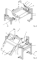
- Fig. 1 shows a part of an embodiment of a transport apparatus 1 according to the invention.
- the transport apparatus 1 comprises a frame 2 and a conveyor 3.
- the conveyor 3 is drivable with respect to the frame 2 in a direction of conveyance X.
- the conveyor 3 comprises a plurality of discrete carriers 4 which are coupled to each other and follow a closed loop under operating conditions.
- the carriers 4 are intended to support and transport respective discrete products such that each carrier 4 supports and transports one product.
- the conveyor 3 is of a type which is called a 'Bomb-bay' or ⁇ split tray' sorter.
- Each of the carriers 4 is provided with tiltable trays which can be opened to drop a product which is destined for a predetermined receiving container (not shown) below the conveyor 3.
- the transport apparatus 1 is further provided with a loading unit 5 for receiving a product.
- the loading unit 5 is located at a certain position along the conveyor 3 and comprises a platform 6 including a flat upper surface for bearing a product.
- the platform 6 is located above the conveyor 3 and forms a bridge across the conveyor 3.
- the platform 6 is slidably mounted to a support 7 and movable with respect to the support 7 by means of a first pneumatic cylinder 8.
- the support 7 is tiltable with respect to the frame 2 about an axis of rotation AR by means of a second pneumatic cylinder 9.
- the second pneumatic cylinder 9 is pivotally coupled to an arm 10 which is fixed to a shaft that in turn is fixed to the support 7.
- the axis of rotation AR extends horizontally and perpendicularly to the direction of conveyance X.
- the platform 6 is movable with respect to the support 7 in a direction perpendicular to the axis of rotation AR.
- the first and second pneumatic cylinders 8, 9 form part of a product transfer device for transferring a product from the loading unit 5 to the conveyor 3.
- the platform 6 is movable between a lying product receiving position in which the upper surface of the platform 6 extends substantially horizontally, which condition is shown in Fig. 2 , and a downwardly directed product releasing position, which condition is shown in Figs. 1 and 3 .
- a lying product receiving position in which the upper surface of the platform 6 extends substantially horizontally
- a downwardly directed product releasing position which condition is shown in Figs. 1 and 3 .
- the first and second pneumatic cylinders 8, 9 are retracted and in the product releasing position the first and second pneumatic cylinders 8, 9 are extended.
- the platform 6 is tilted about the axis of rotation AR as well as translated with respect to the support 7 in downward direction.
- the first cylinder 8 moves from the retracted to the extended position the platform 6 is moved with respect to the support 7 in a direction which has a component in the direction of conveyance X.
- the transport apparatus 1 is provided with a first product detector (not shown) for detecting an empty carrier 4 upstream of the loading unit 5 onto which empty carrier 4 a product from the platform 6 can be transferred.
- the loading unit 5 is provided with a second product detector 11 for detecting a product on the platform 6.
- the second product detector 11 is formed by three sensors for identifying a product on the platform 6, but this may be different in an alternative embodiment. It is even possible that the platform 6 is transparent and the second product detector is located below the platform 6.
- a transparent platform 6 provides the opportunity to locate a product identifier below the platform 6 in order to identify a product that is placed on the platform 6, for example by reading a barcode.
- the transport apparatus 1 is also provided with a controller (not shown) for automatically transferring a product from the loading unit 5 to an empty carrier 4.
- the controller has an input for receiving signals from the first and second product detectors 11 and an output for sending control signals to the first and second pneumatic cylinders 8, 9.
- the controller is configured such that when the first product detector detects an empty carrier 4 upstream of the loading unit 5 and the second product detector 11 identifies a product on the platform 6 the controller will activate the first and second pneumatic cylinders 8, 9 such that the product will be transferred to the empty carrier 4 when it passes the loading unit 5.
- the product may be placed onto the platform 6 manually by an operator or automatically by a robot or the like.
- the sensors of the second product detector 11 may be positioned in such a way that the controller can identify the location of a product on the platform 6 so as to adapt the timing of activating the first and/or second pneumatic cylinders 8, 9 and/or their speed in dependency of the location of the product.
- the controller may be configured such that when the second product detector 11 identifies more than one product at the loading unit 5 the first and second pneumatic cylinders 8, 9 are not activated. In that case an alarm may be generated in order to enable an operator to remove one or more products from the platform 6. It is also possible that a robot automatically removes one or more products from the platform 6.
- the required distance between the conveyor 3 and the platform 6 in the product receiving position depends on the maximum height of products that are transported by the conveyor 3. It may be 50 cm, for example.
- the product releasing position of the platform 6 its upper surface may be inclined by 45° with respect to a horizontal plane, but this may be different. In the latter position a free end of the platform 6 may be close to the conveyor 3, for example a few centimetres above the conveyor 3.
- the conveyor may have a continuous upper face instead of discrete carriers whereas the first product detector detects an empty portion of the upper face rather than an empty carrier.
- the loading unit has an additional device for removing a product from the platform in its product releasing position, for example a pushing device.
Landscapes
- Engineering & Computer Science (AREA)
- Mechanical Engineering (AREA)
- Intermediate Stations On Conveyors (AREA)
- Specific Conveyance Elements (AREA)
- Feeding Of Articles To Conveyors (AREA)
- Control Of Conveyors (AREA)
- Discharge Of Articles From Conveyors (AREA)
Description
- The present invention relates to a transport apparatus, which comprises a frame, a conveyor for conveying discrete products to be sorted which conveyor is drivable with respect to the frame in a direction of conveyance.
- Such a transport apparatus is well-known in the prior art. The conveyor of the known transport apparatus is suitable for conveying discrete products to be sorted. Under operating conditions it will transport discrete products which are located at different locations along the conveyor. In practice there may be several locations at the conveyor which are not occupied and thus suitable for receiving a product to be sorted.
-
JP H08 301438 A - The document
EP 4 163 235 A1 , which is prior art in the sense of Article 54(3) EPC, discloses a transport apparatus , comprising a frame, a conveyor for conveying discrete products to be sorted which conveyor is drivable with respect to the frame in a direction of conveyance , a loading unit for receiving a product which loading unit is located at a position along the conveyor, a product transfer device for transferring a product from the loading unit to the conveyor, a product detector for detecting a free location at the conveyor for receiving a product, and a controller having an input for receiving signals from the product detector and an output for sending a control signal to the product transfer device, wherein the controller is configured such that when the first product detector detects a free location at the conveyor, the product transfer device transfers the product from the loading unit to the free location when the free location passes the loading unit, wherein the loading unit comprises a platform for bearing a product, which platform is mounted to the frame above the conveyor and movable with respect to the frame between a product receiving position and a product releasing position, wherein the product transfer device comprises a driving system for moving the platform from the product receiving position to the product releasing position, hence allowing a product to move downwardly with respect to the platform to the conveyor. - An object of the invention is to provide a transport apparatus with high capacity.
- This object is accomplished with the transport apparatus according to the invention, which comprises a loading unit for receiving a product which loading unit is located at a position along the conveyor, a product transfer device for transferring a product from the loading unit to the conveyor, a first product detector for detecting a free location at the conveyor for receiving a product, a second product detector for detecting a product at the loading unit and a controller having an input for receiving signals from the first and second product detectors, respectively, and an output for sending a control signal to the product transfer device, wherein the controller is configured such that when the first product detector detects a free location at the conveyor and the second product detector detects a product at the loading unit the product transfer device transfers the product from the loading unit to the free location when the free location passes the loading unit, wherein the loading unit comprises a platform for bearing a product, which platform is mounted to the frame above the conveyor and tiltable with respect to the frame about an axis of rotation between a lying product receiving position and a downwardly directed product releasing position, which axis of rotation is angled with respect to the direction of conveyance, wherein the product transfer device comprises a driving system for tilting the platform from the product receiving position to the product releasing position, hence allowing a product to move downwardly with respect to the platform to the conveyor in a direction which has a component in the direction of conveyance.
- An advantage of the transport apparatus according to the invention is that free locations at the conveyor can be provided with respective products such that the capacity of the transport apparatus can be optimized. Since the second product detector detects whether a product is present at the loading unit it is only necessary to supply a product to be sorted to the loading unit. This can be performed manually by an operator, but it is also possible to apply a robot or the like. The second product detector may be configured to detect a unique code of the product that is supplied to the loading unit in order to follow the product during its travelling through the transport apparatus. It is also possible to locate more than one loading unit along the conveyor.
- In the lying product receiving position the platform may have such an orientation that a product on the platform will not automatically move from the platform by gravity. In the product releasing position the platform may have such an orientation that a product will automatically move from the platform by gravity. The inclination of the platform in the product releasing position with respect to a horizontal plane is larger than in the product receiving position. For example the inclination in the product releasing position may be 45°, but different angles are possible.
- Since the platform tilts from the product receiving position to the product releasing position such that a product on the platform can move downwardly in a direction which has a component in the direction of conveyance the product has already a velocity in the same direction as the direction of conveyance of the conveyor upon arriving at the free location of the conveyor. This provides the opportunity to operate the conveyor at a relatively high speed. In fact, the normal to an upper face or bearing surface of the platform in the product releasing position has a component in the direction of conveyance.
- It is noted, that the axis of rotation has a horizontally oriented orientation in order to create the downwardly directed product releasing position.
- The conveyor may comprise a plurality of discrete carriers located behind each other in the direction of conveyance, wherein the first product detector is adapted to detect an empty carrier being a free location at the conveyor. Numerous types of carriers are conceivable. For example, each of the carriers may be provided with a tray that is tiltable in order to drop a product at a predetermined location along the conveyor, such as in case of a so-called 'Bomb-bay' or `split tray' sorter or a tilt tray or cross tray sorter, but it is also conceivable that a pusher moves the product from the tray, i.e. a push tray sorter.
- It is not necessary that the conveyor itself forms a sorter. The conveyor may also supply products to a sorter.
- The platform may be transparent in order to provide a product identifier below the platform so as to identify a product that is placed on the platform, for example by reading a barcode.
- In the product receiving position of the platform an upper face or bearing surface of the platform may extend substantially horizontally.
- The platform may form a bridge above the conveyor. It may be located 50 cm above the conveyor, for example, such that other passing products at the conveyor are not obstructed by the platform when it is in the product receiving position.
- In a preferred embodiment the platform is mounted to the frame via a support which is mounted to the frame and tiltable with respect to the frame about the axis of rotation by the driving system, whereas the platform is movable with respect to the support by the driving system in a direction which has a component in the direction of conveyance, since in that case a product on the platform can be accelerated in the product releasing position by gravity as well as by means of the motion of the platform with respect to the support.
- The platform may be movable with respect to the support in a direction perpendicular to the axis of rotation.
- The controller may be configured such that the driving system tilts the support and moves the platform with respect to the support synchronously.
- The controller may be configured such that when the second product detector identifies more than one product at the loading unit the product transfer device is not activated. The controller may additionally raise an alert such that an operator can remove one or more products from the loading unit. It is also possible that the loading unit comprises a mechanism to remove one or more products from the loading unit to a different location than to the conveyor.
- The platform may have a flat upper surface so as to allow a product to slide or roll downwardly on the upper surface by gravity when the platform is tilted from the product receiving position to the product releasing position. The upper surface may be smooth to facilitate a sliding movement.
- The second product detector may be configured to identify the location of a product on the platform in the direction of conveyance. On the basis of this location information, the timing of activating the driving system and/or the speed of the driving system can be adapted such that the product can be transferred to the free location in an accurate way. For example, the timing of tilting the platform can be advanced or retarded. If the product is placed at the upstream end of the platform instead of in its centre, the start of tilting the platform can be advanced. It is also conceivable to adapt the timing dependent on friction between the platform and the product.
- The apparatus may be provided with a third product detector for identifying a location where a released product from the platform arrives at the conveyor. A signal from the third product detector may be a feedback signal to the controller in order to adjust timing of activating the driving system or to adjust the speed of the driving system.
- The platform may be provided with one or more guides to guide a product during its movement with respect to the platform during tilting the platform from the product receiving position to the product releasing position. This may force a product to follow a predetermined path to the free location at the conveyor. The guide or guides may be located along lateral edges of the platform. It is also possible that the guide or guides form a converging path in the direction of conveyance, for example a funnel shape.
- The distance between the platform and the conveyor may be larger than 50% of the length of the platform as measured in the conveying direction when the platform is in its product receiving position.
- The second product detector may be configured to identify a product on the platform, for example by scanning a code on the product, dimensioning the product or weighing the product. Since the product has a temporarily static position on the platform before being transferred to the intended free location at the conveyor there is a time period to perform the mentioned actions. In practice the time period may be relatively long since the frequency that real free locations pass the loading unit, i.e. the free locations to which respective products will be transferred from the platform, will be lower than the frequency that possible free locations pass the loading unit, since a part of the possible free locations will be occupied by a product. For example, in the event that the conveyor comprises a plurality of discrete carriers, in practice only a part of the carriers that pass the loading unit are empty; hence, the frequency that empty carriers pass the loading unit will be lower than the frequency that all carriers, i.e. empty and loaded carriers, pass the loading unit.
- For the same reason the apparatus may be provided with means for labelling a product on the platform, for example by printing a code on the product.
- The invention will hereafter be elucidated with reference to very schematic drawings showing an embodiment of the invention by way of example.
-
Fig. 1 is a perspective view of a part of an embodiment of a transport apparatus according to the invention. -
Fig. 2 is a similar view asFig. 1 , showing an enlarged part thereof in a first condition. -
Fig. 3 is a similar view asFig. 2 , showing the part in a second condition. -
Fig. 1 shows a part of an embodiment of a transport apparatus 1 according to the invention. The transport apparatus 1 comprises aframe 2 and aconveyor 3. Theconveyor 3 is drivable with respect to theframe 2 in a direction of conveyance X. Theconveyor 3 comprises a plurality of discrete carriers 4 which are coupled to each other and follow a closed loop under operating conditions. The carriers 4 are intended to support and transport respective discrete products such that each carrier 4 supports and transports one product. Theconveyor 3 is of a type which is called a 'Bomb-bay' or `split tray' sorter. Each of the carriers 4 is provided with tiltable trays which can be opened to drop a product which is destined for a predetermined receiving container (not shown) below theconveyor 3. - The transport apparatus 1 is further provided with a
loading unit 5 for receiving a product. Theloading unit 5 is located at a certain position along theconveyor 3 and comprises aplatform 6 including a flat upper surface for bearing a product. Theplatform 6 is located above theconveyor 3 and forms a bridge across theconveyor 3. Theplatform 6 is slidably mounted to asupport 7 and movable with respect to thesupport 7 by means of a first pneumatic cylinder 8. Thesupport 7 is tiltable with respect to theframe 2 about an axis of rotation AR by means of a secondpneumatic cylinder 9. The secondpneumatic cylinder 9 is pivotally coupled to anarm 10 which is fixed to a shaft that in turn is fixed to thesupport 7. The axis of rotation AR extends horizontally and perpendicularly to the direction of conveyance X. Theplatform 6 is movable with respect to thesupport 7 in a direction perpendicular to the axis of rotation AR. The first and secondpneumatic cylinders 8, 9 form part of a product transfer device for transferring a product from theloading unit 5 to theconveyor 3. - The
platform 6 is movable between a lying product receiving position in which the upper surface of theplatform 6 extends substantially horizontally, which condition is shown inFig. 2 , and a downwardly directed product releasing position, which condition is shown inFigs. 1 and3 . In the product receiving position the first and secondpneumatic cylinders 8, 9 are retracted and in the product releasing position the first and secondpneumatic cylinders 8, 9 are extended. Hence, in the latter condition theplatform 6 is tilted about the axis of rotation AR as well as translated with respect to thesupport 7 in downward direction. When the first cylinder 8 moves from the retracted to the extended position theplatform 6 is moved with respect to thesupport 7 in a direction which has a component in the direction of conveyance X. This means that a product on theplatform 6 will be accelerated in the direction of conveyance X by the translative motion, in addition to the acceleration caused by gravity when theplatform 6 is inclined with respect to a horizontal plane. This leads to a fast product release, which allows a high velocity of conveyance of theconveyor 3. - Under normal operating conditions a part of the carriers 4 upstream of the
loading unit 5 are already provided with a product. These loaded carriers 4 pass theloading unit 5 without tilting theplatform 6. Some of the carriers 4 are empty and may be loaded by a product from theplatform 6 when passing theloading unit 5. When theplatform 6 is moved from the product receiving position to the product releasing position a product that is placed on theplatform 6 will slide or roll downwardly with respect to theplatform 6 and arrive on an empty carrier 4 which is passing theloading unit 5. - The transport apparatus 1 is provided with a first product detector (not shown) for detecting an empty carrier 4 upstream of the
loading unit 5 onto which empty carrier 4 a product from theplatform 6 can be transferred. Theloading unit 5 is provided with asecond product detector 11 for detecting a product on theplatform 6. In the embodiment as shown inFigs. 1-3 thesecond product detector 11 is formed by three sensors for identifying a product on theplatform 6, but this may be different in an alternative embodiment. It is even possible that theplatform 6 is transparent and the second product detector is located below theplatform 6. - A
transparent platform 6 provides the opportunity to locate a product identifier below theplatform 6 in order to identify a product that is placed on theplatform 6, for example by reading a barcode. - The transport apparatus 1 is also provided with a controller (not shown) for automatically transferring a product from the
loading unit 5 to an empty carrier 4. The controller has an input for receiving signals from the first andsecond product detectors 11 and an output for sending control signals to the first and secondpneumatic cylinders 8, 9. The controller is configured such that when the first product detector detects an empty carrier 4 upstream of theloading unit 5 and thesecond product detector 11 identifies a product on theplatform 6 the controller will activate the first and secondpneumatic cylinders 8, 9 such that the product will be transferred to the empty carrier 4 when it passes theloading unit 5. The product may be placed onto theplatform 6 manually by an operator or automatically by a robot or the like. - The sensors of the
second product detector 11 may be positioned in such a way that the controller can identify the location of a product on theplatform 6 so as to adapt the timing of activating the first and/or secondpneumatic cylinders 8, 9 and/or their speed in dependency of the location of the product. - The controller may be configured such that when the
second product detector 11 identifies more than one product at theloading unit 5 the first and secondpneumatic cylinders 8, 9 are not activated. In that case an alarm may be generated in order to enable an operator to remove one or more products from theplatform 6. It is also possible that a robot automatically removes one or more products from theplatform 6. - Since the
platform 6 forms a bridge across theconveyor 3 the required distance between theconveyor 3 and theplatform 6 in the product receiving position depends on the maximum height of products that are transported by theconveyor 3. It may be 50 cm, for example. In the product releasing position of theplatform 6 its upper surface may be inclined by 45° with respect to a horizontal plane, but this may be different. In the latter position a free end of theplatform 6 may be close to theconveyor 3, for example a few centimetres above theconveyor 3. - It is noted that when the
platform 6 is in the product receiving position and a product is placed on theplatform 6 it is easy to apply a label onto the product, since the product has a temporarily static position before being transferred to the intended free location at theconveyor 3. - The invention is not limited to the embodiment shown in the drawings and described hereinbefore, which may be varied in different manners, the scope of protection of the invention being defined by the appended claims. For example, the conveyor may have a continuous upper face instead of discrete carriers whereas the first product detector detects an empty portion of the upper face rather than an empty carrier. It is also possible that the loading unit has an additional device for removing a product from the platform in its product releasing position, for example a pushing device.
Claims (14)
- A transport apparatus (1), comprising a frame (2), a conveyor (3) for conveying discrete products to be sorted which conveyor (3) is drivable with respect to the frame (2) in a direction of conveyance (X), a loading unit (5) for receiving a product which loading unit (5) is located at a position along the conveyor (3), a product transfer device (8-10) for transferring a product from the loading unit (5) to the conveyor (3), a first product detector for detecting a free location at the conveyor (3) for receiving a product, a second product detector (11) for detecting a product at the loading unit (5) and a controller having an input for receiving signals from the first and second product detectors (11), respectively, and an output for sending a control signal to the product transfer device (8-10), wherein the controller is configured such that when the first product detector detects a free location at the conveyor (3) and the second product detector (11) detects a product at the loading unit (5) the product transfer device (8-10) transfers the product from the loading unit (5) to the free location when the free location passes the loading unit (5), wherein the loading unit (5) comprises a platform (6) for bearing a product, which platform (6) is mounted to the frame (2) above the conveyor (3) and tiltable with respect to the frame (2) about an axis of rotation (AR) between a lying product receiving position and a downwardly directed product releasing position, which axis of rotation (AR) is angled with respect to the direction of conveyance (X), wherein the product transfer device comprises a driving system (9, 10) for tilting the platform (6) from the product receiving position to the product releasing position, hence allowing a product to move downwardly with respect to the platform (6) to the conveyor (3) in a direction which has a component in the direction of conveyance (X) .
- A transport apparatus (1) according to claim 1, wherein the conveyor (3) comprises a plurality of discrete carriers (4) located behind each other in the direction of conveyance (X), wherein the first product detector is adapted to detect an empty carrier (4) being a free location at the conveyor (3).
- A transport apparatus (1) according to claim 1 or 2, wherein in the product receiving position an upper face of the platform (6) extends substantially horizontally.
- A transport apparatus (1) according to any one of the preceding claims, wherein the axis of rotation (AR) is substantially perpendicular to the direction of conveyance (X).
- A transport apparatus (1) according to any one of the preceding claims, wherein the platform (6) is mounted to the frame (2) via a support (7) which is mounted to the frame (2) and tiltable with respect to the frame (2) about the axis of rotation (AR) by the driving system (8-10), whereas the platform (6) is movable with respect to the support (7) by the driving system (8-10) in a direction which has a component in the direction of conveyance (X).
- A transport apparatus (1) according to claim 5, wherein the platform (6) is movable with respect to the support (7) in a direction perpendicular to the axis of rotation (AR).
- A transport apparatus (1) according to claim 5 or 6, wherein the controller is configured such that the driving system (8-10) tilts the support (7) and moves the platform (6) with respect to the support (7) synchronously.
- A transport apparatus (1) according to any one of the preceding claims, wherein the controller is configured such that when the second product detector (11) identifies more than one product at the loading unit (5) the product transfer device (8-10) is not activated.
- A transport apparatus (1) according to any one of the preceding claims, wherein the platform (6) has a flat upper surface so as to allow a product to slide or roll downwardly on the upper surface by gravity when the platform (6) is tilted from the product receiving position to the product releasing position.
- A transport apparatus (1) according to any one of the preceding claims, wherein the second product detector (11) is configured to identify the location of a product on the platform (6) in the direction of conveyance (X).
- A transport apparatus (1) according to any one of the preceding claims, wherein the apparatus (1) is provided with a third product detector for identifying a location where a released product from the platform (11) arrives at the conveyor (3) .
- A transport apparatus (1) according to any one of the preceding claims, wherein the distance between the platform (11) and the conveyor (3) is larger than 50% of the length of the platform (6) as measured in the conveying direction when the platform (6) is in its product receiving position.
- A transport apparatus (1) according to any one of the preceding claims, wherein the second product detector (11) is configured to identify a product on the platform (11), for example by scanning a code on the product, dimensioning the product or weighing the product.
- A transport apparatus (1) according to any one of the claims 1-12, wherein the apparatus (1) is provided with means for labelling a product on the platform (11), for example by printing a code on the product.
Priority Applications (11)
| Application Number | Priority Date | Filing Date | Title |
|---|---|---|---|
| PL22153305.2T PL4215464T3 (en) | 2022-01-25 | 2022-01-25 | A transport apparatus |
| DK22153305.2T DK4215464T3 (en) | 2022-01-25 | 2022-01-25 | A TRANSPORT DEVICE |
| EP22153305.2A EP4215464B1 (en) | 2022-01-25 | 2022-01-25 | A transport apparatus |
| HUE22153305A HUE069660T2 (en) | 2022-01-25 | 2022-01-25 | A transport apparatus |
| ES22153305T ES3000909T3 (en) | 2022-01-25 | 2022-01-25 | A transport device |
| RS20241355A RS66275B1 (en) | 2022-01-25 | 2022-01-25 | A transport apparatus |
| PT221533052T PT4215464T (en) | 2022-01-25 | 2022-01-25 | A transport apparatus |
| PCT/EP2023/051691 WO2023144145A1 (en) | 2022-01-25 | 2023-01-24 | A transport apparatus |
| US18/832,047 US20250115439A1 (en) | 2022-01-25 | 2023-01-24 | Transport apparatus |
| JP2024543335A JP2025503088A (en) | 2022-01-25 | 2023-01-24 | Conveyor |
| CA3249592A CA3249592A1 (en) | 2022-01-25 | 2023-01-24 | A transport apparatus |
Applications Claiming Priority (1)
| Application Number | Priority Date | Filing Date | Title |
|---|---|---|---|
| EP22153305.2A EP4215464B1 (en) | 2022-01-25 | 2022-01-25 | A transport apparatus |
Publications (2)
| Publication Number | Publication Date |
|---|---|
| EP4215464A1 EP4215464A1 (en) | 2023-07-26 |
| EP4215464B1 true EP4215464B1 (en) | 2024-10-09 |
Family
ID=80035075
Family Applications (1)
| Application Number | Title | Priority Date | Filing Date |
|---|---|---|---|
| EP22153305.2A Active EP4215464B1 (en) | 2022-01-25 | 2022-01-25 | A transport apparatus |
Country Status (11)
| Country | Link |
|---|---|
| US (1) | US20250115439A1 (en) |
| EP (1) | EP4215464B1 (en) |
| JP (1) | JP2025503088A (en) |
| CA (1) | CA3249592A1 (en) |
| DK (1) | DK4215464T3 (en) |
| ES (1) | ES3000909T3 (en) |
| HU (1) | HUE069660T2 (en) |
| PL (1) | PL4215464T3 (en) |
| PT (1) | PT4215464T (en) |
| RS (1) | RS66275B1 (en) |
| WO (1) | WO2023144145A1 (en) |
Citations (1)
| Publication number | Priority date | Publication date | Assignee | Title |
|---|---|---|---|---|
| EP4163235A1 (en) * | 2021-10-07 | 2023-04-12 | Ferag Ag | Device for transferring transported goods between two conveyor devices, a conveyor system and a transfer method |
Family Cites Families (8)
| Publication number | Priority date | Publication date | Assignee | Title |
|---|---|---|---|---|
| JP3094840B2 (en) * | 1995-04-28 | 2000-10-03 | 株式会社ダイフク | Sorting equipment |
| US6220330B1 (en) * | 1998-10-01 | 2001-04-24 | Dorner Mfg. Corp. | Conveyor system incorporating article guide and positioning arrangement for a labeling station |
| US7137234B2 (en) * | 2002-11-19 | 2006-11-21 | Lockheed Martin Corporation | Vertical flat stacking apparatus and method of use |
| US11104527B1 (en) * | 2019-02-04 | 2021-08-31 | Amazon Technologies, Inc. | Tote flipper |
| CN113382940B (en) * | 2019-02-27 | 2023-11-07 | 伯克希尔格雷营业股份有限公司 | Systems and methods for controlling the discharge of objects in containers by vibration |
| KR102119679B1 (en) * | 2020-02-19 | 2020-06-08 | 씨제이제일제당(주) | System for Taking off a Packaging Film from items |
| US11548742B2 (en) * | 2021-04-29 | 2023-01-10 | Intelligrated Headquarters, Llc | Automated container unloader |
| WO2023205696A1 (en) * | 2022-04-20 | 2023-10-26 | Advanced Farm Technologies, Inc. | Item de-binning systems and methods |
-
2022
- 2022-01-25 PL PL22153305.2T patent/PL4215464T3/en unknown
- 2022-01-25 RS RS20241355A patent/RS66275B1/en unknown
- 2022-01-25 ES ES22153305T patent/ES3000909T3/en active Active
- 2022-01-25 DK DK22153305.2T patent/DK4215464T3/en active
- 2022-01-25 HU HUE22153305A patent/HUE069660T2/en unknown
- 2022-01-25 PT PT221533052T patent/PT4215464T/en unknown
- 2022-01-25 EP EP22153305.2A patent/EP4215464B1/en active Active
-
2023
- 2023-01-24 CA CA3249592A patent/CA3249592A1/en active Pending
- 2023-01-24 WO PCT/EP2023/051691 patent/WO2023144145A1/en not_active Ceased
- 2023-01-24 US US18/832,047 patent/US20250115439A1/en active Pending
- 2023-01-24 JP JP2024543335A patent/JP2025503088A/en active Pending
Patent Citations (1)
| Publication number | Priority date | Publication date | Assignee | Title |
|---|---|---|---|---|
| EP4163235A1 (en) * | 2021-10-07 | 2023-04-12 | Ferag Ag | Device for transferring transported goods between two conveyor devices, a conveyor system and a transfer method |
Also Published As
| Publication number | Publication date |
|---|---|
| HUE069660T2 (en) | 2025-04-28 |
| ES3000909T3 (en) | 2025-03-04 |
| DK4215464T3 (en) | 2024-11-18 |
| EP4215464A1 (en) | 2023-07-26 |
| PT4215464T (en) | 2024-12-16 |
| US20250115439A1 (en) | 2025-04-10 |
| RS66275B1 (en) | 2025-01-31 |
| WO2023144145A1 (en) | 2023-08-03 |
| JP2025503088A (en) | 2025-01-30 |
| CA3249592A1 (en) | 2023-08-03 |
| PL4215464T3 (en) | 2025-03-10 |
Similar Documents
| Publication | Publication Date | Title |
|---|---|---|
| EP0918715B1 (en) | High speed, compound, belted diverter and method of operating same | |
| KR102048330B1 (en) | A device for feeding items to a sorting machine and sorting machine | |
| US6323452B1 (en) | Feeding system and method for placing a plurality of objects on a tray of an automated sorting system | |
| US3799319A (en) | Article aligning apparatus | |
| US4396109A (en) | Device for causing holders transporting objects to release the objects | |
| GB2084531A (en) | Feeding articles to a sorter conveyor | |
| JP2009274878A (en) | Article conveyance/delivery method and article conveyance/delivery apparatus | |
| US20040098948A1 (en) | Vertical flat stacking apparatus and method of use | |
| US5326938A (en) | Weighting/labelling apparatus incorporating improved conveyor and method | |
| EP0208024B1 (en) | Apparatus for sorting and removing undesirable objects from a feed belt conveyor | |
| CN114226261A (en) | Luggage conveying and sorting system and automatic luggage conveying and sorting method | |
| CN115959421A (en) | Transport device | |
| JPH10509094A (en) | Equipment for sorting conveyed articles | |
| EP4215464A1 (en) | A transport apparatus | |
| EP0869909B1 (en) | Conveyor loading apparatus | |
| US20240174449A1 (en) | Conveyor system for conveying goods to be conveyed | |
| JP2000247412A (en) | Article conveyance device for cargo handling facility | |
| JP2001048345A (en) | Product sorting device and product sorting system | |
| US20040074738A1 (en) | Transport system for cargo containers, in particular for baggage containers | |
| JP2529523B2 (en) | Transfer equipment | |
| KR102574268B1 (en) | Package sorting device | |
| KR20230088152A (en) | Freight sorting device using data tracking synchronization | |
| JP3621527B2 (en) | Agricultural sorting conveyor | |
| NL2037286B1 (en) | A conveyor device | |
| NL1000966C1 (en) | Trolley loading machine for bags of objects |
Legal Events
| Date | Code | Title | Description |
|---|---|---|---|
| PUAI | Public reference made under article 153(3) epc to a published international application that has entered the european phase |
Free format text: ORIGINAL CODE: 0009012 |
|
| STAA | Information on the status of an ep patent application or granted ep patent |
Free format text: STATUS: THE APPLICATION HAS BEEN PUBLISHED |
|
| AK | Designated contracting states |
Kind code of ref document: A1 Designated state(s): AL AT BE BG CH CY CZ DE DK EE ES FI FR GB GR HR HU IE IS IT LI LT LU LV MC MK MT NL NO PL PT RO RS SE SI SK SM TR |
|
| STAA | Information on the status of an ep patent application or granted ep patent |
Free format text: STATUS: REQUEST FOR EXAMINATION WAS MADE |
|
| 17P | Request for examination filed |
Effective date: 20231129 |
|
| RBV | Designated contracting states (corrected) |
Designated state(s): AL AT BE BG CH CY CZ DE DK EE ES FI FR GB GR HR HU IE IS IT LI LT LU LV MC MK MT NL NO PL PT RO RS SE SI SK SM TR |
|
| GRAP | Despatch of communication of intention to grant a patent |
Free format text: ORIGINAL CODE: EPIDOSNIGR1 |
|
| STAA | Information on the status of an ep patent application or granted ep patent |
Free format text: STATUS: GRANT OF PATENT IS INTENDED |
|
| INTG | Intention to grant announced |
Effective date: 20240503 |
|
| GRAS | Grant fee paid |
Free format text: ORIGINAL CODE: EPIDOSNIGR3 |
|
| GRAA | (expected) grant |
Free format text: ORIGINAL CODE: 0009210 |
|
| STAA | Information on the status of an ep patent application or granted ep patent |
Free format text: STATUS: THE PATENT HAS BEEN GRANTED |
|
| AK | Designated contracting states |
Kind code of ref document: B1 Designated state(s): AL AT BE BG CH CY CZ DE DK EE ES FI FR GB GR HR HU IE IS IT LI LT LU LV MC MK MT NL NO PL PT RO RS SE SI SK SM TR |
|
| REG | Reference to a national code |
Ref country code: CH Ref legal event code: EP |
|
| REG | Reference to a national code |
Ref country code: DE Ref legal event code: R096 Ref document number: 602022006561 Country of ref document: DE |
|
| REG | Reference to a national code |
Ref country code: IE Ref legal event code: FG4D |
|
| REG | Reference to a national code |
Ref country code: DK Ref legal event code: T3 Effective date: 20241114 |
|
| REG | Reference to a national code |
Ref country code: PT Ref legal event code: SC4A Ref document number: 4215464 Country of ref document: PT Date of ref document: 20241216 Kind code of ref document: T Free format text: AVAILABILITY OF NATIONAL TRANSLATION Effective date: 20241210 |
|
| REG | Reference to a national code |
Ref country code: NL Ref legal event code: FP |
|
| REG | Reference to a national code |
Ref country code: SE Ref legal event code: TRGR |
|
| REG | Reference to a national code |
Ref country code: LT Ref legal event code: MG9D |
|
| REG | Reference to a national code |
Ref country code: GR Ref legal event code: EP Ref document number: 20240402942 Country of ref document: GR Effective date: 20250120 |
|
| REG | Reference to a national code |
Ref country code: ES Ref legal event code: FG2A Ref document number: 3000909 Country of ref document: ES Kind code of ref document: T3 Effective date: 20250304 |
|
| PG25 | Lapsed in a contracting state [announced via postgrant information from national office to epo] |
Ref country code: HR Free format text: LAPSE BECAUSE OF FAILURE TO SUBMIT A TRANSLATION OF THE DESCRIPTION OR TO PAY THE FEE WITHIN THE PRESCRIBED TIME-LIMIT Effective date: 20241009 Ref country code: IS Free format text: LAPSE BECAUSE OF FAILURE TO SUBMIT A TRANSLATION OF THE DESCRIPTION OR TO PAY THE FEE WITHIN THE PRESCRIBED TIME-LIMIT Effective date: 20250209 |
|
| PG25 | Lapsed in a contracting state [announced via postgrant information from national office to epo] |
Ref country code: FI Free format text: LAPSE BECAUSE OF FAILURE TO SUBMIT A TRANSLATION OF THE DESCRIPTION OR TO PAY THE FEE WITHIN THE PRESCRIBED TIME-LIMIT Effective date: 20241009 |
|
| PG25 | Lapsed in a contracting state [announced via postgrant information from national office to epo] |
Ref country code: BG Free format text: LAPSE BECAUSE OF FAILURE TO SUBMIT A TRANSLATION OF THE DESCRIPTION OR TO PAY THE FEE WITHIN THE PRESCRIBED TIME-LIMIT Effective date: 20241009 |
|
| PG25 | Lapsed in a contracting state [announced via postgrant information from national office to epo] |
Ref country code: NO Free format text: LAPSE BECAUSE OF FAILURE TO SUBMIT A TRANSLATION OF THE DESCRIPTION OR TO PAY THE FEE WITHIN THE PRESCRIBED TIME-LIMIT Effective date: 20250109 |
|
| PG25 | Lapsed in a contracting state [announced via postgrant information from national office to epo] |
Ref country code: LV Free format text: LAPSE BECAUSE OF FAILURE TO SUBMIT A TRANSLATION OF THE DESCRIPTION OR TO PAY THE FEE WITHIN THE PRESCRIBED TIME-LIMIT Effective date: 20241009 |
|
| REG | Reference to a national code |
Ref country code: HU Ref legal event code: AG4A Ref document number: E069660 Country of ref document: HU |
|
| PG25 | Lapsed in a contracting state [announced via postgrant information from national office to epo] |
Ref country code: SM Free format text: LAPSE BECAUSE OF FAILURE TO SUBMIT A TRANSLATION OF THE DESCRIPTION OR TO PAY THE FEE WITHIN THE PRESCRIBED TIME-LIMIT Effective date: 20241009 |
|
| REG | Reference to a national code |
Ref country code: DE Ref legal event code: R097 Ref document number: 602022006561 Country of ref document: DE |
|
| PG25 | Lapsed in a contracting state [announced via postgrant information from national office to epo] |
Ref country code: EE Free format text: LAPSE BECAUSE OF FAILURE TO SUBMIT A TRANSLATION OF THE DESCRIPTION OR TO PAY THE FEE WITHIN THE PRESCRIBED TIME-LIMIT Effective date: 20241009 |
|
| PG25 | Lapsed in a contracting state [announced via postgrant information from national office to epo] |
Ref country code: SK Free format text: LAPSE BECAUSE OF FAILURE TO SUBMIT A TRANSLATION OF THE DESCRIPTION OR TO PAY THE FEE WITHIN THE PRESCRIBED TIME-LIMIT Effective date: 20241009 |
|
| PG25 | Lapsed in a contracting state [announced via postgrant information from national office to epo] |
Ref country code: CZ Free format text: LAPSE BECAUSE OF FAILURE TO SUBMIT A TRANSLATION OF THE DESCRIPTION OR TO PAY THE FEE WITHIN THE PRESCRIBED TIME-LIMIT Effective date: 20241009 |
|
| PLBE | No opposition filed within time limit |
Free format text: ORIGINAL CODE: 0009261 |
|
| STAA | Information on the status of an ep patent application or granted ep patent |
Free format text: STATUS: NO OPPOSITION FILED WITHIN TIME LIMIT |
|
| REG | Reference to a national code |
Ref country code: CH Ref legal event code: PL |
|
| PG25 | Lapsed in a contracting state [announced via postgrant information from national office to epo] |
Ref country code: MC Free format text: LAPSE BECAUSE OF FAILURE TO SUBMIT A TRANSLATION OF THE DESCRIPTION OR TO PAY THE FEE WITHIN THE PRESCRIBED TIME-LIMIT Effective date: 20241009 Ref country code: LU Free format text: LAPSE BECAUSE OF NON-PAYMENT OF DUE FEES Effective date: 20250125 |
|
| 26N | No opposition filed |
Effective date: 20250710 |
|
| P01 | Opt-out of the competence of the unified patent court (upc) registered |
Free format text: CASE NUMBER: UPC_APP_3791_4215464/2025 Effective date: 20250820 |
|
| PG25 | Lapsed in a contracting state [announced via postgrant information from national office to epo] |
Ref country code: CH Free format text: LAPSE BECAUSE OF NON-PAYMENT OF DUE FEES Effective date: 20250131 |
|
| REG | Reference to a national code |
Ref country code: AT Ref legal event code: UEP Ref document number: 1730403 Country of ref document: AT Kind code of ref document: T Effective date: 20241009 |
|
| PG25 | Lapsed in a contracting state [announced via postgrant information from national office to epo] |
Ref country code: IE Free format text: LAPSE BECAUSE OF NON-PAYMENT OF DUE FEES Effective date: 20250125 |
|
| PGFP | Annual fee paid to national office [announced via postgrant information from national office to epo] |
Ref country code: NL Payment date: 20260126 Year of fee payment: 5 |
|
| PGFP | Annual fee paid to national office [announced via postgrant information from national office to epo] |
Ref country code: HU Payment date: 20260109 Year of fee payment: 5 |
|
| PGFP | Annual fee paid to national office [announced via postgrant information from national office to epo] |
Ref country code: SE Payment date: 20260127 Year of fee payment: 5 |
|
| PGFP | Annual fee paid to national office [announced via postgrant information from national office to epo] |
Ref country code: GB Payment date: 20260127 Year of fee payment: 5 |
|
| PGFP | Annual fee paid to national office [announced via postgrant information from national office to epo] |
Ref country code: ES Payment date: 20260202 Year of fee payment: 5 |
|
| PGFP | Annual fee paid to national office [announced via postgrant information from national office to epo] |
Ref country code: DK Payment date: 20260126 Year of fee payment: 5 Ref country code: DE Payment date: 20260128 Year of fee payment: 5 |
|
| PGFP | Annual fee paid to national office [announced via postgrant information from national office to epo] |
Ref country code: AT Payment date: 20260301 Year of fee payment: 5 |
|
| PGFP | Annual fee paid to national office [announced via postgrant information from national office to epo] |
Ref country code: RO Payment date: 20260113 Year of fee payment: 5 Ref country code: BE Payment date: 20260127 Year of fee payment: 5 Ref country code: IT Payment date: 20260121 Year of fee payment: 5 |
|
| PGFP | Annual fee paid to national office [announced via postgrant information from national office to epo] |
Ref country code: RS Payment date: 20260105 Year of fee payment: 5 |
|
| PGFP | Annual fee paid to national office [announced via postgrant information from national office to epo] |
Ref country code: FR Payment date: 20260126 Year of fee payment: 5 |
|
| PGFP | Annual fee paid to national office [announced via postgrant information from national office to epo] |
Ref country code: PT Payment date: 20260108 Year of fee payment: 5 |
|
| PGFP | Annual fee paid to national office [announced via postgrant information from national office to epo] |
Ref country code: GR Payment date: 20260127 Year of fee payment: 5 Ref country code: PL Payment date: 20260108 Year of fee payment: 5 |