EP4215450A1 - Cup and method for producing same - Google Patents
Cup and method for producing same Download PDFInfo
- Publication number
- EP4215450A1 EP4215450A1 EP21869128.5A EP21869128A EP4215450A1 EP 4215450 A1 EP4215450 A1 EP 4215450A1 EP 21869128 A EP21869128 A EP 21869128A EP 4215450 A1 EP4215450 A1 EP 4215450A1
- Authority
- EP
- European Patent Office
- Prior art keywords
- cup
- curled
- tip end
- body portion
- curvature
- Prior art date
- Legal status (The legal status is an assumption and is not a legal conclusion. Google has not performed a legal analysis and makes no representation as to the accuracy of the status listed.)
- Withdrawn
Links
Images



Classifications
-
- B—PERFORMING OPERATIONS; TRANSPORTING
- B65—CONVEYING; PACKING; STORING; HANDLING THIN OR FILAMENTARY MATERIAL
- B65D—CONTAINERS FOR STORAGE OR TRANSPORT OF ARTICLES OR MATERIALS, e.g. BAGS, BARRELS, BOTTLES, BOXES, CANS, CARTONS, CRATES, DRUMS, JARS, TANKS, HOPPERS, FORWARDING CONTAINERS; ACCESSORIES, CLOSURES, OR FITTINGS THEREFOR; PACKAGING ELEMENTS; PACKAGES
- B65D1/00—Rigid or semi-rigid containers having bodies formed in one piece, e.g. by casting metallic material, by moulding plastics, by blowing vitreous material, by throwing ceramic material, by moulding pulped fibrous material or by deep-drawing operations performed on sheet material
- B65D1/22—Boxes or like containers with side walls of substantial depth for enclosing contents
- B65D1/26—Thin-walled containers, e.g. formed by deep-drawing operations
- B65D1/265—Drinking cups
-
- B—PERFORMING OPERATIONS; TRANSPORTING
- B65—CONVEYING; PACKING; STORING; HANDLING THIN OR FILAMENTARY MATERIAL
- B65D—CONTAINERS FOR STORAGE OR TRANSPORT OF ARTICLES OR MATERIALS, e.g. BAGS, BARRELS, BOTTLES, BOXES, CANS, CARTONS, CRATES, DRUMS, JARS, TANKS, HOPPERS, FORWARDING CONTAINERS; ACCESSORIES, CLOSURES, OR FITTINGS THEREFOR; PACKAGING ELEMENTS; PACKAGES
- B65D7/00—Containers having bodies formed by interconnecting or uniting two or more rigid, or substantially rigid, components made wholly or mainly of metal
- B65D7/02—Containers having bodies formed by interconnecting or uniting two or more rigid, or substantially rigid, components made wholly or mainly of metal characterised by shape
- B65D7/04—Containers having bodies formed by interconnecting or uniting two or more rigid, or substantially rigid, components made wholly or mainly of metal characterised by shape of curved cross-section, e.g. cans of circular or elliptical cross-section
-
- B—PERFORMING OPERATIONS; TRANSPORTING
- B21—MECHANICAL METAL-WORKING WITHOUT ESSENTIALLY REMOVING MATERIAL; PUNCHING METAL
- B21D—WORKING OR PROCESSING OF SHEET METAL OR METAL TUBES, RODS OR PROFILES WITHOUT ESSENTIALLY REMOVING MATERIAL; PUNCHING METAL
- B21D19/00—Flanging or other edge treatment, e.g. of tubes
- B21D19/12—Edge-curling
-
- B—PERFORMING OPERATIONS; TRANSPORTING
- B21—MECHANICAL METAL-WORKING WITHOUT ESSENTIALLY REMOVING MATERIAL; PUNCHING METAL
- B21D—WORKING OR PROCESSING OF SHEET METAL OR METAL TUBES, RODS OR PROFILES WITHOUT ESSENTIALLY REMOVING MATERIAL; PUNCHING METAL
- B21D51/00—Making hollow objects
- B21D51/16—Making hollow objects characterised by the use of the objects
-
- B—PERFORMING OPERATIONS; TRANSPORTING
- B21—MECHANICAL METAL-WORKING WITHOUT ESSENTIALLY REMOVING MATERIAL; PUNCHING METAL
- B21D—WORKING OR PROCESSING OF SHEET METAL OR METAL TUBES, RODS OR PROFILES WITHOUT ESSENTIALLY REMOVING MATERIAL; PUNCHING METAL
- B21D51/00—Making hollow objects
- B21D51/16—Making hollow objects characterised by the use of the objects
- B21D51/26—Making hollow objects characterised by the use of the objects cans or tins; Closing same in a permanent manner
- B21D51/2615—Edge treatment of cans or tins
-
- B—PERFORMING OPERATIONS; TRANSPORTING
- B21—MECHANICAL METAL-WORKING WITHOUT ESSENTIALLY REMOVING MATERIAL; PUNCHING METAL
- B21D—WORKING OR PROCESSING OF SHEET METAL OR METAL TUBES, RODS OR PROFILES WITHOUT ESSENTIALLY REMOVING MATERIAL; PUNCHING METAL
- B21D51/00—Making hollow objects
- B21D51/16—Making hollow objects characterised by the use of the objects
- B21D51/26—Making hollow objects characterised by the use of the objects cans or tins; Closing same in a permanent manner
- B21D51/2615—Edge treatment of cans or tins
- B21D51/2623—Curling
-
- B—PERFORMING OPERATIONS; TRANSPORTING
- B65—CONVEYING; PACKING; STORING; HANDLING THIN OR FILAMENTARY MATERIAL
- B65D—CONTAINERS FOR STORAGE OR TRANSPORT OF ARTICLES OR MATERIALS, e.g. BAGS, BARRELS, BOTTLES, BOXES, CANS, CARTONS, CRATES, DRUMS, JARS, TANKS, HOPPERS, FORWARDING CONTAINERS; ACCESSORIES, CLOSURES, OR FITTINGS THEREFOR; PACKAGING ELEMENTS; PACKAGES
- B65D1/00—Rigid or semi-rigid containers having bodies formed in one piece, e.g. by casting metallic material, by moulding plastics, by blowing vitreous material, by throwing ceramic material, by moulding pulped fibrous material or by deep-drawing operations performed on sheet material
- B65D1/22—Boxes or like containers with side walls of substantial depth for enclosing contents
- B65D1/26—Thin-walled containers, e.g. formed by deep-drawing operations
-
- B—PERFORMING OPERATIONS; TRANSPORTING
- B65—CONVEYING; PACKING; STORING; HANDLING THIN OR FILAMENTARY MATERIAL
- B65D—CONTAINERS FOR STORAGE OR TRANSPORT OF ARTICLES OR MATERIALS, e.g. BAGS, BARRELS, BOTTLES, BOXES, CANS, CARTONS, CRATES, DRUMS, JARS, TANKS, HOPPERS, FORWARDING CONTAINERS; ACCESSORIES, CLOSURES, OR FITTINGS THEREFOR; PACKAGING ELEMENTS; PACKAGES
- B65D7/00—Containers having bodies formed by interconnecting or uniting two or more rigid, or substantially rigid, components made wholly or mainly of metal
- B65D7/42—Details of metal walls
- B65D7/48—Local reinforcements, e.g. adjacent closures
-
- Y—GENERAL TAGGING OF NEW TECHNOLOGICAL DEVELOPMENTS; GENERAL TAGGING OF CROSS-SECTIONAL TECHNOLOGIES SPANNING OVER SEVERAL SECTIONS OF THE IPC; TECHNICAL SUBJECTS COVERED BY FORMER USPC CROSS-REFERENCE ART COLLECTIONS [XRACs] AND DIGESTS
- Y02—TECHNOLOGIES OR APPLICATIONS FOR MITIGATION OR ADAPTATION AGAINST CLIMATE CHANGE
- Y02W—CLIMATE CHANGE MITIGATION TECHNOLOGIES RELATED TO WASTEWATER TREATMENT OR WASTE MANAGEMENT
- Y02W30/00—Technologies for solid waste management
- Y02W30/50—Reuse, recycling or recovery technologies
- Y02W30/80—Packaging reuse or recycling, e.g. of multilayer packaging
Definitions
- the present invention relates to a cup made of metal open on an upper surface side, and including a bottom portion and a body portion and a method of manufacturing the same.
- a cup made of metal, open on an upper surface side, and used as tableware or as a cup to be filled with beverages, food, or the like is well known (refer to Patent Document 1 or the like), and can conceivably be applied.
- cups open on an upper surface side, cups made of metal that are washed and used many times, such as those used for tableware, are well known.
- a certain plate thickness is necessary to increase strength, resulting in higher material costs and molding costs and a heavier weight, thus making the cup a highly problematic alternative to cups made of paper, plastic, or the like.
- metal cups made of thin materials can be conceivably used as tableware, while reducing material costs and molding costs and achieving a lighter weight.
- the tip end of the upper opening side of the body portion needs to be protected since it is in direct contact with the mouth or hand during use, washing, or the like.
- the cup when using thin materials, the cup is liable to be deformed and needs to be reinforced.
- the present invention has been made to solve the above-described problems, and an object of the present invention is to provide a cup made of metal and a method of manufacturing the same, which can reduce material costs and molding costs, reduce weight, prevent deformation, prevent a user's mouth or hand from touching an edge of a metal material, prevent a scratch from generating when the cup comes into contact with an adjacent cup, and prevent a hygiene problem.
- the cup according to the present invention is a cup made of metal open on an upper surface side, and including a bottom portion and a body portion, in which the body portion includes a curled portion at a tip end on an upper opening side, the curled portion includes a curvature region from the body portion toward the tip end, and a section at least from the body portion to a lowermost portion of the curled portion in the curvature region is configured to have a radius of curvature decreasing stepwise or continuously, thereby solving the above-described problems.
- a method of manufacturing a cup according to the present invention is a method of manufacturing a cup made of metal open on an upper surface side, and including a bottom portion and a body portion, in which a tip end on an upper opening side of a body portion of a cup material is deformed outward, and then the tip end on the upper opening side of the body portion that has been deformed is further processed to form a curled portion, thereby solving the above-described problems.
- the curled portion includes a curvature region from the body portion toward a tip end, and a section at least from the body portion to a lowermost portion of the curled portion in the curvature region is configured to have a radius of curvature that decreases stepwise or continuously, so that the curvature region of the curled portion sufficiently reinforces the shape to prevent deformation, and an edge of a metal material at the tip end of the curled portion can be positioned away from the body portion, thereby easily discharging liquid that has entered the inside of the curled shape.
- edge of the metal material at the tip end of the curled portion can be directed toward the body portion side with a small radius of curvature, so that a user's mouth or hand can be prevented from touching the edge and occurrence of a scratch can be prevented when coming into contact with an adjacent cup.
- the edge of the metal material at the tip end of the curled portion is directed toward the body portion and upward from the horizontal, thus more reliably preventing a user's mouth or hand from touching the edge.
- a tip end on an upper opening side of a body portion of a cup material is deformed outward, and then the tip end on the upper opening side of the body portion that has been deformed is further processed to form a curled portion, so that a cup can be manufactured in which the curled portion includes a curvature region from the body portion toward a tip end, and a section at least from the body portion to a lowermost portion of the curled portion in the curvature region is configured to have a radius of curvature that decreases stepwise or continuously.
- a cup 100 which is an embodiment of the present invention, has an alternative form to well-known paper cups and plastic cups, and includes a bottom portion 101 and a body portion 102, is made of metal, and includes an upper opening 103 open on an upper surface side.
- a curled portion 110 is provided at the tip end on the upper opening 103 side of the body portion 102.
- the body portion 102 is formed in a shape in which an upper portion thereof expands outward except for the vicinity of the bottom portion 101 and the vicinity of the upper opening 103.
- the curled portion 110 is provided at the upper tip end portion of the body portion 102, and includes a curvature region 111 extending from the body portion 102 toward a tip end 110s.
- a section from the body portion 102 to a lowermost portion 110u of the curled portion 110 in the curvature region 111 is configured so that the radius of curvature decreases stepwise or continuously.
- the tip end 110s of the curled portion 110 is positioned above the lowermost portion 110u of the curled portion 110, and the curled portion 110 includes a portion closer to a side wall of the body portion 102 than the lowermost portion 110u on the tip end 110s side compared with the lowermost portion 110u.
- a maximum radius of curvature R1 is from 1.2 to 2.0 mm, preferably from 1.2 to 1.25 mm, and a minimum radius of curvature R2 is from 0.5 to 1.0 mm in the section from the body portion 102 to the lowermost portion 110u of the curled portion 110.
- a horizontal width W between an inner periphery of the side wall of the body portion 102 and an outermost peripheral portion 110g of the curled portion 110 is from 2.0 to 5.0 mm, preferably 2.5 mm.
- a height H1 from the lowermost portion 110u to an uppermost portion 110t of the curled portion 110 is from 1.0 to 5.0 mm, preferably 2.7 mm or less.
- a distance H2 in the height direction between the tip end 110s of the curled portion 110 and the lowermost portion 110u of the curled portion 110 is 0.3 mm or greater, preferably 0.5 mm or greater in order to prevent a mouth or hand from directly touching the tip end 110s.
- a distance C in the horizontal direction between a portion of the curled portion closest to the side wall of the body portion and an outer periphery of the side wall of the body portion is preferably 1.0 mm or less in order to prevent a mouth or hand from directly touching the tip end 110s, and is preferably 0.5 mm or greater in order to discharge liquid that has entered the inside of the curled shape.
- a rising angle ⁇ of a line connecting the lowermost portion 110u of the curled portion 110 and the tip end 110s of the curled portion 110 with respect to the horizontal direction is preferably in the range from 1° to 70°, particularly from 5° to 70°, and more preferably from 20° to 70°.
- the tip end 110s and the outer periphery of the side wall of the body portion are close to each other, but when there is a certain distance for the convenience of equipment or dischargeability of the liquid entering the inside of the curled shape, it is desirable that the angle be 40° or greater, and it is desirable that the angle be 50° or less for the discharge of the liquid entering the inside of the curled shape.
- a curl forming tool 210 is rotatable about a tool rotation axis 212, includes a pressing curved surface 211 having a radius of curvature Rt in a cross-sectional view including the tool rotation axis 212, and a plurality of curl forming tools 210 are disposed on a circumference formed by an upper opening 203 of a body portion 202 of a cup material 200.
- the tip end on an upper opening 203 side of the body portion 202 is pressed against the pressing curved surface 211 of the curl forming tool 210, so that the tip end on the upper opening 203 side of the body portion 202 is deformed outward along the radius of curvature Rt of the pressing curved surface 211 to form the curled portion 110 of the cup 100.
- the body portion 202 is reduced in diameter to form a tapered portion, whereby the cup 100 made of metal as illustrated in FIG. 1 is obtained.
- the method of forming the curled portion 110 is not limited to the following.
- the curled portion 110 is processed a plurality of times with a plurality of curl forming tools 210 having the pressing curved surfaces 211 with different radii of curvature to be formed into a final shape.
- the curled portion 110 whose radius of curvature decreases stepwise from the body portion 102 of the curvature region as illustrated in FIG. 5 can be formed. This prevents direct contact of the tip end of the curled portion 110 with the mouth or hand, and facilitates the discharge of liquid that has entered the inside of the curled shape.
- the curl forming tool and the cup are relatively moved while rotating them with the center of the curl forming tool or the center of the cup material as an axis to deform the entire circumference of the tip end on the upper opening side of the body portion of the cup material outward, and then the entire circumference of the tip end on the upper opening side of the deformed body portion is further processed to form the curled portion.
- a portion indicated by a dotted line in FIG. 5 illustrates a case of being processed with the pressing curved surface 211 having the same radius of curvature Rt1, and in this case, it is difficult to prevent a mouth or hand from being directly touched by the tip end of the curled portion 110 and to discharge the liquid that has entered the inside of the curled shape.
- the radius of curvature of the previously processed portion of the curled portion 110 may slightly increase at the time of the next processing. Therefore, a straight portion close to a straight line (having a large radius of curvature) in a cross-sectional view may be formed in the vicinity of the tip end 110s.
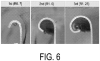
- FIG. 6 illustrates an example of first processing with an initial curl forming tool having the pressing curved surface 211 with a radius of curvature of 0.7 mm, then processing with an intermediate curl forming tool having the pressing curved surface 211 with a radius of curvature of 1.0 mm, and finally processing with a final curl forming tool having the pressing curved surface 211 with a radius of curvature of 1.25 mm, where a straight portion having a large radius of curvature is formed on the tip end side.
- FIG. 7 illustrates an example of first processing with an initial curl forming tool having the pressing curved surface 211 with a radius of curvature of 0.7 mm, then processing with a final curl forming tool having the pressing curved surface 211 with a radius of curvature of 1.25 mm, where a straight portion having a large radius of curvature is formed on the tip end side.
- the curled shape is formed so that the radius of curvature decreases stepwise or continuously in at least the section from the body portion 102 to the lowermost portion 110u of the curled portion 110 in the curvature region 111 by processing a plurality of times with the plurality of curl forming tools 210 having the pressing curved surfaces 211 with different radii of curvature, thereby preventing the tip end of the curled portion 110 from directly touching a mouth or hand, and facilitating the discharge of liquid that has entered the inside of the curled shape.
- the curl forming tool may be of any type as long as the radius of curvature of the curled portion during processing can be changed, the number of times processing is performed may be any number of times, and one continuous processing may be performed depending on the type of processing tool.
- the tapered portion of the body portion 102 of the cup 100 after forming the curled portion 110, the rigidity of the curled portion 110 is increased, and the deformation of the can is suppressed, thereby facilitating processing.
- the tapered portion may be formed before processing the curled portion 110, and the cup 100 may have a shape without the tapered portion.
Landscapes
- Engineering & Computer Science (AREA)
- Mechanical Engineering (AREA)
- Ceramic Engineering (AREA)
- Table Devices Or Equipment (AREA)
- Containers Having Bodies Formed In One Piece (AREA)
- Forging (AREA)
Abstract
Description
- The present invention relates to a cup made of metal open on an upper surface side, and including a bottom portion and a body portion and a method of manufacturing the same.
- In recent years, in order to conserve resources, reduce waste, and the like, there has been a demand for a lightweight, inexpensive, and easily recyclable cup that can be used as an alternative to a cup made of paper, plastic, or the like.
- A cup made of metal, open on an upper surface side, and used as tableware or as a cup to be filled with beverages, food, or the like is well known (refer to Patent Document 1 or the like), and can conceivably be applied.
-
- Patent Document 1:
JP 2020-093847 A - Patent Document 2:
JP 2020-508874 A - As known cups open on an upper surface side, cups made of metal that are washed and used many times, such as those used for tableware, are well known. However, because of the need to increase durability in consideration of long-term use, a certain plate thickness is necessary to increase strength, resulting in higher material costs and molding costs and a heavier weight, thus making the cup a highly problematic alternative to cups made of paper, plastic, or the like.
- In recent years, the recycling capabilities for metal cans have improved, and thus metal cups made of thin materials can be conceivably used as tableware, while reducing material costs and molding costs and achieving a lighter weight.
- In particular, when using thin materials, the tip end of the upper opening side of the body portion needs to be protected since it is in direct contact with the mouth or hand during use, washing, or the like.
- Further, when using thin materials, the cup is liable to be deformed and needs to be reinforced.
- As a cup having such a function, there is known a cup in which a tip end on an upper opening side of a body portion is processed into a curled shape (see Patent Documents 1, 2).
- However, in these known techniques, when a liquid enters the inside of the curled shape, the liquid cannot be easily discharged. Therefore, there is a problem in terms of hygiene in applications where a user cleans and repeatedly uses the cup.
- In addition, depending on the position of the tip end of the curl, there is a possibility that protection from direct contact with the mouth or hand is insufficient or a scratch is generated when the cup comes into contact with an adjacent cup.
- The present invention has been made to solve the above-described problems, and an object of the present invention is to provide a cup made of metal and a method of manufacturing the same, which can reduce material costs and molding costs, reduce weight, prevent deformation, prevent a user's mouth or hand from touching an edge of a metal material, prevent a scratch from generating when the cup comes into contact with an adjacent cup, and prevent a hygiene problem.
- The cup according to the present invention is a cup made of metal open on an upper surface side, and including a bottom portion and a body portion, in which the body portion includes a curled portion at a tip end on an upper opening side, the curled portion includes a curvature region from the body portion toward the tip end, and a section at least from the body portion to a lowermost portion of the curled portion in the curvature region is configured to have a radius of curvature decreasing stepwise or continuously, thereby solving the above-described problems.
- A method of manufacturing a cup according to the present invention is a method of manufacturing a cup made of metal open on an upper surface side, and including a bottom portion and a body portion, in which a tip end on an upper opening side of a body portion of a cup material is deformed outward, and then the tip end on the upper opening side of the body portion that has been deformed is further processed to form a curled portion, thereby solving the above-described problems.
- According to the cup of claim 1 of the present invention, the curled portion includes a curvature region from the body portion toward a tip end, and a section at least from the body portion to a lowermost portion of the curled portion in the curvature region is configured to have a radius of curvature that decreases stepwise or continuously, so that the curvature region of the curled portion sufficiently reinforces the shape to prevent deformation, and an edge of a metal material at the tip end of the curled portion can be positioned away from the body portion, thereby easily discharging liquid that has entered the inside of the curled shape.
- Further, the edge of the metal material at the tip end of the curled portion can be directed toward the body portion side with a small radius of curvature, so that a user's mouth or hand can be prevented from touching the edge and occurrence of a scratch can be prevented when coming into contact with an adjacent cup.
- According to the configuration recited in claim 2, the edge of the metal material at the tip end of the curled portion is directed toward the body portion and upward from the horizontal, thus more reliably preventing a user's mouth or hand from touching the edge.
- According to the method of manufacturing a cup of claim 9 of the present invention, a tip end on an upper opening side of a body portion of a cup material is deformed outward, and then the tip end on the upper opening side of the body portion that has been deformed is further processed to form a curled portion, so that a cup can be manufactured in which the curled portion includes a curvature region from the body portion toward a tip end, and a section at least from the body portion to a lowermost portion of the curled portion in the curvature region is configured to have a radius of curvature that decreases stepwise or continuously.
-
-
FIG. 1 is a perspective view of a cup according to an embodiment of the present invention. -
FIG. 2 is a cross-sectional explanatory view of a curled portion of the cup according to the embodiment of the present invention. -
FIG. 3 is a diagram illustrating a step of forming the curled portion of the cup according to the embodiment of the present invention. -
FIG. 4 is a diagram illustrating a step of forming the curled portion of the cup according to the embodiment of the present invention. -
FIG. 5 is a cross-sectional explanatory view of the curled portion of the cup according to the embodiment of the present invention. -
FIG. 6 is a cross-sectional view of the curled portion of the cup according to the embodiment of the present invention. -
FIG. 7 is a cross-sectional view of a curled portion of a cup according to another embodiment of the present invention. - As illustrated in
FIG. 1 , acup 100, which is an embodiment of the present invention, has an alternative form to well-known paper cups and plastic cups, and includes abottom portion 101 and abody portion 102, is made of metal, and includes anupper opening 103 open on an upper surface side. - A
curled portion 110 is provided at the tip end on theupper opening 103 side of thebody portion 102. - In the present embodiment, the
body portion 102 is formed in a shape in which an upper portion thereof expands outward except for the vicinity of thebottom portion 101 and the vicinity of theupper opening 103. - As illustrated in
FIG. 2 , thecurled portion 110 is provided at the upper tip end portion of thebody portion 102, and includes acurvature region 111 extending from thebody portion 102 toward atip end 110s. - A section from the
body portion 102 to alowermost portion 110u of thecurled portion 110 in thecurvature region 111 is configured so that the radius of curvature decreases stepwise or continuously. - In addition, the
tip end 110s of thecurled portion 110 is positioned above thelowermost portion 110u of thecurled portion 110, and thecurled portion 110 includes a portion closer to a side wall of thebody portion 102 than thelowermost portion 110u on thetip end 110s side compared with thelowermost portion 110u. - In the
curvature region 111, it is desirable that a maximum radius of curvature R1 is from 1.2 to 2.0 mm, preferably from 1.2 to 1.25 mm, and a minimum radius of curvature R2 is from 0.5 to 1.0 mm in the section from thebody portion 102 to thelowermost portion 110u of thecurled portion 110. - Further, it is desirable that a horizontal width W between an inner periphery of the side wall of the
body portion 102 and an outermost peripheral portion 110g of thecurled portion 110 is from 2.0 to 5.0 mm, preferably 2.5 mm. - A height H1 from the
lowermost portion 110u to anuppermost portion 110t of thecurled portion 110 is from 1.0 to 5.0 mm, preferably 2.7 mm or less. - These numerical values are suitable for optimizing the feel of the overall size and shape of the
curled portion 110 and for optimizing storage and handling. - It is desirable that a distance H2 in the height direction between the
tip end 110s of thecurled portion 110 and thelowermost portion 110u of thecurled portion 110 is 0.3 mm or greater, preferably 0.5 mm or greater in order to prevent a mouth or hand from directly touching thetip end 110s. - A distance C in the horizontal direction between a portion of the curled portion closest to the side wall of the body portion and an outer periphery of the side wall of the body portion is preferably 1.0 mm or less in order to prevent a mouth or hand from directly touching the
tip end 110s, and is preferably 0.5 mm or greater in order to discharge liquid that has entered the inside of the curled shape. - A rising angle θ of a line connecting the
lowermost portion 110u of thecurled portion 110 and thetip end 110s of thecurled portion 110 with respect to the horizontal direction is preferably in the range from 1° to 70°, particularly from 5° to 70°, and more preferably from 20° to 70°. In order to prevent a mouth or hand from directly touching thetip end 110s, it is desirable that thetip end 110s and the outer periphery of the side wall of the body portion are close to each other, but when there is a certain distance for the convenience of equipment or dischargeability of the liquid entering the inside of the curled shape, it is desirable that the angle be 40° or greater, and it is desirable that the angle be 50° or less for the discharge of the liquid entering the inside of the curled shape. - An embodiment of a method of manufacturing the
cup 100 including the above-describedcurled portion 110 will be described below. - As illustrated in
FIGS. 3 and4 , acurl forming tool 210 is rotatable about atool rotation axis 212, includes a pressingcurved surface 211 having a radius of curvature Rt in a cross-sectional view including thetool rotation axis 212, and a plurality ofcurl forming tools 210 are disposed on a circumference formed by anupper opening 203 of abody portion 202 of acup material 200. - While the
cup material 200 and thecurl forming tool 210 are relatively rotated along the central axis of thecup material 200, the tip end on anupper opening 203 side of thebody portion 202 is pressed against the pressingcurved surface 211 of thecurl forming tool 210, so that the tip end on theupper opening 203 side of thebody portion 202 is deformed outward along the radius of curvature Rt of the pressingcurved surface 211 to form thecurled portion 110 of thecup 100. - After forming the
curled portion 110, thebody portion 202 is reduced in diameter to form a tapered portion, whereby thecup 100 made of metal as illustrated inFIG. 1 is obtained. - The method of forming the
curled portion 110 is not limited to the following. For example, thecurled portion 110 is processed a plurality of times with a plurality ofcurl forming tools 210 having the pressingcurved surfaces 211 with different radii of curvature to be formed into a final shape. - In the present embodiment, by first processing with an initial curl forming tool having the pressing
curved surface 211 with a radius of curvature Rt2, then processing with an intermediate curl forming tool having the pressingcurved surface 211 with a radius of curvature Rt3, and finally processing with a final curl forming tool having the pressingcurved surface 211 with a radius of curvature Rt1, thecurled portion 110 whose radius of curvature decreases stepwise from thebody portion 102 of the curvature region as illustrated inFIG. 5 can be formed. This prevents direct contact of the tip end of thecurled portion 110 with the mouth or hand, and facilitates the discharge of liquid that has entered the inside of the curled shape. - When a single curl forming tool is used, the curl forming tool and the cup are relatively moved while rotating them with the center of the curl forming tool or the center of the cup material as an axis to deform the entire circumference of the tip end on the upper opening side of the body portion of the cup material outward, and then the entire circumference of the tip end on the upper opening side of the deformed body portion is further processed to form the curled portion.
- A portion indicated by a dotted line in
FIG. 5 illustrates a case of being processed with the pressingcurved surface 211 having the same radius of curvature Rt1, and in this case, it is difficult to prevent a mouth or hand from being directly touched by the tip end of thecurled portion 110 and to discharge the liquid that has entered the inside of the curled shape. - Actually, when the
curled portion 110 is processed with thecurl forming tool 210, the radius of curvature of the previously processed portion of thecurled portion 110 may slightly increase at the time of the next processing. Therefore, a straight portion close to a straight line (having a large radius of curvature) in a cross-sectional view may be formed in the vicinity of thetip end 110s. - For example,
FIG. 6 illustrates an example of first processing with an initial curl forming tool having the pressingcurved surface 211 with a radius of curvature of 0.7 mm, then processing with an intermediate curl forming tool having the pressingcurved surface 211 with a radius of curvature of 1.0 mm, and finally processing with a final curl forming tool having the pressingcurved surface 211 with a radius of curvature of 1.25 mm, where a straight portion having a large radius of curvature is formed on the tip end side. - Further,
FIG. 7 illustrates an example of first processing with an initial curl forming tool having the pressingcurved surface 211 with a radius of curvature of 0.7 mm, then processing with a final curl forming tool having the pressingcurved surface 211 with a radius of curvature of 1.25 mm, where a straight portion having a large radius of curvature is formed on the tip end side. - Even in this case, the curled shape is formed so that the radius of curvature decreases stepwise or continuously in at least the section from the
body portion 102 to thelowermost portion 110u of thecurled portion 110 in thecurvature region 111 by processing a plurality of times with the plurality ofcurl forming tools 210 having the pressingcurved surfaces 211 with different radii of curvature, thereby preventing the tip end of thecurled portion 110 from directly touching a mouth or hand, and facilitating the discharge of liquid that has entered the inside of the curled shape. - Note that the curl forming tool may be of any type as long as the radius of curvature of the curled portion during processing can be changed, the number of times processing is performed may be any number of times, and one continuous processing may be performed depending on the type of processing tool.
- Further, in the above-described embodiment, by forming the tapered portion of the
body portion 102 of thecup 100 after forming the curledportion 110, the rigidity of the curledportion 110 is increased, and the deformation of the can is suppressed, thereby facilitating processing. However, the tapered portion may be formed before processing the curledportion 110, and thecup 100 may have a shape without the tapered portion. -
- 100 Cup
- 101 Bottom portion
- 102 Body portion
- 103 Upper opening
- 110 Curled portion
- 110u Lowermost portion of curled portion
- 110t Uppermost portion of curled portion
- 110s Tip end
- 110g Outermost peripheral portion
- 111 Curvature region
- 112 Straight portion
- 120 Tapered portion
- 200 Cup material
- 201 Bottom portion
- 202 Body portion
- 203 Upper opening
- 210 Curl forming tool
- 211 Pressing curved surface
- 212 Tool rotation axis
Claims (12)
- A cup made of metal open on an upper surface side, comprising:a bottom portion; anda body portion,a tip end on an upper opening side of the body portion having a curled portion,the curled portion having a curvature region from the body portion toward a tip end, anda section at least from the body portion to a lowermost portion of the curled portion of the curvature region being configured to have a radius of curvature that decreases stepwise or continuously.
- The cup according to claim 1, wherein the tip end of the curled portion is located above the lowermost portion of the curled portion, and wherein the curled portion has a portion closer to a side wall of the body portion than the lowermost portion on a tip end side compared with the lowermost portion.
- The cup according to claim 1, wherein the curvature region has a maximum radius of curvature R1 from 1.0 to 2. 5 mm and a minimum radius of curvature R2 from 0.5 to 1. 0 mm in a section from the body portion to the lowermost portion of the curled portion.
- The cup according to claim 1, wherein a distance H2 in a height direction between a tip end of the curled portion and a lowermost portion of the curled portion is 0. 3 mm or greater.
- The cup according to claim 1, wherein a distance C in a horizontal direction between a portion of the curled portion closest to the side wall of the body portion and an outer periphery of the side wall of the body portion is from 0.3 to 2.0 mm.
- The cup according to claim 1, wherein a width W in the horizontal direction between an inner periphery of the side wall of the body portion and an outermost peripheral portion of the curled portion is from 2.0 to 5.0 mm.
- The cup according to claim 1, wherein a height H1 from the lowermost portion to an uppermost portion of the curled portion is from 1.0 to 5.0 mm.
- The cup according to claim 1, wherein a rising angle θ of a line connecting the lowermost portion of the curled portion and the tip end of the curled portion with respect to the horizontal direction is 1 to 70°.
- A method of manufacturing a cup made of metal open on an upper surface side, and having a bottom portion and a body portion, comprising:deforming a tip end on an upper opening side of a body portion of a cup material outward, andprocessing the tip end on the upper opening side of the body portion that has been deformed to form a curled portion.
- The method of manufacturing a cup made of metal according to claim 9, whereinat least an initial curl forming tool and a final curl forming tool are used,the initial curl forming tool and the cup material are relatively moved in an axial direction of the cup material to deform the tip end on the upper opening side of the body portion of the cup material outward, andthe final curl forming tool and the cup material are relatively moved in the axial direction of the cup material to form the curled portion at the tip end on the upper opening side of the body portion of the cup material.
- The method of manufacturing a cup made of metal according to claim 9, wherein a radius of curvature Rt1 of a cross section in an axial direction of a processing surface of the final curl forming tool is larger than a radius of curvature Rt2 of a cross section in an axial direction of a processing surface of the initial curl forming tool.
- The method of manufacturing a container made of metal according to any one of claims 9 to 11, wherein a straight portion is formed on a tip end side of the curled portion.
Applications Claiming Priority (2)
| Application Number | Priority Date | Filing Date | Title |
|---|---|---|---|
| JP2020155298 | 2020-09-16 | ||
| PCT/JP2021/031080 WO2022059441A1 (en) | 2020-09-16 | 2021-08-25 | Cup and method for producing same |
Publications (2)
| Publication Number | Publication Date |
|---|---|
| EP4215450A1 true EP4215450A1 (en) | 2023-07-26 |
| EP4215450A4 EP4215450A4 (en) | 2024-10-16 |
Family
ID=80776833
Family Applications (1)
| Application Number | Title | Priority Date | Filing Date |
|---|---|---|---|
| EP21869128.5A Withdrawn EP4215450A4 (en) | 2020-09-16 | 2021-08-25 | CUPS AND METHOD FOR PRODUCING SAME |
Country Status (8)
| Country | Link |
|---|---|
| US (1) | US20230211916A1 (en) |
| EP (1) | EP4215450A4 (en) |
| JP (1) | JP7800434B2 (en) |
| KR (1) | KR102946336B1 (en) |
| CN (1) | CN116648412A (en) |
| CA (1) | CA3192426A1 (en) |
| TW (1) | TW202216538A (en) |
| WO (1) | WO2022059441A1 (en) |
Families Citing this family (2)
| Publication number | Priority date | Publication date | Assignee | Title |
|---|---|---|---|---|
| JP2022158428A (en) * | 2021-04-02 | 2022-10-17 | アルテミラ製缶株式会社 | metal container |
| USD1135517S1 (en) * | 2025-03-18 | 2026-07-21 | Bockatech Limited | Cup |
Family Cites Families (17)
| Publication number | Priority date | Publication date | Assignee | Title |
|---|---|---|---|---|
| US4113133A (en) * | 1972-06-05 | 1978-09-12 | Cebal | Rolled edge in cans |
| JPS60172639A (en) * | 1984-02-17 | 1985-09-06 | 出光石油化学株式会社 | Vessel for drink |
| US4578296A (en) * | 1983-06-28 | 1986-03-25 | Idemitsu Petrochemical Co., Ltd. | Thermoformed polyolefin cup |
| NZ214466A (en) * | 1984-12-07 | 1988-07-28 | Rheem Australia Pty Ltd | Forming curl top drum: curl rolls more than 360 o |
| US5086944A (en) * | 1984-12-07 | 1992-02-11 | Rheem Autralia Ltd. | Drum or pail closure |
| JP2605404Y2 (en) * | 1993-11-16 | 2000-07-17 | 三菱アルミニウム株式会社 | Packaging container |
| US5622280A (en) * | 1995-07-06 | 1997-04-22 | North American Packaging Company | Method and apparatus for sealing an open head drum |
| JP2003040242A (en) * | 2001-08-01 | 2003-02-13 | Toppan Printing Co Ltd | Biodegradable paper container |
| JP4755788B2 (en) * | 2001-09-20 | 2011-08-24 | 大和製罐株式会社 | Heat-sealed thin-walled lightweight can |
| JP4692144B2 (en) * | 2005-08-12 | 2011-06-01 | Jfeスチール株式会社 | Two-piece can and manufacturing method thereof, and steel plate for two-piece can |
| KR100982120B1 (en) * | 2005-08-12 | 2010-09-14 | 제이에프이 스틸 가부시키가이샤 | 2-piece cans and manufacturing method thereof, and steel sheet for 2-piece cans |
| KR101746195B1 (en) * | 2009-04-06 | 2017-06-12 | 다케우치 프레스 고교 가부시키가이샤 | Metal bottle can |
| JP5916662B2 (en) * | 2013-06-20 | 2016-05-11 | 三菱重工業株式会社 | Stand-alone tank having curvature changing portion and method for manufacturing the same |
| AU2016257874B2 (en) * | 2015-05-04 | 2021-05-13 | Belvac Production Machinery, Inc. | Method and apparatus for curling an article |
| US10875076B2 (en) * | 2017-02-07 | 2020-12-29 | Ball Corporation | Tapered metal cup and method of forming the same |
| JP7112697B2 (en) * | 2018-03-27 | 2022-08-04 | アルテミラ製缶株式会社 | Can body and curl structure |
| JP7447443B2 (en) | 2018-12-04 | 2024-03-12 | アルテミラ製缶株式会社 | can body |
-
2021
- 2021-08-25 CA CA3192426A patent/CA3192426A1/en active Pending
- 2021-08-25 CN CN202180062685.0A patent/CN116648412A/en active Pending
- 2021-08-25 WO PCT/JP2021/031080 patent/WO2022059441A1/en not_active Ceased
- 2021-08-25 JP JP2022550428A patent/JP7800434B2/en active Active
- 2021-08-25 EP EP21869128.5A patent/EP4215450A4/en not_active Withdrawn
- 2021-08-25 KR KR1020237011946A patent/KR102946336B1/en active Active
- 2021-09-03 TW TW110132733A patent/TW202216538A/en unknown
-
2023
- 2023-03-13 US US18/120,836 patent/US20230211916A1/en active Pending
Also Published As
| Publication number | Publication date |
|---|---|
| CA3192426A1 (en) | 2022-03-24 |
| KR102946336B1 (en) | 2026-03-31 |
| KR20230066059A (en) | 2023-05-12 |
| JPWO2022059441A1 (en) | 2022-03-24 |
| WO2022059441A1 (en) | 2022-03-24 |
| CN116648412A (en) | 2023-08-25 |
| JP7800434B2 (en) | 2026-01-16 |
| TW202216538A (en) | 2022-05-01 |
| US20230211916A1 (en) | 2023-07-06 |
| EP4215450A4 (en) | 2024-10-16 |
Similar Documents
| Publication | Publication Date | Title |
|---|---|---|
| US20230211916A1 (en) | Cup and method of manufacturing the same | |
| RU2437811C2 (en) | End cover of can equipped with reinforcement | |
| EP2955131A1 (en) | Shaped metal vessel | |
| EP2605873A2 (en) | Shaped metal container and method for making same | |
| WO2006067901A1 (en) | Method of manufacturing bottle can | |
| EP3784578B1 (en) | Container grip portion with reinforcing ribs | |
| US8998017B2 (en) | Container, lid body and method of seaming a container | |
| JP6760460B1 (en) | Manufacturing method of seamless can body and seamless can body | |
| EP3919400A1 (en) | Bottle can, production method for bottle cans, and design method for bottle cans | |
| US12097991B2 (en) | Bottle can, manufacturing method of bottle can, and design method of bottle can | |
| WO2023047736A1 (en) | Stackable metal cup | |
| EP4442595A1 (en) | Metal container and manufacturing method therefor | |
| JP4229650B2 (en) | Bottle-shaped cans | |
| EP4470932A1 (en) | Stackable metal cup | |
| JP5877583B2 (en) | Packaging container | |
| CN116133559A (en) | Container manufacturing method and container manufacturing device | |
| JP2007091330A (en) | Bottle can | |
| EP4365096A1 (en) | Resin-coated aluminum-alloy drawn-and-ironed can | |
| JP2023046999A (en) | Metallic cup | |
| JP2022119588A (en) | Can lid shell manufacturing method and can lid shell manufacturing apparatus | |
| JP2018016371A (en) | Structure for double seamed part of can and method of double seaming | |
| US20240342782A1 (en) | Ironing punch | |
| JP2023068418A (en) | Stackable metal cup with curl | |
| JP7310412B2 (en) | Can and its manufacturing method | |
| JP2020040712A (en) | Bottle can and method for manufacturing same |
Legal Events
| Date | Code | Title | Description |
|---|---|---|---|
| STAA | Information on the status of an ep patent application or granted ep patent |
Free format text: STATUS: THE INTERNATIONAL PUBLICATION HAS BEEN MADE |
|
| PUAI | Public reference made under article 153(3) epc to a published international application that has entered the european phase |
Free format text: ORIGINAL CODE: 0009012 |
|
| STAA | Information on the status of an ep patent application or granted ep patent |
Free format text: STATUS: REQUEST FOR EXAMINATION WAS MADE |
|
| 17P | Request for examination filed |
Effective date: 20230328 |
|
| AK | Designated contracting states |
Kind code of ref document: A1 Designated state(s): AL AT BE BG CH CY CZ DE DK EE ES FI FR GB GR HR HU IE IS IT LI LT LU LV MC MK MT NL NO PL PT RO RS SE SI SK SM TR |
|
| DAV | Request for validation of the european patent (deleted) | ||
| DAX | Request for extension of the european patent (deleted) | ||
| A4 | Supplementary search report drawn up and despatched |
Effective date: 20240912 |
|
| RIC1 | Information provided on ipc code assigned before grant |
Ipc: B21D 51/16 20060101ALI20240906BHEP Ipc: B65D 1/26 20060101AFI20240906BHEP |
|
| STAA | Information on the status of an ep patent application or granted ep patent |
Free format text: STATUS: THE APPLICATION HAS BEEN WITHDRAWN |
|
| 18W | Application withdrawn |
Effective date: 20260515 |