EP4215423A1 - Braking system for an aircraft wheel - Google Patents
Braking system for an aircraft wheel Download PDFInfo
- Publication number
- EP4215423A1 EP4215423A1 EP23157862.6A EP23157862A EP4215423A1 EP 4215423 A1 EP4215423 A1 EP 4215423A1 EP 23157862 A EP23157862 A EP 23157862A EP 4215423 A1 EP4215423 A1 EP 4215423A1
- Authority
- EP
- European Patent Office
- Prior art keywords
- rotor
- braking system
- heat shield
- fin
- fins
- Prior art date
- Legal status (The legal status is an assumption and is not a legal conclusion. Google has not performed a legal analysis and makes no representation as to the accuracy of the status listed.)
- Granted
Links
Images





Classifications
-
- F—MECHANICAL ENGINEERING; LIGHTING; HEATING; WEAPONS; BLASTING
- F16—ENGINEERING ELEMENTS AND UNITS; GENERAL MEASURES FOR PRODUCING AND MAINTAINING EFFECTIVE FUNCTIONING OF MACHINES OR INSTALLATIONS; THERMAL INSULATION IN GENERAL
- F16D—COUPLINGS FOR TRANSMITTING ROTATION; CLUTCHES; BRAKES
- F16D65/00—Parts or details
- F16D65/78—Features relating to cooling
- F16D65/84—Features relating to cooling for disc brakes
-
- B—PERFORMING OPERATIONS; TRANSPORTING
- B60—VEHICLES IN GENERAL
- B60C—VEHICLE TYRES; TYRE INFLATION; TYRE CHANGING; CONNECTING VALVES TO INFLATABLE ELASTIC BODIES IN GENERAL; DEVICES OR ARRANGEMENTS RELATED TO TYRES
- B60C23/00—Devices for measuring, signalling, controlling, or distributing tyre pressure or temperature, specially adapted for mounting on vehicles; Arrangement of tyre inflating devices on vehicles, e.g. of pumps or of tanks; Tyre cooling arrangements
- B60C23/18—Tyre cooling arrangements, e.g. heat shields
- B60C23/19—Tyre cooling arrangements, e.g. heat shields for dissipating heat
-
- B—PERFORMING OPERATIONS; TRANSPORTING
- B60—VEHICLES IN GENERAL
- B60C—VEHICLE TYRES; TYRE INFLATION; TYRE CHANGING; CONNECTING VALVES TO INFLATABLE ELASTIC BODIES IN GENERAL; DEVICES OR ARRANGEMENTS RELATED TO TYRES
- B60C23/00—Devices for measuring, signalling, controlling, or distributing tyre pressure or temperature, specially adapted for mounting on vehicles; Arrangement of tyre inflating devices on vehicles, e.g. of pumps or of tanks; Tyre cooling arrangements
- B60C23/18—Tyre cooling arrangements, e.g. heat shields
-
- B—PERFORMING OPERATIONS; TRANSPORTING
- B60—VEHICLES IN GENERAL
- B60T—VEHICLE BRAKE CONTROL SYSTEMS OR PARTS THEREOF; BRAKE CONTROL SYSTEMS OR PARTS THEREOF, IN GENERAL; ARRANGEMENT OF BRAKING ELEMENTS ON VEHICLES IN GENERAL; PORTABLE DEVICES FOR PREVENTING UNWANTED MOVEMENT OF VEHICLES; VEHICLE MODIFICATIONS TO FACILITATE COOLING OF BRAKES
- B60T5/00—Vehicle modifications to facilitate cooling of brakes
-
- F—MECHANICAL ENGINEERING; LIGHTING; HEATING; WEAPONS; BLASTING
- F16—ENGINEERING ELEMENTS AND UNITS; GENERAL MEASURES FOR PRODUCING AND MAINTAINING EFFECTIVE FUNCTIONING OF MACHINES OR INSTALLATIONS; THERMAL INSULATION IN GENERAL
- F16D—COUPLINGS FOR TRANSMITTING ROTATION; CLUTCHES; BRAKES
- F16D55/00—Brakes with substantially-radial braking surfaces pressed together in axial direction, e.g. disc brakes
- F16D55/24—Brakes with substantially-radial braking surfaces pressed together in axial direction, e.g. disc brakes with a plurality of axially-movable discs, lamellae, or pads, pressed from one side towards an axially-located member
- F16D55/26—Brakes with substantially-radial braking surfaces pressed together in axial direction, e.g. disc brakes with a plurality of axially-movable discs, lamellae, or pads, pressed from one side towards an axially-located member without self-tightening action
- F16D55/36—Brakes with a plurality of rotating discs all lying side by side
-
- F—MECHANICAL ENGINEERING; LIGHTING; HEATING; WEAPONS; BLASTING
- F16—ENGINEERING ELEMENTS AND UNITS; GENERAL MEASURES FOR PRODUCING AND MAINTAINING EFFECTIVE FUNCTIONING OF MACHINES OR INSTALLATIONS; THERMAL INSULATION IN GENERAL
- F16D—COUPLINGS FOR TRANSMITTING ROTATION; CLUTCHES; BRAKES
- F16D55/00—Brakes with substantially-radial braking surfaces pressed together in axial direction, e.g. disc brakes
- F16D55/24—Brakes with substantially-radial braking surfaces pressed together in axial direction, e.g. disc brakes with a plurality of axially-movable discs, lamellae, or pads, pressed from one side towards an axially-located member
- F16D55/26—Brakes with substantially-radial braking surfaces pressed together in axial direction, e.g. disc brakes with a plurality of axially-movable discs, lamellae, or pads, pressed from one side towards an axially-located member without self-tightening action
- F16D55/36—Brakes with a plurality of rotating discs all lying side by side
- F16D55/40—Brakes with a plurality of rotating discs all lying side by side actuated by a fluid-pressure device arranged in or one the brake
-
- B—PERFORMING OPERATIONS; TRANSPORTING
- B64—AIRCRAFT; AVIATION; COSMONAUTICS
- B64C—AEROPLANES; HELICOPTERS
- B64C25/00—Alighting gear
- B64C25/32—Alighting gear characterised by elements which contact the ground or similar surface
- B64C25/42—Arrangement or adaptation of brakes
-
- F—MECHANICAL ENGINEERING; LIGHTING; HEATING; WEAPONS; BLASTING
- F16—ENGINEERING ELEMENTS AND UNITS; GENERAL MEASURES FOR PRODUCING AND MAINTAINING EFFECTIVE FUNCTIONING OF MACHINES OR INSTALLATIONS; THERMAL INSULATION IN GENERAL
- F16D—COUPLINGS FOR TRANSMITTING ROTATION; CLUTCHES; BRAKES
- F16D65/00—Parts or details
- F16D65/78—Features relating to cooling
- F16D2065/785—Heat insulation or reflection
-
- F—MECHANICAL ENGINEERING; LIGHTING; HEATING; WEAPONS; BLASTING
- F16—ENGINEERING ELEMENTS AND UNITS; GENERAL MEASURES FOR PRODUCING AND MAINTAINING EFFECTIVE FUNCTIONING OF MACHINES OR INSTALLATIONS; THERMAL INSULATION IN GENERAL
- F16D—COUPLINGS FOR TRANSMITTING ROTATION; CLUTCHES; BRAKES
- F16D65/00—Parts or details
- F16D65/02—Braking members; Mounting thereof
- F16D65/12—Discs; Drums for disc brakes
- F16D65/128—Discs; Drums for disc brakes characterised by means for cooling
-
- Y—GENERAL TAGGING OF NEW TECHNOLOGICAL DEVELOPMENTS; GENERAL TAGGING OF CROSS-SECTIONAL TECHNOLOGIES SPANNING OVER SEVERAL SECTIONS OF THE IPC; TECHNICAL SUBJECTS COVERED BY FORMER USPC CROSS-REFERENCE ART COLLECTIONS [XRACs] AND DIGESTS
- Y02—TECHNOLOGIES OR APPLICATIONS FOR MITIGATION OR ADAPTATION AGAINST CLIMATE CHANGE
- Y02T—CLIMATE CHANGE MITIGATION TECHNOLOGIES RELATED TO TRANSPORTATION
- Y02T50/00—Aeronautics or air transport
- Y02T50/80—Energy efficient operational measures, e.g. ground operations or mission management
Definitions
- the present disclosure relates to braking systems for aircraft wheels, and in particular to heat shielding of braking systems.
- Aircraft wheel braking systems dissipate kinetic energy as heat during braking. This is typically achieved by frictional contact between adjacent stationary and rotating brake discs, the rotating brake discs being mounted to rotate with a rotating aircraft wheel. During braking, the brake discs heat up rapidly. It is important for the tyre of the wheel to be shielded from the hot brake discs, as exposure to excessive heat could lead to failure.
- Aircraft braking systems must meet certain standards to achieve certification. Two widely used standards are high energy stop and fuse plug normal stop. Aircraft wheel and brake designers seek to optimise braking system design while meeting the requirements of these standards.
- a braking system for an aircraft wheel.
- the braking system comprises first and second brake rotor discs axially spaced along an axis and rotationally coupled to the wheel, a stator disc arranged axially between the first and second rotor discs, and a heat shield mounted to at least one of the first and second rotor discs. Radially outer portions of the first and second rotor discs extend radially outwardly of the stator disc to define a gap between the radially outer portions of the first and second rotor discs.
- the heat shield extends at least partially over or into the gap.
- the heat shield may comprise a first heat shield mounted to the first rotor disc and a second heat shield mounted to the second rotor disc, the first heat shield and the second heat shield both extending at least partially over or into the gap.
- the first and/or second heat shields may comprise at least one axially extending fin.
- the first heat shield may comprise one, two, three, or four fins.
- the second heat shield may comprise one, two, three, or four fins.
- the fins may have a curved profile that is substantially concentric with the rotor disc axis.
- the first and second heat shields may be configured and arranged such that they will not come into contact during use of the braking system as the rotor discs and/or stator disc wear.
- respective fins of the first and second heat shields may be arranged at different radial distances from the axis such that the fins may overlap axially during use of the braking system as the rotor discs and stator disc wear.
- respective fins of the first and second heat shields may be arranged at substantially the same radial distance but have an axial length such that the fins will not contact each other during use of the braking system as the rotor discs and stator disc wear.
- the radially outer portions of the first and second rotor discs may each comprise a plurality of axially extending slots.
- the slots may be adapted to receive torque bars for coupling the first and second rotor discs to the wheel.
- the circumferential side surfaces of the slots may receive rotor clips mounted to the rotor discs and adapted to protect the side surfaces of the slots.
- the heat shield(s) may be mounted to or integrally formed with the rotor clips.
- each rotor clip may comprise a body adapted to mount to a radially outer portion of the first and/or second brake rotor disc.
- the body may have a base and first and second sides extending substantially parallel to each other from opposite ends of the base.
- the heat shield may be mounted to or integrally formed with the body.
- the heat shield may comprise at least one first fin extending substantially orthogonally from the first side of the body.
- a rotor clip for an aircraft wheel braking system.
- the rotor clip comprises a body adapted to mount to a radially outer portion of a brake rotor disc and a heat shield mounted to or integrally formed with the body.
- the body has a base and first and second sides extending substantially parallel to each other from opposite ends of the base.
- the heat shield comprises at least one first fin extending substantially orthogonally from the first side of the body.
- the fin(s) may have a curved profile.
- the rotor clip may comprise a plurality of first fins extending from the first side of the body.
- the rotor clip may comprise two or three first fins.
- the braking system according to the first aspect or the rotor clip according to the second aspect may further comprise at least one second fin extending substantially orthogonally from the second side of the body and extending in an opposite direction to the at least one first fin.
- the braking system according to the first aspect or the rotor clip according to the second aspect may comprise a plurality of second fins, for example two or three second fins.
- first fin(s) and the second fin(s) may be arranged at different distances from the base. In alternative embodiments, at least one first fin and a or the at least one second fin may be arranged at substantially the same distance from the base.
- a method of reducing heat transfer from a brake disc stack to a wheel comprises positioning a heat shield in a gap formed between the radially outer portions of adjacent rotor discs in the stack.
- Figure 1 shows an aircraft wheel 2 and a braking system 4.
- the wheel 2 comprises a tyre 6 mounted to a wheel rim 8.
- the wheel 2 rotates about an axle 10 via bearings 12.
- the wheel rim 8 defines a cavity 14 for receiving the braking system 4.
- the braking system 4 is actuated by one or more pistons 16 mounted to the axle 10 in any suitable manner, as is known in the art.
- a primary heat shield 18 of conventional design is positioned between the braking system 4 and the wheel 2 to absorb heat generated in the braking system 4 during braking and reduce the amount of heat passing into the wheel rim 8 and tyre 6. Due to the restricted space between the braking system 4 and the wheel rim 8, it is difficult to modify the primary heat shield 18 to improve thermal performance of the braking system 4.
- the braking system 4 has a plurality of brake rotor discs 20a-20e axially spaced along an axis A-A and rotationally coupled to the wheel 2.
- the braking system 4 has five rotor discs 20a-20e.
- the braking system 4 may have any suitable number of rotor discs.
- the braking system may have two, three, four, six, or seven rotor discs.
- the brake rotor discs 20a-20e are rotationally coupled to the wheel rim 8 via torque bars 22 such that the rotor discs 20a-20e rotate with the wheel 2, but so as to be movable axially relative thereto.
- a respective stator disc 24 is arranged axially between each adjacent pair of rotor discs 20a-20e. Stator discs 24 are also arranged axially at either end of the rotor discs 20a-20e.
- the braking system 4 has six stator discs 24. The stator discs 24 are arranged between the first and second rotor discs 20a, 20b, the second and third rotor discs 20b, 20c, the third and fourth rotor discs 20c, 20d, and the fourth and fifth rotor discs 20d, 20e, and at an outer face of the first rotor disc 20a and the last rotor disc 20e.
- the braking system 4 may have any suitable number of stator discs 24.
- the braking system 4 may have one, two, three, four, five, or seven stator discs 24.
- the braking system 4 may have double stator discs 24.
- stator discs 24 are coupled to the axle 10 via a torque tube 26 or other suitable means such that the stator discs 24 do not rotate relative to the axle 10, and also do not rotate relative to the rotor discs 20a-20e.
- the stator discs 24 are, however, moveable axially relative to the axle 10.
- the rotor discs 20a-20e and stator discs 24 together form a brake disc stack 28.
- the rotor discs 20a-20e and/or the stator discs 24 may be made from a carbon material or other suitable brake pad material that wears during use of the braking system 4.
- the rotor discs 20 and the stator discs 24 may be made from the same or different materials and/or wear at the same or different rates.
- the piston 16 is moved axially under hydraulic pressure of other means to press the rotor discs 20 and stator discs 24 into frictional engagement. As the discs 20, 24 wear, they will become thinner. As such, the axial spacing between the rotor discs 20 will decrease, and the overall axial length of the stack 28 will decrease.
- Radially outer portions 30 of the rotor discs 20a-20e extend radially outwardly of the stator discs 24 to define an axial gap 32 between the radially outer portions 30 of adjacent rotor discs 20a-20e.
- a heat shield 34 is mounted to at least one of the rotor discs 20a-20e and extends at least partially over and/or into the gap 32.
- braking system 4 is described by reference to the first brake rotor disc 20a and the second brake rotor disc 20b, it will be appreciated that the following description also applies to the other adjacent pair of rotor discs 20a-20e, such as the second and third rotor discs 20b, 20c, the third and fourth rotor discs 20c, 20d, and the fourth and fifth rotor discs 20d, 20e.
- the heat shield 34 includes a first heat shield 34a mounted to the first rotor disc 20a and a second heat shield 34b mounted to the second rotor disc 20b.
- both the first heat shield 34a and the second heat shield 34b extend at least partially over and/or into the gap 32 defined between the radially outer portions 30 of adjacent rotor discs 20a, 20b.
- such an arrangement may not be as effective in preventing heat transfer to the wheel rim 8 and tyre 6.
- the first and second heat shields 34a, 34b each comprise at least one axially extending fin 36a, 36b, 38a, 38b.
- the fin(s) 36a, 36b, 38a, 38b may have a curved profile that is substantially concentric with the rotor disc axis A-A.
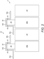
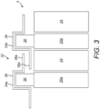
- Figures 2 and 3 show a first embodiment of the heat shields 34a, 34b.
- the first heat shield 34a has a base part 39 having the shape of an inverted U and fins 36a, 38a which extend axially outwardly from the inverted opposed sides of the base part 39.
- the base part 39 may extend over a portion of the outer periphery of the radially outer portion 30 of the rotor disc 20a, 20b.
- a first fin 36a therefore extends from a first side 40 of the radially outer portion 30 and a second fin 38b extends from an opposite second side 42 of the radially outer portion 30.
- the second heat shield 34b has generally the same fin arrangement as the first heat shield 34a.
- Like numbers indicate like parts.
- the second fin 38a of the first heat shield 34a and the first fin 36a of the second heat shield 34b extend towards each other into the gap 32.
- the first and second heat shields 34a, 34b are configured and arranged such that they will not come into contact during use of the braking system 4 as the rotor and/or stator discs 20, 24 wear.
- the respective fins 36a, 38a of the first and second heat shields 34a, 34b are arranged at different radial distances from the axis A-A such that the fins 36a, 38a are able to overlap axially during use of the braking system 4 as the rotor discs 20a, 20b and/or stator discs 24 wear.
- Figure 2 schematically illustrates the braking system 4 in an unworn configuration, where the rotor discs 20a, 20b and stator discs 24 have a maximum thickness.
- the first heat shield 34a and the second heat shield 34b extend into the gap 32 towards each other, but do not overlap or overlap to just a small degree.
- Figure 3 shows the braking system of Figures 2 in a worn configuration. In this configuration, the first heat shield 34a and the second heat shield 34b axially overlap or overlap to a greater degree.
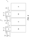
- Figures 4 and 5 show a second embodiment of the heat shields 34a, 34b, which differs only from the embodiment of Figures 2 and 3 in the arrangement of fins.
- Figure 4 shows the braking system 4 in an unworn configuration
- Figure 5 shows the braking system 4 in a worn configuration.
- the first heat shield 34a has three axially extending fins 36a, 36b, 38a.
- Two first fins 36a, 36b extend from the first side 40 of the radially outer portion 30 and a second fin 38a extends from the opposite second side 42 of the radially outer portion 30.
- the second heat shield 34b has generally the same fin arrangement as the first heat shield 34a.
- Like numbers indicate like parts.
- the second fin 38a of the first heat shield 34a and the first fins 36a, 36b of the second heat shield 34b extend towards each other into the gap 32.
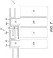
- Figures 6 and 7 show a third embodiment of the heat shields 34a, 34b, which again differs only from the embodiment of Figures 2 and 3 in the arrangement of fins.
- Figure 6 shows the braking system 4 in an unworn configuration
- Figure 7 shows the braking system 4 in a worn configuration.
- the first heat shield 34a has four axially extending fins 36a, 36b, 38a, 38b.
- Two first fins 36a, 36b extend from the first side 40 of the radially outer portion 30 and two second fins 38a, 38b extend from the opposite second side 42 of the radially outer portion 30.
- the second heat shield 34b has generally the same fin arrangement as the first heat shield 34a.
- Like numbers indicate like parts.
- the second fins 38a, 38b of the first heat shield 34a and the first fins 36a, 36b of the second heat shield 34b extend towards each other into and/or over the gap 32.
- the two first fins 36a, 36b extend into the gap.
- the radially inner second fin 38a also extends into the gap.
- the radially outer second fin 38b extends over the gap 32. In other embodiments, all of the fins 36a, 36b, 38a, 38b may extend into the gap 32.
- Figures 8 and 9 show a fourth embodiment of the disclosure. This embodiment differs from the embodiment of Figures 2 and 3 in the arrangement of fins and in that the fins do not overlap in the worn configuration.
- Figure 8 shows the braking system 4 in an unworn configuration and
- Figure 9 shows the braking system 4 in a worn configuration.
- This embodiment is illustrated on a braking system 4 having four rotor discs 20a, 20b, 20c, 20d.
- the first fin 36a and the second fin 38a project axially from opposed sides of the rotor disc and are arranged at substantially the same radial distance from the wheel axis A-A. However, they have an axial length such that the fins 36a, 38b will not contact each other during use of the braking system 4 as the rotor discs 20a- 20d and stator discs 20 wear, as illustrated in Figure 9 .
- the first fin 36a and the second fin 38a are formed as a single axially extending fin 44 positioned radially outwardly of the radially outer portion 30.
- the fin 44 extends axially from a first side 40 and a second side 42 of the radially outer portion 30.
- the second, third and fourth heat shields 34b, 34c, 34d also have a single axially extending fin 44.
- Like numbers indicate like parts.
- the fins 44 of adjacent heat shields 34a, 34b, 34c, 34d extend towards each other over gaps 32.
- This embodiment may advantageously be simpler to manufacture than the overlapping embodiments described above, although potentially it may not be as effective thermally.
- the second heat shield 34b has the same fin arrangement as the first heat shield 34a. In alternative embodiments, the second heat shield 34b may have a different fin arrangement to the first heat shield 34a.
- the first and/or second heat shield 34a, 34b may have just one axially extending fin extending from one side of the radially outer portion and no fins extending from the opposite side of the radially outer portion. In other embodiments, the first and/or second heat shield 34a, 34b may have a plurality of axially extending fins extending from the same side of the radially outer portion and no fins extending from the opposite side of the radially outer portion.
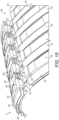
- Figure 10 shows a perspective view of a further exemplary braking system 4.
- the braking system 4 employs a heat shield configuration as illustrated in Figures 6 and 7 mounted to a plurality of rotor discs 20a, 20b, 20c, 20d, 20e in a brake disc stack 28.
- the brake disc stack 28 is shown in the braked position in a worn configuration.
- the radially outer portions 30 of the rotor discs each comprise a plurality of axially extending slots 48.
- the slots 48 are adapted to receive torque bars 22 ( Figure 1 ) for rotationally coupling the rotor discs 20a- 20e to the wheel 2.
- the circumferential side surfaces 50 of the slots 48 receive rotor clips 52 mounted to the rotor discs 20a-20e and adapted to protect the side surfaces 50 of the slots 48.
- the heat shields 34a, 34b, 34c, 34d are mounted to or integrally formed with the rotor clips 52.
- each section 54 has a rotor clip 52 at either end, and the heat shields 34 are mounted to and extend between the rotor clips 52 for substantially the entire length of the section 54.
- the heat shields 34 may be mounted to or integrally formed with the rotor clips 52 at either or both ends of a given section 54.
- a single rotor clip may extend along the length of a circumferential section 54 and the heat shields 34 are mounted to or integrally formed with the single rotor clip.
- Figure 10 illustrates a plurality of identical rotor clips 52 installed on each circumferential section 54 of the radially outer portions 30 of the rotor discs 20a-20e.
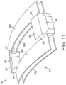
- FIG 11 shows a detailed view of the rotor clips 52.
- the rotor clips 52 are formed from a pair of bodies 56 adapted to protect the side surfaces 50 of the slots 48 and a heat shield 34 extending between the bodies 56. It will be appreciated that a single body 56 may also be used.
- Each body 56 is adapted to mount to a radially outer portion 30 of a brake rotor disc 20a-20e.
- the clip 52 may be riveted to the rotor disc 20.
- Each body 56 has a base 58 and first and second sides 60, 62 extending substantially parallel to each other from opposite ends of the base 58.
- a heat shield 34 integrally formed with the bodies 56. Alternatively, the heat shield 34 may be mounted to the bodies 56.
- the heat shield 34 does not have a separate base part as in the earlier embodiment. It will be appreciated however that the heat shield 34 could have a base part that is integrally formed with the bases 58 of the bodies 56, or that the base part and the base 58 could alternatively be separate parts.
- Figures 10 and 11 may alternatively utilise heat shield configurations as shown in relation to the other embodiments, or as described herein.
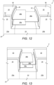
- Figures 12 and 13 show a braking system 4 with rotor clips 52 having a heat shield configuration as illustrated in Figures 4 and 5 .
- Figure 12 shows the brake disc stack 28 in the braked position in an unworn configuration.
- Figure 13 shows the brake disc stack 28 in the braked position in a worn configuration.
- a single rotor clip 52 having a single rotor clip body 56 extends along the length of a circumferential section 54 of the radially outer portions 30.
- the heat shield fins 36a, 36b, 38a are separate parts that are mounted to the first and second sides 60, 62 of the body 56.
- the features and functionality of the braking system 4 of Figures 12 and 13 are otherwise the same as for the braking system 4 described above with reference to Figures 10 and 11 .
- the rotor clip 52 may be formed from any suitable materials.
- the rotor clip body may be formed from a conventional rotor clip material, such as steel.
- the heat shield 34 may be formed from the same material as the body, or a different material with suitable thermal properties.
- the heat shield 34 may be integrally formed with the rotor clip body 56, for example by sheet metal forming. Alternatively, the heat shield 34 may be manufactured as a separate part and connected to the body 56 using any suitable process such as riveting, brazing, or welding.
- the heat shield fins 36a, 36b, 38a, 38b may also be manufactured as separate parts and mounted to the base part 39 of the heat shield 34 and/or the body 56 of the rotor clip 52 using any suitable process such as riveting, brazing, or welding.
- While using a rotor clip 52 is a convenient way of mounting the heat shield to the rotor discs 20, other mechanisms may be used.
- the heat shields may be directly mounted to axially facing surfaces of the rotors or be mounted to saddles which extends over the radially outer portions 30 of the rotor discs 20.
- Simulations were performed to compare the thermal performance of the embodiment illustrated in Figure 10 with a baseline model.
- the baseline model represented a conventional braking system, and included rotor clips (but no heat shields 34).
- the density of the clips 52 with heat shields 34 was decreased so the disclosure model and the baseline model had similar mass. This removed any temperature decreases associated with increased mass from the analysis and allowed a direct comparison of the effect of the geometry of the disclosure model on thermal performance compared with the baseline model.
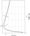
- Figure 14 shows the results of a high energy stop simulation.
- a single high energy stop was simulated to represent braking during a high energy stop.
- Figure 12 shows the temperature of the wheel rim 8 at point B (shown on Figure 1 ) during the simulation.
- the high energy stop standard requires the temperature at point B to remain below a critical temperature (T crit ) for a specified period of time. It is therefore advantageous for the braking system 4 to take as long as possible to reach this temperature during braking simulation.
- Line 70 on Figure 14 shows the thermal performance of the baseline model and line 72 shows the thermal performance of the disclosure model. It can be seen that the disclosure model has a lower maximum temperature (T max ) and also takes longer to reach the maximum temperature (T max ) compared with the baseline model. The disclosure model also takes longer to reach T crit . Therefore, the invention model has improved thermal performance compared with the baseline model in the high energy stop simulation.
Landscapes
- Engineering & Computer Science (AREA)
- General Engineering & Computer Science (AREA)
- Mechanical Engineering (AREA)
- Transportation (AREA)
- Braking Arrangements (AREA)
Abstract
Description
- The present disclosure relates to braking systems for aircraft wheels, and in particular to heat shielding of braking systems.
- Aircraft wheel braking systems dissipate kinetic energy as heat during braking. This is typically achieved by frictional contact between adjacent stationary and rotating brake discs, the rotating brake discs being mounted to rotate with a rotating aircraft wheel. During braking, the brake discs heat up rapidly. It is important for the tyre of the wheel to be shielded from the hot brake discs, as exposure to excessive heat could lead to failure.
- Aircraft braking systems must meet certain standards to achieve certification. Two widely used standards are high energy stop and fuse plug normal stop. Aircraft wheel and brake designers seek to optimise braking system design while meeting the requirements of these standards.
- It is therefore desirable to provide an aircraft braking system with improved heat shielding to improve wheel and brake thermal performance.
- In accordance with a first aspect of the present disclosure, there is provided a braking system for an aircraft wheel. The braking system comprises first and second brake rotor discs axially spaced along an axis and rotationally coupled to the wheel, a stator disc arranged axially between the first and second rotor discs, and a heat shield mounted to at least one of the first and second rotor discs. Radially outer portions of the first and second rotor discs extend radially outwardly of the stator disc to define a gap between the radially outer portions of the first and second rotor discs. The heat shield extends at least partially over or into the gap.
- In embodiments of the disclosure, the heat shield may comprise a first heat shield mounted to the first rotor disc and a second heat shield mounted to the second rotor disc, the first heat shield and the second heat shield both extending at least partially over or into the gap.
- In embodiments of the disclosure, the first and/or second heat shields may comprise at least one axially extending fin. The first heat shield may comprise one, two, three, or four fins. The second heat shield may comprise one, two, three, or four fins.
- In embodiments of the disclosure, the fins may have a curved profile that is substantially concentric with the rotor disc axis.
- In embodiments of the disclosure, the first and second heat shields may be configured and arranged such that they will not come into contact during use of the braking system as the rotor discs and/or stator disc wear.
- In certain embodiments, respective fins of the first and second heat shields may be arranged at different radial distances from the axis such that the fins may overlap axially during use of the braking system as the rotor discs and stator disc wear.
- In alternative arrangements, respective fins of the first and second heat shields may be arranged at substantially the same radial distance but have an axial length such that the fins will not contact each other during use of the braking system as the rotor discs and stator disc wear.
- In embodiments of the disclosure, the radially outer portions of the first and second rotor discs may each comprise a plurality of axially extending slots. The slots may be adapted to receive torque bars for coupling the first and second rotor discs to the wheel. The circumferential side surfaces of the slots may receive rotor clips mounted to the rotor discs and adapted to protect the side surfaces of the slots. The heat shield(s) may be mounted to or integrally formed with the rotor clips.
- In embodiments of the disclosure, each rotor clip may comprise a body adapted to mount to a radially outer portion of the first and/or second brake rotor disc. The body may have a base and first and second sides extending substantially parallel to each other from opposite ends of the base. The heat shield may be mounted to or integrally formed with the body. The heat shield may comprise at least one first fin extending substantially orthogonally from the first side of the body.
- In accordance with a second aspect of the present disclosure, there is provided a rotor clip for an aircraft wheel braking system. The rotor clip comprises a body adapted to mount to a radially outer portion of a brake rotor disc and a heat shield mounted to or integrally formed with the body. The body has a base and first and second sides extending substantially parallel to each other from opposite ends of the base. The heat shield comprises at least one first fin extending substantially orthogonally from the first side of the body.
- In embodiments of the disclosure, the fin(s) may have a curved profile.
- In embodiments of the disclosure, the rotor clip may comprise a plurality of first fins extending from the first side of the body. For example, the rotor clip may comprise two or three first fins.
- In embodiments of the disclosure, the braking system according to the first aspect or the rotor clip according to the second aspect may further comprise at least one second fin extending substantially orthogonally from the second side of the body and extending in an opposite direction to the at least one first fin. In an embodiment, the braking system according to the first aspect or the rotor clip according to the second aspect may comprise a plurality of second fins, for example two or three second fins.
- In certain embodiments, the first fin(s) and the second fin(s) may be arranged at different distances from the base. In alternative embodiments, at least one first fin and a or the at least one second fin may be arranged at substantially the same distance from the base.
- In accordance with a third aspect of the present disclosure, there is provided a method of reducing heat transfer from a brake disc stack to a wheel. The method comprises positioning a heat shield in a gap formed between the radially outer portions of adjacent rotor discs in the stack.
- Some embodiments of the disclosure will now be described by way of example with reference to the accompanying drawings in which;
-
Figure 1 shows a cross-sectional view of an aircraft wheel and a braking system; -
Figure 2 shows, schematically, a first embodiment of a heat shield for a braking system, with the braking system in an unworn configuration; -
Figure 3 shows, schematically, the first embodiment of a heat shield for a braking system, with the braking system in a worn configuration; -
Figure 4 shows, schematically, a second embodiment of a heat shield for a braking system, with the braking system in an unworn configuration; -
Figure 5 shows, schematically, the second embodiment of a heat shield for a braking system, with the braking system in a worn configuration; -
Figure 6 shows, schematically, a third embodiment of a heat shield for a braking system, with the braking system in an unworn configuration; -
Figure 7 shows, schematically, the third embodiment of a heat shield for a braking system, with the braking system in a worn configuration; -
Figure 8 shows, schematically, a fourth embodiment of a heat shield for a braking system, with the braking system in an unworn configuration; -
Figure 9 shows, schematically, the fourth embodiment of a heat shield for a braking system, with the braking system in a worn configuration; -
Figure 10 shows a perspective view of an exemplary braking system utilising the third embodiment heat shield; -
Figure 11 shows a perspective view of a rotor clip for use with the braking system ofFigure 10 ; -
Figure 12 shows a perspective view of another exemplary braking system utilising the second embodiment heat shield, with the braking system in an unworn configuration; -
Figure 13 shows a perspective view the braking system ofFigure 12 , with the braking system in a worn configuration; and -
Figure 14 shows the results of high energy stop simulation for the embodiment ofFigure 10 . -
Figure 1 shows anaircraft wheel 2 and abraking system 4. Thewheel 2 comprises atyre 6 mounted to a wheel rim 8. Thewheel 2 rotates about anaxle 10 viabearings 12. The wheel rim 8 defines acavity 14 for receiving thebraking system 4. Thebraking system 4 is actuated by one ormore pistons 16 mounted to theaxle 10 in any suitable manner, as is known in the art. - A
primary heat shield 18 of conventional design is positioned between thebraking system 4 and thewheel 2 to absorb heat generated in thebraking system 4 during braking and reduce the amount of heat passing into the wheel rim 8 andtyre 6. Due to the restricted space between thebraking system 4 and the wheel rim 8, it is difficult to modify theprimary heat shield 18 to improve thermal performance of thebraking system 4. - The
braking system 4 has a plurality ofbrake rotor discs 20a-20e axially spaced along an axis A-A and rotationally coupled to thewheel 2. In the embodiment shown, thebraking system 4 has fiverotor discs 20a-20e. In other embodiments, thebraking system 4 may have any suitable number of rotor discs. For example, the braking system may have two, three, four, six, or seven rotor discs. - The
brake rotor discs 20a-20e are rotationally coupled to the wheel rim 8 via torque bars 22 such that therotor discs 20a-20e rotate with thewheel 2, but so as to be movable axially relative thereto. - A
respective stator disc 24 is arranged axially between each adjacent pair ofrotor discs 20a-20e.Stator discs 24 are also arranged axially at either end of therotor discs 20a-20e. In the embodiment shown, thebraking system 4 has sixstator discs 24. Thestator discs 24 are arranged between the first andsecond rotor discs third rotor discs fourth rotor discs fifth rotor discs first rotor disc 20a and thelast rotor disc 20e. In other embodiments, thebraking system 4 may have any suitable number ofstator discs 24. For example, thebraking system 4 may have one, two, three, four, five, or sevenstator discs 24. In an embodiment where thebraking system 4 has onerotor disc 20a, thebraking system 4 may havedouble stator discs 24. - The
stator discs 24 are coupled to theaxle 10 via atorque tube 26 or other suitable means such that thestator discs 24 do not rotate relative to theaxle 10, and also do not rotate relative to therotor discs 20a-20e. Thestator discs 24 are, however, moveable axially relative to theaxle 10. - The
rotor discs 20a-20e andstator discs 24 together form abrake disc stack 28. Therotor discs 20a-20e and/or thestator discs 24 may be made from a carbon material or other suitable brake pad material that wears during use of thebraking system 4. The rotor discs 20 and thestator discs 24 may be made from the same or different materials and/or wear at the same or different rates. - In use, the
piston 16 is moved axially under hydraulic pressure of other means to press the rotor discs 20 andstator discs 24 into frictional engagement. As thediscs 20, 24 wear, they will become thinner. As such, the axial spacing between the rotor discs 20 will decrease, and the overall axial length of thestack 28 will decrease. - Radially
outer portions 30 of therotor discs 20a-20e extend radially outwardly of thestator discs 24 to define anaxial gap 32 between the radiallyouter portions 30 ofadjacent rotor discs 20a-20e. As will be discussed further below, in accordance with the disclosure aheat shield 34 is mounted to at least one of therotor discs 20a-20e and extends at least partially over and/or into thegap 32. - Various configurations of the
braking system 4 will now be described with reference toFigures 2 to 9 . Although thebraking system 4 is described by reference to the firstbrake rotor disc 20a and the secondbrake rotor disc 20b, it will be appreciated that the following description also applies to the other adjacent pair ofrotor discs 20a-20e, such as the second andthird rotor discs fourth rotor discs fifth rotor discs - In the various embodiments illustrated, the
heat shield 34 includes afirst heat shield 34a mounted to thefirst rotor disc 20a and asecond heat shield 34b mounted to thesecond rotor disc 20b. In all illustrated embodiments, both thefirst heat shield 34a and thesecond heat shield 34b extend at least partially over and/or into thegap 32 defined between the radiallyouter portions 30 ofadjacent rotor discs heat shield tyre 6. - In each of the embodiments described, the first and
second heat shields fin -
Figures 2 and3 show a first embodiment of theheat shields first heat shield 34a has abase part 39 having the shape of an inverted U andfins base part 39. Thebase part 39 may extend over a portion of the outer periphery of the radiallyouter portion 30 of therotor disc first fin 36a therefore extends from afirst side 40 of the radiallyouter portion 30 and asecond fin 38b extends from an oppositesecond side 42 of the radiallyouter portion 30. Thesecond heat shield 34b has generally the same fin arrangement as thefirst heat shield 34a. Like numbers indicate like parts. Thesecond fin 38a of thefirst heat shield 34a and thefirst fin 36a of thesecond heat shield 34b extend towards each other into thegap 32. - The first and
second heat shields braking system 4 as the rotor and/orstator discs 20, 24 wear. - The
respective fins second heat shields fins braking system 4 as therotor discs stator discs 24 wear. -
Figure 2 schematically illustrates thebraking system 4 in an unworn configuration, where therotor discs stator discs 24 have a maximum thickness. In this configuration, thefirst heat shield 34a and thesecond heat shield 34b extend into thegap 32 towards each other, but do not overlap or overlap to just a small degree. - During use of the
braking system 4, therotor discs stator discs 24 wear, causing the thickness of the rotor and/or stator discs to decrease.Figure 3 shows the braking system ofFigures 2 in a worn configuration. In this configuration, thefirst heat shield 34a and thesecond heat shield 34b axially overlap or overlap to a greater degree. -
Figures 4 and5 show a second embodiment of theheat shields Figures 2 and3 in the arrangement of fins.Figure 4 shows thebraking system 4 in an unworn configuration andFigure 5 shows thebraking system 4 in a worn configuration. In this embodiment, thefirst heat shield 34a has three axially extendingfins first fins first side 40 of the radiallyouter portion 30 and asecond fin 38a extends from the oppositesecond side 42 of the radiallyouter portion 30. Thesecond heat shield 34b has generally the same fin arrangement as thefirst heat shield 34a. Like numbers indicate like parts. Thesecond fin 38a of thefirst heat shield 34a and thefirst fins second heat shield 34b extend towards each other into thegap 32. -
Figures 6 and7 show a third embodiment of theheat shields Figures 2 and3 in the arrangement of fins.Figure 6 shows thebraking system 4 in an unworn configuration andFigure 7 shows thebraking system 4 in a worn configuration. In this embodiment, thefirst heat shield 34a has four axially extendingfins first fins first side 40 of the radiallyouter portion 30 and twosecond fins second side 42 of the radiallyouter portion 30. Thesecond heat shield 34b has generally the same fin arrangement as thefirst heat shield 34a. Like numbers indicate like parts. Thesecond fins first heat shield 34a and thefirst fins second heat shield 34b extend towards each other into and/or over thegap 32. - In the illustrated embodiment, the two
first fins second fin 38a also extends into the gap. The radially outersecond fin 38b extends over thegap 32. In other embodiments, all of thefins gap 32. -
Figures 8 and9 show a fourth embodiment of the disclosure. This embodiment differs from the embodiment ofFigures 2 and3 in the arrangement of fins and in that the fins do not overlap in the worn configuration.Figure 8 shows thebraking system 4 in an unworn configuration andFigure 9 shows thebraking system 4 in a worn configuration. - This embodiment is illustrated on a
braking system 4 having fourrotor discs first fin 36a and thesecond fin 38a project axially from opposed sides of the rotor disc and are arranged at substantially the same radial distance from the wheel axis A-A. However, they have an axial length such that thefins braking system 4 as therotor discs 20a- 20d and stator discs 20 wear, as illustrated inFigure 9 . - In the embodiment shown, the
first fin 36a and thesecond fin 38a are formed as a singleaxially extending fin 44 positioned radially outwardly of the radiallyouter portion 30. Thefin 44 extends axially from afirst side 40 and asecond side 42 of the radiallyouter portion 30. The second, third andfourth heat shields axially extending fin 44. Like numbers indicate like parts. Thefins 44 ofadjacent heat shields gaps 32. - Referring to
Figure 8 , in the unworn configuration, there is agap 46 betweenfins 44 ofadjacent heat shields Figure 9 , in the worn configuration, thegap 46 betweenfins 44 ofadjacent heat shields fins 44 do not contact each other. - This embodiment may advantageously be simpler to manufacture than the overlapping embodiments described above, although potentially it may not be as effective thermally.
- In all of the above embodiments, the
second heat shield 34b has the same fin arrangement as thefirst heat shield 34a. In alternative embodiments, thesecond heat shield 34b may have a different fin arrangement to thefirst heat shield 34a. - In some embodiments (not illustrated), the first and/or
second heat shield second heat shield -
Figure 10 shows a perspective view of a furtherexemplary braking system 4. Thebraking system 4 employs a heat shield configuration as illustrated inFigures 6 and7 mounted to a plurality ofrotor discs brake disc stack 28. Thebrake disc stack 28 is shown in the braked position in a worn configuration. - Referring to
Figure 10 , the radiallyouter portions 30 of the rotor discs each comprise a plurality of axially extendingslots 48. Theslots 48 are adapted to receive torque bars 22 (Figure 1 ) for rotationally coupling therotor discs 20a- 20e to thewheel 2. The circumferential side surfaces 50 of theslots 48 receiverotor clips 52 mounted to therotor discs 20a-20e and adapted to protect the side surfaces 50 of theslots 48. Theheat shields - The
slots 48 divide the radiallyouter portion 30 of arotor disc 20a-20e into a plurality of peripheralcircumferential sections 54. In the embodiment shown, eachsection 54 has arotor clip 52 at either end, and theheat shields 34 are mounted to and extend between the rotor clips 52 for substantially the entire length of thesection 54. Theheat shields 34 may be mounted to or integrally formed with the rotor clips 52 at either or both ends of a givensection 54. In an alternative embodiment, a single rotor clip may extend along the length of acircumferential section 54 and theheat shields 34 are mounted to or integrally formed with the single rotor clip. -
Figure 10 illustrates a plurality of identical rotor clips 52 installed on eachcircumferential section 54 of the radiallyouter portions 30 of therotor discs 20a-20e. -
Figure 11 shows a detailed view of the rotor clips 52. The rotor clips 52 are formed from a pair ofbodies 56 adapted to protect the side surfaces 50 of theslots 48 and aheat shield 34 extending between thebodies 56. It will be appreciated that asingle body 56 may also be used. Eachbody 56 is adapted to mount to a radiallyouter portion 30 of abrake rotor disc 20a-20e. For example, theclip 52 may be riveted to the rotor disc 20. Eachbody 56 has abase 58 and first andsecond sides base 58. Aheat shield 34 integrally formed with thebodies 56. Alternatively, theheat shield 34 may be mounted to thebodies 56. In the embodiment shown, theheat shield 34 does not have a separate base part as in the earlier embodiment. It will be appreciated however that theheat shield 34 could have a base part that is integrally formed with thebases 58 of thebodies 56, or that the base part and the base 58 could alternatively be separate parts. - Although illustrated with a heat shield configuration as shown in
Figures 6 and7 , the embodiment ofFigures 10 and11 may alternatively utilise heat shield configurations as shown in relation to the other embodiments, or as described herein. - For example,
Figures 12 and 13 show abraking system 4 withrotor clips 52 having a heat shield configuration as illustrated inFigures 4 and5 .Figure 12 shows thebrake disc stack 28 in the braked position in an unworn configuration.Figure 13 shows thebrake disc stack 28 in the braked position in a worn configuration. Asingle rotor clip 52 having a singlerotor clip body 56 extends along the length of acircumferential section 54 of the radiallyouter portions 30. Theheat shield fins second sides body 56. The features and functionality of thebraking system 4 ofFigures 12 and 13 are otherwise the same as for thebraking system 4 described above with reference toFigures 10 and11 . - The
rotor clip 52 may be formed from any suitable materials. The rotor clip body may be formed from a conventional rotor clip material, such as steel. Theheat shield 34 may be formed from the same material as the body, or a different material with suitable thermal properties. - Any suitable manufacturing process may be used to form the
rotor clip 52 andheat shield 34. Theheat shield 34 may be integrally formed with therotor clip body 56, for example by sheet metal forming. Alternatively, theheat shield 34 may be manufactured as a separate part and connected to thebody 56 using any suitable process such as riveting, brazing, or welding. Theheat shield fins base part 39 of theheat shield 34 and/or thebody 56 of therotor clip 52 using any suitable process such as riveting, brazing, or welding. - While using a
rotor clip 52 is a convenient way of mounting the heat shield to the rotor discs 20, other mechanisms may be used. For example the heat shields may be directly mounted to axially facing surfaces of the rotors or be mounted to saddles which extends over the radiallyouter portions 30 of the rotor discs 20. - By providing heat shields as described in the embodiments above, heat transfer to the
wheel 2 and thetyre 6 may be reduced. - Simulations were performed to compare the thermal performance of the embodiment illustrated in
Figure 10 with a baseline model. The baseline model represented a conventional braking system, and included rotor clips (but no heat shields 34). For the disclosure model, the density of theclips 52 withheat shields 34 was decreased so the disclosure model and the baseline model had similar mass. This removed any temperature decreases associated with increased mass from the analysis and allowed a direct comparison of the effect of the geometry of the disclosure model on thermal performance compared with the baseline model. -
Figure 14 shows the results of a high energy stop simulation. In this simulation a single high energy stop was simulated to represent braking during a high energy stop.Figure 12 shows the temperature of the wheel rim 8 at point B (shown onFigure 1 ) during the simulation. The high energy stop standard requires the temperature at point B to remain below a critical temperature (Tcrit) for a specified period of time. It is therefore advantageous for thebraking system 4 to take as long as possible to reach this temperature during braking simulation. -
Line 70 onFigure 14 shows the thermal performance of the baseline model andline 72 shows the thermal performance of the disclosure model. It can be seen that the disclosure model has a lower maximum temperature (Tmax) and also takes longer to reach the maximum temperature (Tmax) compared with the baseline model. The disclosure model also takes longer to reach Tcrit. Therefore, the invention model has improved thermal performance compared with the baseline model in the high energy stop simulation. - It will be appreciated that the above embodiments are exemplary only and that modifications thereto may be made within the scope of the disclosure.
Claims (14)
- A braking system (4) for an aircraft wheel (2), comprising:first and second brake rotor discs (20a, 20b) axially spaced along an axis (A) and rotationally coupled to the wheel (2);a stator disc (24) arranged axially between the first and second rotor discs (20a, 20b), wherein radially outer portions (30) of the first and second rotor discs (20a, 20b) extend radially outwardly of the stator disc (24) to define a gap (32) between the radially outer portions (30) of the first and second rotor discs (20a, 20b); anda heat shield (34) mounted to at least one of the first and second rotor discs (20a, 20b) and extending at least partially over or into the gap (32), wherein:the heat shield (34) comprises a first heat shield (34a) mounted to the first rotor disc (20a) and a second heat shield (34b) mounted to the second rotor disc (20b), the first heat shield (34a) and the second heat shield (34b) both extending at least partially over or into the gap (32);the first and/or second heat shields (34a, 34b) comprise at least one axially extending fin (36a, 38a); andrespective fins (36a, 38a) of the first and second heat shields (34a, 34b) are arranged at substantially the same radial distance but have an axial length such that the fins (36a, 38a) will not contact each other during use of the braking system as the rotor discs (20) and stator disc (24) wear.
- A braking system as claimed in claim 1 wherein the first heat shield (34a) comprises one, two, three, or four fins.
- A braking system as claimed in claims 1 or 2, wherein the second heat shield (34b) comprises one, two, three, or four fins.
- A braking system as claimed in any preceding claim, wherein the fins (36, 38) have a curved profile that is substantially concentric with the rotor disc axis (A).
- A braking system as claimed in any preceding claim, wherein the radially outer portions (30) of the first and second rotor discs (20a, 20b) each comprise a plurality of axially extending slots (48), the slots (48) adapted to receive torque bars (22) for coupling the first and second rotor discs (20a, 20b) to the wheel (2), the circumferential side surfaces (50) of the slots (48) receiving rotor clips (52) mounted to the rotor discs (20a, 20b) and adapted to protect the side surfaces (50) of the slots (48), and the heat shield(s) (34a, 34b) is/are mounted to or integrally formed with the rotor clips (52).
- A braking system as claimed in claim 5, wherein each rotor clip (52) comprises a body (56) adapted to mount to a radially outer portion (30) of the first and/or second brake rotor disc (20a, 20b), the body (56) having a base (58) and first and second sides (60, 62) extending substantially parallel to each other from opposite ends of the base (58), and the heat shield (34a, 34b) is mounted to or integrally formed with the body (56), the heat shield comprising at least one first fin (36, 38) extending substantially orthogonally from the first side (60) of the body (56).
- A rotor clip (52) for an aircraft wheel braking system, comprising:a body (56) adapted to mount to a radially outer portion (30) of a brake rotor disc (20a, 20b), the body (56) having a base (58) and first and second sides (60, 62) extending substantially parallel to each other from opposite ends of the base (58);a heat shield (34) mounted to or integrally formed with the body (56), the heat shield (34) comprising at least one first fin (36, 38) extending substantially orthogonally from the first side (60) of the body (58).
- A rotor clip as claimed in claim 7, wherein the fin(s) (36, 38) has/have a curved profile.
- A braking system as claimed in claim 6 or a rotor clip as claimed in claim 7 or 8, wherein the rotor clip (52) comprises a plurality of first fins (36a) extending from the first side (60) of the body (58), for example two or three first fins (36a).
- A braking system as claimed in claim 6 or 9 or a rotor clip as claimed in any of claims 7 to 9, further comprising at least one second fin (38a), the at least one second fin (38a) extending substantially orthogonally from the second side (62) of the body (58) and extending in an opposite direction to the at least one first fin (38a).
- A braking system or rotor clip as claimed in claim 10, wherein the at least one second fin (38a) comprises a plurality of second fins (38a), for example two or three second fins (38a).
- A braking system or a rotor clip as claimed in any of claims 9 to 11, wherein the first fin(s) (36a) and the second fin(s) (38b) are arranged at different distances from the base (58).
- A braking system or a rotor clip as claimed in any of claims 9 to 11, wherein at least one first fin (36a) and a or the at least one second fin (38b) are arranged at substantially the same distance from the base (58).
- A method of reducing heat transfer from a brake disc stack (28) to a wheel (2) comprising positioning a heat shield (34) in a gap (32) formed between the radially outer portions (30) of adjacent rotor discs (20a, 20b) in the stack (28).
Priority Applications (1)
| Application Number | Priority Date | Filing Date | Title |
|---|---|---|---|
| EP23157862.6A EP4215423B1 (en) | 2019-06-21 | 2019-06-21 | Braking system for an aircraft wheel |
Applications Claiming Priority (2)
| Application Number | Priority Date | Filing Date | Title |
|---|---|---|---|
| EP19461545.6A EP3753793B1 (en) | 2019-06-21 | 2019-06-21 | Braking system for an aircraft wheel |
| EP23157862.6A EP4215423B1 (en) | 2019-06-21 | 2019-06-21 | Braking system for an aircraft wheel |
Related Parent Applications (1)
| Application Number | Title | Priority Date | Filing Date |
|---|---|---|---|
| EP19461545.6A Division EP3753793B1 (en) | 2019-06-21 | 2019-06-21 | Braking system for an aircraft wheel |
Publications (2)
| Publication Number | Publication Date |
|---|---|
| EP4215423A1 true EP4215423A1 (en) | 2023-07-26 |
| EP4215423B1 EP4215423B1 (en) | 2026-04-15 |
Family
ID=67001734
Family Applications (2)
| Application Number | Title | Priority Date | Filing Date |
|---|---|---|---|
| EP19461545.6A Active EP3753793B1 (en) | 2019-06-21 | 2019-06-21 | Braking system for an aircraft wheel |
| EP23157862.6A Active EP4215423B1 (en) | 2019-06-21 | 2019-06-21 | Braking system for an aircraft wheel |
Family Applications Before (1)
| Application Number | Title | Priority Date | Filing Date |
|---|---|---|---|
| EP19461545.6A Active EP3753793B1 (en) | 2019-06-21 | 2019-06-21 | Braking system for an aircraft wheel |
Country Status (2)
| Country | Link |
|---|---|
| US (1) | US11274716B2 (en) |
| EP (2) | EP3753793B1 (en) |
Families Citing this family (4)
| Publication number | Priority date | Publication date | Assignee | Title |
|---|---|---|---|---|
| US20210283958A1 (en) * | 2020-03-13 | 2021-09-16 | Goodrich Corporation | Wheel assembly with exterior fuse plug |
| US11320010B2 (en) * | 2020-04-02 | 2022-05-03 | Honeywell International Inc. | Braking system |
| EP4155571B1 (en) * | 2021-09-24 | 2024-08-14 | Goodrich Corporation | Heat shield panel attachment bracket |
| EP4403790B1 (en) * | 2023-01-18 | 2026-03-25 | Goodrich Corporation | Heat shield assembly |
Citations (8)
| Publication number | Priority date | Publication date | Assignee | Title |
|---|---|---|---|---|
| FR2212007A5 (en) * | 1972-12-21 | 1974-07-19 | Dunlop Ltd | |
| DE2505177A1 (en) * | 1974-02-08 | 1975-08-14 | Dunlop Ltd | CONSTRUCTION OF WHEEL AND DISC BRAKE |
| US3958833A (en) * | 1974-10-29 | 1976-05-25 | The Bendix Corporation | Heat shield and drive key apparatus for disc brake |
| US4084857A (en) * | 1976-12-20 | 1978-04-18 | The Bendix Corporation | Drive key heat shield and support for wheel rim heat shield of multiple disc brake |
| US4856619A (en) * | 1988-06-06 | 1989-08-15 | Loral Corporation | Aircraft wheel drive key and heatshield assembly |
| GB2284027A (en) * | 1993-11-05 | 1995-05-24 | Dunlop Ltd | Multi-disc brake |
| WO2008097386A2 (en) * | 2006-10-23 | 2008-08-14 | Goodrich Corporation | Segmented heat shield assembly |
| US20180031062A1 (en) * | 2016-07-27 | 2018-02-01 | Safran Landing Systems | Heat screen with obstacles for a braked aircraft wheel |
Family Cites Families (31)
| Publication number | Priority date | Publication date | Assignee | Title |
|---|---|---|---|---|
| US3051528A (en) * | 1960-08-15 | 1962-08-28 | Bendix Corp | Segmented heat shield for wheels |
| US3972395A (en) * | 1974-03-29 | 1976-08-03 | The Bendix Corporation | Oxidation inhibiting caps for carbon friction disc |
| US4007814A (en) * | 1976-02-05 | 1977-02-15 | Goodyear Aerospace Corporation | Carbon brake disk with cast keyslot reinforcement members |
| US4017123A (en) * | 1976-04-02 | 1977-04-12 | The Bendix Corporation | Dual layer heat shield for wheels |
| US4249642A (en) * | 1978-11-06 | 1981-02-10 | The Bendix Corporation | Oxidation inhibiting cap for a carbon friction disc |
| US4511021A (en) * | 1983-04-21 | 1985-04-16 | The B. F. Goodrich Company | Brake apparatus |
| FR2581148B1 (en) * | 1985-04-26 | 1987-06-19 | Messier Hispano Sa | THERMAL PROTECTION DISC BRAKE FOR VEHICLE WHEELS, ESPECIALLY FOR AIRCRAFT. |
| US4784246A (en) * | 1987-02-18 | 1988-11-15 | The B. F. Goodrich Company | Brake apparatus |
| FR2629888B1 (en) * | 1988-04-08 | 1991-02-22 | Messier Hispano Sa | CARBON BRAKE ROTOR DISC EQUIPPED WITH REINFORCEMENT RIDERS |
| US5002342A (en) * | 1989-12-28 | 1991-03-26 | Aircraft Braking Systems Corporation | Brake assembly heat shield |
| US5236249A (en) * | 1991-08-07 | 1993-08-17 | Allied-Signal Inc. | Wheel assembly hinged heat shield |
| US5310025A (en) * | 1992-07-23 | 1994-05-10 | Allied-Signal Inc. | Aircraft brake vibration damper |
| GB9220603D0 (en) * | 1992-09-30 | 1992-11-11 | Dunlop Ltd | Toughened carbon composite brake discs |
| FR2719879B1 (en) * | 1994-05-11 | 1996-06-07 | Messier Bugatti | Reinforcement device for carbon brake discs, and brake disc equipped with such devices. |
| US5851056A (en) * | 1996-06-03 | 1998-12-22 | The B. F. Goodrich Company | Aircraft brake heat shield having easily removed heat shield sections |
| US6419056B1 (en) * | 1998-10-29 | 2002-07-16 | Aircraft Braking Systems Corp. | Apparatus for aircraft brake thermal management |
| GB2369659A (en) * | 2000-12-01 | 2002-06-05 | Federal Mogul Brake Syst Ltd | Mounting a brake disc |
| US6514041B1 (en) * | 2001-09-12 | 2003-02-04 | Alstom (Switzerland) Ltd | Carrier for guide vane and heat shield segment |
| US7051845B2 (en) * | 2001-10-10 | 2006-05-30 | Goodrich Corporation | Heat shield assembly for aircraft wheel and brake assembly |
| US7303055B2 (en) * | 2004-04-15 | 2007-12-04 | Goodrich Corporation | Method and apparatus for protecting a friction brake disc |
| EP1917420A1 (en) * | 2005-08-23 | 2008-05-07 | ALSTOM Technology Ltd | Device for securing installation of and fixing a heat shield element for a rotor unit of a flow engine |
| US8776955B2 (en) * | 2007-02-02 | 2014-07-15 | Warner Electric Technology Llc | Liquid cooled brake with support columns |
| US7802758B2 (en) * | 2007-05-04 | 2010-09-28 | Honeywell International Inc. | Load-distributing rotor insert for aircraft brakes |
| US9103393B2 (en) | 2012-07-18 | 2015-08-11 | Goodrich Corporation | Systems and methods for heat shield assemblies |
| US10100670B2 (en) * | 2013-06-14 | 2018-10-16 | United Technologies Corporation | Heatshield assembly with double lap joint for a gas turbine engine |
| US9315261B2 (en) * | 2013-06-26 | 2016-04-19 | Goodrich Corporation | Keyed brake disk assembly |
| US20160279710A1 (en) * | 2015-03-25 | 2016-09-29 | Goodrich Corporation | Aircraft brake rotor clip repair methods |
| US9718317B2 (en) * | 2015-10-15 | 2017-08-01 | Goodrich Corporation | Short trapezoidal wheel gasket |
| US9908375B2 (en) * | 2015-10-20 | 2018-03-06 | Goodrich Corporation | Ventilated key-slot full circle heat shield |
| US10221905B2 (en) * | 2016-11-09 | 2019-03-05 | Goodrich Corporation | Bridged clip retainer for brake system |
| FR3072648B1 (en) | 2017-10-23 | 2021-11-12 | Safran Landing Systems | AIRCRAFT BRAKED WHEEL SHIM |
-
2019
- 2019-06-21 EP EP19461545.6A patent/EP3753793B1/en active Active
- 2019-06-21 EP EP23157862.6A patent/EP4215423B1/en active Active
- 2019-12-11 US US16/711,188 patent/US11274716B2/en active Active
Patent Citations (8)
| Publication number | Priority date | Publication date | Assignee | Title |
|---|---|---|---|---|
| FR2212007A5 (en) * | 1972-12-21 | 1974-07-19 | Dunlop Ltd | |
| DE2505177A1 (en) * | 1974-02-08 | 1975-08-14 | Dunlop Ltd | CONSTRUCTION OF WHEEL AND DISC BRAKE |
| US3958833A (en) * | 1974-10-29 | 1976-05-25 | The Bendix Corporation | Heat shield and drive key apparatus for disc brake |
| US4084857A (en) * | 1976-12-20 | 1978-04-18 | The Bendix Corporation | Drive key heat shield and support for wheel rim heat shield of multiple disc brake |
| US4856619A (en) * | 1988-06-06 | 1989-08-15 | Loral Corporation | Aircraft wheel drive key and heatshield assembly |
| GB2284027A (en) * | 1993-11-05 | 1995-05-24 | Dunlop Ltd | Multi-disc brake |
| WO2008097386A2 (en) * | 2006-10-23 | 2008-08-14 | Goodrich Corporation | Segmented heat shield assembly |
| US20180031062A1 (en) * | 2016-07-27 | 2018-02-01 | Safran Landing Systems | Heat screen with obstacles for a braked aircraft wheel |
Also Published As
| Publication number | Publication date |
|---|---|
| EP4215423B1 (en) | 2026-04-15 |
| US11274716B2 (en) | 2022-03-15 |
| US20200400204A1 (en) | 2020-12-24 |
| EP3753793B1 (en) | 2023-02-22 |
| EP3753793A1 (en) | 2020-12-23 |
Similar Documents
| Publication | Publication Date | Title |
|---|---|---|
| US11274716B2 (en) | Braking system for an aircraft wheel | |
| EP3084256B1 (en) | Ventilated brake disc | |
| EP1395761B1 (en) | A disk-brake disk with air cooling | |
| EP2503176B1 (en) | Heat shield installation for aircraft wheel to improve convective cooling of aircraft brake | |
| US5850895A (en) | Metallic aircraft brake disk having thermal relief slots | |
| US10989260B2 (en) | Air cooling of disc brake unit by longitudinal vortex generator | |
| EP3440373B1 (en) | Brake disc with coning-compensating arrangement | |
| EP2749785B1 (en) | Brake disk assembly | |
| EP3752751B1 (en) | Braking band of a disc for a disc brake of the ventilated type | |
| US3892293A (en) | Disc brakes | |
| JPS6124839A (en) | Disc brake and assembling method thereof | |
| JP7090024B2 (en) | Heat shield element | |
| GB2144186A (en) | Disc for disc brake | |
| WO2013043634A1 (en) | Composite rotor | |
| TWI701396B (en) | Disc brakes for railway vehicles and disc brakes for railway vehicles | |
| US20230303240A1 (en) | Wheel and brake assembly | |
| KR101994113B1 (en) | Vented Brake Disc | |
| US20220042564A1 (en) | Braking band of a disc for disc brake of ventilated type | |
| JP7364211B2 (en) | brake rotor | |
| JPH07167177A (en) | Additional structure for improving pressure distribution on disk for aircraft brake | |
| CA3017394C (en) | Brake disc with coning-compensating arrangement | |
| JP6351415B2 (en) | Braking member | |
| JP6115089B2 (en) | Disc brake pad |
Legal Events
| Date | Code | Title | Description |
|---|---|---|---|
| PUAI | Public reference made under article 153(3) epc to a published international application that has entered the european phase |
Free format text: ORIGINAL CODE: 0009012 |
|
| STAA | Information on the status of an ep patent application or granted ep patent |
Free format text: STATUS: THE APPLICATION HAS BEEN PUBLISHED |
|
| AC | Divisional application: reference to earlier application |
Ref document number: 3753793 Country of ref document: EP Kind code of ref document: P |
|
| AK | Designated contracting states |
Kind code of ref document: A1 Designated state(s): AL AT BE BG CH CY CZ DE DK EE ES FI FR GB GR HR HU IE IS IT LI LT LU LV MC MK MT NL NO PL PT RO RS SE SI SK SM TR |
|
| STAA | Information on the status of an ep patent application or granted ep patent |
Free format text: STATUS: REQUEST FOR EXAMINATION WAS MADE |
|
| 17P | Request for examination filed |
Effective date: 20240126 |
|
| RBV | Designated contracting states (corrected) |
Designated state(s): AL AT BE BG CH CY CZ DE DK EE ES FI FR GB GR HR HU IE IS IT LI LT LU LV MC MK MT NL NO PL PT RO RS SE SI SK SM TR |
|
| STAA | Information on the status of an ep patent application or granted ep patent |
Free format text: STATUS: EXAMINATION IS IN PROGRESS |
|
| 17Q | First examination report despatched |
Effective date: 20250213 |
|
| GRAP | Despatch of communication of intention to grant a patent |
Free format text: ORIGINAL CODE: EPIDOSNIGR1 |
|
| STAA | Information on the status of an ep patent application or granted ep patent |
Free format text: STATUS: GRANT OF PATENT IS INTENDED |
|
| INTG | Intention to grant announced |
Effective date: 20251106 |
|
| GRAS | Grant fee paid |
Free format text: ORIGINAL CODE: EPIDOSNIGR3 |
|
| GRAA | (expected) grant |
Free format text: ORIGINAL CODE: 0009210 |
|
| STAA | Information on the status of an ep patent application or granted ep patent |
Free format text: STATUS: THE PATENT HAS BEEN GRANTED |
|
| AC | Divisional application: reference to earlier application |
Ref document number: 3753793 Country of ref document: EP Kind code of ref document: P |
|
| AK | Designated contracting states |
Kind code of ref document: B1 Designated state(s): AL AT BE BG CH CY CZ DE DK EE ES FI FR GB GR HR HU IE IS IT LI LT LU LV MC MK MT NL NO PL PT RO RS SE SI SK SM TR |
|
| REG | Reference to a national code |
Ref country code: CH Ref legal event code: F10 Free format text: ST27 STATUS EVENT CODE: U-0-0-F10-F00 (AS PROVIDED BY THE NATIONAL OFFICE) Effective date: 20260415 |
|
| REG | Reference to a national code |
Ref country code: DE Ref legal event code: R096 Ref document number: 602019083819 Country of ref document: DE |