EP4215420A1 - Four-point seat belt and relative road vehicle - Google Patents
Four-point seat belt and relative road vehicle Download PDFInfo
- Publication number
- EP4215420A1 EP4215420A1 EP23151950.5A EP23151950A EP4215420A1 EP 4215420 A1 EP4215420 A1 EP 4215420A1 EP 23151950 A EP23151950 A EP 23151950A EP 4215420 A1 EP4215420 A1 EP 4215420A1
- Authority
- EP
- European Patent Office
- Prior art keywords
- seat belt
- damping
- seams
- seam
- user
- Prior art date
- Legal status (The legal status is an assumption and is not a legal conclusion. Google has not performed a legal analysis and makes no representation as to the accuracy of the status listed.)
- Pending
Links
Images


Classifications
-
- B—PERFORMING OPERATIONS; TRANSPORTING
- B60—VEHICLES IN GENERAL
- B60R—VEHICLES, VEHICLE FITTINGS, OR VEHICLE PARTS, NOT OTHERWISE PROVIDED FOR
- B60R22/00—Safety belts or body harnesses in vehicles
- B60R22/12—Construction of belts or harnesses
- B60R22/16—Construction of belts or harnesses using belts which become permanently deformed, i.e. one time use
-
- B—PERFORMING OPERATIONS; TRANSPORTING
- B60—VEHICLES IN GENERAL
- B60R—VEHICLES, VEHICLE FITTINGS, OR VEHICLE PARTS, NOT OTHERWISE PROVIDED FOR
- B60R22/00—Safety belts or body harnesses in vehicles
- B60R22/02—Semi-passive restraint systems, e.g. systems applied or removed automatically but not both ; Manual restraint systems
-
- B—PERFORMING OPERATIONS; TRANSPORTING
- B60—VEHICLES IN GENERAL
- B60R—VEHICLES, VEHICLE FITTINGS, OR VEHICLE PARTS, NOT OTHERWISE PROVIDED FOR
- B60R22/00—Safety belts or body harnesses in vehicles
- B60R22/12—Construction of belts or harnesses
-
- B—PERFORMING OPERATIONS; TRANSPORTING
- B60—VEHICLES IN GENERAL
- B60R—VEHICLES, VEHICLE FITTINGS, OR VEHICLE PARTS, NOT OTHERWISE PROVIDED FOR
- B60R22/00—Safety belts or body harnesses in vehicles
- B60R22/02—Semi-passive restraint systems, e.g. systems applied or removed automatically but not both ; Manual restraint systems
- B60R2022/027—Four-point seat belt systems, e.g. with the two upper points connected together
-
- B—PERFORMING OPERATIONS; TRANSPORTING
- B60—VEHICLES IN GENERAL
- B60R—VEHICLES, VEHICLE FITTINGS, OR VEHICLE PARTS, NOT OTHERWISE PROVIDED FOR
- B60R22/00—Safety belts or body harnesses in vehicles
- B60R22/28—Safety belts or body harnesses in vehicles incorporating energy-absorbing devices
- B60R2022/283—Safety belts or body harnesses in vehicles incorporating energy-absorbing devices using tearing or scoring of material
-
- B—PERFORMING OPERATIONS; TRANSPORTING
- B60—VEHICLES IN GENERAL
- B60R—VEHICLES, VEHICLE FITTINGS, OR VEHICLE PARTS, NOT OTHERWISE PROVIDED FOR
- B60R22/00—Safety belts or body harnesses in vehicles
- B60R22/28—Safety belts or body harnesses in vehicles incorporating energy-absorbing devices
- B60R2022/289—Energy-absorption curves
Definitions
- the present invention relates to a four-point seat belt and to a relative road vehicle.
- the present invention is advantageously but not exclusively applied to a high-performance road vehicle provided with four-point seat belts, to which the following description explicitly refers, without thereby losing generality.
- each of these branches comprises a fixed portion and a portion adjustable by the user depending on the body features and on the preferences of said user (i.e. how much the user wants the seat belt to clench him/her) .
- the above-mentioned four-point seat belts are closed (hooked) by means of a centrally arranged buckle.
- the adjustable portions of the shoulder straps are usually sewn at intermediate points of the adjustable portions of the waist bands, so as to allow a quick closing of the buckle by simply coupling the two waist bands.
- the above-mentioned four-point seat belts anchor the back of the user in an integral manner to the seat accommodating him/her; in other words, the four-point seat belts do not allow a deviation of the chest or of the waist of the user as the common three-point seat belts, which enable the driver to change position on the seat or inclination based on his/her preferences, by virtue of the fact that the vehicular dynamics are mild.
- the integral anchoring of the trunk of the user to the seat determines risks in case of crashes or accidents, since, in the case for example of front impact, the only part of the body of the user not anchored, i.e. the head, is entirely subjected to the (negative) acceleration due to the impact and is thrusted forward without control, risking to cause injuries, faints (which can be lethal in the case when the vehicle catches fire after the accident), etc..
- the object of the present invention is to provide a four-point seat belt and a relative road vehicle which are at least partially exempt from the above-described drawbacks and, simultaneously, are simple and cost-effective to manufacture.
- a four-point seat belt and a relative road vehicle are provided according to what claimed in the following independent claims and, preferably, in any one of the claims directly or indirectly dependent on the independent claims.
- reference numeral 1 indicates, as a whole, a road vehicle provided with two front wheels 2 and with two rear wheels (in particular driving wheels).
- the vehicle 1 is provided with a passenger compartment 3 which is adapted to house one or more users U, such as the driver DR and one or more passengers PG as is illustrated in Figure 1 .
- second component does not imply the presence of a “first” component.
- Such terms in fact, are used as labels for improving the clarity and are not to be understood in a limiting manner.
- the vehicle 1 further comprises at least one seat 4, in particular a seat 4 for each user U to be housed inside the passenger compartment 3.
- the vehicle 1 comprises at least one 4-point seat belt 5, in particular a seat belt 5 for each seat 4; in the case of a two-seat road vehicle as the one illustrated in Figure 1 , the road vehicle 1 comprises a four-point seat belt for the driver DR and a four-point seat belt 5 for the passenger PG.
- the seat belt 5 comprises two thoracic branches 6 configured to anchor (during the normal use, in an integral manner) the chest C of the user U to a backrest 7 of the vehicular seat 4.
- the seat belt 5 comprises two abdominal branches 8 configured to girdle and anchor the waist of the user to a seat (of known type and not illustrated) of the vehicular seat 4.
- the thoracic branches 6 and the abdominal branches 8 are substantially formed starting from bands of fabric of known type and therefore not more specified in the following (i.e. wefts comprising polymers, for example polyester).
- the thoracic branches 6 comprise a fixed portion 9 and a portion 10 adjustable by the user U, respectively, for making the seat belt 5 adhere.
- the abdominal branches 8 comprise a fixed portion 11 and a portion 12 adjustable by the user U, respectively, for making the seat belt 5 adhere.
- the thoracic branches 6 and the abdominal branches 8 centrally converge at a same buckle 13 configured to be arranged in the centre of the (sub)abdominal of the user U.
- the right and left thoracic branches 6 converge towards respective connecting elements 14 with the right and left abdominal branches 8.
- each fixed portion 9, 11 is arranged in a distal position with respect to the buckle 13, whereas each adjustable position 10, 12 is arranged between the buckle 13 and the respective fixed portion 9, 11 to which it is connected by means of an adjusting element 15, which in turn is coupled in an integral manner to the fixed portion 9, 11, and in an adjustable manner (sliding) to the adjustable portion 10, 12. Therefore, in particular, the user U can adjust the seat belt 5 by pulling respective edges 16 of each adjustable portion 10, 12 (in particular coming out of the adjusting element 15).
- the thoracic branches 6 and the abdominal branches 8 each comprise an end 17, which is configured to be mechanically coupled to a portion of vehicular frame (or integral with it) by means of fixing means 18 (of known type and not more specified).
- the ends 17 are comprised in the fixed portion 9, 11 of the respective thoracic 6 and abdominal 8 branches.
- the thoracic branches 6 connect the fixing means 18 to the adjusting element 15 by means of a band (of fabric) seamlessly.
- the seat belt 5 comprises at least one damping device 19, which is configured to be activated upon exceeding a first predetermined value TS' of a tension force F ( Figures 3-5 ) imparted by the user U to the seat belt 5 (in particular to the fixed portion 9 of each thoracic branch 6).
- the damping device is configured to cause (generate), upon its activation, a controlled advancement of the chest C of the user U while limiting the acceleration of the head H of said user U.
- the damping device 19 is configured to cause a controlled advancement of the chest by extending (i.e. increasing the length) a portion 20 of the seat belt with an extension stroke E from 30 mm to 300 mm, in particular from 50 mm to 150 mm, more in particular of 100 mm.
- la seat belt 5 comprises two damping devices 19, each of which is arranged along the fixed portion 9 of each of the thoracic branches 6.
- the damping devices 19 are arranged in a part of the fixed portion 9, which preferably is not in contact with the user U (in other words, the portion 20 is not in contact with the user U).
- the damping devices 19 are arranged behind the seat 4 (i.e. behind the backrest 7).
- the damping devices 19 are arranged at a distance less than 300 mm (preferably less than 200 mm, in particular less than 100 mm) from the end 17 or from the fixing means 18.
- each damping device 19 comprises one or more damping seams 21, which are configured to break or unravel (in a controlled manner) upon the activation of said damping device 19.
- the unravelling or the breaking of such seams 21 enables gradually making the chest C of the user U advance, reducing the stresses on the head H.
- the damping seams 21 are made directly on the band (i.e. on the fabric) which defines the thoracic branch 6.
- the damping device 19 comprises a fold 22 of the fixed portion 9 of the respective thoracic branch 6.
- the fold 22 is made as a U.
- the band of fabric which defines the thoracic branch 6 is U-folded on itself, forming a buffer which enables the extension of the thoracic branch 6 upon the activation of the damping device 19.
- the U-fold 22 is unfolded.
- the branches of the U forming the fold 22 are spaced apart from each other, making the portion 20 rectilinear. This allows avoiding having to introduce metal buckles which could break or deform in an uncontrolled manner during the damping and damage the driver DR.
- the damping device 19 does not comprise any metal element. This allows avoiding manufacturing defects or melting of the metal which could compromise the safety of the driver DR during an accident.
- the fold 22 comprises two branches having identical length equal to half of the above-mentioned extension E.
- the fold 22 is made so as to project from the fixed portion 9 and direct the concavity downwards during the damping. In other non-limiting cases not illustrated, the fold 22 is made so as to project from the fixed portion 9 and direct the concavity upwards during the damping.
- the damping device 19 comprises an activation seam 23 arranged at an end 24 of the damping seam 21 and configured to break or unravel upon reaching the first predetermined value TS'.
- the seams 21 are made so as to have respective longitudinal axes AX substantially parallel to a longitudinal axis A of the thoracic branch 6 on which the damping device 19 is located.
- the activation seam 23 is arranged transversally to the axis A of the thoracic branch 6.
- the activation seat belt 23 is arranged perpendicularly to the axis A. More in particular, the activation seam 23 extends for most of (substantially the totality of, or anyway so as to be in contact with all the damping seams 21) the width of the thoracic branch 6.
- the activation seam 23 connects the damping seams 21 to each other.
- the damping seams 21 have the ends 24 substantially aligned. In other words, the damping seams 21 converge, on the side of the ends 24, in the activation seam 23.
- the activation seam 23 is made so as to allow the breaking/unravelling of the damping seams 21 only after the activation seam 23 has been in turn broken or unravelled by the force F.
- the damping device 19 comprises a sacrificial seam 25, which is made so as to maintain the thoracic branches 6 substantially with a planar configuration.
- the planar configuration is maintained by folding into S shape the portion 20 of the seat belt 5, preferably further folding on itself the U-shaped fold 22.
- it is possible to reduce the bulks for example facilitating the insertion of the branches 6 in the specially provided holes or housings which are often pre-arranged in the seats 4.
- the sacrificial seam 25 is arranged transversally to the axis A of the thoracic branch 6.
- the sacrificial seat belt 25 is arranged perpendicularly to the axis A. More precisely the sacrificial seam 25 is counterposed to the activation seam 23 with respect to the damping seams 21.
- the sacrificial seam 25 is configured to direct the fold 22 towards the user U.
- the sacrificial seam 25 is configured to break or unravel upon reaching a second predetermined value TS" of the tension force F.
- the second value TS" is lower than the first predetermined value TS'.
- the sacrificial seam 25 is the first to yield (unravels or tears) (see Figure 4 )
- the activation seam 23 is the second to yield (unravels or tears) followed by the damping seams 21 (see Figures 5 and 6 ).
- the one or more damping seams 21 have a zigzag structure. In such manner, it is possible to increase the length of a continuous seam 21, which can gradually unravel occupying less space.
- the damping seams 21 comprise a plurality of bridges 28 comprised between 5 mm and 13 mm.
- the step of the sacrificial seam 25 is less than 10 mm, in particular less than 5 mm, preferably 2.5 mm.
- each damping seam 21 comprises at least twenty, in particular at least thirty, preferably at least forty bridges 28.
- the damping device 19 comprises a plurality of damping seams 21 arranged parallel to each other.
- the parallel damping seams 21 are configured to be activated by means of the transverse activation seam 23 which connects the respective ends 24 thereof.
- the activation seam 23 is made with one or more sections along the same row, in particular starting from an initial outer point 26 and ending with a final inner point 27, i.e. arranged along an intermediate portion between the ends of the activation seam 23.
- the damping seams 21 and the activation seam 23 are made by means of a single continuous seam.
- the damping seams 21 are made starting from the end 24 carrying out a rectilinear section and re-travelling the narrow zig zag section, progressively making (while moving from one damping seam 21 to the other) the activation seam 23.
- the activation seam 23 has a length which ranges from 20 mm to 60 mm, in particular from 30 mm to 50 mm, more in particular from 38 mm to 43 mm.
- the damping device 19 comprises at least five, in particular six, parallel damping seams 21.
- damping seams 21 and/or the activation seam 23 and/or the sacrificial seam 25 are made by coupling to each other two different yarns (inserted, as is known and thus not more specified in the following, by means of needle and reel).
- a first yarn used for making the damping seams 21 (and/or the activation seam 23 and/or the sacrificial seam 25) is an interweaved yarn (preferably Nyflex).
- interweaved yarn comprises between two and five yarns having a metric figure from 15 to 30, in particular from 18 to 25.
- it is an Nm 20/3 yarn, i.e. obtained by interweaving between each other three yarns with metric figure Nm equal to 20.
- a second type of yarn used for making the damping seams 21 (and/or the activation seam 23 and/or the sacrificial seam 25) is a single yarn (preferably Nyster) having a metric figure comprised between 80 and 150, more precisely between 110 and 130, specifically 125.
- the above-mentioned values relative to the yarns were obtained empirically so as to maximise repeatability and acceptability of the load according to the laws in force (ECE) .
- the damping 21 and/or activation 23 and/or sacrificial 25 seams are made by means of yarns (or compositions of yarns) different from each other.
- the sacrificial seam 25 is made by means of a single yarn (preferably Nyster) having a metric figure comprised between 80 and 150, more precisely between 110 and 130, specifically 125.
- a single yarn preferably Nyster
- the first predetermined value TS' ranges from 1 kN to 5 kN, in particular from 1.5 kN to 3.5 kN.
- the activation seam 23 is made so as to yield upon the reaching of such loads; for example, in the case where there is a deceleration which generates a tension force F greater than 2kN, the activation seam 23 yields activating the unravelling/breaking of the damping seams 21.
- the one or more damping seams 21 are configured to break or unravel at an average load AL which ranges from 1 kN to 3 kN, in particular from 1.5 kN to 2.5 kN. In such manner, the breaking/unravelling of the bridges 28 is gradual, allowing reducing the dynamic load at the head H of the users U.
- the second predetermined value TS" ranges from 0.8 kN to 2.5 kN, in particular from 1 kN to 2 kN.
- the zone Z (illustrated specifically in Figures 3 to 6 ) preferably passes from a resting folded planar configuration ( Figure 3 ), wherein the portion 20 is folded twice on itself, i.e. folded into S-shape, and all the seams 21, 23 and 25 are intact, at an extended configuration (still planar) such as the one of Figure 6 , wherein the seams 21, 23 and 25 are broken or unravelled (passing in particular by the intermediate configurations of Figures 4 and 5 wherein only the sacrificial seam 25 is unravelled/broken respectively and wherein the sacrificial seam 25, the activation seam 23 and part of the damping seams 21 are unravelled/broken).
- step I indicates (with a peak/step) the tension force F which causes the sacrificial seam 25 to break once the value TS" has been reached;
- step II characterised by a peak greater than the one of step I indicates the variation of the tension force F upon the reaching of the heat TS', in particular the peak is given at the breaking/unravelling of the activation seam 23, to which a lessening of the force F follows which tends to the average load AL during step III, i.e. while the damping seams progressively yield. Therefore, the three steps I, II, III subsequent to each other are characterised by two peaks (in steps I and II) upon the yielding of the seams 25 and 23 and by a plateau (in step III) upon the progressive yielding of the damping seams 21.
- the seat belt 5 comprises further two damping devices 19 arranged at the abdominal branches 8 according to what described in the foregoing for the thoracic branches 6.
- the present invention has many advantages.
- the present invention allows optimising the collocation space of the fold thanks to the sacrificial seam.
- the present invention also allows limiting the crushing of the ribs of the user in case of accident, reducing the risk of breaking the same.
Landscapes
- Engineering & Computer Science (AREA)
- Mechanical Engineering (AREA)
- Textile Engineering (AREA)
- Automotive Seat Belt Assembly (AREA)
Abstract
Description
- This patent application claims priority from
Italian patent application no. 102022000000785 filed on January 19, 2022 - The present invention relates to a four-point seat belt and to a relative road vehicle.
- In particular, the present invention is advantageously but not exclusively applied to a high-performance road vehicle provided with four-point seat belts, to which the following description explicitly refers, without thereby losing generality.
- Generally, road vehicles are provided with passive safety systems of different type. One of said passive safety systems, particularly widespread and mandatory in most of the world, is the seat belt.
- Historically, in highly performing vehicles, such as for example cars designed both for the normal road use, and for running on track maximising the performances, four-point seat belts are used, i.e. configured to anchor the user (the passenger or the driver) to the frame of the vehicle by means of four different branches or bands (usually two thoracic branches or shoulder straps and two abdominal or waist branches). Generally, each of these branches comprises a fixed portion and a portion adjustable by the user depending on the body features and on the preferences of said user (i.e. how much the user wants the seat belt to clench him/her) .
- The above-mentioned four-point seat belts are closed (hooked) by means of a centrally arranged buckle. In particular, the adjustable portions of the shoulder straps are usually sewn at intermediate points of the adjustable portions of the waist bands, so as to allow a quick closing of the buckle by simply coupling the two waist bands.
- Because of the strong dynamics to which highly performing vehicles are subject while travelling on track, in order to keep the driver steady in the driving position, the above-mentioned four-point seat belts, unlike the three-point seat belts of common use in road vehicles, anchor the back of the user in an integral manner to the seat accommodating him/her; in other words, the four-point seat belts do not allow a deviation of the chest or of the waist of the user as the common three-point seat belts, which enable the driver to change position on the seat or inclination based on his/her preferences, by virtue of the fact that the vehicular dynamics are mild. On the other hand, the use of bands with elastic adaptation such as that of the three-point seat belts of common cars would determine an uncontrolled movement of the user during the strong longitudinal and lateral accelerations due to the above-mentioned dynamics, i.e. during the normal operation of the vehicle, compromising the performances thereof.
- The integral anchoring of the trunk of the user to the seat, however necessary in terms of performance, determines risks in case of crashes or accidents, since, in the case for example of front impact, the only part of the body of the user not anchored, i.e. the head, is entirely subjected to the (negative) acceleration due to the impact and is thrusted forward without control, risking to cause injuries, faints (which can be lethal in the case when the vehicle catches fire after the accident), etc..
- The object of the present invention is to provide a four-point seat belt and a relative road vehicle which are at least partially exempt from the above-described drawbacks and, simultaneously, are simple and cost-effective to manufacture.
- According to the present invention, a four-point seat belt and a relative road vehicle are provided according to what claimed in the following independent claims and, preferably, in any one of the claims directly or indirectly dependent on the independent claims.
- The claims describe preferred embodiments of the present invention forming integral part of the present description.
- The present invention will now be described with reference to the accompanying drawings, which illustrate some non-limiting example embodiments thereof, wherein:
-
Figure 1 is a perspective and schematic view, with details removed for clarity, of a front portion of a road vehicle in accordance with the present invention through a windshield; -
Figure 2 is a perspective and schematic view, with details removed for clarity, of an embodiment of a four-point seat belt in accordance with the present invention; -
Figures 3 to 6 are perspective and schematic views, with details removed for clarity, of a portion of the seat belt ofFigure 2 in different operating configurations; -
Figure 7 is a bottom schematic view of the seat belt portion ofFigure 3 ; and -
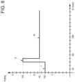
Figure 8 illustrates a graph which shows the tension variation with respect to the extension of a portion of the part of the seat belt in the steps of the sequence ofFigures 4 to 6 . - In
Figure 1 ,reference numeral 1 indicates, as a whole, a road vehicle provided with twofront wheels 2 and with two rear wheels (in particular driving wheels). Thevehicle 1 is provided with apassenger compartment 3 which is adapted to house one or more users U, such as the driver DR and one or more passengers PG as is illustrated inFigure 1 . - The same reference numerals and the same reference letters in the figures identify the same elements or components with the same function.
- Within the scope of the present description, the term "second" component does not imply the presence of a "first" component. Such terms, in fact, are used as labels for improving the clarity and are not to be understood in a limiting manner.
- The elements and the features illustrated in the different preferred embodiments, including the drawings, can be combined with each other without thereby departing from the scope of protection of the present application as described in the following.
- The
vehicle 1 further comprises at least oneseat 4, in particular aseat 4 for each user U to be housed inside thepassenger compartment 3. - Advantageously, as is illustrated in the non-limiting embodiments of
Figures 1 and2 , thevehicle 1 comprises at least one 4-point seat belt 5, in particular aseat belt 5 for eachseat 4; in the case of a two-seat road vehicle as the one illustrated inFigure 1 , theroad vehicle 1 comprises a four-point seat belt for the driver DR and a four-point seat belt 5 for the passenger PG. - As is illustrated in the non-limiting embodiments of
Figures 1 and2 , theseat belt 5 comprises twothoracic branches 6 configured to anchor (during the normal use, in an integral manner) the chest C of the user U to abackrest 7 of thevehicular seat 4. - Furthermore, the
seat belt 5 comprises twoabdominal branches 8 configured to girdle and anchor the waist of the user to a seat (of known type and not illustrated) of thevehicular seat 4. - In particular, the
thoracic branches 6 and theabdominal branches 8 are substantially formed starting from bands of fabric of known type and therefore not more specified in the following (i.e. wefts comprising polymers, for example polyester). - As is illustrated in the non-limiting embodiment of
Figure 2 , advantageously but not necessarily, thethoracic branches 6 comprise a fixedportion 9 and aportion 10 adjustable by the user U, respectively, for making theseat belt 5 adhere. - As is illustrated in the non-limiting embodiment of
Figure 2 , advantageously but not necessarily, theabdominal branches 8 comprise a fixedportion 11 and aportion 12 adjustable by the user U, respectively, for making theseat belt 5 adhere. - Advantageously but not necessarily, the
thoracic branches 6 and theabdominal branches 8 centrally converge at asame buckle 13 configured to be arranged in the centre of the (sub)abdominal of the user U. In particular, in order to facilitate the closing and the opening of theseat belt 5, the right and leftthoracic branches 6 converge towards respective connectingelements 14 with the right and leftabdominal branches 8. - Preferably but not necessarily, each fixed
portion buckle 13, whereas eachadjustable position buckle 13 and the respective fixedportion element 15, which in turn is coupled in an integral manner to the fixedportion adjustable portion seat belt 5 by pullingrespective edges 16 of eachadjustable portion 10, 12 (in particular coming out of the adjusting element 15). - Advantageously but not necessarily, the
thoracic branches 6 and theabdominal branches 8 each comprise anend 17, which is configured to be mechanically coupled to a portion of vehicular frame (or integral with it) by means of fixing means 18 (of known type and not more specified). - Preferably, as is illustrated in the non-limiting embodiment of
Figure 2 , theends 17 are comprised in the fixedportion respective thoracic 6 and abdominal 8 branches. - In particular, the
thoracic branches 6 connect the fixing means 18 to the adjustingelement 15 by means of a band (of fabric) seamlessly. - Advantageously, the
seat belt 5 comprises at least onedamping device 19, which is configured to be activated upon exceeding a first predetermined value TS' of a tension force F (Figures 3-5 ) imparted by the user U to the seat belt 5 (in particular to thefixed portion 9 of each thoracic branch 6). In particular, the damping device is configured to cause (generate), upon its activation, a controlled advancement of the chest C of the user U while limiting the acceleration of the head H of said user U. - According to some preferred non-limiting embodiments such as the ones illustrated in
Figures 3 to 7 , thedamping device 19 is configured to cause a controlled advancement of the chest by extending (i.e. increasing the length) aportion 20 of the seat belt with an extension stroke E from 30 mm to 300 mm, in particular from 50 mm to 150 mm, more in particular of 100 mm. - Advantageously but not necessarily,
la seat belt 5 comprises twodamping devices 19, each of which is arranged along the fixedportion 9 of each of thethoracic branches 6. In particular, thedamping devices 19 are arranged in a part of thefixed portion 9, which preferably is not in contact with the user U (in other words, theportion 20 is not in contact with the user U). In some non-limiting cases, thedamping devices 19 are arranged behind the seat 4 (i.e. behind the backrest 7). - Specifically, the
damping devices 19 are arranged at a distance less than 300 mm (preferably less than 200 mm, in particular less than 100 mm) from theend 17 or from thefixing means 18. - Advantageously but not necessarily, and as is illustrated in the non-limiting embodiments of
Figures 4 to 7 , eachdamping device 19 comprises one ormore damping seams 21, which are configured to break or unravel (in a controlled manner) upon the activation of saiddamping device 19. In such manner, the unravelling or the breaking ofsuch seams 21 enables gradually making the chest C of the user U advance, reducing the stresses on the head H. In particular, thedamping seams 21 are made directly on the band (i.e. on the fabric) which defines thethoracic branch 6. - Advantageously but not necessarily, at the
portion 20, thedamping device 19 comprises afold 22 of thefixed portion 9 of the respectivethoracic branch 6. Preferably, thefold 22 is made as a U. In other words, at theportion 20, the band of fabric which defines thethoracic branch 6 is U-folded on itself, forming a buffer which enables the extension of thethoracic branch 6 upon the activation of thedamping device 19. - Preferably, during the damping, the U-fold 22 is unfolded. In other words, the branches of the U forming the
fold 22 are spaced apart from each other, making theportion 20 rectilinear. This allows avoiding having to introduce metal buckles which could break or deform in an uncontrolled manner during the damping and damage the driver DR. - In particular, the
damping device 19 does not comprise any metal element. This allows avoiding manufacturing defects or melting of the metal which could compromise the safety of the driver DR during an accident. - In particular, the
fold 22 comprises two branches having identical length equal to half of the above-mentioned extension E. - In some non-limiting cases, as the one illustrated in
Figures 4 and5 , thefold 22 is made so as to project from the fixedportion 9 and direct the concavity downwards during the damping. In other non-limiting cases not illustrated, thefold 22 is made so as to project from the fixedportion 9 and direct the concavity upwards during the damping. - According to some preferred but non-limiting embodiments, such as the one illustrated in
Figure 7 , the dampingdevice 19 comprises anactivation seam 23 arranged at anend 24 of the dampingseam 21 and configured to break or unravel upon reaching the first predetermined value TS'. - In some non-limiting cases, such as the ones illustrated in
Figures 2 to 7 , theseams 21 are made so as to have respective longitudinal axes AX substantially parallel to a longitudinal axis A of thethoracic branch 6 on which the dampingdevice 19 is located. - Advantageously but not necessarily, the
activation seam 23 is arranged transversally to the axis A of thethoracic branch 6. In particular, theactivation seat belt 23 is arranged perpendicularly to the axis A. More in particular, theactivation seam 23 extends for most of (substantially the totality of, or anyway so as to be in contact with all the damping seams 21) the width of thethoracic branch 6. - In some preferred non-limiting cases, the
activation seam 23 connects the dampingseams 21 to each other. In the non-limiting embodiment ofFigure 7 , the dampingseams 21 have theends 24 substantially aligned. In other words, the dampingseams 21 converge, on the side of theends 24, in theactivation seam 23. - In particular, the
activation seam 23 is made so as to allow the breaking/unravelling of the dampingseams 21 only after theactivation seam 23 has been in turn broken or unravelled by the force F. - Advantageously but not necessarily, the damping
device 19 comprises asacrificial seam 25, which is made so as to maintain thethoracic branches 6 substantially with a planar configuration. In particular, the planar configuration is maintained by folding into S shape theportion 20 of theseat belt 5, preferably further folding on itself theU-shaped fold 22. In such manner it is possible to reduce the bulks, for example facilitating the insertion of thebranches 6 in the specially provided holes or housings which are often pre-arranged in theseats 4. Furthermore, in such manner there is no risk of inadvertently ruining theactivation seam 23, giving the possibility to visually and quickly verify the integrity of the dampingdevice 19. - Advantageously but not necessarily, the
sacrificial seam 25 is arranged transversally to the axis A of thethoracic branch 6. In particular, thesacrificial seat belt 25 is arranged perpendicularly to the axis A. More precisely thesacrificial seam 25 is counterposed to theactivation seam 23 with respect to the damping seams 21. - Preferably but not limitedly, the
sacrificial seam 25 is configured to direct thefold 22 towards the user U. - According to some preferred but non-limiting embodiments such as the one illustrated in
Figure 7 , thesacrificial seam 25 is configured to break or unravel upon reaching a second predetermined value TS" of the tension force F. In particular, the second value TS" is lower than the first predetermined value TS'. In such manner, upon the increase of the load and thus of the tension force F of the seat belt 5 (for example due to an accident), thesacrificial seam 25 is the first to yield (unravels or tears) (seeFigure 4 ), theactivation seam 23 is the second to yield (unravels or tears) followed by the damping seams 21 (seeFigures 5 and6 ). - According to some non-limiting embodiments, such as the one illustrated in
Figure 7 , the one or more dampingseams 21 have a zigzag structure. In such manner, it is possible to increase the length of acontinuous seam 21, which can gradually unravel occupying less space. - Advantageously but not necessarily, the damping
seams 21 comprise a plurality ofbridges 28 comprised between 5 mm and 13 mm. - Advantageously but not necessarily, the step of the
sacrificial seam 25 is less than 10 mm, in particular less than 5 mm, preferably 2.5 mm. - In some preferred non-limiting cases, each damping
seam 21 comprises at least twenty, in particular at least thirty, preferably at least fortybridges 28. - Preferably, therefore, the damping
device 19 comprises a plurality of dampingseams 21 arranged parallel to each other. In particular, in accordance with what mentioned in the foregoing, the parallel dampingseams 21 are configured to be activated by means of thetransverse activation seam 23 which connects the respective ends 24 thereof. - Advantageously but not necessarily, the
activation seam 23 is made with one or more sections along the same row, in particular starting from an initialouter point 26 and ending with a finalinner point 27, i.e. arranged along an intermediate portion between the ends of theactivation seam 23. - According to some preferred non-limiting embodiments, the damping
seams 21 and theactivation seam 23 are made by means of a single continuous seam. In particular, not limitedly, the dampingseams 21 are made starting from theend 24 carrying out a rectilinear section and re-travelling the narrow zig zag section, progressively making (while moving from one dampingseam 21 to the other) theactivation seam 23. - Preferably, the
activation seam 23 has a length which ranges from 20 mm to 60 mm, in particular from 30 mm to 50 mm, more in particular from 38 mm to 43 mm. - Advantageously but not necessarily, as is illustrated in the non-limiting embodiment of
Figure 7 , the dampingdevice 19 comprises at least five, in particular six, parallel damping seams 21. - In particular, the damping
seams 21 and/or theactivation seam 23 and/or thesacrificial seam 25 are made by coupling to each other two different yarns (inserted, as is known and thus not more specified in the following, by means of needle and reel). - Advantageously but not necessarily, a first yarn used for making the damping seams 21 (and/or the
activation seam 23 and/or the sacrificial seam 25) is an interweaved yarn (preferably Nyflex). Preferably such interweaved yarn comprises between two and five yarns having a metric figure from 15 to 30, in particular from 18 to 25. Specifically, not limitedly, it is anNm 20/3 yarn, i.e. obtained by interweaving between each other three yarns with metric figure Nm equal to 20. A second type of yarn used for making the damping seams 21 (and/or theactivation seam 23 and/or the sacrificial seam 25) is a single yarn (preferably Nyster) having a metric figure comprised between 80 and 150, more precisely between 110 and 130, specifically 125. The above-mentioned values relative to the yarns were obtained empirically so as to maximise repeatability and acceptability of the load according to the laws in force (ECE) . - In some non-limiting cases, the damping 21 and/or
activation 23 and/or sacrificial 25 seams are made by means of yarns (or compositions of yarns) different from each other. - In particular, preferably but not limitedly, the
sacrificial seam 25 is made by means of a single yarn (preferably Nyster) having a metric figure comprised between 80 and 150, more precisely between 110 and 130, specifically 125. - According to some preferred but non-limiting embodiments such as the one illustrated in
Figure 8 , the first predetermined value TS' ranges from 1 kN to 5 kN, in particular from 1.5 kN to 3.5 kN. In other words, theactivation seam 23 is made so as to yield upon the reaching of such loads; for example, in the case where there is a deceleration which generates a tension force F greater than 2kN, theactivation seam 23 yields activating the unravelling/breaking of the damping seams 21. - Advantageously but not necessarily, the one or more damping
seams 21 are configured to break or unravel at an average load AL which ranges from 1 kN to 3 kN, in particular from 1.5 kN to 2.5 kN. In such manner, the breaking/unravelling of thebridges 28 is gradual, allowing reducing the dynamic load at the head H of the users U. - Alternatively or additionally, the second predetermined value TS" ranges from 0.8 kN to 2.5 kN, in particular from 1 kN to 2 kN.
- Obviously, the precise values of the above-mentioned ranges depend on different side conditions relative each time to the type of considered
vehicle 1. - In use, therefore, in case of accelerations above normal, for example due to an accident, the zone Z (illustrated specifically in
Figures 3 to 6 ) preferably passes from a resting folded planar configuration (Figure 3 ), wherein theportion 20 is folded twice on itself, i.e. folded into S-shape, and all theseams Figure 6 , wherein theseams Figures 4 and5 wherein only thesacrificial seam 25 is unravelled/broken respectively and wherein thesacrificial seam 25, theactivation seam 23 and part of the dampingseams 21 are unravelled/broken). - In the non-limiting embodiment of
Figure 8 a graph is illustrated in which the axis of the abscissae indicates a space S of the extension E in millimetres (for example from a space S=0 that represent the moment prior to an impact of thevehicle 1 in an accident), whereas the axis of the ordinates indicates the tension force F in kN. In particular, it is possible to discern three distinct steps I, II and III: step I indicates (with a peak/step) the tension force F which causes thesacrificial seam 25 to break once the value TS" has been reached; step II (characterised by a peak greater than the one of step I) indicates the variation of the tension force F upon the reaching of the heat TS', in particular the peak is given at the breaking/unravelling of theactivation seam 23, to which a lessening of the force F follows which tends to the average load AL during step III, i.e. while the damping seams progressively yield. Therefore, the three steps I, II, III subsequent to each other are characterised by two peaks (in steps I and II) upon the yielding of theseams - According to some non-limiting embodiments not illustrated, the
seat belt 5 comprises further two dampingdevices 19 arranged at theabdominal branches 8 according to what described in the foregoing for thethoracic branches 6. - Although the above-described invention particularly refers to a very precise example embodiment, it is not to be considered limited to such example embodiment, falling within its scope all the variations, modifications or simplifications covered by the appended claims, such as for example a different type of yarn, a different collocation of the seams, a different type of damping device, a different type of vehicle (for example a two-wheel vehicle or a front-drive vehicle), etc.
- The present invention has many advantages.
- Firstly, it allows protecting the safety of the users in case of accident and/or of extreme stresses simultaneously ensuring the solid anchoring of the traditional four-point seat belts. Therefore, it is possible to maximise the performances without the driver risking injuries or faints due to the abrupt advancement of the head in emergency situations.
- Furthermore, the present invention allows optimising the collocation space of the fold thanks to the sacrificial seam.
- Finally, the present invention also allows limiting the crushing of the ribs of the user in case of accident, reducing the risk of breaking the same.
-
- 1
- road vehicle
- 2
- wheels
- 3
- passenger compartment
- 4
- seat
- 5
- seat belt
- 6
- thoracic branches
- 7
- backrest
- 8
- abdominal branches
- 9
- fixed portion
- 10
- adjustable portion
- 11
- fixed portion
- 12
- adjustable portion
- 13
- buckle
- 14
- connecting element
- 15
- adjusting element
- 16
- edge
- 17
- end
- 18
- fixing means
- 19
- damping device
- 20
- seat belt portion
- 21
- damping seams
- 22
- fold
- 23
- activation seam
- 24
- damping seam end
- 25
- sacrificial seam
- 26
- initial point
- 27
- final point
- 28
- bridges
- A
- thoracic branch axis
- AL
- average load
- AX
- damping seam axis
- C
- chest
- DR
- driver
- E
- extension
- F
- tension force
- I
- first step
- II
- second step
- III
- third step
- PG
- passenger
- TS'
- first threshold value
- TS"
- second threshold value
- U
- user
- Z
- zone
Claims (14)
- Four-point seat belt (5) comprising:- at least two thoracic branches (6) configured to anchor the chest (C) of a user (U) to a backrest (7) of a vehicular seat (4);- at least two abdominal branches (8) configured to girdle and anchor the waist of the user (U) to the vehicular seat (4) ;the seat belt (5) being characterized in that it comprises at least one damping device (19) configured to be activated upon exceeding a first predetermined value (TS') of a tension force (F) imparted by the user (U) to the belt (5); the damping device (19) being configured to cause, upon its activation, a controlled advancement of the chest (C) of the user (U) while limiting the acceleration of the head of the user (U);wherein each damping device (19) comprises one or more damping seams (21), the seams being configured to break or unravel upon the activation of said damping device (19);wherein the one or more damping seams (21) have a zigzag structure.
- Seat belt (5) according to claim 1, wherein the damping device (19) is configured to cause a controlled advancement of the chest (C) by extending a portion (20) of the seat belt (5) with an extension stroke (E) from 30 mm to 300 mm, in particular from 50 mm to 150 mm.
- Seat belt (5) according to any one of the preceding claims, wherein the first predetermined value (TS') ranges from 1 kN to 5 kN, in particular from 1.5 kN to 3.5 kN.
- Seat belt (5) according to any one of the preceding claims, wherein a respective damping device (19) is arranged along a fixed portion (9, 11) of each of the thoracic branches (6).
- Seat belt (5) according to any one of the preceding claims, wherein the one or more damping seams (21) are configured to break or unravel with an average load (AL) from 1 kN to 3 kN, in particular from 1.5 kN to 2.5 kN.
- Seat belt (5) according to any one of the preceding claims, wherein the one or more damping seams (21) are made at a fold (22) of the fixed portion (9, 11) of each of the thoracic branches (6).
- Seat belt (5) according to any one of the preceding claims, wherein the damping device (19) comprises a activation seam (23) arranged at one end of the damping seam (21) and is configured to break or unravel upon reaching the first predetermined value (TS').
- Seat belt (5) according to any one of the preceding claims and comprising a sacrificial seam (25), which is configured to maintain the thoracic branches (6) substantially with a planar configuration and to break or unravel upon reaching a second predetermined value (TS'') of the tension force (F), which is lower than the first predetermined value (TS').
- Seat belt (5) according to claim 8, wherein the second predetermined value (TS") ranges from 0.8 kN to 2.5 kN, in particular from 1 kN to 2 kN.
- Seat belt (5) according to any one of the preceding claims, wherein the damping device (19) comprises a plurality of damping seams (21) arranged parallel to each other.
- Seat belt (5) according to claim 10, wherein the parallel damping seams (21) are configured to be activated by means of a transverse activation seam (23) connecting respective ends thereof.
- Seat belt (5) according to claim 11, wherein the damping device (19) comprises at least five, in particular six, parallel damping seams (21).
- Seat belt (5) according to any one of claims 11 or 12, wherein each damping seam (21) comprises at least twenty, in particular at least thirty, preferably at least forty bridges.
- Road vehicle (1) comprising:- four wheels (2), of which at least one pair of wheels (2) is driven;- at least one seat (4);- at least one four-point seat belt (5) according to any one of the preceding claims configured to anchor a user (U) to the seat (4), wherein the thoracic branches (6) are mechanically connected to at least a first portion (20) of a vehicular frame, and the abdominal branches (8) are connected to at least a second portion (20) of the vehicular frame.
Applications Claiming Priority (1)
| Application Number | Priority Date | Filing Date | Title |
|---|---|---|---|
| IT102022000000785A IT202200000785A1 (en) | 2022-01-19 | 2022-01-19 | FOUR-POINT SEAT BELT AND RELEVANT ROAD VEHICLE |
Publications (1)
| Publication Number | Publication Date |
|---|---|
| EP4215420A1 true EP4215420A1 (en) | 2023-07-26 |
Family
ID=80999766
Family Applications (1)
| Application Number | Title | Priority Date | Filing Date |
|---|---|---|---|
| EP23151950.5A Pending EP4215420A1 (en) | 2022-01-19 | 2023-01-17 | Four-point seat belt and relative road vehicle |
Country Status (3)
| Country | Link |
|---|---|
| US (1) | US11958434B2 (en) |
| EP (1) | EP4215420A1 (en) |
| IT (1) | IT202200000785A1 (en) |
Families Citing this family (2)
| Publication number | Priority date | Publication date | Assignee | Title |
|---|---|---|---|---|
| TWI868817B (en) * | 2023-07-24 | 2025-01-01 | 宏霖工業股份有限公司 | Protection reinforcement device for multi-point seat belt system of transportation vehicles |
| CN117068094A (en) * | 2023-08-03 | 2023-11-17 | 厦门理工学院 | Intelligent restraint systems, safety seats and intelligent restraint methods |
Citations (5)
| Publication number | Priority date | Publication date | Assignee | Title |
|---|---|---|---|---|
| AU517944B2 (en) * | 1977-07-25 | 1981-09-03 | Rainfords Metal Products Pty. Ltd. | Safety restraint |
| GB2211070A (en) * | 1987-10-16 | 1989-06-28 | Schroth Gmbh Carl F | A safety belt system |
| EP1069008A1 (en) * | 1999-07-16 | 2001-01-17 | Pavlos Giannakopoulos | Energy absorption element for safety belts |
| US20130033056A1 (en) * | 2011-08-05 | 2013-02-07 | Tunis Iii George C | Energy absorbing system for blast mitigation of support elements such as suspended seats or stretchers in military vehicles |
| WO2018189396A1 (en) * | 2017-04-13 | 2018-10-18 | Rheinmetall Chempro Gmbh | Shock-absorbing seat having damping members |
Family Cites Families (5)
| Publication number | Priority date | Publication date | Assignee | Title |
|---|---|---|---|---|
| US3444957A (en) * | 1967-12-13 | 1969-05-20 | Rose Mfg Co | Shock absorber for safety belt |
| DE3924149A1 (en) * | 1989-07-21 | 1991-01-31 | Porsche Ag | SEAT BELT SYSTEM, ESPECIALLY FOR MOTOR VEHICLES |
| DE9401314U1 (en) * | 1994-01-26 | 1994-04-07 | Trw Repa Gmbh, 73553 Alfdorf | Seat belt with tear seam |
| WO2017083607A1 (en) * | 2015-11-11 | 2017-05-18 | Indiana Mills & Manufacturing, Inc. | Energy absorbing restraint web assembly including a visual deployment indicator |
| TWI636906B (en) * | 2017-08-31 | 2018-10-01 | 王亮雄 | Multi-point safety belt device |
-
2022
- 2022-01-19 IT IT102022000000785A patent/IT202200000785A1/en unknown
-
2023
- 2023-01-13 US US18/154,103 patent/US11958434B2/en active Active
- 2023-01-17 EP EP23151950.5A patent/EP4215420A1/en active Pending
Patent Citations (5)
| Publication number | Priority date | Publication date | Assignee | Title |
|---|---|---|---|---|
| AU517944B2 (en) * | 1977-07-25 | 1981-09-03 | Rainfords Metal Products Pty. Ltd. | Safety restraint |
| GB2211070A (en) * | 1987-10-16 | 1989-06-28 | Schroth Gmbh Carl F | A safety belt system |
| EP1069008A1 (en) * | 1999-07-16 | 2001-01-17 | Pavlos Giannakopoulos | Energy absorption element for safety belts |
| US20130033056A1 (en) * | 2011-08-05 | 2013-02-07 | Tunis Iii George C | Energy absorbing system for blast mitigation of support elements such as suspended seats or stretchers in military vehicles |
| WO2018189396A1 (en) * | 2017-04-13 | 2018-10-18 | Rheinmetall Chempro Gmbh | Shock-absorbing seat having damping members |
Also Published As
| Publication number | Publication date |
|---|---|
| IT202200000785A1 (en) | 2023-07-19 |
| US11958434B2 (en) | 2024-04-16 |
| US20230226994A1 (en) | 2023-07-20 |
Similar Documents
| Publication | Publication Date | Title |
|---|---|---|
| EP4215420A1 (en) | Four-point seat belt and relative road vehicle | |
| US11021129B2 (en) | Occupant restraint device | |
| US6283500B1 (en) | Air bag for an airbag unit | |
| DE60015191T2 (en) | Front airbag, which is separated from its indentation when inflated | |
| US8657328B2 (en) | Arrangement of an inflatable airbag in an instrument panel comprising a flap connected to the instrument panel by a linear tether | |
| US10618492B2 (en) | Inflatable airbag for protecting a person, and airbag module, vehicle parts and vehicle occupant restraint system having such an airbag | |
| EP3825188B1 (en) | Passenger restraint device | |
| US20080203710A1 (en) | Airbag module | |
| US5758900A (en) | Protection system for a driver of a competition vehicle | |
| KR102638238B1 (en) | passenger restraint device | |
| US20180154858A1 (en) | Inflatable airbag for protecting a person, airbag module, vehicle occupant restraining system comprising such an airbag, and method for producing an inflatable airbag | |
| GB2312877A (en) | Side impact air-bag with tensioned strap | |
| GB2397805A (en) | Air-bag with expansion panel | |
| KR101203366B1 (en) | Slide fastener | |
| EP2017141A2 (en) | Airbag and airbag system | |
| US20150102588A1 (en) | Non-slitted tear seam for mini-wrappers | |
| US8931802B2 (en) | Variable volume airbag | |
| EP1069008A1 (en) | Energy absorption element for safety belts | |
| US20080290635A1 (en) | Continuous side airbag seam | |
| US6568709B2 (en) | Breakaway web stop for seat belts | |
| US7077429B2 (en) | Inflatable cushion with shielded seams | |
| US7309103B2 (en) | Vehicle passenger seat with tear-away upholstery cover | |
| JP4225308B2 (en) | Energy absorption device for vehicle side | |
| US20050044671A1 (en) | Safety belt web adjuster | |
| US20080061620A1 (en) | Seatbelt assembly for improved belt safety and comfort |
Legal Events
| Date | Code | Title | Description |
|---|---|---|---|
| PUAI | Public reference made under article 153(3) epc to a published international application that has entered the european phase |
Free format text: ORIGINAL CODE: 0009012 |
|
| STAA | Information on the status of an ep patent application or granted ep patent |
Free format text: STATUS: THE APPLICATION HAS BEEN PUBLISHED |
|
| AK | Designated contracting states |
Kind code of ref document: A1 Designated state(s): AL AT BE BG CH CY CZ DE DK EE ES FI FR GB GR HR HU IE IS IT LI LT LU LV MC ME MK MT NL NO PL PT RO RS SE SI SK SM TR |
|
| STAA | Information on the status of an ep patent application or granted ep patent |
Free format text: STATUS: REQUEST FOR EXAMINATION WAS MADE |
|
| 17P | Request for examination filed |
Effective date: 20240126 |
|
| RBV | Designated contracting states (corrected) |
Designated state(s): AL AT BE BG CH CY CZ DE DK EE ES FI FR GB GR HR HU IE IS IT LI LT LU LV MC ME MK MT NL NO PL PT RO RS SE SI SK SM TR |
|
| STAA | Information on the status of an ep patent application or granted ep patent |
Free format text: STATUS: EXAMINATION IS IN PROGRESS |
|
| 17Q | First examination report despatched |
Effective date: 20241108 |
|
| GRAP | Despatch of communication of intention to grant a patent |
Free format text: ORIGINAL CODE: EPIDOSNIGR1 |
|
| STAA | Information on the status of an ep patent application or granted ep patent |
Free format text: STATUS: GRANT OF PATENT IS INTENDED |
|
| INTG | Intention to grant announced |
Effective date: 20260107 |
|
| GRAS | Grant fee paid |
Free format text: ORIGINAL CODE: EPIDOSNIGR3 |
|
| GRAA | (expected) grant |
Free format text: ORIGINAL CODE: 0009210 |
|
| STAA | Information on the status of an ep patent application or granted ep patent |
Free format text: STATUS: THE PATENT HAS BEEN GRANTED |