EP4215311A1 - Machine tool, positional information correction method, and positional information correction program - Google Patents
Machine tool, positional information correction method, and positional information correction program Download PDFInfo
- Publication number
- EP4215311A1 EP4215311A1 EP21869431.3A EP21869431A EP4215311A1 EP 4215311 A1 EP4215311 A1 EP 4215311A1 EP 21869431 A EP21869431 A EP 21869431A EP 4215311 A1 EP4215311 A1 EP 4215311A1
- Authority
- EP
- European Patent Office
- Prior art keywords
- position information
- spindle
- movable body
- tool
- cutting edge
- Prior art date
- Legal status (The legal status is an assumption and is not a legal conclusion. Google has not performed a legal analysis and makes no representation as to the accuracy of the status listed.)
- Pending
Links
Images


Classifications
-
- B—PERFORMING OPERATIONS; TRANSPORTING
- B23—MACHINE TOOLS; METAL-WORKING NOT OTHERWISE PROVIDED FOR
- B23Q—DETAILS, COMPONENTS, OR ACCESSORIES FOR MACHINE TOOLS, e.g. ARRANGEMENTS FOR COPYING OR CONTROLLING; MACHINE TOOLS IN GENERAL CHARACTERISED BY THE CONSTRUCTION OF PARTICULAR DETAILS OR COMPONENTS; COMBINATIONS OR ASSOCIATIONS OF METAL-WORKING MACHINES, NOT DIRECTED TO A PARTICULAR RESULT
- B23Q15/00—Automatic control or regulation of feed movement, cutting velocity or position of tool or work
- B23Q15/007—Automatic control or regulation of feed movement, cutting velocity or position of tool or work while the tool acts upon the workpiece
- B23Q15/013—Control or regulation of feed movement
-
- B—PERFORMING OPERATIONS; TRANSPORTING
- B23—MACHINE TOOLS; METAL-WORKING NOT OTHERWISE PROVIDED FOR
- B23Q—DETAILS, COMPONENTS, OR ACCESSORIES FOR MACHINE TOOLS, e.g. ARRANGEMENTS FOR COPYING OR CONTROLLING; MACHINE TOOLS IN GENERAL CHARACTERISED BY THE CONSTRUCTION OF PARTICULAR DETAILS OR COMPONENTS; COMBINATIONS OR ASSOCIATIONS OF METAL-WORKING MACHINES, NOT DIRECTED TO A PARTICULAR RESULT
- B23Q17/00—Arrangements for observing, indicating or measuring on machine tools
- B23Q17/22—Arrangements for observing, indicating or measuring on machine tools for indicating or measuring existing or desired position of tool or work
-
- G—PHYSICS
- G05—CONTROLLING; REGULATING
- G05B—CONTROL OR REGULATING SYSTEMS IN GENERAL; FUNCTIONAL ELEMENTS OF SUCH SYSTEMS; MONITORING OR TESTING ARRANGEMENTS FOR SUCH SYSTEMS OR ELEMENTS
- G05B19/00—Program-control systems
- G05B19/02—Program-control systems electric
- G05B19/18—Numerical control [NC], i.e. automatically operating machines, in particular machine tools, e.g. in a manufacturing environment, so as to execute positioning, movement or co-ordinated operations by means of program data in numerical form
- G05B19/401—Numerical control [NC], i.e. automatically operating machines, in particular machine tools, e.g. in a manufacturing environment, so as to execute positioning, movement or co-ordinated operations by means of program data in numerical form characterised by control arrangements for measuring, e.g. calibration and initialisation, measuring workpiece for machining purposes
Definitions
- the present disclosure relates to a machine tool, a position information correction method and a position information correction program.
- a positional relationship between a workpiece and a tool in a machine tool is automatically measured.
- a machine tool defines a cutting edge position of a tool using a center coordinate of a workpiece measured by a probe as a reference position, based on a positional relationship between the peak of a stylus of a probe for measuring the center coordinate of the workpiece and the cutting edge of the tool.
- Japanese Unexamined Patent Publication No. 2008-200798 Japanese Unexamined Patent Publication No. 2008-200798 that a machine tool defines a cutting edge position of a tool using a center coordinate of a workpiece measured by a probe as a reference position, based on a positional relationship between the peak of a stylus of a probe for measuring the center coordinate of the workpiece and the cutting edge of the tool.
- a machine tool calculates a cutting edge position of a tool with respect to a spindle center axis from a spindle center axis measured by contacting a detector of a sensor mounted on a turret with a workpiece, and a positional relationship between a tool attached to the turret together with the sensor and the sensor.
- the object of a machine tool according to the present disclosure is to precisely measure a positional relationship between a workpiece and a tool.
- a machine tool has a spindle configured to rotatably grip a workpiece, a turret configured to mount a tool for processing the workpieces, a movable body configured to move independently from the spindle and the turret, a contact type sensor configured to move in accordance with a movement of the movable body, and a controller configured to calculate center position information indicating a center position of the spindle based on spindle position information acquired via the sensor moved to the vicinity of the workpiece by moving the movable body, wherein the controller acquires cutting edge position information indicating a position of a cutting edge of the tool via the sensor by moving the movable body, and corrects the cutting edge position information based on the center position information.
- the controller acquires the cutting edge position information by moving the movable body so that the center position of the sensor is conformed to the center axis of the spindle, and contacting the cutting edge of the tool with the sensor by moving the turret.
- the senor has a cylindrical support member, and a detector having a plurality of contacts arranged at the circumferential surface of the support member, and the step for moving the movable body so that the center position of the sensor is conformed to the center axis of the spindle includes a step for moving the movable body so that the center axis of the support member is conformed to the center axis of the spindle.
- the plurality of contacts includes four contacts arranged separated by 90 degrees each at the circumferential surface of the support member, and a distance between the pair of contacts arranged 180 degrees apart included in the four contacts is the same as the diameter of the workpiece.
- the movable body is a rear spindle arranged so as to face the spindle.
- a position information correction method for a machine tool having a spindle configured to rotatably grip a workpiece, a turret configured to mount a tool for processing the workpieces, a movable body configured to move independently from the spindle and the turret, a contact type sensor configured to move in accordance with a movement of the movable body, and a controller configured to calculate center position information indicating a center position of the spindle based on spindle position information acquired via the sensor moved to the vicinity of the workpiece by moving the movable body, executed by the controller and including acquiring cutting edge position information indicating a position of a cutting edge of the tool via the sensor by moving the movable body, and correcting the cutting edge position information based on the center position information.
- a position information correction program for a machine tool having a spindle configured to rotatably grip a workpiece, a turret configured to mount a tool for processing the workpieces, a movable body configured to move independently from the spindle and the turret, a contact type sensor configured to move in accordance with a movement of the movable body, and a controller configured to calculate center position information indicating a center position of the spindle based on spindle position information acquired via the sensor moved to the vicinity of the workpiece by moving the movable body, for causing the controller to execute a process including acquiring cutting edge position information indicating a position of a cutting edge of the tool via the sensor by moving the movable body, and correcting the cutting edge position information based on the center position information.
- a machine tool according to the present disclosure may precisely measure the positional relationship between a workpiece and a tool.
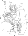
- Fig. 1 is a perspective view of a machine tool according to an embodiment.
- a machine tool 1 has a bed 10, a front spindle 11, a rear spindle 12, a guide bush device 13, a turret 14 and an NC device 20.
- the bed 10 mounts the front spindle 11, rear spindle 12, guide bush device 13 and turret 14.
- the front spindle 11 is a hollow member holding a cylindrical workpiece W1 and may move in a Z1 direction by mounted on a movement mechanism moving along a rail 15.
- the rear spindle 12 is a hollow member holding a cylindrical workpiece W2 and may move in Z2 and X2 directions by mounted on a movement mechanism moving along rails 16 and 17.
- the guide bush device 13 is fixed on the bed 10 and supports the workpiece W1 gripped by the front spindle 11 so as to guide the workpiece W1 slidably in the Z1 direction.
- the turret 14 is a member for holding a plurality of tools for processing the workpieces W1 and W2 gripped by the front and rear spindles 11 and 12, and may move in the X1 and Y1 directions by mounted on movement mechanisms moving long rails 18 and 19.
- the rotation, movement and etc. of the front and rear spindles 11 and 12 and turret 14 are controlled by the NC device 20 mounted on the machine tool 1.
- the front and rear spindles 11 and 12 and turret 14 may move independently of each other, in other words, separately move.
- the NC device 20 is a control device which has a processing circuit, a storage circuit for storing a position correction program for running position information correction processing, and etc., and instructs various operations of the machine tool.
- the position correction program may be installed in a management storage part 42 from for example a CD-ROM, DVD-ROM, or other computer readable portable recording medium using a known setup program.
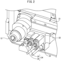
- Fig. 2 is a perspective view of the rear spindle 12 and a front turret 21 arranged adjoining the rear spindle 12.
- the front turret 21 is also referred to as "a facing turret” and is a member holding drills and other rotary tools 22, non-rotary tools 23 and a tool setter 24 and integrally moves along with movement of the rear spindle 12.
- the tool setter 24 is a contact type position sensor having a cylindrical support member 25 and a detector 26 disposed at a circumferential surface of a front end of the support member 25.
- the detector 26 has four contacts arranged separated by 90 degrees each at the circumferential surface of the support member 25, and detects the position of the member from four directions including two directions for each of the X2 and Y2 directions, by contacting the four contacts with the workpiece W1 and etc.
- the tool setter 24 may have four contacts which are contacted the workpiece W1 regardless of whether a distance between a pair of contacts arranged separated by 180 degrees among the four contacts on the detector 26 is smaller or longer than a diameter of the processed workpiece W1. Further, when a distance between a selected pair of contacts is the same as the diameter of the workpiece W1, the workpiece W1 is close to a process point, and therefore it is preferable that the distance therebetween is the same as the diameter of the workpiece W1. When the distance between the pair of contacts is equal to 0.8 time or 0.8 times more than and equal to 1.2 times or 1.2 times less than the diameter of the workpiece W1, it is deemed that the distance therebetween is the same as the diameter thereof.
- Fig. 3 is a flow chart of a position information correction processing performed by the machine tool 1.
- the position information correction processing shown in Fig. 3 is performed by controlling members in the machine tool 1 by instructions from the NC device 20, and coordinated with the members. Further, the position information correction processing shown in Fig. 3 may be performed before the workpiece W1 is processed by tools, and may be suitably performed while the workpiece W1 is processed by the tools. For example, the position information correction processing shown in Fig. 3 may be performed right after the machine tool 1 is started up, may be performed before the processing of the workpiece W1 is started, and may be performed each time a predetermined number of processed workpieces have been formed from the workpiece W1.
- the NC device 20 instructs the front spindle 11 to grip the workpiece W1 (S101).
- the front spindle 11 grips the workpiece W1 by a (not shown) chuck in accordance with the instructions from the NC device 20.
- the NC device 20 instructs acquisition of spindle position information indicating a position of the front spindle (S102).
- Figs. 4A and 4B are views for explaining the processing of S102.
- Fig. 4A is a perspective view of the rear spindle 12 and guide bush device 13
- Fig. 4B is a front view of the guide bush device 13.
- the NC device 20 moves the tool setter 24 to an area near the workpiece W1 supported by the guide bush device 13, by moving the rear spindle 12.
- the NC device 20 acquires spindle position information through the tool setter 24 which is moved to the area near the workpiece W1.
- the NC device 20 contacts the detector 26 of the tool setter 24 with the workpiece W1 as shown in Fig. 4B by an arrow A, and acquires first position information P1 indicating a position of a top end of the workpiece W1 from the tool setter 24.
- the NC device 20 contacts the detector 26 of the tool setter 24 with the workpiece W1 as shown in Fig. 4B by an arrow B, and acquires second position information P2 indicating a position of a left end of the workpiece W1 from the tool setter 24.
- the NC device 20 contacts the detector 26 of the tool setter 24 with the workpiece W1 as shown in Fig.
- the NC device 20 contacts the detector 26 of the tool setter 24 with the workpiece W1 as shown in Fig. 4B by an arrow D, and acquires fourth position information P4 indicating a position of a right end of the workpiece W1 from the tool setter 24. Then, the NC device 20 stores the first position information P1 to the fourth position information P4 acquired through the tool setter 24 as spindle position information.
- NC device 20 calculates center position information indicating a center position of the front spindle 11 based on the spindle position information acquired by the processing of S102 through the tool setter 24 which moves to the area near the workpiece W1 by moving the rear spindle 12.
- the NC device 20 calculates a coordinate Px of the center position of the front spindle 11 in the X1 direction as a center value (P1+P3)/2 of the first position information P1 indicating one coordinate of the workpiece W1 in the X1 direction and the third position information P3 indicating another coordinate of the workpiece W1 in the X1 direction. Further, the NC device 20 calculates the coordinate Py of the center position of the front spindle 11 in the Y1 direction as a center value (P2+P4)/2 of the second position information P2 indicating one coordinate of the workpiece W1 in the Y1 direction and the fourth position information P4 indicating another coordinate of the workpiece W1 in the Y1 direction.
- the NC device 20 instructs the acquisition of cutting edge position information indicating a position of a cutting edge of a tool (S104).
- Figs. 5A and 5B are views for explaining the processing of S104
- Fig. 5A is a perspective view of the rear spindle 12 and guide bush device 13 (part 1)
- Fig. 5B is a perspective view of the rear spindle 12 and guide bush device 13 (part 2).
- the NC device 20 acquires the cutting edge position information by moving the rear spindle 12 so that the center position of the tool setter 24 is conformed to the center axis of the front spindle 11, and moves the turret 14 so that the cutting edge of the tool 140 held by the turret 14 is contacted with the tool setter 24.
- the NC device 20 moves the rear spindle 12 as shown in Fig. 5A , so that the center axis of the support member 25 of the tool setter 24 is conformed to the center axis of the front spindle 11, and the detector 26 of the tool setter 24 comes close to the workpiece W1.
- the NC device 20 moves the rear spindle 12 so that the center of the support member 25 of the tool setter 24 in the X1 direction and Y direction is conformed to the coordinates (Px,Py) indicated by the center position information calculated at the processing of S103.
- the NC device 20 acquires first cutting edge position information K1 indicating a position of a bottom end of the cutting edge from the tool setter 24 by contacting the cutting edge of the tool 140 with the tool setter 24 from one side of the turret 14 in the X1 direction, as shown in Fig. 5A .
- the NC device 20 acquires second cutting edge position information K2 indicating a position of a right end of the cutting edge from the tool setter 24, by contacting the cutting edge of the tool 140 with the tool setter 24 from one side of the turret 14 in the Y1 direction, as shown in Fig. 5B .
- the NC device 20 calculates the coordinates (Kx, Ky) of the cutting edge of the tool 140 in the X1 and Y1 directions, by using the first cutting edge position information K1 and the second cutting edge position information K2.
- the NC device 20 corrects the cutting edge position information acquired by the processing of S104 based on the center position information calculated at the processing of S103 (S105).
- the NC device 20 corrects the coordinates (Kx,Ky) of the cutting edge of the tool 140 in the X1 and Y1 directions by using the coordinates (Px,Py) of the center position of the front spindle 11 in the X1 and Y1 directions included in the center position information as a reference, and generates the corrected coordinates (Cx,Cy).
- Cx is indicated by (Px-Kx)
- Cy is indicated by (Py-Ky).
- the corrected coordinates (Cx,Cy) generated at the processing of S105 indicate the distance between the cutting edge position of the tool 140 and the workpiece W1, and the corrected coordinate Cx, is also referred to as the "diameter", and the corrected coordinate Cy is also referred to as the "core”.
- the position information correction processing is completed.
- the machine tool 1 performs processing of the workpiece W1 by the tool 140 at the tool cutting edge positions corrected based on the position information correction processing.
- the machine tool 1 may correct the positional relationship between the workpiece W1 and tool 140 with a high precision.
- the machine tool 1 may conform the center position of the tool setter 24 to the center axis of the front spindle 11, by conforming the center position of the tool setter 24 to the center axis of the workpiece W1, and the tool setter 24 may come close to the vicinity of the workpiece W1 (processing position).
- the machine tool 1 acquires cutting edge position information indicating a position of the cutting edge of the tool 140 near a position for processing the workpiece W1 in the state where the tool setter 24 is arranged near the workpiece W1, and therefore the machine tool 1 may acquire cutting edge position information with a higher precision than when acquiring cutting edge position information in the state where the tool 140 is far from the workpiece W1.
- the machine tool 1 may calculate center position information indicating a center position of the front spindle 11, then, if a correction amount for a cutting edge position information based on the center position information has been stored in advance, the machine tool 1 uses the correction amount in order to correct the positional relationship between the workpiece W1 and the tool 140. In this case, the machine tool 1 may conform the center axis of the workpiece W1 to the center axis of the tool setter 24.
- the machine tool 1 since the machine tool 1 performs the position information correction processing while the workpiece W1 is processed by the tool 140, the machine tool 1 may correct the positional relationship between the cutting edge of the tool 140 and the workpiece w1 with a high precision even when the cutting edge of the tool 140 is worn. Further, since the machine tool 1 performs the position information correction processing while the workpiece W1 is processed by the tool 140, the machine tool 1 may detect breakage of the cutting edge of the tool 140.
- the cutting edge position information is acquired at a position closer to the position of the tool 140 when the workpiece W1 is processed. Since the distance between the pair of contacts arranged 180 degrees apart included in the detector 26 is the same as the diameter of the workpiece W1, the precision of the cutting edge position information may be further raised.
- tool setter 24 is attached to the front turret 21 which moves along with movement of the rear spindle 12, spindle position information and cutting edge position information are acquired from the workpiece W1 and tool 140 without separately providing members for movement of the tool setter 24.
- the contact type sensor may be held by a movable body which moves the contact type sensor.
- the detector 26 of the tool setter 24 has contacts arranged so as to detect the X1 and Y1 directions
- the detector of the tool setter may also have contacts so as to further detect the Z1 direction.
- the distance between the cutting edge position of the tool 140 and the workpiece W1 may be generated as three-dimensional coordinates including "length” showing the Z1 direction in addition to "diameter” showing the X1 direction and "core” showing the Y1 direction.
- the detector of the tool setter may also have contacts arranged so as to detect either of the X1 direction and Y1 direction.
- the position information correction processing performs the position information correction processing for only the Y1 direction.
- the detector of the tool setter may also have only a single contact. When the detector of the tool setter has only a single contact, the tool setter is arranged so as to circle around the Z1 direction.
- a guide bush device 13 is arranged so as to guide the workpiece W1 by supporting the workpiece W1, the machine tool according to the embodiment need not have the guide bush device 13.
Landscapes
- Engineering & Computer Science (AREA)
- Mechanical Engineering (AREA)
- Human Computer Interaction (AREA)
- Manufacturing & Machinery (AREA)
- Physics & Mathematics (AREA)
- General Physics & Mathematics (AREA)
- Automation & Control Theory (AREA)
- Automatic Control Of Machine Tools (AREA)
- Machine Tool Sensing Apparatuses (AREA)
- Numerical Control (AREA)
Abstract
Description
- The present disclosure relates to a machine tool, a position information correction method and a position information correction program.
- In machine tools including a turning center, machining center and etc., various techniques are known that detect positions of tools for processing workpieces. For example, it is known that a tool is manually contacted with a workpiece, a positional relationship between a cutting edge of the tool and the workpiece is measured, and the position of the tool is input to an NC device as offset. Further, a technique referred to as "external preset" is known that uses a measurement fixture referred to as a "presetter" in order to adjust a position of a tool, and attaches the tool to a tool holder which is attached to a machine tool. However, in these techniques, there have been various problems such that downtime of a machine tool and operator's load are increased.
- To solve the above problems, it is known that a positional relationship between a workpiece and a tool in a machine tool is automatically measured. For example, it is described in
Japanese Unexamined Patent Publication No. 2008-200798 Japanese Unexamined Patent Publication No. 2000-198047 - However, in the techiques described in
Japanese Unexamined Patent Publications No. 2008-200798 No. 2000-198047 Japanese Unexamined Patent Publications No. 2008-200798 No. 2000-198047 - The object of a machine tool according to the present disclosure is to precisely measure a positional relationship between a workpiece and a tool.
- A machine tool according to the present disclosure has a spindle configured to rotatably grip a workpiece, a turret configured to mount a tool for processing the workpieces, a movable body configured to move independently from the spindle and the turret, a contact type sensor configured to move in accordance with a movement of the movable body, and a controller configured to calculate center position information indicating a center position of the spindle based on spindle position information acquired via the sensor moved to the vicinity of the workpiece by moving the movable body, wherein the controller acquires cutting edge position information indicating a position of a cutting edge of the tool via the sensor by moving the movable body, and corrects the cutting edge position information based on the center position information.
- Further, it is preferable for the machine tool according to the present disclosure that the controller acquires the cutting edge position information by moving the movable body so that the center position of the sensor is conformed to the center axis of the spindle, and contacting the cutting edge of the tool with the sensor by moving the turret.
- Further, it is preferable for the machine tool according to the present disclosure that the sensor has a cylindrical support member, and a detector having a plurality of contacts arranged at the circumferential surface of the support member, and the step for moving the movable body so that the center position of the sensor is conformed to the center axis of the spindle includes a step for moving the movable body so that the center axis of the support member is conformed to the center axis of the spindle.
- Further, it is preferable for the machine tool according to the present disclosure that the plurality of contacts includes four contacts arranged separated by 90 degrees each at the circumferential surface of the support member, and a distance between the pair of contacts arranged 180 degrees apart included in the four contacts is the same as the diameter of the workpiece.
- Further, it is preferable for the machine tool according to the present disclosure that the movable body is a rear spindle arranged so as to face the spindle.
- Further, a position information correction method for a machine tool having a spindle configured to rotatably grip a workpiece, a turret configured to mount a tool for processing the workpieces, a movable body configured to move independently from the spindle and the turret, a contact type sensor configured to move in accordance with a movement of the movable body, and a controller configured to calculate center position information indicating a center position of the spindle based on spindle position information acquired via the sensor moved to the vicinity of the workpiece by moving the movable body, executed by the controller and including acquiring cutting edge position information indicating a position of a cutting edge of the tool via the sensor by moving the movable body, and correcting the cutting edge position information based on the center position information.
- Further, a position information correction program for a machine tool having a spindle configured to rotatably grip a workpiece, a turret configured to mount a tool for processing the workpieces, a movable body configured to move independently from the spindle and the turret, a contact type sensor configured to move in accordance with a movement of the movable body, and a controller configured to calculate center position information indicating a center position of the spindle based on spindle position information acquired via the sensor moved to the vicinity of the workpiece by moving the movable body, for causing the controller to execute a process including acquiring cutting edge position information indicating a position of a cutting edge of the tool via the sensor by moving the movable body, and correcting the cutting edge position information based on the center position information.
- A machine tool according to the present disclosure may precisely measure the positional relationship between a workpiece and a tool.
-
-
Fig. 1 is a perspective view of a machine tool according to an embodiment; -
Fig. 2 is a perspective view of the rear spindle and a front turret arranged adjoining the rear spindle shown inFig. 1 ; -
Fig. 3 is a flow chart of a position information correction processing performed by the machine tool shown inFig. 1 ; -
Fig. 4A is a view for explaining the processing ofS 102, and a perspective view of the rear spindle and guide bush device; -
Fig. 4B is a view for explaining the processing ofS 102, and a front view of the guide bush device; -
Fig. 5A is a view for explaining the processing ofS 104, and a perspective view of the rear spindle and guide bush device (part 1); and -
Fig. 5B is a view for explaining the processing ofS 104, and a perspective view of the rear spindle and guide bush device (part 2). - Below, while referring to drawings, a machine tool, a control method of a machine tool and a control program of a machine tool will be explained. However, it should be understood that the present invention is not limited to the embodiments explained below.
-
Fig. 1 is a perspective view of a machine tool according to an embodiment. - A machine tool 1 has a
bed 10, afront spindle 11, arear spindle 12, aguide bush device 13, aturret 14 and anNC device 20. Thebed 10 mounts thefront spindle 11,rear spindle 12,guide bush device 13 andturret 14. Thefront spindle 11 is a hollow member holding a cylindrical workpiece W1 and may move in a Z1 direction by mounted on a movement mechanism moving along a rail 15. Therear spindle 12 is a hollow member holding a cylindrical workpiece W2 and may move in Z2 and X2 directions by mounted on a movement mechanism moving alongrails guide bush device 13 is fixed on thebed 10 and supports the workpiece W1 gripped by thefront spindle 11 so as to guide the workpiece W1 slidably in the Z1 direction. Theturret 14 is a member for holding a plurality of tools for processing the workpieces W1 and W2 gripped by the front andrear spindles long rails 18 and 19. The rotation, movement and etc. of the front andrear spindles turret 14 are controlled by theNC device 20 mounted on the machine tool 1. The front andrear spindles turret 14 may move independently of each other, in other words, separately move. TheNC device 20 is a control device which has a processing circuit, a storage circuit for storing a position correction program for running position information correction processing, and etc., and instructs various operations of the machine tool. The position correction program may be installed in a management storage part 42 from for example a CD-ROM, DVD-ROM, or other computer readable portable recording medium using a known setup program. -
Fig. 2 is a perspective view of therear spindle 12 and afront turret 21 arranged adjoining therear spindle 12. - The
front turret 21 is also referred to as "a facing turret" and is a member holding drills and otherrotary tools 22,non-rotary tools 23 and atool setter 24 and integrally moves along with movement of therear spindle 12. Thetool setter 24 is a contact type position sensor having acylindrical support member 25 and adetector 26 disposed at a circumferential surface of a front end of thesupport member 25. Thedetector 26 has four contacts arranged separated by 90 degrees each at the circumferential surface of thesupport member 25, and detects the position of the member from four directions including two directions for each of the X2 and Y2 directions, by contacting the four contacts with the workpiece W1 and etc. - The
tool setter 24 may have four contacts which are contacted the workpiece W1 regardless of whether a distance between a pair of contacts arranged separated by 180 degrees among the four contacts on thedetector 26 is smaller or longer than a diameter of the processed workpiece W1. Further, when a distance between a selected pair of contacts is the same as the diameter of the workpiece W1, the workpiece W1 is close to a process point, and therefore it is preferable that the distance therebetween is the same as the diameter of the workpiece W1. When the distance between the pair of contacts is equal to 0.8 time or 0.8 times more than and equal to 1.2 times or 1.2 times less than the diameter of the workpiece W1, it is deemed that the distance therebetween is the same as the diameter thereof. -
Fig. 3 is a flow chart of a position information correction processing performed by the machine tool 1. The position information correction processing shown inFig. 3 is performed by controlling members in the machine tool 1 by instructions from theNC device 20, and coordinated with the members. Further, the position information correction processing shown inFig. 3 may be performed before the workpiece W1 is processed by tools, and may be suitably performed while the workpiece W1 is processed by the tools. For example, the position information correction processing shown inFig. 3 may be performed right after the machine tool 1 is started up, may be performed before the processing of the workpiece W1 is started, and may be performed each time a predetermined number of processed workpieces have been formed from the workpiece W1. - First, the
NC device 20 instructs thefront spindle 11 to grip the workpiece W1 (S101). Thefront spindle 11 grips the workpiece W1 by a (not shown) chuck in accordance with the instructions from theNC device 20. - Next, the
NC device 20 instructs acquisition of spindle position information indicating a position of the front spindle (S102). -
Figs. 4A and 4B are views for explaining the processing of S102.Fig. 4A is a perspective view of therear spindle 12 and guidebush device 13, andFig. 4B is a front view of theguide bush device 13. - The
NC device 20 moves thetool setter 24 to an area near the workpiece W1 supported by theguide bush device 13, by moving therear spindle 12. TheNC device 20 acquires spindle position information through thetool setter 24 which is moved to the area near the workpiece W1. - First, the
NC device 20 contacts thedetector 26 of thetool setter 24 with the workpiece W1 as shown inFig. 4B by an arrow A, and acquires first position information P1 indicating a position of a top end of the workpiece W1 from thetool setter 24. Next, theNC device 20 contacts thedetector 26 of thetool setter 24 with the workpiece W1 as shown inFig. 4B by an arrow B, and acquires second position information P2 indicating a position of a left end of the workpiece W1 from thetool setter 24. Next, theNC device 20 contacts thedetector 26 of thetool setter 24 with the workpiece W1 as shown inFig. 4B by an arrow C, and acquires third position information P3 indicating a position of a bottom end of the workpiece W1 from thetool setter 24. Next, theNC device 20 contacts thedetector 26 of thetool setter 24 with the workpiece W1 as shown inFig. 4B by an arrow D, and acquires fourth position information P4 indicating a position of a right end of the workpiece W1 from thetool setter 24. Then, theNC device 20 stores the first position information P1 to the fourth position information P4 acquired through thetool setter 24 as spindle position information. - Next,
NC device 20 calculates center position information indicating a center position of thefront spindle 11 based on the spindle position information acquired by the processing of S102 through thetool setter 24 which moves to the area near the workpiece W1 by moving therear spindle 12. - The
NC device 20 calculates a coordinate Px of the center position of thefront spindle 11 in the X1 direction as a center value (P1+P3)/2 of the first position information P1 indicating one coordinate of the workpiece W1 in the X1 direction and the third position information P3 indicating another coordinate of the workpiece W1 in the X1 direction. Further, theNC device 20 calculates the coordinate Py of the center position of thefront spindle 11 in the Y1 direction as a center value (P2+P4)/2 of the second position information P2 indicating one coordinate of the workpiece W1 in the Y1 direction and the fourth position information P4 indicating another coordinate of the workpiece W1 in the Y1 direction. - Next, the
NC device 20 instructs the acquisition of cutting edge position information indicating a position of a cutting edge of a tool (S104). -
Figs. 5A and 5B are views for explaining the processing of S104,Fig. 5A is a perspective view of therear spindle 12 and guide bush device 13 (part 1) andFig. 5B is a perspective view of therear spindle 12 and guide bush device 13 (part 2). - The
NC device 20 acquires the cutting edge position information by moving therear spindle 12 so that the center position of thetool setter 24 is conformed to the center axis of thefront spindle 11, and moves theturret 14 so that the cutting edge of thetool 140 held by theturret 14 is contacted with thetool setter 24. - First, the
NC device 20 moves therear spindle 12 as shown inFig. 5A , so that the center axis of thesupport member 25 of thetool setter 24 is conformed to the center axis of thefront spindle 11, and thedetector 26 of thetool setter 24 comes close to the workpiece W1. TheNC device 20 moves therear spindle 12 so that the center of thesupport member 25 of thetool setter 24 in the X1 direction and Y direction is conformed to the coordinates (Px,Py) indicated by the center position information calculated at the processing of S103. Next, theNC device 20 acquires first cutting edge position information K1 indicating a position of a bottom end of the cutting edge from thetool setter 24 by contacting the cutting edge of thetool 140 with thetool setter 24 from one side of theturret 14 in the X1 direction, as shown inFig. 5A . Next, theNC device 20 acquires second cutting edge position information K2 indicating a position of a right end of the cutting edge from thetool setter 24, by contacting the cutting edge of thetool 140 with thetool setter 24 from one side of theturret 14 in the Y1 direction, as shown inFig. 5B . theNC device 20 calculates the coordinates (Kx, Ky) of the cutting edge of thetool 140 in the X1 and Y1 directions, by using the first cutting edge position information K1 and the second cutting edge position information K2. - Then, the
NC device 20 corrects the cutting edge position information acquired by the processing of S104 based on the center position information calculated at the processing of S103 (S105). TheNC device 20 corrects the coordinates (Kx,Ky) of the cutting edge of thetool 140 in the X1 and Y1 directions by using the coordinates (Px,Py) of the center position of thefront spindle 11 in the X1 and Y1 directions included in the center position information as a reference, and generates the corrected coordinates (Cx,Cy). In the corrected coordinates (Cx,Cy), Cx is indicated by (Px-Kx), and Cy is indicated by (Py-Ky). The corrected coordinates (Cx,Cy) generated at the processing of S105 indicate the distance between the cutting edge position of thetool 140 and the workpiece W1, and the corrected coordinate Cx, is also referred to as the "diameter", and the corrected coordinate Cy is also referred to as the "core". - Then, the position information correction processing is completed. After the position information correction processing is completed, the machine tool 1 performs processing of the workpiece W1 by the
tool 140 at the tool cutting edge positions corrected based on the position information correction processing. - Since the machine tool 1 measures the positions of both the workpiece W1 and
tool 140 by thesingle tool setter 24, the machine tool 1 may correct the positional relationship between the workpiece W1 andtool 140 with a high precision. - Further, the machine tool 1 may conform the center position of the
tool setter 24 to the center axis of thefront spindle 11, by conforming the center position of thetool setter 24 to the center axis of the workpiece W1, and thetool setter 24 may come close to the vicinity of the workpiece W1 (processing position). - Further, the machine tool 1 acquires cutting edge position information indicating a position of the cutting edge of the
tool 140 near a position for processing the workpiece W1 in the state where thetool setter 24 is arranged near the workpiece W1, and therefore the machine tool 1 may acquire cutting edge position information with a higher precision than when acquiring cutting edge position information in the state where thetool 140 is far from the workpiece W1. - Further, the machine tool 1 may calculate center position information indicating a center position of the
front spindle 11, then, if a correction amount for a cutting edge position information based on the center position information has been stored in advance, the machine tool 1 uses the correction amount in order to correct the positional relationship between the workpiece W1 and thetool 140. In this case, the machine tool 1 may conform the center axis of the workpiece W1 to the center axis of thetool setter 24. - Further, since the machine tool 1 performs the position information correction processing while the workpiece W1 is processed by the
tool 140, the machine tool 1 may correct the positional relationship between the cutting edge of thetool 140 and the workpiece w1 with a high precision even when the cutting edge of thetool 140 is worn. Further, since the machine tool 1 performs the position information correction processing while the workpiece W1 is processed by thetool 140, the machine tool 1 may detect breakage of the cutting edge of thetool 140. - Further, if the
tool setter 24 is set so that the distance between the pair of contacts arranged 180 degrees apart included in thedetector 26 is the same as the diameter of the workpiece W1, the cutting edge position information is acquired at a position closer to the position of thetool 140 when the workpiece W1 is processed. Since the distance between the pair of contacts arranged 180 degrees apart included in thedetector 26 is the same as the diameter of the workpiece W1, the precision of the cutting edge position information may be further raised. - Further, since the
tool setter 24 is attached to thefront turret 21 which moves along with movement of therear spindle 12, spindle position information and cutting edge position information are acquired from the workpiece W1 andtool 140 without separately providing members for movement of thetool setter 24. - In the machine tool 1, although the
tool setter 24 is attached to thefront turret 21 which moves along with movement of therear spindle 12, in a machine tool according to the embodiment, the contact type sensor may be held by a movable body which moves the contact type sensor. - Further, in the machine tool 1, although the
detector 26 of thetool setter 24 has contacts arranged so as to detect the X1 and Y1 directions, in a machine tool according to the embodiment, the detector of the tool setter may also have contacts so as to further detect the Z1 direction. When the detector of the tool setter may further detect the Z1 direction, the distance between the cutting edge position of thetool 140 and the workpiece W1 may be generated as three-dimensional coordinates including "length" showing the Z1 direction in addition to "diameter" showing the X1 direction and "core" showing the Y1 direction. - Further, in a machine tool according to the embodiment, the detector of the tool setter may also have contacts arranged so as to detect either of the X1 direction and Y1 direction. For example, when the detector of the tool setter may detect only the Y1 direction, the position information correction processing performs the position information correction processing for only the Y1 direction. The detector of the tool setter may also have only a single contact. When the detector of the tool setter has only a single contact, the tool setter is arranged so as to circle around the Z1 direction.
- Further, in the explained position information correction processing, a
guide bush device 13 is arranged so as to guide the workpiece W1 by supporting the workpiece W1, the machine tool according to the embodiment need not have theguide bush device 13.
Claims (7)
- A machine tool comprising:a spindle configured to rotatably grip a workpiece;a turret configured to mount a tool for processing the workpieces;a movable body configured to move independently from the spindle and the turret;a contact type sensor configured to move in accordance with a movement of the movable body; anda controller configured to calculate center position information indicating a center position of the spindle based on spindle position information acquired via the sensor moved to the vicinity of the workpiece by moving the movable body, whereinthe controller acquires cutting edge position information indicating a position of a cutting edge of the tool via the sensor by moving the movable body, and corrects the cutting edge position information based on the center position information.
- The machine tool according to claim 1, wherein
the controller acquires the cutting edge position information by moving the movable body so that the center position of the sensor is conformed to the center axis of the spindle, and contacting the cutting edge of the tool with the sensor by moving the turret. - The machine tool according to claim 2, whereinthe sensor has a cylindrical support member, and a detector having a plurality of contacts arranged at the circumferential surface of the support member, andthe step for moving the movable body so that the center position of the sensor is conformed to the center axis of the spindle includes a step for moving the movable body so that the center axis of the support member is conformed to the center axis of the spindle.
- The machine tool according to claim 3, whereinthe plurality of contacts includes four contacts arranged separated by 90 degrees each at the circumferential surface of the support member, anda distance between the pair of contacts arranged 180 degrees apart included in the four contacts is the same as the diameter of the workpiece.
- The machine tool according to any of claims 1 to 4, wherein
the movable body is a rear spindle arranged so as to face the spindle. - A position information correction method for a machine tool havinga spindle configured to rotatably grip a workpiece;a turret configured to mount a tool for processing the workpieces;a movable body configured to move independently from the spindle and the turret;a contact type sensor configured to move in accordance with a movement of the movable body; anda controller configured to calculate center position information indicating a center position of the spindle based on spindle position information acquired via the sensor moved to the vicinity of the workpiece by moving the movable body, executed by the controller and comprising:acquiring cutting edge position information indicating a position of a cutting edge of the tool via the sensor by moving the movable body; andcorrecting the cutting edge position information based on the center position information.
- A position information correction program for a machine tool havinga spindle configured to rotatably grip a workpiece;a turret configured to mount a tool for processing the workpieces;a movable body configured to move independently from the spindle and the turret;a contact type sensor configured to move in accordance with a movement of the movable body; anda controller configured to calculate center position information indicating a center position of the spindle based on spindle position information acquired via the sensor moved to the vicinity of the workpiece by moving the movable body, for causing the controller to execute a process comprising:acquiring cutting edge position information indicating a position of a cutting edge of the tool via the sensor by moving the movable body; andcorrecting the cutting edge position information based on the center position information.
Applications Claiming Priority (2)
| Application Number | Priority Date | Filing Date | Title |
|---|---|---|---|
| US202063080784P | 2020-09-20 | 2020-09-20 | |
| PCT/JP2021/034181 WO2022059748A1 (en) | 2020-09-20 | 2021-09-16 | Machine tool, positional information correction method, and positional information correction program |
Publications (2)
| Publication Number | Publication Date |
|---|---|
| EP4215311A1 true EP4215311A1 (en) | 2023-07-26 |
| EP4215311A4 EP4215311A4 (en) | 2024-10-23 |
Family
ID=80776723
Family Applications (1)
| Application Number | Title | Priority Date | Filing Date |
|---|---|---|---|
| EP21869431.3A Pending EP4215311A4 (en) | 2020-09-20 | 2021-09-16 | Machine tool, positional information correction method, and positional information correction program |
Country Status (7)
| Country | Link |
|---|---|
| US (1) | US12661750B2 (en) |
| EP (1) | EP4215311A4 (en) |
| JP (1) | JP7602551B2 (en) |
| KR (1) | KR20230069911A (en) |
| CN (1) | CN116157231B (en) |
| TW (1) | TWI886335B (en) |
| WO (1) | WO2022059748A1 (en) |
Families Citing this family (1)
| Publication number | Priority date | Publication date | Assignee | Title |
|---|---|---|---|---|
| EP4215311A4 (en) * | 2020-09-20 | 2024-10-23 | Citizen Watch Co., Ltd. | Machine tool, positional information correction method, and positional information correction program |
Family Cites Families (31)
| Publication number | Priority date | Publication date | Assignee | Title |
|---|---|---|---|---|
| AT299656B (en) * | 1970-09-04 | 1972-06-26 | Heid Ag Maschf | Device for automatic position correction of tool cutting edges on numerically controlled lathes |
| US4382215A (en) * | 1981-07-16 | 1983-05-03 | General Electric Company | System and method of precision machining |
| JP2599408B2 (en) * | 1988-01-08 | 1997-04-09 | 株式会社アマダ | Sawing machine |
| JP3044311B2 (en) * | 1990-09-28 | 2000-05-22 | 三井精機工業株式会社 | NC correction method in multi-station processing |
| JP3270115B2 (en) * | 1992-05-28 | 2002-04-02 | 中村留精密工業株式会社 | Blade position detection device |
| JP3103238B2 (en) * | 1993-01-27 | 2000-10-30 | オークマ株式会社 | Machine tool with tool edge position measurement function |
| US5412168A (en) * | 1993-05-12 | 1995-05-02 | Mckelvey; Richard L. | Tool eye/setter with improved mean time between failures construction |
| JPH08323591A (en) * | 1995-05-29 | 1996-12-10 | Hitachi Seiki Co Ltd | Tool edge position measuring device for NC machine tools |
| JP2000198047A (en) | 1999-01-08 | 2000-07-18 | Okuma Corp | Machine tool |
| JP4475824B2 (en) * | 1999-03-16 | 2010-06-09 | シチズンホールディングス株式会社 | Tool alignment method, tool alignment apparatus, and energization apparatus for alignment |
| JP4528485B2 (en) * | 2000-06-02 | 2010-08-18 | シチズンホールディングス株式会社 | Tool alignment method, tool alignment apparatus, and energization apparatus for alignment |
| WO2002032620A1 (en) | 2000-10-16 | 2002-04-25 | Makino Milling Machine Co., Ltd. | Measuring method and device, machine tool having such device, and work processing method |
| JP4242229B2 (en) * | 2003-07-28 | 2009-03-25 | 株式会社森精機製作所 | Method and apparatus for correcting thermal displacement of machine tool |
| JP4559277B2 (en) * | 2005-04-05 | 2010-10-06 | オークマ株式会社 | NC machine tool thermal displacement compensation method |
| JP4865490B2 (en) * | 2006-10-06 | 2012-02-01 | 株式会社ツガミ | Lathe, computer program for lathe control, and machining method in lathe |
| WO2008050551A1 (en) * | 2006-10-26 | 2008-05-02 | Tsugami Corporation | Lathe and method of machining by lathe |
| JP4276270B2 (en) * | 2007-02-20 | 2009-06-10 | ファナック株式会社 | Machine tool with workpiece reference position setting function by contact detection |
| JP5248030B2 (en) * | 2007-03-30 | 2013-07-31 | シチズンホールディングス株式会社 | Machine tool having displacement correction function and correction method of machine tool |
| TWI477346B (en) * | 2009-01-22 | 2015-03-21 | Foxnum Technology Co Ltd | Detecting system and method for cutting tools |
| JP5383569B2 (en) * | 2010-03-18 | 2014-01-08 | 株式会社日研工作所 | Tool holder |
| CN102917821B (en) * | 2010-03-25 | 2015-04-01 | 西铁城控股株式会社 | Machine tool |
| JP5479298B2 (en) * | 2010-10-21 | 2014-04-23 | 三菱重工業株式会社 | Cutting edge position correction method |
| JP5962247B2 (en) * | 2012-06-21 | 2016-08-03 | 株式会社ジェイテクト | Tool tip position correction device |
| JP2016093872A (en) * | 2014-11-14 | 2016-05-26 | 中村留精密工業株式会社 | Device and method of automatically setting tool correction value of machine tool |
| JP6495682B2 (en) * | 2015-02-26 | 2019-04-03 | オークマ株式会社 | Method for controlling feed axis in machine tool and machine tool |
| DE102016224871A1 (en) * | 2016-12-13 | 2018-06-14 | MTU Aero Engines AG | Method for operating a multi-axis lathe and multi-axis lathe |
| CN107544427A (en) * | 2017-08-17 | 2018-01-05 | 上海诺倬力机电科技有限公司 | Presetting cutter method and system |
| JP2019096219A (en) * | 2017-11-27 | 2019-06-20 | ファナック株式会社 | Control device of machine tool |
| TWI645933B (en) * | 2017-12-08 | 2019-01-01 | 財團法人工業技術研究院 | Method for confirming tool position and machine tool system |
| CN113518690B (en) * | 2019-02-26 | 2023-07-11 | 国立大学法人东海国立大学机构 | Cutting device and contact position determination procedure |
| EP4215311A4 (en) * | 2020-09-20 | 2024-10-23 | Citizen Watch Co., Ltd. | Machine tool, positional information correction method, and positional information correction program |
-
2021
- 2021-09-16 EP EP21869431.3A patent/EP4215311A4/en active Pending
- 2021-09-16 US US18/245,873 patent/US12661750B2/en active Active
- 2021-09-16 JP JP2022550611A patent/JP7602551B2/en active Active
- 2021-09-16 KR KR1020237006732A patent/KR20230069911A/en active Pending
- 2021-09-16 CN CN202180063921.0A patent/CN116157231B/en active Active
- 2021-09-16 WO PCT/JP2021/034181 patent/WO2022059748A1/en not_active Ceased
- 2021-09-17 TW TW110134892A patent/TWI886335B/en active
Also Published As
| Publication number | Publication date |
|---|---|
| EP4215311A4 (en) | 2024-10-23 |
| CN116157231A (en) | 2023-05-23 |
| KR20230069911A (en) | 2023-05-19 |
| TWI886335B (en) | 2025-06-11 |
| WO2022059748A1 (en) | 2022-03-24 |
| TW202227222A (en) | 2022-07-16 |
| US12661750B2 (en) | 2026-06-23 |
| US20230356344A1 (en) | 2023-11-09 |
| JPWO2022059748A1 (en) | 2022-03-24 |
| CN116157231B (en) | 2025-11-04 |
| JP7602551B2 (en) | 2024-12-18 |
Similar Documents
| Publication | Publication Date | Title |
|---|---|---|
| EP2584419B1 (en) | CNC machine for cutting with plasma, oxygen and water jet used as a cutting tool with automatic setting up a precise position of a cutting tool in a cutting head by autocalibration and method thereof | |
| KR101009708B1 (en) | Lathe, computer program for lathe control and machining method using lathe | |
| TWI583480B (en) | Three - dimensional laser processing machine | |
| US11243062B2 (en) | Position measurement method and position measurement system of object in machine tool, and computer-readable recording medium | |
| US20150266109A1 (en) | Machining jig for rotatably supporting workpiece with respect to tool of machine tool and machining system | |
| CN107405748B (en) | machine tool | |
| JP2008241608A (en) | Workpiece reference point on-machine detection method and machining apparatus using the method | |
| JP7303593B2 (en) | POSITIONAL RELATIONSHIP MEASUREMENT METHOD AND PROCESSING DEVICE | |
| JP2015009345A (en) | Setting device and setting method for tool correction value of machine tool | |
| US20230356344A1 (en) | Machine tool, position information correction method, and position information correction program | |
| US9902031B2 (en) | Spindle phase indexing device for machine tool | |
| US10434591B2 (en) | Wire electric discharge machine including unit for adjusting attachment position of workpiece | |
| EP1177846A1 (en) | Tool-positioning method, tool-positioning device and power feeder for tool positioning | |
| JP6913920B2 (en) | Machine tool work processing method | |
| US20210107103A1 (en) | Machine tool | |
| JP2017124485A (en) | Machine tool and correction method of tool tip position | |
| JP7090018B2 (en) | Machine Tools | |
| JP6623061B2 (en) | Machine tool and control method of machine tool | |
| JPH09300177A (en) | Tool edge detector | |
| JPH05185304A (en) | Automatic lathe | |
| JP2010029973A (en) | Grinding machine and grinding method | |
| EP4219048B1 (en) | Turning method, machining system, and machining program | |
| US12466073B2 (en) | Method for calibrating a robot | |
| JPS6149069B2 (en) | ||
| JP2010115742A (en) | Machine tool and error correction method in machine tool |
Legal Events
| Date | Code | Title | Description |
|---|---|---|---|
| STAA | Information on the status of an ep patent application or granted ep patent |
Free format text: STATUS: THE INTERNATIONAL PUBLICATION HAS BEEN MADE |
|
| PUAI | Public reference made under article 153(3) epc to a published international application that has entered the european phase |
Free format text: ORIGINAL CODE: 0009012 |
|
| STAA | Information on the status of an ep patent application or granted ep patent |
Free format text: STATUS: REQUEST FOR EXAMINATION WAS MADE |
|
| 17P | Request for examination filed |
Effective date: 20230314 |
|
| AK | Designated contracting states |
Kind code of ref document: A1 Designated state(s): AL AT BE BG CH CY CZ DE DK EE ES FI FR GB GR HR HU IE IS IT LI LT LU LV MC MK MT NL NO PL PT RO RS SE SI SK SM TR |
|
| DAV | Request for validation of the european patent (deleted) | ||
| DAX | Request for extension of the european patent (deleted) | ||
| A4 | Supplementary search report drawn up and despatched |
Effective date: 20240925 |
|
| RIC1 | Information provided on ipc code assigned before grant |
Ipc: G05B 19/401 20060101ALI20240919BHEP Ipc: B23Q 15/013 20060101AFI20240919BHEP |