EP4215283A1 - Vehicle roof - Google Patents
Vehicle roof Download PDFInfo
- Publication number
- EP4215283A1 EP4215283A1 EP22208984.9A EP22208984A EP4215283A1 EP 4215283 A1 EP4215283 A1 EP 4215283A1 EP 22208984 A EP22208984 A EP 22208984A EP 4215283 A1 EP4215283 A1 EP 4215283A1
- Authority
- EP
- European Patent Office
- Prior art keywords
- resin layer
- vehicle roof
- steel plate
- hinge
- vehicle
- Prior art date
- Legal status (The legal status is an assumption and is not a legal conclusion. Google has not performed a legal analysis and makes no representation as to the accuracy of the status listed.)
- Granted
Links
Images




Classifications
-
- B—PERFORMING OPERATIONS; TRANSPORTING
- B62—LAND VEHICLES FOR TRAVELLING OTHERWISE THAN ON RAILS
- B62D—MOTOR VEHICLES; TRAILERS
- B62D25/00—Superstructure or monocoque structure sub-units; Parts or details thereof not otherwise provided for
- B62D25/06—Fixed roofs
-
- B—PERFORMING OPERATIONS; TRANSPORTING
- B60—VEHICLES IN GENERAL
- B60J—WINDOWS, WINDSCREENS, NON-FIXED ROOFS, DOORS, OR SIMILAR DEVICES FOR VEHICLES; REMOVABLE EXTERNAL PROTECTIVE COVERINGS SPECIALLY ADAPTED FOR VEHICLES
- B60J5/00—Doors
- B60J5/10—Doors arranged at the vehicle rear
-
- B—PERFORMING OPERATIONS; TRANSPORTING
- B62—LAND VEHICLES FOR TRAVELLING OTHERWISE THAN ON RAILS
- B62D—MOTOR VEHICLES; TRAILERS
- B62D29/00—Superstructures, understructures, or sub-units thereof, characterised by the material thereof
- B62D29/001—Superstructures, understructures, or sub-units thereof, characterised by the material thereof characterised by combining metal and synthetic material
-
- E—FIXED CONSTRUCTIONS
- E05—LOCKS; KEYS; WINDOW OR DOOR FITTINGS; SAFES
- E05D—HINGES OR SUSPENSION DEVICES FOR DOORS, WINDOWS OR WINGS
- E05D5/00—Construction of single parts, e.g. the parts for attachment
- E05D5/02—Parts for attachment, e.g. flaps
- E05D5/0207—Parts for attachment, e.g. flaps for attachment to vehicles
-
- E—FIXED CONSTRUCTIONS
- E05—LOCKS; KEYS; WINDOW OR DOOR FITTINGS; SAFES
- E05Y—INDEXING SCHEME ASSOCIATED WITH SUBCLASSES E05D AND E05F, RELATING TO CONSTRUCTION ELEMENTS, ELECTRIC CONTROL, POWER SUPPLY, POWER SIGNAL OR TRANSMISSION, USER INTERFACES, MOUNTING OR COUPLING, DETAILS, ACCESSORIES, AUXILIARY OPERATIONS NOT OTHERWISE PROVIDED FOR, APPLICATION THEREOF
- E05Y2800/00—Details, accessories and auxiliary operations not otherwise provided for
- E05Y2800/26—Form or shape
- E05Y2800/29—Form or shape forming a unitary piece with another element
-
- E—FIXED CONSTRUCTIONS
- E05—LOCKS; KEYS; WINDOW OR DOOR FITTINGS; SAFES
- E05Y—INDEXING SCHEME ASSOCIATED WITH SUBCLASSES E05D AND E05F, RELATING TO CONSTRUCTION ELEMENTS, ELECTRIC CONTROL, POWER SUPPLY, POWER SIGNAL OR TRANSMISSION, USER INTERFACES, MOUNTING OR COUPLING, DETAILS, ACCESSORIES, AUXILIARY OPERATIONS NOT OTHERWISE PROVIDED FOR, APPLICATION THEREOF
- E05Y2800/00—Details, accessories and auxiliary operations not otherwise provided for
- E05Y2800/40—Physical or chemical protection
- E05Y2800/428—Physical or chemical protection against water or ice
-
- E—FIXED CONSTRUCTIONS
- E05—LOCKS; KEYS; WINDOW OR DOOR FITTINGS; SAFES
- E05Y—INDEXING SCHEME ASSOCIATED WITH SUBCLASSES E05D AND E05F, RELATING TO CONSTRUCTION ELEMENTS, ELECTRIC CONTROL, POWER SUPPLY, POWER SIGNAL OR TRANSMISSION, USER INTERFACES, MOUNTING OR COUPLING, DETAILS, ACCESSORIES, AUXILIARY OPERATIONS NOT OTHERWISE PROVIDED FOR, APPLICATION THEREOF
- E05Y2800/00—Details, accessories and auxiliary operations not otherwise provided for
- E05Y2800/67—Materials; Strength alteration thereof
- E05Y2800/68—Combinations of materials creating distinct article parts
-
- E—FIXED CONSTRUCTIONS
- E05—LOCKS; KEYS; WINDOW OR DOOR FITTINGS; SAFES
- E05Y—INDEXING SCHEME ASSOCIATED WITH SUBCLASSES E05D AND E05F, RELATING TO CONSTRUCTION ELEMENTS, ELECTRIC CONTROL, POWER SUPPLY, POWER SIGNAL OR TRANSMISSION, USER INTERFACES, MOUNTING OR COUPLING, DETAILS, ACCESSORIES, AUXILIARY OPERATIONS NOT OTHERWISE PROVIDED FOR, APPLICATION THEREOF
- E05Y2900/00—Application of doors, windows, wings or fittings thereof
- E05Y2900/50—Application of doors, windows, wings or fittings thereof for vehicles
- E05Y2900/53—Type of wing
- E05Y2900/546—Tailboards, tailgates or sideboards opening upwards
Definitions
- the present disclosure relates to a vehicle roof, and in particular to a vehicle roof with a hinge attached thereto.
- Japanese Unexamined Patent Application Publication No. 2015-202686 discloses that a resin-coated steel plate of which the surface is coated with a resin layer and thereby has a rust prevention property is used in a vehicle.
- the inventors of the present application have conceived an idea of applying a resin-coated steel plate to a roof, a hinge, or the like of a vehicle, but have found the following problem.
- a hatchback door is attached to a roof through hinges so that the hatchback door can be opened and closed.
- a nozzle i.e., a nozzle for spraying a sealer
- the attachment part the parts of the roof at which the hinges are attached
- an object of the present disclosure is to provide a vehicle roof capable of ensuring a rust prevention property while preventing or reducing the increase in cost.
- a first exemplary aspect is a vehicle roof including an attachment part to which a hinge is attached, in which
- the hinge-side surface of the steel plate of the attachment part is coated with the first resin layer which is thicker than the hinge resin layer. Therefore, it is possible to ensure a satisfactory rust prevention property of the attachment part of the vehicle roof. Further, since the hinge resin layer is thinner than the first resin layer, the total amount of the resin used for the resin layer can be reduced, thus making it possible to prevent or reduce the increase in cost.
- Another exemplary aspect is a vehicle roof including an attachment part to which a hinge is attached, in which
- the hinge-side surface of the steel plate of the attachment part is coated with the first resin layer which is thicker than the hinge resin layer. Therefore, it is possible to ensure a satisfactory rust prevention property of the attachment part of the vehicle roof. Further, since the hinge is not coated with any resin layer, the total amount of the resin used for the resin layer can be reduced.
- the vehicle roof may further include a central part that is disposed closer to a center of the vehicle roof than the attachment part is, and a second resin layer covering the central part, and the first resin layer may be thicker than the second resin layer.
- the first resin layer is thicker than the second resin layer covering the central part, it is possible to prevent or reduce the increase in cost while also ensuring the rust prevention property of the central part of the vehicle roof.
- the vehicle roof may further include a central part that is disposed closer to a center of the vehicle roof than the attachment part is, and the central part may not be coated with any resin layer.
- the central part is not coated with the second resin layer, the total amount of the resin used for the resin layer can be reduced.
- the vehicle roof may further include a third resin layer covering a vehicle-interior-side surface of the steel plate, and the first resin layer may be thicker than the third resin layer.
- the third resin layer covers the vehicle-interior-side surface of the steel plate, and is thinner than the first resin layer. Therefore, it is possible to reduce the total amount of the resin used for the resin layer while ensuring the rust prevention property of the vehicle-interior-side surface of the steel plate. Further, since the first resin layer is thicker than the third resin layer, the rust prevention property of the hinge-side surface of the steel plate can be improved.
- vehicle-interior-side surface of the steel plate may not be coated with any resin layer.
- the total amount of the resin used for the resin layer can be reduced.
- attachment part and the central part may be formed by using a tailored blank material.
- the attachment part and the central part of which the thicknesses of the resin layers differ from each other, or whether they include the resin layer or not differ from each other, can be manufactured by using a tailored blank material.
- Fig. 1 is a perspective view showing a rear part of a vehicle including an example of a vehicle roof according to the first embodiment.
- Fig. 2 is a cross-sectional view showing the rear part of the vehicle including the example of the vehicle roof shown in Fig. 1 .
- Fig. 3 is a schematic partially-cut cross-sectional view of the example of the vehicle roof shown in Fig. 1 .
- a vehicle roof 10 includes an attachment part 1 to which a hinge 20 is attached.
- the vehicle roof 10 may be formed by pressing and/or cutting a resin-coated steel plate as appropriate.
- the attachment part 1 is also referred to as a roof hinge part.
- the hinge 20 is attached to the vehicle roof 10 and to a back door 30.
- the hinge 20 includes attaching parts 21 and 22.
- the attaching part 21 is attached to the attachment part 1 of the vehicle roof 10. It is difficult to apply a sealer or a wax, which is applied in order to prevent rusting, to the front side of the contact interface between the attachment part 1 and the attaching part 21.
- a back door inner 30b (which will be described later) of the back door 30 is attached to the attaching part 22.
- the back door 30 is attached to the vehicle roof 10 through the hinge 20 in such a manner that the back door 30 can be rotated around a back door rotation axis 20a of the hinge 20.
- the back door 30 includes a back door outer 30a, the back door inner 30b, and a back door glass 30c.
- the back door 30 is rotated around the back door rotation axis 20a, so that it is opened in such a manner that the back door glass 30c is moved upward.
- the vehicle roof 10 includes a steel plate 1a and a first resin layer 1b.
- the vehicle roof 10 has similar structures in the attachment part 1 and in the central part 2.
- the central part 2 is a part that is located closer to the center of the vehicle roof than the attachment part 1 of the vehicle roof 10 is.
- the central part 2 is preferably continuous with the attachment part 1.
- the steel plate 1a has a shape that conforms to the shape of the roof of the vehicle.
- the steel plate 1a has mechanical properties required as the material of the vehicle roof 10.
- the steel plate 1a is preferably made of a normal steel or a steel containing an additive element(s) such as chromium.
- a plating film may be provided on the surface of the steel plate 1a.
- the type of the plating film provided on the surface of the steel plate 1a is not limited any particular types. Examples of applicable plating films include plating containing at least one of zinc, aluminum, cobalt, tin, and nickel, and alloy plating containing at least one of these metallic elements, other metallic elements, and/or non-metallic elements.
- both surfaces of the metal plate or only one surface thereof may be coated with a coating film. Further, either only a part(s) of the surface of the metal plate or the entire surface thereof may be coated with a coating film.
- the first resin layer 1b covers the surface of the steel plate 1a on the side on which the hinge 20 is located (which is also referred to as the hinge 20-side surface of the steel plate 1a).
- the first resin layer 1b contains a resin and has a rust prevention property higher than that of the steel plate 1a. As a result, the first resin layer 1b improves the rust prevention property of the steel plate 1a.
- a resin include a water-based coating composition or an organic resin such as an organic solvent-based coating composition.
- an undercoating film may be provided between the first resin layer 1b and the surface of the steel plate 1a.
- the first resin layer 1b may further contain a pigment(s).
- pigments include rust prevention pigments and conductive pigments.
- the type of the rust prevention pigment and the type of the conductive pigment are not limited to any particular types of pigments.
- the rust prevention pigment preferably includes, for example, at least one substance selected from silicate compounds, phosphate compounds, vanadate compounds, and metal oxide fine particles.
- the conductive pigment preferably contains, for example, at least one substance selected from metals, alloys, conductive carbon, iron phosphide, carbides, and semiconductor oxides.
- the vehicle roof 10 may include at least one of an electrodeposition coating layer, an intermediate coating layer, and a top coating layer. At least one of the electrodeposition coating layer, the intermediate coating layer, and the top coating layer covers at least a part of the first resin layer 1b.
- the hinge 20 is in contact with the attachment part 1.
- the hinge 20 is in contact with the steel plate 1a through the first resin layer 1b.
- the first resin layer 1b is provided between the hinge 20 and the steel plate 1a.
- the first resin layer 1b insulates the steel plate 1a against the hinge 20.
- the first resin layer 1b has a predetermined thickness t 1b .
- the hinge 20 includes the attaching parts 21 and 22, and a hinge resin layer 23.
- the hinge resin layer 23 covers the surface of the attaching part 21 of the vehicle roof 10 on the side on which the attachment part 1 is located.
- the first resin layer 1b is thicker than the hinge resin layer 23. In other words, the thickness t 1b of the first resin layer 1b is larger than the thickness t 23 of the hinge resin layer 23.
- the surface of the steel plate 1a of the attachment part 1 on the side on which the hinge 20 is located (which is also referred to as the hinge 20-side surface of the steel plate 1a of the attachment part 1) is coated with the first resin layer 1b which is thicker than the hinge resin layer 23. Therefore, it is possible to ensure a satisfactory rust prevention property of the attachment part 1 of the vehicle roof 10. Further, since the hinge resin layer 23 is thinner than the first resin layer 1b, the total amount of the resin can be reduced, thus making it possible to prevent or reduce the increase in cost.
- the surface of the steel plate 1a of the central part 2 on the side on which the hinge 20 is located (which is also referred to as the hinge 20-side surface of the steel plate 1a of the central part 2) is also coated with the first resin layer 1b. Therefore, it is also possible to ensure a satisfactory rust prevention property of the central part 2 of the vehicle roof 10. Further, it is also possible to ensure a satisfactory rust prevention property of a part(s) where a sealer or a wax cannot be easily applied, and a satisfactory rust prevention property of the front side of the contact interface between the attachment part 1 and the attaching part 21.
- a coating film is applied to (i.e., is formed on) the hinge 20-side surface of the steel plate 1a, and a first resin layer 1b is thereby formed on the hinge 20-side surface of the steel plate 1a.
- the steel plate 1a, on which the first resin layer 1b has been formed is processed or molded into a shape that conforms to the shape of the roof of the vehicle. In this way, the vehicle roof 10 can be manufactured.
- at least one of electrodeposition coating, intermediate coating, and top coating may be applied to (i.e., formed on) the above-described processed or molded steel plate 1a.
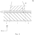
- a vehicle roof 10a shown in Fig. 4 is a first modified example of the vehicle roof 10 shown in Fig. 3 .
- Fig. 4 is a schematic partially-cut cross-sectional view of the first modified example of the vehicle roof shown in Fig. 3 .
- the vehicle roof 10a has a structure identical to that of the vehicle roof 10 except that the hinge 20 is not coated with any resin layer.
- the vehicle roof 10a includes the hinge 20.
- the hinge 20 is not coated with any resin layer.
- the thickness t 23 of the hinge resin layer 23 shown in Fig. 3 is 0 (zero).
- the vehicle roof 10 and the vehicle roof 10a have structures identical to each other.
- the hinge 20-side surfaces of the steel plate 1a of the attachment part 1 and the central part 2 of the vehicle roof 10 are coated with the first resin layer 1b. Therefore, it is possible to ensure a satisfactory rust prevention property of the attachment part 1 and the central part 2 of the vehicle roof 10. Further, since the hinge 20 is not coated with any resin layer, the total amount of the resin used for the resin layer can be reduced, thus making it possible to reduce the cost.
- a vehicle roof 10b shown in Fig. 5 is a second modified example of the vehicle roof 10 shown in Fig. 3 .
- Fig. 5 is a schematic partially-cut cross-sectional view of the second modified example of the vehicle roof shown in Fig. 3 .
- the vehicle roof 10b has a structure identical to that of the vehicle roof 10 except that the vehicle roof 10b includes a second resin layer 1c.
- the vehicle roof 10b includes the second resin layer 1c.
- the second resin layer 1c covers the central part 2.
- the vehicle roof 10b may be formed by using a tailored blank material(s).
- the tailored blank material is a steel material for press obtained by welding or joining a plurality of steel plates for a tailored blank which are made of different materials and/or have different thicknesses.
- the tailored blank material is, for example, formed by joining a steel plate, which constitutes the attachment part 1, with another steel plate, which constitutes the central part 2.
- the type of the material of each of the above-described plurality of steel plates for a tailored blank and the thickness thereof are determined according to the part of the press-molded body. Further, each of the plurality of steel plates for a tailored blank may include a resin layer.
- the types and the thicknesses of the resin layers and the steel plates may be different from one to another.
- the type of the material, the thickness, and the like of the attachment part 1 may differ from those of the central part 2.
- the type of the material, the thickness, and the like of the first resin layer 1b may differ from those of the second resin layer 1c.
- the steel plate 2a according to this embodiment has the same thickness as that of the steel plate 1a, and the second resin layer 1c is thinner than the first resin layer 1b. Note that the thickness of the steel plate 2a may differ from that of the steel plate 1a.
- the resin-coated steel plate of the vehicle roof 10b may be manufactured by, for example, welding steel plates for a tailored blank corresponding to the steel plate 2a and the steel plate 1a, respectively, to each other and thereby forming a steel material for press, and then press-molding this steel material for press.
- the vehicle-exterior-side surface of the steel plates for a tailored blank i.e., the surface of the steel plates for a tailored blank which will be disposed on the exterior side of the vehicle when the vehicle roof is mounted to the vehicle
- the vehicle-exterior-side surface of the steel plates for a tailored blank corresponding to the steel plate 1a is coated with the first resin layer 1b.
- the first resin layer 1b is thicker than the second resin layer 1c.
- the thickness t 1b of the first resin layer 1b is larger than the thickness t 1c of the second resin layer 1c.
- the second resin layer 1c has a structure similar to that of the first resin layer 1b.
- the second resin layer 1c contains a resin and has a corrosion resistance higher than that of the steel plate 1a. Owing to these features, the second resin layer 1c improves the rust prevention property of the steel plate 1a.
- the second resin layer 1c covers the central part 2 of the vehicle roof 10b. Therefore, it is possible to ensure a satisfactory rust prevention property of the central part 2. Therefore, it is possible to ensure a satisfactory rust prevention property of the central part 2 of the vehicle roof 10b as well as the satisfactory rust prevention property of the attachment part 1 thereof.
- the first resin layer 1b is thicker than the second resin layer 1c. Therefore, the total amount of the resin used for the resin layer can be reduced, thus making it possible to reduce the cost.
- the attachment part 1 and the central part 2 are formed by using a tailored blank material(s). Therefore, it is possible, by using a steel plate(s) for a tailored blank of which the thickness of a resin layer(s) is constant and the presence/absence of the resin layer is unchanged irrespective of the part of the steel plate, to easily manufacture a vehicle roof 10b of which the thickness of the resin layer varies according to the part of the steel plate. That is, it is possible to easily manufacture a vehicle roof 10b of which the thickness of the resin layer varies according to the part of the steel plate without changing the thickness of the resin layer of the same steel material for press, and without changing the presence/absence of the resin layer thereof.
- a vehicle roof 10c shown in Fig. 6 is a third modified example of the vehicle roof 10 shown in Fig. 3 .
- Fig. 6 is a schematic partially-cut cross-sectional view of the third modified example of the vehicle roof shown in Fig. 3 .
- the vehicle roof 10c has a structure identical to that of the vehicle roof 10b shown in Fig. 5 except that the vehicle roof 10c does not include the second resin layer 1c.
- the vehicle roof 10c does not include the second resin layer 1c.
- the central part 2 is not coated with any resin layer.
- the vehicle roof 10b shown in Fig. 5 has a structure identical to that of the vehicle roof 10c.
- the central part 2 is not coated with any resin layer. Accordingly, the total amount of the resin used for the resin layer can be reduced, thus making it possible to reduce the cost.
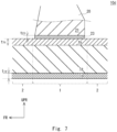
- a vehicle roof 10d shown in Fig. 7 is a fourth modified example of the vehicle roof 10 shown in Fig. 3 .
- Fig. 7 is a schematic partially-cut cross-sectional view of the fourth modified example of the vehicle roof shown in Fig. 3 .
- the vehicle roof 10d has a structure identical to that of the vehicle roof 10 shown in Fig. 3 except that the vehicle roof 10d includes a third resin layer 1d.
- the vehicle roof 10d includes the third resin layer 1d, and the third resin layer 1d covers at least a part of the vehicle-interior-side surface of the steel plate 1a (i.e., the surface of the steel plate 1a which will be disposed on the interior side of the vehicle when the vehicle roof is mounted to the vehicle).
- the third resin layer 1d is thinner than the first resin layer 1b.
- the thickness t 1d of the third resin layer 1d is thinner than the thickness t 1b of the first resin layer 1b.
- the third resin layer 1d contains a resin and has a rust prevention property higher than that of the steel plate 1a.
- the third resin layer 1d covers the vehicle-interior-side surface of the steel plate 1a, and is thinner than the first resin layer 1b. Therefore, it is possible to reduce the total amount of the resin used for the resin layer while ensuring the rust prevention property of the vehicle-interior-side surface of the steel plate 1a. Further, since the first resin layer 1b is thicker than the third resin layer 1d, the rust prevention property of the hinge 20-side surface of the steel plate 1a can be improved.
- the present disclosure is not limited to the above-described embodiments, and they may be modified as appropriate without departing from the scope and spirit of the disclosure. Further, the present disclosure may be carried out by combining the above embodiments and their examples with one another as desired.
- the hinge 20 may not be coated with any resin layer as in the case of the vehicle roof 10a shown in Fig. 4 .
- each of the vehicle roofs 10a and 10d may include the second resin layer 1c as in the case of the vehicle roof 10b.
- each of the vehicle roofs 10a and 10d may not be coated with any resin layer as in the case of the vehicle roof 10c.
- each of the vehicle roofs 10, 10a, 10b and 10c may include the third resin layer 1d as in the case of the vehicle roof 10d.
Landscapes
- Engineering & Computer Science (AREA)
- Mechanical Engineering (AREA)
- Chemical & Material Sciences (AREA)
- Combustion & Propulsion (AREA)
- Transportation (AREA)
- Architecture (AREA)
- Structural Engineering (AREA)
- Body Structure For Vehicles (AREA)
- Laminated Bodies (AREA)
Abstract
Description
- The present disclosure relates to a vehicle roof, and in particular to a vehicle roof with a hinge attached thereto.
-
Japanese Unexamined Patent Application Publication No. 2015-202686 - The inventors of the present application have conceived an idea of applying a resin-coated steel plate to a roof, a hinge, or the like of a vehicle, but have found the following problem.
- Since resin-coated steel plates are more expensive than ordinary steel plates, it is necessary to carefully select parts in a vehicle in which such expensive resin-coated steel plates are used.
- It should be noted that, in many cases, a hatchback door is attached to a roof through hinges so that the hatchback door can be opened and closed. However, a nozzle (i.e., a nozzle for spraying a sealer) cannot be easily brought close to the parts of the roof at which the hinges are attached (hereinafter also referred to as the attachment part), so that it is difficult to apply the sealer thereto. Therefore, there has been a possibility that the rust prevention property of the attachment part cannot be ensured.
- In view of the above-described problem, an object of the present disclosure is to provide a vehicle roof capable of ensuring a rust prevention property while preventing or reducing the increase in cost.
- A first exemplary aspect is a vehicle roof including an attachment part to which a hinge is attached, in which
- the attachment part includes a steel plate, and a first resin layer covering a hinge-side surface of the steel plate, and
- the first resin layer is thicker than a hinge resin layer covering the hinge.
- According to the above-described configuration, the hinge-side surface of the steel plate of the attachment part is coated with the first resin layer which is thicker than the hinge resin layer. Therefore, it is possible to ensure a satisfactory rust prevention property of the attachment part of the vehicle roof. Further, since the hinge resin layer is thinner than the first resin layer, the total amount of the resin used for the resin layer can be reduced, thus making it possible to prevent or reduce the increase in cost.
- Another exemplary aspect is a vehicle roof including an attachment part to which a hinge is attached, in which
- the attachment part includes a steel plate, and a first resin layer covering a hinge-side surface of the steel plate, and
- the hinge is not coated with any resin layer.
- According to the above-described structure, the hinge-side surface of the steel plate of the attachment part is coated with the first resin layer which is thicker than the hinge resin layer. Therefore, it is possible to ensure a satisfactory rust prevention property of the attachment part of the vehicle roof. Further, since the hinge is not coated with any resin layer, the total amount of the resin used for the resin layer can be reduced.
- Further, the vehicle roof may further include a central part that is disposed closer to a center of the vehicle roof than the attachment part is, and a second resin layer covering the central part, and the first resin layer may be thicker than the second resin layer.
- According to the above-described structure, since the first resin layer is thicker than the second resin layer covering the central part, it is possible to prevent or reduce the increase in cost while also ensuring the rust prevention property of the central part of the vehicle roof.
- Further, the vehicle roof may further include a central part that is disposed closer to a center of the vehicle roof than the attachment part is, and
the central part may not be coated with any resin layer. - According to the above-described structure, since the central part is not coated with the second resin layer, the total amount of the resin used for the resin layer can be reduced.
- Further, the vehicle roof may further include a third resin layer covering a vehicle-interior-side surface of the steel plate, and
the first resin layer may be thicker than the third resin layer. - According to the above-described structure, the third resin layer covers the vehicle-interior-side surface of the steel plate, and is thinner than the first resin layer. Therefore, it is possible to reduce the total amount of the resin used for the resin layer while ensuring the rust prevention property of the vehicle-interior-side surface of the steel plate. Further, since the first resin layer is thicker than the third resin layer, the rust prevention property of the hinge-side surface of the steel plate can be improved.
- Further, the vehicle-interior-side surface of the steel plate may not be coated with any resin layer.
- According to the above-described structure, since the vehicle-interior-side surface of the steel plate is not coated with any resin layer, the total amount of the resin used for the resin layer can be reduced.
- Further, the attachment part and the central part may be formed by using a tailored blank material.
- According to the above-described structure, the attachment part and the central part, of which the thicknesses of the resin layers differ from each other, or whether they include the resin layer or not differ from each other, can be manufactured by using a tailored blank material.
- According to the present disclosure, it is possible to ensure a rust prevention property while preventing or reducing the increase in cost.
- The above and other objects, features and advantages of the present disclosure will become more fully understood from the detailed description given hereinbelow and the accompanying drawings which are given by way of illustration only, and thus are not to be considered as limiting the present disclosure.
-
-
Fig. 1 is a perspective view showing a rear part of a vehicle including an example of a vehicle roof according to a first embodiment; -
Fig. 2 is a cross-sectional view showing a rear part of a vehicle including an example of a vehicle roof according to the first embodiment; -
Fig. 3 is a schematic partially-cut cross-sectional view of the example of the vehicle roof according to the first embodiment; -
Fig. 4 is a schematic partially-cut cross-sectional view of a first modified example of the vehicle roof according to the first embodiment; -
Fig. 5 is a schematic partially-cut cross-sectional view of a second modified example of the vehicle roof according to the first embodiment; -
Fig. 6 is a schematic partially-cut cross-sectional view of a third modified example of the vehicle roof according to the first embodiment; and -
Fig. 7 is a schematic partially-cut cross-sectional view of a fourth modified example of the vehicle roof according to the first embodiment. - Specific embodiments to which the present disclosure is applied will be described hereinafter in detail with reference to the drawings. However, the present disclosure is not limited to the below-shown embodiments. Further, the following description and drawings are simplified as appropriate for clarifying the explanation.
- A first embodiment will be described with reference to
Figs. 1 to 3 .Fig. 1 is a perspective view showing a rear part of a vehicle including an example of a vehicle roof according to the first embodiment.Fig. 2 is a cross-sectional view showing the rear part of the vehicle including the example of the vehicle roof shown inFig. 1 .Fig. 3 is a schematic partially-cut cross-sectional view of the example of the vehicle roof shown inFig. 1 . - Note that, needless to say, three-dimensional coordinate systems shown in
Fig. 1 and the other drawings are shown just for explaining the positional relationship among components. In general, in the drawings, a symbol "UPR" indicates the upward of the vehicle; "FR" indicates the forward of the vehicle; and "LH" indicates the left side of the vehicle. These symbols are common throughout the drawings. The side opposite to the UPR indicates the interior side of vehicle. - As shown in
Fig. 1 , avehicle roof 10 includes anattachment part 1 to which ahinge 20 is attached. Thevehicle roof 10 may be formed by pressing and/or cutting a resin-coated steel plate as appropriate. Theattachment part 1 is also referred to as a roof hinge part. Thehinge 20 is attached to thevehicle roof 10 and to aback door 30. Specifically, thehinge 20 includes attachingparts part 21 is attached to theattachment part 1 of thevehicle roof 10. It is difficult to apply a sealer or a wax, which is applied in order to prevent rusting, to the front side of the contact interface between theattachment part 1 and the attachingpart 21. A back door inner 30b (which will be described later) of theback door 30 is attached to the attachingpart 22. - As shown in
Fig. 2 , theback door 30 is attached to thevehicle roof 10 through thehinge 20 in such a manner that theback door 30 can be rotated around a backdoor rotation axis 20a of thehinge 20. Theback door 30 includes a back door outer 30a, the back door inner 30b, and aback door glass 30c. Theback door 30 is rotated around the backdoor rotation axis 20a, so that it is opened in such a manner that theback door glass 30c is moved upward. - As shown in
Fig. 3 , thevehicle roof 10 includes asteel plate 1a and afirst resin layer 1b. Thevehicle roof 10 has similar structures in theattachment part 1 and in thecentral part 2. Thecentral part 2 is a part that is located closer to the center of the vehicle roof than theattachment part 1 of thevehicle roof 10 is. Thecentral part 2 is preferably continuous with theattachment part 1. - The
steel plate 1a has a shape that conforms to the shape of the roof of the vehicle. Thesteel plate 1a has mechanical properties required as the material of thevehicle roof 10. Specifically, thesteel plate 1a is preferably made of a normal steel or a steel containing an additive element(s) such as chromium. Further, a plating film may be provided on the surface of thesteel plate 1a. The type of the plating film provided on the surface of thesteel plate 1a is not limited any particular types. Examples of applicable plating films include plating containing at least one of zinc, aluminum, cobalt, tin, and nickel, and alloy plating containing at least one of these metallic elements, other metallic elements, and/or non-metallic elements. Further, depending on the use, both surfaces of the metal plate or only one surface thereof may be coated with a coating film. Further, either only a part(s) of the surface of the metal plate or the entire surface thereof may be coated with a coating film. - The
first resin layer 1b covers the surface of thesteel plate 1a on the side on which thehinge 20 is located (which is also referred to as the hinge 20-side surface of thesteel plate 1a). Thefirst resin layer 1b contains a resin and has a rust prevention property higher than that of thesteel plate 1a. As a result, thefirst resin layer 1b improves the rust prevention property of thesteel plate 1a. Examples of such a resin include a water-based coating composition or an organic resin such as an organic solvent-based coating composition. In order to further improve the adhesion of thefirst resin layer 1b to thesteel plate 1a, the corrosion resistance of thesteel plate 1a, and the like, an undercoating film may be provided between thefirst resin layer 1b and the surface of thesteel plate 1a. In the case where such an undercoating film is provided as described above, the number of undercoating layers and the composition thereof are not limited to any particular numbers and any particular compositions. Thefirst resin layer 1b may further contain a pigment(s). Examples of such pigments include rust prevention pigments and conductive pigments. The type of the rust prevention pigment and the type of the conductive pigment are not limited to any particular types of pigments. However, the rust prevention pigment preferably includes, for example, at least one substance selected from silicate compounds, phosphate compounds, vanadate compounds, and metal oxide fine particles. Further, the conductive pigment preferably contains, for example, at least one substance selected from metals, alloys, conductive carbon, iron phosphide, carbides, and semiconductor oxides. - Note that the
vehicle roof 10 may include at least one of an electrodeposition coating layer, an intermediate coating layer, and a top coating layer. At least one of the electrodeposition coating layer, the intermediate coating layer, and the top coating layer covers at least a part of thefirst resin layer 1b. - The
hinge 20 is in contact with theattachment part 1. Thehinge 20 is in contact with thesteel plate 1a through thefirst resin layer 1b. (i.e., thefirst resin layer 1b is provided between thehinge 20 and thesteel plate 1a. Thefirst resin layer 1b insulates thesteel plate 1a against thehinge 20.) Thefirst resin layer 1b has a predetermined thickness t1b. - The
hinge 20 includes the attachingparts hinge resin layer 23. Thehinge resin layer 23 covers the surface of the attachingpart 21 of thevehicle roof 10 on the side on which theattachment part 1 is located. Thefirst resin layer 1b is thicker than thehinge resin layer 23. In other words, the thickness t1b of thefirst resin layer 1b is larger than the thickness t23 of thehinge resin layer 23. - According to the above-described structure of the
vehicle roof 10, the surface of thesteel plate 1a of theattachment part 1 on the side on which thehinge 20 is located (which is also referred to as the hinge 20-side surface of thesteel plate 1a of the attachment part 1) is coated with thefirst resin layer 1b which is thicker than thehinge resin layer 23. Therefore, it is possible to ensure a satisfactory rust prevention property of theattachment part 1 of thevehicle roof 10. Further, since thehinge resin layer 23 is thinner than thefirst resin layer 1b, the total amount of the resin can be reduced, thus making it possible to prevent or reduce the increase in cost. - Further, according to the structure of the
vehicle roof 10, the surface of thesteel plate 1a of thecentral part 2 on the side on which thehinge 20 is located (which is also referred to as the hinge 20-side surface of thesteel plate 1a of the central part 2) is also coated with thefirst resin layer 1b. Therefore, it is also possible to ensure a satisfactory rust prevention property of thecentral part 2 of thevehicle roof 10. Further, it is also possible to ensure a satisfactory rust prevention property of a part(s) where a sealer or a wax cannot be easily applied, and a satisfactory rust prevention property of the front side of the contact interface between theattachment part 1 and the attachingpart 21. - Next, an example of a method for manufacturing a
vehicle roof 10 will be described. Firstly, a coating film is applied to (i.e., is formed on) the hinge 20-side surface of thesteel plate 1a, and afirst resin layer 1b is thereby formed on the hinge 20-side surface of thesteel plate 1a. Next, thesteel plate 1a, on which thefirst resin layer 1b has been formed, is processed or molded into a shape that conforms to the shape of the roof of the vehicle. In this way, thevehicle roof 10 can be manufactured. If necessary, at least one of electrodeposition coating, intermediate coating, and top coating may be applied to (i.e., formed on) the above-described processed or moldedsteel plate 1a. - A
vehicle roof 10a shown inFig. 4 is a first modified example of thevehicle roof 10 shown inFig. 3 .Fig. 4 is a schematic partially-cut cross-sectional view of the first modified example of the vehicle roof shown inFig. 3 . Thevehicle roof 10a has a structure identical to that of thevehicle roof 10 except that thehinge 20 is not coated with any resin layer. - The
vehicle roof 10a includes thehinge 20. Thehinge 20 is not coated with any resin layer. In other words, the thickness t23 of thehinge resin layer 23 shown inFig. 3 is 0 (zero). When the thickness t23 of thehinge resin layer 23 of thevehicle roof 10 shown inFig. 3 is zero, thevehicle roof 10 and thevehicle roof 10a have structures identical to each other. - According to the above-described structure of the
vehicle roof 10a, similarly to thevehicle roof 10, the hinge 20-side surfaces of thesteel plate 1a of theattachment part 1 and thecentral part 2 of thevehicle roof 10 are coated with thefirst resin layer 1b. Therefore, it is possible to ensure a satisfactory rust prevention property of theattachment part 1 and thecentral part 2 of thevehicle roof 10. Further, since thehinge 20 is not coated with any resin layer, the total amount of the resin used for the resin layer can be reduced, thus making it possible to reduce the cost. - A
vehicle roof 10b shown inFig. 5 is a second modified example of thevehicle roof 10 shown inFig. 3 .Fig. 5 is a schematic partially-cut cross-sectional view of the second modified example of the vehicle roof shown inFig. 3 . Thevehicle roof 10b has a structure identical to that of thevehicle roof 10 except that thevehicle roof 10b includes asecond resin layer 1c. - As shown in
Fig. 5 , thevehicle roof 10b includes thesecond resin layer 1c. Thesecond resin layer 1c covers thecentral part 2. Thevehicle roof 10b may be formed by using a tailored blank material(s). The tailored blank material is a steel material for press obtained by welding or joining a plurality of steel plates for a tailored blank which are made of different materials and/or have different thicknesses. The tailored blank material is, for example, formed by joining a steel plate, which constitutes theattachment part 1, with another steel plate, which constitutes thecentral part 2. The type of the material of each of the above-described plurality of steel plates for a tailored blank and the thickness thereof are determined according to the part of the press-molded body. Further, each of the plurality of steel plates for a tailored blank may include a resin layer. Further, the types and the thicknesses of the resin layers and the steel plates may be different from one to another. The type of the material, the thickness, and the like of theattachment part 1 may differ from those of thecentral part 2. The type of the material, the thickness, and the like of thefirst resin layer 1b may differ from those of thesecond resin layer 1c. Thesteel plate 2a according to this embodiment has the same thickness as that of thesteel plate 1a, and thesecond resin layer 1c is thinner than thefirst resin layer 1b. Note that the thickness of thesteel plate 2a may differ from that of thesteel plate 1a. The resin-coated steel plate of thevehicle roof 10b may be manufactured by, for example, welding steel plates for a tailored blank corresponding to thesteel plate 2a and thesteel plate 1a, respectively, to each other and thereby forming a steel material for press, and then press-molding this steel material for press. The vehicle-exterior-side surface of the steel plates for a tailored blank (i.e., the surface of the steel plates for a tailored blank which will be disposed on the exterior side of the vehicle when the vehicle roof is mounted to the vehicle) corresponding to thesteel plate 2a is coated with thesecond resin layer 1c. The vehicle-exterior-side surface of the steel plates for a tailored blank corresponding to thesteel plate 1a is coated with thefirst resin layer 1b. - The
first resin layer 1b is thicker than thesecond resin layer 1c. In other words, the thickness t1b of thefirst resin layer 1b is larger than the thickness t1c of thesecond resin layer 1c. Thesecond resin layer 1c has a structure similar to that of thefirst resin layer 1b. Thesecond resin layer 1c contains a resin and has a corrosion resistance higher than that of thesteel plate 1a. Owing to these features, thesecond resin layer 1c improves the rust prevention property of thesteel plate 1a. - According to the above-described structure of the
vehicle roof 10b, thesecond resin layer 1c covers thecentral part 2 of thevehicle roof 10b. Therefore, it is possible to ensure a satisfactory rust prevention property of thecentral part 2. Therefore, it is possible to ensure a satisfactory rust prevention property of thecentral part 2 of thevehicle roof 10b as well as the satisfactory rust prevention property of theattachment part 1 thereof. - Further, according to the structure of the
vehicle roof 10b, thefirst resin layer 1b is thicker than thesecond resin layer 1c. Therefore, the total amount of the resin used for the resin layer can be reduced, thus making it possible to reduce the cost. - Further, according to the structure of the
vehicle roof 10b, theattachment part 1 and thecentral part 2 are formed by using a tailored blank material(s). Therefore, it is possible, by using a steel plate(s) for a tailored blank of which the thickness of a resin layer(s) is constant and the presence/absence of the resin layer is unchanged irrespective of the part of the steel plate, to easily manufacture avehicle roof 10b of which the thickness of the resin layer varies according to the part of the steel plate. That is, it is possible to easily manufacture avehicle roof 10b of which the thickness of the resin layer varies according to the part of the steel plate without changing the thickness of the resin layer of the same steel material for press, and without changing the presence/absence of the resin layer thereof. - A
vehicle roof 10c shown inFig. 6 is a third modified example of thevehicle roof 10 shown inFig. 3 .Fig. 6 is a schematic partially-cut cross-sectional view of the third modified example of the vehicle roof shown inFig. 3 . Thevehicle roof 10c has a structure identical to that of thevehicle roof 10b shown inFig. 5 except that thevehicle roof 10c does not include thesecond resin layer 1c. - The
vehicle roof 10c does not include thesecond resin layer 1c. Thecentral part 2 is not coated with any resin layer. In other words, when the thickness t1c of thesecond resin layer 1c is 0 (zero), thevehicle roof 10b shown inFig. 5 has a structure identical to that of thevehicle roof 10c. - Therefore, according to the structure of the
vehicle roof 10c, thecentral part 2 is not coated with any resin layer. Accordingly, the total amount of the resin used for the resin layer can be reduced, thus making it possible to reduce the cost. - A
vehicle roof 10d shown inFig. 7 is a fourth modified example of thevehicle roof 10 shown inFig. 3 .Fig. 7 is a schematic partially-cut cross-sectional view of the fourth modified example of the vehicle roof shown inFig. 3 . Thevehicle roof 10d has a structure identical to that of thevehicle roof 10 shown inFig. 3 except that thevehicle roof 10d includes athird resin layer 1d. - The
vehicle roof 10d includes thethird resin layer 1d, and thethird resin layer 1d covers at least a part of the vehicle-interior-side surface of thesteel plate 1a (i.e., the surface of thesteel plate 1a which will be disposed on the interior side of the vehicle when the vehicle roof is mounted to the vehicle). Thethird resin layer 1d is thinner than thefirst resin layer 1b. The thickness t1d of thethird resin layer 1d is thinner than the thickness t1b of thefirst resin layer 1b. Similarly to thefirst resin layer 1b, thethird resin layer 1d contains a resin and has a rust prevention property higher than that of thesteel plate 1a. - Therefore, according to the structure of the
vehicle roof 10d, thethird resin layer 1d covers the vehicle-interior-side surface of thesteel plate 1a, and is thinner than thefirst resin layer 1b. Therefore, it is possible to reduce the total amount of the resin used for the resin layer while ensuring the rust prevention property of the vehicle-interior-side surface of thesteel plate 1a. Further, since thefirst resin layer 1b is thicker than thethird resin layer 1d, the rust prevention property of the hinge 20-side surface of thesteel plate 1a can be improved. - Note that the present disclosure is not limited to the above-described embodiments, and they may be modified as appropriate without departing from the scope and spirit of the disclosure. Further, the present disclosure may be carried out by combining the above embodiments and their examples with one another as desired. For example, in each of the
vehicle roofs Figs. 5 ,6 and7 , respectively, thehinge 20 may not be coated with any resin layer as in the case of thevehicle roof 10a shown inFig. 4 . Further, each of thevehicle roofs second resin layer 1c as in the case of thevehicle roof 10b. Further, in each of thevehicle roofs central part 2 may not be coated with any resin layer as in the case of thevehicle roof 10c. Further, each of thevehicle roofs third resin layer 1d as in the case of thevehicle roof 10d. - From the disclosure thus described, it will be obvious that the embodiments of the disclosure may be varied in many ways. Such variations are not to be regarded as a departure from the spirit and scope of the disclosure, and all such modifications as would be obvious to one skilled in the art are intended for inclusion within the scope of the following claims.
Claims (7)
- A vehicle roof (10) comprising an attachment part (1) to which a hinge (20) is attached, wherein
the attachment part (1) comprises a steel plate (1a), and a first resin layer (1b) covering a hinge (20)-side surface of the steel plate (1a), and
the first resin layer (1) is thicker than a hinge resin layer (23) covering the hinge (20). - A vehicle roof (10a) comprising an attachment part (1) to which a hinge (20) is attached, wherein
the attachment part (1) comprises a steel plate (1a), and a first resin layer (1b) covering a hinge (20)-side surface of the steel plate (1a), and
the hinge (10) is not coated with any resin layer (23). - The vehicle roof (10b) according to Claim 1 or 2, further comprising a central part (2) that is disposed closer to a center of the vehicle roof than the attachment part (1) is, and a second resin layer (1c) covering the central part (2), wherein
the first resin layer (1b) is thicker than the second resin layer (1c). - The vehicle roof (10c) according to Claim 1 or 2, further comprising a central part (2) that is disposed closer to a center of the vehicle roof than the attachment part (1) is, wherein
the central part (2) is not coated with any resin layer (1c). - The vehicle roof (10d) according to any one of Claims 1 to 4, further comprising a third resin layer (1d) covering a vehicle-interior-side surface of the steel plate (1a), wherein
the first resin layer (1b) is thicker than the third resin layer (1d). - The vehicle roof (10) according to any one of Claims 1 to 4, wherein the vehicle-interior-side surface of the steel plate (1a) is not coated with any resin layer (1d).
- The vehicle roof (10b) according to Claim 3 or 4, Claim 5 dependent on Claim 3 or 4, or Claim 6 dependent on Claim 3 or 4, wherein the attachment part (1) and the central part (2) are formed by using a tailored blank material.
Applications Claiming Priority (1)
| Application Number | Priority Date | Filing Date | Title |
|---|---|---|---|
| JP2021205302A JP7567768B2 (en) | 2021-12-17 | 2021-12-17 | Vehicle roof |
Publications (3)
| Publication Number | Publication Date |
|---|---|
| EP4215283A1 true EP4215283A1 (en) | 2023-07-26 |
| EP4215283C0 EP4215283C0 (en) | 2025-11-12 |
| EP4215283B1 EP4215283B1 (en) | 2025-11-12 |
Family
ID=84361798
Family Applications (1)
| Application Number | Title | Priority Date | Filing Date |
|---|---|---|---|
| EP22208984.9A Active EP4215283B1 (en) | 2021-12-17 | 2022-11-23 | Vehicle roof |
Country Status (4)
| Country | Link |
|---|---|
| US (1) | US20230192194A1 (en) |
| EP (1) | EP4215283B1 (en) |
| JP (1) | JP7567768B2 (en) |
| CN (1) | CN116265326B (en) |
Citations (5)
| Publication number | Priority date | Publication date | Assignee | Title |
|---|---|---|---|---|
| US20060290169A1 (en) * | 2005-06-27 | 2006-12-28 | Mazda Motor Corporation | Vehicle rear body structure |
| JP2015202686A (en) | 2014-04-16 | 2015-11-16 | 新日鐵住金株式会社 | Coated metal plate for automobile excellent in resistance weldability, corrosion resistance and moldability |
| US10336047B2 (en) * | 2015-03-26 | 2019-07-02 | Mahindra And Mahindra Limited | Method of preventing corrosion of mating surfaces of components |
| US10378819B2 (en) * | 2015-01-26 | 2019-08-13 | Nissan Motor Co., Ltd. | Paint baking oven and paint baking method |
| WO2022215384A1 (en) * | 2021-04-05 | 2022-10-13 | 株式会社クボタ | Member being fastened, coating jig therefor, and coating method therefor |
Family Cites Families (17)
| Publication number | Priority date | Publication date | Assignee | Title |
|---|---|---|---|---|
| JPS5822817Y2 (en) * | 1976-11-29 | 1983-05-16 | マツダ株式会社 | Waterproof structure of hinge part of automobile opening/closing lid |
| JPS5599364A (en) * | 1979-01-23 | 1980-07-29 | Takara Kenzai Seisakusho:Goushi | Installation method of vehicle roof |
| JPH0688493B2 (en) * | 1987-09-09 | 1994-11-09 | 株式会社大井製作所 | Car door mounting structure |
| JPH09226469A (en) * | 1996-02-22 | 1997-09-02 | Hashimoto Forming Ind Co Ltd | Roof rack for vehicle and manufacture thereof |
| DE19612898C1 (en) * | 1996-03-30 | 1997-04-03 | Herberts Gmbh | Coating coils of sheet material |
| KR19980035853U (en) * | 1996-12-13 | 1998-09-15 | 김영귀 | Hatch-back vehicle's rear header panel structure |
| JP2000038158A (en) * | 1998-07-24 | 2000-02-08 | Suzuki Motor Corp | Car roof structure |
| JP4147633B2 (en) | 1998-08-28 | 2008-09-10 | 富士重工業株式会社 | Back door opening / closing mechanism and assembly method |
| JP2007001521A (en) * | 2005-06-27 | 2007-01-11 | Mazda Motor Corp | Car body rear structure |
| JP4506632B2 (en) | 2005-09-30 | 2010-07-21 | 株式会社Ihi | Butt welding method and apparatus |
| CN103228472B (en) * | 2010-11-29 | 2016-04-20 | 本田技研工业株式会社 | Open/close device for vehicle |
| WO2013021452A1 (en) * | 2011-08-08 | 2013-02-14 | トヨタ自動車株式会社 | Resin roof structure |
| CN203497013U (en) | 2013-10-10 | 2014-03-26 | 东风汽车公司 | Rear roof cross beam of two-compartment passenger vehicle bodywork |
| DE102015119454A1 (en) * | 2015-11-11 | 2017-05-11 | Webasto SE | Flat vehicle body part |
| JP6595521B2 (en) * | 2017-02-08 | 2019-10-23 | トヨタ自動車株式会社 | Body superstructure |
| CN110065241A (en) * | 2019-03-22 | 2019-07-30 | 武汉格罗夫氢能汽车有限公司 | A kind of SUV automobile top cover of continuous carbon fibre composite material and preparation method thereof |
| US11028626B2 (en) * | 2019-07-08 | 2021-06-08 | Ford Global Technologies, Llc | Roof hinge cover attachment strategies |
-
2021
- 2021-12-17 JP JP2021205302A patent/JP7567768B2/en active Active
-
2022
- 2022-11-21 US US17/991,072 patent/US20230192194A1/en not_active Abandoned
- 2022-11-23 EP EP22208984.9A patent/EP4215283B1/en active Active
- 2022-12-15 CN CN202211617956.7A patent/CN116265326B/en active Active
Patent Citations (5)
| Publication number | Priority date | Publication date | Assignee | Title |
|---|---|---|---|---|
| US20060290169A1 (en) * | 2005-06-27 | 2006-12-28 | Mazda Motor Corporation | Vehicle rear body structure |
| JP2015202686A (en) | 2014-04-16 | 2015-11-16 | 新日鐵住金株式会社 | Coated metal plate for automobile excellent in resistance weldability, corrosion resistance and moldability |
| US10378819B2 (en) * | 2015-01-26 | 2019-08-13 | Nissan Motor Co., Ltd. | Paint baking oven and paint baking method |
| US10336047B2 (en) * | 2015-03-26 | 2019-07-02 | Mahindra And Mahindra Limited | Method of preventing corrosion of mating surfaces of components |
| WO2022215384A1 (en) * | 2021-04-05 | 2022-10-13 | 株式会社クボタ | Member being fastened, coating jig therefor, and coating method therefor |
Also Published As
| Publication number | Publication date |
|---|---|
| EP4215283C0 (en) | 2025-11-12 |
| JP7567768B2 (en) | 2024-10-16 |
| EP4215283B1 (en) | 2025-11-12 |
| JP2023090371A (en) | 2023-06-29 |
| CN116265326A (en) | 2023-06-20 |
| CN116265326B (en) | 2025-02-07 |
| US20230192194A1 (en) | 2023-06-22 |
Similar Documents
| Publication | Publication Date | Title |
|---|---|---|
| US8956469B2 (en) | Vehicle body components with a metal hybrid construction and production methods for such vehicle body components | |
| EP1051539B1 (en) | Surface-treated steel sheet for fuel tanks and method of fabricating same | |
| US6797372B2 (en) | Resin-coated steel for fuel tanks of automobile and method for manufacturing the same | |
| US4705726A (en) | Anticorrosive weldable coated steel | |
| EP4215283B1 (en) | Vehicle roof | |
| MIURA et al. | Development of new corrosion-resistant steel sheets for automobiles | |
| JP7697361B2 (en) | Vehicle outer panel and vehicle hood | |
| KR101375510B1 (en) | Rust-proof steel sheet and method for producing the same | |
| US20230242186A1 (en) | Vehicle floor structure and method for manufacturing vehicle | |
| JP7658261B2 (en) | Vehicle roof | |
| JP2008188594A (en) | Inverter cover | |
| JPH062161A (en) | Galvanized steel sheet excellent in formability, external appearance characteristic after forming, and corrosion resistance | |
| JP2794351B2 (en) | Method of forming automobile body using pre-coated metal plate | |
| JP7609051B2 (en) | Vehicle roof | |
| JPH01201488A (en) | Rust inhibitive lubricated steel sheet having excellent weldability and electrodeposition paintability | |
| US20040238371A1 (en) | Coated method for light metal alloys | |
| JP2005288732A (en) | Non-welded organic coated steel sheet for automobiles with excellent corrosion resistance | |
| JPH042780A (en) | High corrosion-resistant colored surface treated steel sheet | |
| US12312012B2 (en) | Vehicle floor structure and method for manufacturing vehicle | |
| JP2003267336A (en) | Press-molded can using precoated steel plate | |
| JP2000070842A (en) | Resin-coated steel sheet for automotive repair parts | |
| JPS6248539A (en) | High corrosion-resistant weldable coated steel plate | |
| KR100765056B1 (en) | Dissimilar Resin Coated Steel Sheet for Automobile Exterior | |
| JPH0120058B2 (en) | ||
| JP2000178757A (en) | Lubricated steel sheet with excellent conductivity and workability |
Legal Events
| Date | Code | Title | Description |
|---|---|---|---|
| PUAI | Public reference made under article 153(3) epc to a published international application that has entered the european phase |
Free format text: ORIGINAL CODE: 0009012 |
|
| STAA | Information on the status of an ep patent application or granted ep patent |
Free format text: STATUS: REQUEST FOR EXAMINATION WAS MADE |
|
| 17P | Request for examination filed |
Effective date: 20221123 |
|
| AK | Designated contracting states |
Kind code of ref document: A1 Designated state(s): AL AT BE BG CH CY CZ DE DK EE ES FI FR GB GR HR HU IE IS IT LI LT LU LV MC ME MK MT NL NO PL PT RO RS SE SI SK SM TR |
|
| GRAP | Despatch of communication of intention to grant a patent |
Free format text: ORIGINAL CODE: EPIDOSNIGR1 |
|
| STAA | Information on the status of an ep patent application or granted ep patent |
Free format text: STATUS: GRANT OF PATENT IS INTENDED |
|
| RIC1 | Information provided on ipc code assigned before grant |
Ipc: B05D 7/14 20060101AFI20250626BHEP Ipc: B60J 5/10 20060101ALI20250626BHEP Ipc: E05D 5/02 20060101ALI20250626BHEP |
|
| INTG | Intention to grant announced |
Effective date: 20250711 |
|
| GRAS | Grant fee paid |
Free format text: ORIGINAL CODE: EPIDOSNIGR3 |
|
| RIN1 | Information on inventor provided before grant (corrected) |
Inventor name: TANAKA, YUYA Inventor name: MATSUOKA, TOMOAKI Inventor name: TSUZUKI, YOSHIHIKO Inventor name: KONDO, NOBUYO |
|
| GRAA | (expected) grant |
Free format text: ORIGINAL CODE: 0009210 |
|
| STAA | Information on the status of an ep patent application or granted ep patent |
Free format text: STATUS: THE PATENT HAS BEEN GRANTED |
|
| AK | Designated contracting states |
Kind code of ref document: B1 Designated state(s): AL AT BE BG CH CY CZ DE DK EE ES FI FR GB GR HR HU IE IS IT LI LT LU LV MC ME MK MT NL NO PL PT RO RS SE SI SK SM TR |
|
| REG | Reference to a national code |
Ref country code: CH Ref legal event code: F10 Free format text: ST27 STATUS EVENT CODE: U-0-0-F10-F00 (AS PROVIDED BY THE NATIONAL OFFICE) Effective date: 20251112 Ref country code: GB Ref legal event code: FG4D |
|
| REG | Reference to a national code |
Ref country code: IE Ref legal event code: FG4D |
|
| REG | Reference to a national code |
Ref country code: DE Ref legal event code: R096 Ref document number: 602022024821 Country of ref document: DE |
|
| PGFP | Annual fee paid to national office [announced via postgrant information from national office to epo] |
Ref country code: AT Payment date: 20260113 Year of fee payment: 4 |
|
| U01 | Request for unitary effect filed |
Effective date: 20251212 |
|
| U07 | Unitary effect registered |
Designated state(s): AT BE BG DE DK EE FI FR IT LT LU LV MT NL PT RO SE SI Effective date: 20251218 |
|
| U20 | Renewal fee for the european patent with unitary effect paid |
Year of fee payment: 4 Effective date: 20260106 |
|
| PG25 | Lapsed in a contracting state [announced via postgrant information from national office to epo] |
Ref country code: ES Free format text: LAPSE BECAUSE OF FAILURE TO SUBMIT A TRANSLATION OF THE DESCRIPTION OR TO PAY THE FEE WITHIN THE PRESCRIBED TIME-LIMIT Effective date: 20251112 |
|
| PG25 | Lapsed in a contracting state [announced via postgrant information from national office to epo] |
Ref country code: NO Free format text: LAPSE BECAUSE OF FAILURE TO SUBMIT A TRANSLATION OF THE DESCRIPTION OR TO PAY THE FEE WITHIN THE PRESCRIBED TIME-LIMIT Effective date: 20260212 |
|
| PG25 | Lapsed in a contracting state [announced via postgrant information from national office to epo] |
Ref country code: HR Free format text: LAPSE BECAUSE OF FAILURE TO SUBMIT A TRANSLATION OF THE DESCRIPTION OR TO PAY THE FEE WITHIN THE PRESCRIBED TIME-LIMIT Effective date: 20251112 |
|
| PG25 | Lapsed in a contracting state [announced via postgrant information from national office to epo] |
Ref country code: RS Free format text: LAPSE BECAUSE OF FAILURE TO SUBMIT A TRANSLATION OF THE DESCRIPTION OR TO PAY THE FEE WITHIN THE PRESCRIBED TIME-LIMIT Effective date: 20260212 |
|
| PG25 | Lapsed in a contracting state [announced via postgrant information from national office to epo] |
Ref country code: IS Free format text: LAPSE BECAUSE OF FAILURE TO SUBMIT A TRANSLATION OF THE DESCRIPTION OR TO PAY THE FEE WITHIN THE PRESCRIBED TIME-LIMIT Effective date: 20260312 |
|
| PG25 | Lapsed in a contracting state [announced via postgrant information from national office to epo] |
Ref country code: PL Free format text: LAPSE BECAUSE OF FAILURE TO SUBMIT A TRANSLATION OF THE DESCRIPTION OR TO PAY THE FEE WITHIN THE PRESCRIBED TIME-LIMIT Effective date: 20251112 |
|
| U1N | Appointed representative for the unitary patent procedure changed after the registration of the unitary effect |
Representative=s name: MARKS & CLERK LLP; GB |