EP4215133A1 - Heat sinks for catheters and systems thereof - Google Patents
Heat sinks for catheters and systems thereof Download PDFInfo
- Publication number
- EP4215133A1 EP4215133A1 EP23161174.0A EP23161174A EP4215133A1 EP 4215133 A1 EP4215133 A1 EP 4215133A1 EP 23161174 A EP23161174 A EP 23161174A EP 4215133 A1 EP4215133 A1 EP 4215133A1
- Authority
- EP
- European Patent Office
- Prior art keywords
- core wire
- ultrasound
- sleeve
- damping
- catheter assembly
- Prior art date
- Legal status (The legal status is an assumption and is not a legal conclusion. Google has not performed a legal analysis and makes no representation as to the accuracy of the status listed.)
- Granted
Links
Images


Classifications
-
- A—HUMAN NECESSITIES
- A61—MEDICAL OR VETERINARY SCIENCE; HYGIENE
- A61B—DIAGNOSIS; SURGERY; IDENTIFICATION
- A61B17/00—Surgical instruments, devices or methods
- A61B17/22—Implements for squeezing-off ulcers or the like on inner organs of the body; Implements for scraping-out cavities of body organs, e.g. bones; for invasive removal or destruction of calculus using mechanical vibrations; for removing obstructions in blood vessels, not otherwise provided for
- A61B17/22004—Implements for squeezing-off ulcers or the like on inner organs of the body; Implements for scraping-out cavities of body organs, e.g. bones; for invasive removal or destruction of calculus using mechanical vibrations; for removing obstructions in blood vessels, not otherwise provided for using mechanical vibrations, e.g. ultrasonic shock waves
- A61B17/22012—Implements for squeezing-off ulcers or the like on inner organs of the body; Implements for scraping-out cavities of body organs, e.g. bones; for invasive removal or destruction of calculus using mechanical vibrations; for removing obstructions in blood vessels, not otherwise provided for using mechanical vibrations, e.g. ultrasonic shock waves in direct contact with, or very close to, the obstruction or concrement
-
- A—HUMAN NECESSITIES
- A61—MEDICAL OR VETERINARY SCIENCE; HYGIENE
- A61B—DIAGNOSIS; SURGERY; IDENTIFICATION
- A61B17/00—Surgical instruments, devices or methods
- A61B2017/00477—Coupling
-
- A—HUMAN NECESSITIES
- A61—MEDICAL OR VETERINARY SCIENCE; HYGIENE
- A61B—DIAGNOSIS; SURGERY; IDENTIFICATION
- A61B17/00—Surgical instruments, devices or methods
- A61B17/22—Implements for squeezing-off ulcers or the like on inner organs of the body; Implements for scraping-out cavities of body organs, e.g. bones; for invasive removal or destruction of calculus using mechanical vibrations; for removing obstructions in blood vessels, not otherwise provided for
- A61B17/22004—Implements for squeezing-off ulcers or the like on inner organs of the body; Implements for scraping-out cavities of body organs, e.g. bones; for invasive removal or destruction of calculus using mechanical vibrations; for removing obstructions in blood vessels, not otherwise provided for using mechanical vibrations, e.g. ultrasonic shock waves
- A61B17/22012—Implements for squeezing-off ulcers or the like on inner organs of the body; Implements for scraping-out cavities of body organs, e.g. bones; for invasive removal or destruction of calculus using mechanical vibrations; for removing obstructions in blood vessels, not otherwise provided for using mechanical vibrations, e.g. ultrasonic shock waves in direct contact with, or very close to, the obstruction or concrement
- A61B2017/22014—Implements for squeezing-off ulcers or the like on inner organs of the body; Implements for scraping-out cavities of body organs, e.g. bones; for invasive removal or destruction of calculus using mechanical vibrations; for removing obstructions in blood vessels, not otherwise provided for using mechanical vibrations, e.g. ultrasonic shock waves in direct contact with, or very close to, the obstruction or concrement the ultrasound transducer being outside patient's body; with an ultrasound transmission member; with a wave guide; with a vibrated guide wire
-
- A—HUMAN NECESSITIES
- A61—MEDICAL OR VETERINARY SCIENCE; HYGIENE
- A61B—DIAGNOSIS; SURGERY; IDENTIFICATION
- A61B17/00—Surgical instruments, devices or methods
- A61B17/22—Implements for squeezing-off ulcers or the like on inner organs of the body; Implements for scraping-out cavities of body organs, e.g. bones; for invasive removal or destruction of calculus using mechanical vibrations; for removing obstructions in blood vessels, not otherwise provided for
- A61B17/22004—Implements for squeezing-off ulcers or the like on inner organs of the body; Implements for scraping-out cavities of body organs, e.g. bones; for invasive removal or destruction of calculus using mechanical vibrations; for removing obstructions in blood vessels, not otherwise provided for using mechanical vibrations, e.g. ultrasonic shock waves
- A61B17/22012—Implements for squeezing-off ulcers or the like on inner organs of the body; Implements for scraping-out cavities of body organs, e.g. bones; for invasive removal or destruction of calculus using mechanical vibrations; for removing obstructions in blood vessels, not otherwise provided for using mechanical vibrations, e.g. ultrasonic shock waves in direct contact with, or very close to, the obstruction or concrement
- A61B2017/22014—Implements for squeezing-off ulcers or the like on inner organs of the body; Implements for scraping-out cavities of body organs, e.g. bones; for invasive removal or destruction of calculus using mechanical vibrations; for removing obstructions in blood vessels, not otherwise provided for using mechanical vibrations, e.g. ultrasonic shock waves in direct contact with, or very close to, the obstruction or concrement the ultrasound transducer being outside patient's body; with an ultrasound transmission member; with a wave guide; with a vibrated guide wire
- A61B2017/22015—Implements for squeezing-off ulcers or the like on inner organs of the body; Implements for scraping-out cavities of body organs, e.g. bones; for invasive removal or destruction of calculus using mechanical vibrations; for removing obstructions in blood vessels, not otherwise provided for using mechanical vibrations, e.g. ultrasonic shock waves in direct contact with, or very close to, the obstruction or concrement the ultrasound transducer being outside patient's body; with an ultrasound transmission member; with a wave guide; with a vibrated guide wire with details of the transmission member
-
- A—HUMAN NECESSITIES
- A61—MEDICAL OR VETERINARY SCIENCE; HYGIENE
- A61B—DIAGNOSIS; SURGERY; IDENTIFICATION
- A61B17/00—Surgical instruments, devices or methods
- A61B17/32—Surgical cutting instruments
- A61B17/320068—Surgical cutting instruments using mechanical vibrations, e.g. ultrasonic
- A61B2017/320088—Surgical cutting instruments using mechanical vibrations, e.g. ultrasonic with acoustic insulation, e.g. elements for damping vibrations between horn and surrounding sheath
Definitions
- Atherosclerosis is characterized by one or more intravascular lesions formed, in part, of plaque including blood-borne substances such as fat, cholesterol, or calcium.
- An intravascular lesion such as an arterial lesion can form on a wall of an arterial lumen and build out across the lumen to an opposite arterial wall. A last point of patency often occurs at a boundary between the arterial lesion and the opposite arterial wall.
- Surgical procedures for atherosclerosis such as atherectomy can be used to restore patency and blood flow impeded by such lesions.
- endoluminal devices such as catheters for modification of intravascular lesions can lead to heat-related complications for the endoluminal devices, which, in turn, can lead to complications in the surgical procedures and the patients undergoing the surgical procedures.
- Provided herein in some embodiments are heat sinks for catheters, as well as systems and methods thereof that address at least the foregoing.
- a catheter assembly including, in some embodiments, a sonic connector at a proximal end of a core wire, a damping mechanism around a proximal end portion of the core wire, and a heat sink connected to the damping mechanism.
- the sonic connector is configured to couple to an ultrasound-producing mechanism and transmit vibrational energy to the proximal end of the core wire, which core wire includes a distal end portion configured to modify intravascular lesions.
- the damping mechanism includes a gasket system around the proximal end portion of the core wire in a damping-mechanism bore of the catheter assembly. The damping mechanism is configured to damp the vibrational energy.
- the heat sink includes a first sleeve around the gasket system and a second sleeve around the first sleeve.
- the first sleeve is of a first material having a first thermal conductivity
- the second sleeve is of a second material having a second thermal conductivity greater than the first thermal conductivity.
- the second sleeve is configured as a passive heat exchanger.
- the heat exchanger includes a number of circumferential fins arranged along a length of the second sleeve configured to dissipate the heat from the damping mechanism.
- the heat exchanger includes a number of longitudinal fins arranged around a circumference of the second sleeve configured to dissipate the heat from the damping mechanism.
- the first sleeve includes a cavity formed by a circumferential groove around the first sleeve.
- the cavity is filled with a coolant, and the second sleeve is disposed over the cavity.
- the coolant is water, a glycol, a water-glycol mixture, a mineral oil, a silicone oil, or a heat-storage material.
- the heat sink includes a first annulus at a first end of the gasket system, a second annulus at a second, opposing end of the gasket system, and a number of longitudinal members arranged around a circumference of the gasket system.
- a center of the gasket system is positioned over a vibrational node of the core wire where the core wire experiences less transverse-wave-producing vibrational energy than an anti-node of the core wire, thereby reducing frictional heating.
- the gasket system includes a number of axially and radially compressed O-rings in the damping-mechanism bore.
- a polymeric sleeve is around an exposed portion of the proximal end portion of the core wire between the sonic connector and a retainer configured to retain the O-rings in the damping-mechanism bore.
- the polymeric sleeve is around the exposed portion of the proximal end portion of the core wire and further around the proximal end portion of the core wire in the damping mechanism.
- the catheter assembly further includes at least a portion of an ultrasound-producing mechanism including an ultrasound transducer.
- the catheter assembly includes a sonic connector at a proximal end of a core wire, a damping mechanism around a proximal end portion of the core wire, and a heat sink connected to the damping mechanism.
- the sonic connector is configured to transmit vibrational energy to the proximal end of the core wire, which core wire includes a distal end portion configured to modify intravascular lesions.
- the damping mechanism includes a gasket system around the proximal end portion of the core wire in a damping-mechanism bore of the catheter assembly.
- the damping mechanism is configured to damp the vibrational energy.
- the ultrasound-producing mechanism includes an ultrasound generator and an ultrasound transducer.
- the heat sink includes a first sleeve around the gasket system and a second sleeve around the first sleeve.
- the first sleeve is of a first material having a first thermal conductivity
- the second sleeve is of a second material having a second thermal conductivity greater than the first thermal conductivity.
- the second sleeve is configured as a passive heat exchanger.
- the heat exchanger includes a number of circumferential fins arranged along a length of the second sleeve configured to dissipate the heat from the damping mechanism.
- the heat exchanger includes a number of longitudinal fins arranged around a circumference of the second sleeve configured to dissipate the heat from the damping mechanism.
- the first sleeve includes a cavity formed by a circumferential groove around the first sleeve.
- the cavity is filled with a coolant selected from water, a glycol, a water-glycol mixture, a mineral oil, a silicone oil, and a heat-storage material.
- the second sleeve is disposed over the cavity sealing the coolant in the cavity.
- the heat sink includes a first annulus at a first end of the gasket system, a second annulus at a second, opposing end of the gasket system, and a number of longitudinal members arranged around a circumference of the gasket system.
- the gasket system includes a number of axially and radially compressed O-rings in the damping-mechanism bore.
- a polymeric sleeve is around an exposed portion of the proximal end portion of the core wire between the sonic connector and a retainer configured to retain the O-rings in the damping-mechanism bore.
- the polymeric sleeve is around the exposed portion of the proximal end portion of the core wire and further around the proximal end portion of the core wire in the damping mechanism.
- the system further includes a console including a foot switch and the ultrasound-producing mechanism including both the ultrasound generator and the ultrasound transducer.
- the foot switch is configured to activate and deactivate the ultrasound-producing mechanism.
- the system further includes a console including a foot switch and only the ultrasound generator of the ultrasound-producing mechanism.
- the catheter assembly further includes the ultrasound transducer of the ultrasound-producing mechanism.
- the foot switch is configured to activate and deactivate the ultrasound-producing mechanism.
- Also provided herein is a method for making a catheter assembly including, in some embodiments, molding a cartridge including a damping-mechanism bore in a first sleeve; disposing a second sleeve over the first sleeve to form a heat sink including the first and second sleeves; disposing a core wire through a center of the damping-mechanism bore coincident with a rotational axis of the cartridge; disposing a number of O-rings in the damping-mechanism bore around the core wire; and fixing a retainer in a proximal end of the damping-mechanism bore to form a damping mechanism around the core wire. Fixing the retainer in the proximal end of the damping-mechanism bore generates a compressive force on the core wire. The compressive force is sufficient for damping vibrational energy in a proximal end portion of the core wire.
- the method further includes disposing the core wire in a polymeric sleeve; and uniformly heating the polymeric sleeve to shrink the polymeric sleeve around the core wire before disposing the core wire through the center of the damping-mechanism bore.
- the method further includes molding a housing of a catheter assembly; disposing the cartridge with the damping mechanism and the heat sink in the housing of the catheter assembly; and connecting a proximal end of the core wire to an ultrasound-producing mechanism.
- proximal portion or a “proximal end portion” of, for example, a catheter provided herein includes a portion of the catheter intended to be near a clinician when the catheter is used on a patient.
- proximal length of, for example, the catheter includes a length of the catheter intended to be near the clinician when the catheter is used on the patient.
- proximal end of, for example, the catheter includes an end of the catheter intended to be near the clinician when the catheter is used on the patient.
- the proximal portion, the proximal end portion, or the proximal length of the catheter can include the proximal end of the catheter; however, the proximal portion, the proximal end portion, or the proximal length of the catheter need not include the proximal end of the catheter. That is, unless context suggests otherwise, the proximal portion, the proximal end portion, or the proximal length of the catheter is not a terminal portion or terminal length of the catheter.
- a “distal portion” or a “distal end portion” of, for example, a catheter provided herein includes a portion of the catheter intended to be near or in a patient when the catheter is used on the patient.
- a “distal length” of, for example, the catheter includes a length of the catheter intended to be near or in the patient when the catheter is used on the patient.
- a “distal end” of, for example, the catheter includes an end of the catheter intended to be near or in the patient when the catheter is used on the patient.
- the distal portion, the distal end portion, or the distal length of the catheter can include the distal end of the catheter; however, the distal portion, the distal end portion, or the distal length of the catheter need not include the distal end of the catheter. That is, unless context suggests otherwise, the distal portion, the distal end portion, or the distal length of the catheter is not a terminal portion or terminal length of the catheter.
- heat capacity is used in association with a feature (e.g., the second sleeve 414) or a combination of features (e.g., the first heat sink 410) and its ability or resistance to change temperature from applied heat, which is an extrinsic physical property depending upon at least a size of the feature or the combination of features.
- specific heat capacity is used in association with a material (e.g., the second material of the second sleeve 414) and its ability or resistance to change temperature from applied heat, which is an intrinsic physical property when the amount of the material is taken into consideration.
- Atherosclerosis is characterized by one or more intravascular lesions formed, in part, of plaque including blood-borne substances such as fat, cholesterol, or calcium.
- An intravascular lesion such as an arterial lesion can form on a wall of an arterial lumen and build out across the lumen to an opposite arterial wall. A last point of patency often occurs at a boundary between the arterial lesion and the opposite arterial wall.
- Surgical procedures for atherosclerosis such as atherectomy can be used to restore patency and blood flow impeded by such lesions.
- endoluminal devices such as catheters for modification of intravascular lesions can lead to heat-related complications for the endoluminal devices, which, in turn, can lead to complications in the surgical procedures and the patients undergoing the surgical procedures.
- Provided herein in some embodiments are heat sinks for catheters, as well as systems and methods thereof that address at least the foregoing.
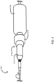
- FIG. 1 provides a schematic illustrating a system 100 in accordance with some embodiments.
- the system 100 includes a console 110 coupled to a catheter assembly 160, which system 100 is configured for modifying intravascular lesions including crossing the intravascular lesions, ablating the intravascular lesions, or a combination of crossing and ablating the intravascular lesions.
- the system 100 includes the console 110.
- the console 110 provides to the system operator an instrument for monitoring and controlling the system 100 and various sub-systems and functions of the system 100.
- the console 110 includes an ultrasound-producing mechanism including an ultrasound generator 120 and an ultrasound transducer 130.
- the console 110 includes the ultrasound generator 120
- the catheter assembly 160 includes the ultrasound transducer 130
- the ultrasound-producing mechanism is divided between the console 110 and the catheter assembly 160.
- the ultrasound-producing mechanism is configured to convert an electric current into vibrational energy.
- the ultrasound generator 120 is configured to convert an alternating electric current (e.g., a current associated with mains electricity) into a high-frequency current (e.g., a current with a frequency commensurate with the operating frequency of the ultrasound transducer 130), and the ultrasound transducer 130, in turn, is configured to convert the high-frequency current into the vibrational energy (e.g., > 20 kHz such as 20.5 kHz ⁇ 500 Hz).
- an alternating electric current e.g., a current associated with mains electricity
- a high-frequency current e.g., a current with a frequency commensurate with the operating frequency of the ultrasound transducer 130
- the ultrasound transducer 130 in turn, is configured to convert the high-frequency current into the vibrational energy (e.g., > 20 kHz such as 20.5 kHz ⁇ 500 Hz).
- the console 110 optionally further includes a foot switch 140 configured to activate and deactivate the system 100 such as activate and deactivate at least the ultrasound-producing mechanism and any components thereof or any components coupled thereto.
- the foot switch 140 is used to activate or deactivate the system 100, thereby activating or deactivating components of the ultrasound-producing mechanism such as the ultrasound transducer 130; components coupled to the ultrasound-producing mechanism, such as a core wire 384 and a tip or tip member 186 of the core wire 384 (see FIGS. 3A and 3B ); or combinations thereof.
- the console 110 optionally further includes an injector 150 configured to inject an irrigant into an irrigation port 172 of the catheter assembly 160.
- the irrigant includes, for example, a sterile liquid (e.g., water, saline, heparinized saline, etc.) for irrigating an anatomical area undergoing an intravascular-lesion-modifying procedure (e.g., crossing an intravascular lesion, ablating an intravascular lesion, etc.), for cooling the core wire 384 of the catheter assembly 160, or a combination thereof.
- a sterile liquid e.g., water, saline, heparinized saline, etc.
- an intravascular-lesion-modifying procedure e.g., crossing an intravascular lesion, ablating an intravascular lesion, etc.
- the console 110 optionally further includes both the foot switch 140 and the injector 150.
- the foot switch 140 can be further configured to activate and deactivate the injector 150 when the system 100 is respectively activated and deactivated with the foot switch 140.
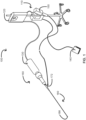
- FIG. 2 provides a schematic illustrating the catheter assembly 160 in accordance with some embodiments.
- the catheter assembly 160 includes a housing 270 coupled to a catheter body 180 ( see FIG. 1 ) including a sheath 282, the core wire 384 ( see FIGS. 3A and 3B ) disposed in a lumen of the sheath 282, and the tip or tip member 186, which catheter assembly 160 is configured for modifying intravascular lesions including crossing the intravascular lesions, ablating the intravascular lesions, or a combination of crossing and ablating the intravascular lesions.
- the housing 270 includes a hub 274 and a lock collar 276 for locking the housing 270 onto the ultrasound transducer 130.
- the irrigation port 172 is not shown in FIG. 2 , as the irrigation port 172 is optional in some embodiments.
- Locking the housing 270 onto the ultrasound transducer 130 ensures a proximal end of the core wire 384 is sufficiently vibrationally coupled to the ultrasound transducer 130 for modifying intravascular lesions.
- the proximal end of the core wire 384 is vibrationally coupled to the ultrasound transducer 130 by a sonic connector 385 (see FIGS.
- the catheter assembly 160 alternatively includes the ultrasound transducer 130, which divides the ultrasound-producing mechanism between the console 110 and the catheter assembly 160.
- the housing 270 further includes the ultrasound transducer 130 disposed therein at the proximal end of the core wire 384, thereby obviating the lock collar 274 shown in FIG. 2 .
- a working length of a distal end portion of the core wire 384 beyond the sheath 282 or the lumen of the sheath 282 is configured to displace for intravascular lesion modification.
- the displacement includes at least longitudinal, transverse, or longitudinal and transverse displacement in accordance with a profile of the core wire 384 and the vibrational energy (e.g., > 20 kHz such as 20.5 kHz ⁇ 500 Hz).
- Longitudinal displacement of the working length of the core wire 384 results in micromotion such as cavitation, and transverse displacement of the working length of the core wire 384 results in macromotion.
- the micromotion is used to cross intravascular lesions.
- the macromotion coupled with the micromotion is used to ablate intravascular lesions, thereby breaking the lesions into minute fragments and restoring patency and blood flow.
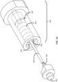
- FIG. 3A provides a schematic illustrating an oblique view of a cartridge 390 including a damping mechanism 392 in accordance with some embodiments.
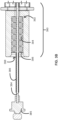
- FIG. 3B provides a schematic illustrating a cross-sectional view of the cartridge 390 including the damping mechanism 392 of FIG. 3A .
- the damping mechanism 392 includes a gasket system 394 configured to exert a compressive force around a proximal end portion of the core wire 384 and a retainer 396 configured to retain the gasket system 394 within a damping-mechanism bore 398 of the cartridge 390 of the catheter assembly 160.
- the gasket system 394 includes a number of O-rings, which range from 1 O-ring to 12 O-rings, including 2 to 10 O-rings, such as 2 to 6 O-rings, for example, 2 to 4 O-rings. In some embodiments, for example, the number of O-rings is 2, 4, 6, or 8 O-rings.
- the O-rings are axially compressed and retained in the damping-mechanism bore 398 by the retainer 396 (e.g., a washer such as a retaining washer, for example, an external star washer).
- Axial compression of the O-rings by the retainer 396 generates a radial compression by an inner wall of the damping-mechanism bore 398 on the core wire 384 sufficient to damp a number of degrees of freedom of vibrational energy provided by the ultrasound-producing mechanism not needed for modifying intravascular lesions.
- transverse-wave-producing vibrational energy about the proximal end portion of the core wire 384 can be damped in favor of the longitudinal-wave-producing vibrational energy.
- the gasket system 394 prevents irrigation backflow of the irrigant through the catheter assembly 160 such as through the damping mechanism 392 and into the ultrasound transducer 130 of the ultrasound-producing mechanism.
- the damping mechanism 392 further includes a sleeve 386 around the core wire 384.
- the sleeve 386 is around at least the proximal end portion of the core wire 384 between the sonic connector 385 and the retainer 396. If not encased by the sleeve 386, the core wire 384 would include an exposed portion of the proximal end portion of the core wire 384 between the sonic connector 385 and the retainer 396.
- the sleeve 386 around the proximal end portion of the core wire 384 between the sonic connector 385 and the retainer 396 prevents fatigue of the core wire 384.
- the sleeve 386 can be further around at least the proximal end portion of the core wire 384 within the damping mechanism 392, as well as around the core wire 384 distal to the damping mechanism 392 up to at least a length of the core wire 384 at which the working length of the core wire 384 begins.
- the sleeve 386 around the core wire 384 encases the core wire 384 with an engineering fit selected from a clearance fit, a transition fit, and an interference fit.
- the clearance fit is a fairly loose fit that enables the core wire 384 to freely rotate or slide within the sleeve 386; the transition fit firmly holds the core wire 384 in place within the sleeve 386, but not so firmly that the core wire 384 cannot be removed from the sleeve 386; and the interference fit securely holds the core wire 384 in place within the sleeve 386 such that the core wire 384 cannot be removed from the sleeve 386 without damaging the core wire 384, the sleeve 386, or both.
- the sleeve 386 encases the core wire 384 with a transition fit or an interference fit.
- the transition fit and the interference fit are created by, for example, heat-shrinking a suitably sized sleeve for the desired fit about the core wire 384 during assembly of the catheter assembly 160.
- the sleeve 386 around the core wire 384 is a polymeric sleeve such as a polytetrafluoroethylene (“PTFE”) sleeve.
- PTFE polytetrafluoroethylene
- Heat in the damping mechanism 392 of an activated catheter assembly can build up quickly, particularly in disposable or single-use disposable catheter assemblies such as the catheter assembly 160 in some embodiments. Such disposable catheter assemblies cannot use typical heat exchange systems such as pipes, pumps, fans, or combinations thereof.
- temperature-measuring devices for the damping mechanism 392 such as thermocouples, on-board microprocessors, or printed circuit boards are cost prohibitive.
- the damping mechanism 392 can be centered over a vibrational node of the core wire 384, or the core wire 384 can be adjusted such that the damping mechanism 392 is over a vibrational node of the core wire 384.
- heat sinks for catheter assemblies such as the heat sinks provided herein are more effective than centering alone at reducing the heat, reducing the temperature in activated catheter assemblies by at least about 80 °F.
- FIG. 4 provides a schematic illustrating a cross-sectional view of the damping mechanism 392 and a first heat sink 410 in accordance with some embodiments.
- the heat sink 410 includes a first sleeve 412 around the gasket system 392 and a second sleeve 414 around the first sleeve 412.
- the first sleeve 412 is of a first material having a first thermal conductivity
- the second sleeve 414 is of a second material having a second thermal conductivity greater than the first thermal conductivity.
- the first material of the first sleeve 412 can be a polymer such as polycarbonate
- the second material of the second sleeve 414 can be a different polymer (e.g., polyetherimide ["PEI"]), a metal (e.g., stainless steel), or an alloy.
- a radially oriented thermal gradient, or a thermal gradient vector field, is thereby established from the gasket system 392, through the first sleeve 412, through the second sleeve 414, and into a fluid medium (e.g., air within the housing 270) for conducting heat away from the damping mechanism 392.
- the thermal conductivity and thermal capacity of the heat sink 410 is such that the catheter assembly 160 can be operated for at least 5, 10, 15, 20, 25, or 30 minutes for modifying intravascular lesions.
- FIG. 5A provides a schematic illustrating a cross-sectional view of the damping mechanism 392 and a second heat sink 510A in accordance with some embodiments.
- FIG. 5B provides a schematic illustrating a cross-sectional view of the damping mechanism 392 and a third heat sink 510B in accordance with some embodiments.
- the heat sink 510A includes a first sleeve 512 around the gasket system 392 and a second sleeve 514A around the first sleeve 512.
- the heat sink 510B includes the first sleeve 512 around 2the gasket system 392 and a second sleeve 514B around the first sleeve 512.
- the second sleeve 514A of the heat sink 510A and the second sleeve 514B of the heat sink 510B are configured as passive heat exchangers.
- the second sleeve 514A is configured as a passive heat exchanger with a number of circumferential fins arranged along a length of the second sleeve 514A configured to dissipate heat from the damping mechanism 392.
- the second sleeve 514B is configured as a passive heat exchanger with a number of longitudinal fins arranged around a circumference of the second sleeve 514B configured to dissipate heat from the damping mechanism 392.
- the second sleeve 514A and the second sleeve 514B represent just two passive heat exchangers with a number of fins configured to dissipate heat from the damping mechanism 392.
- the fins can be, for example, diagonal or helical, crosshatched, or segmented to form pins or more substantial protrusions.
- the first sleeve 512 is of a first material having a first thermal conductivity
- the second sleeve 514A or the second sleeve 514B is of a second material having a second thermal conductivity greater than the first thermal conductivity.
- the first material also has a first specific heat capacity
- the second material also has a second specific heat capacity, which can be greater or less than the first specific heat capacity.
- the first material of the first sleeve 512 can be a polymer such as polycarbonate, and the second material of the second sleeve 514A or the second sleeve 514B can be a different polymer (e.g., PEI), a metal (e.g., stainless steel, aluminum), or an alloy (e.g., aluminum alloy).
- PEI polymer
- metal e.g., stainless steel, aluminum
- an alloy e.g., aluminum alloy
- a radially oriented thermal gradient, or a thermal gradient vector field is thereby established from the gasket system 392, through the first sleeve 512, through the second sleeve 514A or the second sleeve 514B, and into a fluid medium (e.g., air within the housing 270) for conducting heat away from the damping mechanism 392.
- a fluid medium e.g., air within the housing 270
- the thermal conductivity and heat capacity of the heat sink 510A or 510B along with a number of fins, dimensions of the fins, pitch of the fins, or the like of the heat exchanger is sufficient for operating the catheter assembly 160 for at least 1, 2, 3, 4, 5, 10, 15, 20, 25, or 30 minutes for modifying intravascular lesions. Because there can be little convection inside the housing 270 of the catheter assembly 270, the fins of the heat sink 510A or 510B are sized as large as needed to achieve a desired operation time for the catheter assembly 160 while maintaining ease of use for an operator of the catheter assembly 160.
- FIG. 6 provides a schematic illustrating a cross-sectional view of the damping mechanism 392 and a fourth heat sink 610 in accordance with some embodiments.
- the heat sink 610 includes a first annulus 612 at a first end (e.g., proximal end) of the gasket system 392, a second annulus 613 at a second, opposing end (e.g., distal end) of the gasket system 392.
- the heat sink 610 further includes a number of longitudinal members 616 set in the annuli 612 and 613 around a circumference of the gasket system 392 configured to conduct and dissipate heat from the damping mechanism 392.
- the heat sink 610 further includes a number of struts 617 set in the annuli 612 and 613 radially outward from the number of longitudinal members 616 for additional structural integrity.
- the annuli 612 and 613 are of a first material having a first thermal conductivity
- the longitudinal members 616 are of a second material having a second thermal conductivity greater than the first thermal conductivity.
- the first material also has a first specific heat capacity
- the second material also has a second specific heat capacity, which can be greater or less than the first specific heat capacity.
- the first material of the annuli 612 and 613 can be a polymer such as polycarbonate
- the second material of the longitudinal members 616 can be a different polymer (e.g., PEI), a metal (e.g., stainless steel, aluminum), or an alloy (e.g., aluminum alloy).
- the thermal conductivity and heat capacity of the heat sink 610 is such that the catheter assembly 160 can be operated for at least 1, 2, 3, 4, 5, 10, 15, 20, 25, or 30 minutes for modifying intravascular lesions.
- the number of struts 617 such as 4, 6, or 8 struts, when present, is sufficient to provide structural integrity without interfering with the efficiency of the longitudinal members 616 in dissipating heat from the damping mechanism 392.
- FIG. 7 provides a schematic illustrating a cross-sectional view of the damping mechanism 392 and a fifth heat sink 710 in accordance with some embodiments.
- the heat sink 710 includes a first sleeve 712 around the gasket system 392 and a second sleeve 714 around the first sleeve 712.
- the first sleeve 712 includes a fillable cavity 715 formed by a circumferential groove around the first sleeve 712.
- the cavity 715 can simply be filled with air.
- the cavity 715 can be filled, in whole or in part, with a coolant of one or more materials featuring a different specific heat capacity, a different thermal conductivity, or a different specific heat capacity and a different thermal conductivity than air.
- the coolant can be selected from water, a glycol (e.g., ethylene glycol, diethylene glycol, propylene glycol, etc.), a water-glycol mixture, a mineral oil, a silicone oil, a heat-storage material, and combinations thereof.
- the heat-storage material can be PX-52 by Rubitherm Technologies GmbH of Berlin, Germany, which includes a phase change material on a solid support (e.g., silica).
- Heat from the damping mechanism 392 is conducted to the cavity 715 in accordance with a radially oriented thermal gradient and absorbed by the coolant in accordance with its specific heat capacity.
- heat from the damping mechanism 392 is absorbed by the phase change material to melt the phase change material instead of increasing the temperature of the heat-storage material.
- a benefit of the heat-storage material is that it does not melt but rather congeals as a result of the phase change material's attachment to the solid support. This makes the heat-storage material easier to contain in the cavity 715.
- the second sleeve 714 around the first sleeve 712 provides a seal for the cavity 715 and any contents disposed in the cavity 715.
- the first sleeve 712 is of a first material having a first thermal conductivity
- the second sleeve 714 is of a second material optionally having a second thermal conductivity greater than the first thermal conductivity.
- the first material also has a first specific heat capacity
- the second material also has a second specific heat capacity, which can be greater or less than the first specific heat capacity.
- the first material of the first sleeve 712 can be a polymer such as polycarbonate
- the second material of the second sleeve 714 can be a same polymer or a different polymer (e.g., PEI), a metal (e.g., stainless steel, aluminum), or an alloy (e.g., aluminum alloy).
- a radially oriented thermal gradient, or a thermal gradient vector field, can be established from the gasket system 392, through the first sleeve 712, through the cavity 715 including any coolants, through the second sleeve 714, and into a fluid medium (e.g., air within the housing 270) for conducting heat away from the damping mechanism 392.
- the thermal conductivity and heat capacity of the heat sink 710 is such that the catheter assembly 160 can be operated for at least 1, 2, 3, 4, 5, 10, 15, 20, 25, or 30 minutes for modifying intravascular lesions.
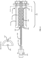
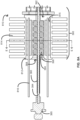
- FIG. 8A provides a schematic illustrating a cross-sectional view of the damping mechanism 392 and a sixth heat sink 810 in accordance with some embodiments.
- the heat sink 810 is an example of a heat sink incorporating a number of features of the heat sinks 510A, 610, and 710.
- the heat sink 810 includes a first sleeve 812 around the gasket system 392 and a second sleeve 814 fashioned as a passive heat exchanger around the first sleeve 812.
- the first sleeve 812 includes a fillable cavity 815 formed by a circumferential groove around the first sleeve 812, which can be filled with any coolant set forth herein, and for which the second sleeve 814 provides a seal.
- the heat sink 810 includes a number of longitudinal members 816 set in ends of the first sleeve 812 around a circumference of the gasket system 392.
- the longitudinal members 816 are configured to extend from the heat sink 810 toward the proximal end of the core wire 384 to draw heat away from the heat sink 810.
- the longitudinal members 816 are also configured to embed in any coolant in the cavity 815.
- the longitudinal members are configured to draw heat away from the heat-storage material such as latent heat when the heat-storage material is in its congealed state, thereby providing stable responses for heat spikes and drawing even more heat away from the damping mechanism 392 when the catheter assembly 160 is deactivated during intermittent breaks in an intravascular-lesion-modifying procedure.
- the heat sink 810 configures the heat sink 810 to conduct and dissipate heat from the damping mechanism 392.
- the thermal conductivity and heat capacity of the heat sink 810 is such that the catheter assembly 160 can be operated for at least 1, 2, 3, 4, 5, 10, 15, 20, 25, or 30 minutes for modifying intravascular lesions.
- Any heat sink of the heat sinks 410, 510A, 510B, 610, 710, and 810 can be modified in any of a number of ways to increase or decrease operation times for the catheter assembly 160 including the heat sink. This is to balance manufacturing costs with expected procedure times for the catheter assembly 160, which catheter assembly 160 is also a disposable or single-use disposable catheter assembly 160 in some embodiments. Not only can a heat sink of the heat sinks 410, 510A, 510B, 610, 710, and 810 be modified with features of any other heat sink of the heat sinks 410, 510A, 510B, 610, 710, and 810, but materials and dimensions (e.g., relative dimensions) of the heat sink can be modified as well.
- the second sleeve 414 of the first heat sink 410 is shown in FIG. 4 as having a same thickness as the first sleeve 412, the second sleeve 414 can be at least 2, 3, 4, or 5 times thicker in some embodiments to increase the heat capacity of the second sleeve 414 and the heat sink 410.
- An increase in the heat capacity of the second sleeve 414 can alternatively or additionally be accomplished by using a material with a higher specific heat capacity than the example materials given for the second material of the second sleeve 414.
- the cavity 715 can be at least as thick as the damping-mechanism bore 398 or 2, 3, 4, or 5 times thicker than the damping-mechanism bore 398 in some embodiments to increase the heat capacity of the cavity 715 and the heat sink 710.
- An increase in the heat capacity of the cavity 715 can alternatively or additionally be accomplished by using a coolant with a higher specific heat capacity than the example coolants given for the cavity 715. In general for all heat sinks provided herein, it is desired to keep a temperature below about 200 °F in the housing 270 of the catheter assembly 160 such as between the damping mechanism 392 and the housing 270.
- Making the catheter assembly 160 including the sonic connector 385 at the proximal end of the core wire 384, the damping mechanism 392 around the proximal end portion of the core wire 384, and any heat sink of the heat sinks 410, 510A, 510B, 710, and 810 includes molding a cartridge 390 including a damping-mechanism bore 398 in a first sleeve such as the first sleeve 412, 512, 712, or 812; disposing a second sleeve such as the second sleeve 412, 512A, 512B, 712, or 812 over the first sleeve to form the heat sink including the first and second sleeves; disposing the core wire 384 through a center of the damping-mechanism bore 398 coincident with a rotational axis of the cartridge 390; disposing the number of O-rings in the damping-mechanism bore 398 around the core wire 384; and fixing the retainer 396 in
- the steps of molding the cartridge 390 with the first sleeve and disposing the second sleeve over the first sleeve are modified such that molding the cartridge 390 includes molding the cartridge 390 including the second annulus 613; molding the first annulus 612; and disposing or otherwise setting at least the number of longitudinal members 616 in the annuli 612 and 613 to form the damping-mechanism bore 398, or an analog thereof, and the heat sink 610.
- Molding the cartridge 390 includes molding the cartridge 390 by way of compression molding, injection molding, thermoforming, or a combination thereof.
- the core wire 384 Prior to disposing the core wire 384 through the center of the damping-mechanism bore 398, the core wire 384 is optionally disposed in a heat-shrinkable polymeric sleeve (e.g., polytetrafluoroethylene ["PTFE"]) and uniformly heated to shrink the heat-shrinkable polymeric sleeve around the core wire 384 to form the polymeric sleeve 386 around the core wire 384.
- a heat-shrinkable polymeric sleeve e.g., polytetrafluoroethylene ["PTFE"
- Fixing the retainer 396 in the proximal end of the damping-mechanism bore 398 generates a radial compressive force on the core wire 384.
- the radial compressive force occurs from an axial compressive force on the O-rings resulting from axially pressing the O-rings against a distal end of the damping-mechanism bore 398 with the retainer 396 in the proximal end of the damping-mechanism bore 398.
- the axial compressive force in turn, generates the radial compressive force on the core wire 384 via radial expansion of the O-rings, thereby, radially pressing the O-rings against an inner wall of the damping-mechanism bore 398 opposing the core wire 384 and the core wire 384 itself.
- the compressive force is sufficient for damping a number of degrees of freedom of vibrational energy in the proximal end portion of the core wire 384. Heat from the damping dissipates through the heat sink.
- Making the catheter assembly 160 includes molding a housing of the catheter assembly 160, and subsequently disposing the cartridge 390 including the damping mechanism 392 around the core wire 384 in the housing to form the catheter assembly 160. Disposing the cartridge 390 in the housing includes connecting the sonic connector 385 of the core wire 384 to the ultrasound-producing mechanism configured to impart the vibrational energy to the proximal end of the core wire 384.
- Advantages of some embodiments of the catheter assembly 160 include, but are not limited to, passive control of heat caused by damping vibrational energy; running times sufficient for modifying intravascular lesions either by crossing, ablating, or a combination of crossing and ablating the intravascular lesions; use of polymers (e.g., polycarbonate) suitable for use in molding such as injection molding; or a combination thereof.
- polymers e.g., polycarbonate
Landscapes
- Health & Medical Sciences (AREA)
- Surgery (AREA)
- Engineering & Computer Science (AREA)
- Life Sciences & Earth Sciences (AREA)
- Biomedical Technology (AREA)
- Molecular Biology (AREA)
- Vascular Medicine (AREA)
- Orthopedic Medicine & Surgery (AREA)
- Mechanical Engineering (AREA)
- Heart & Thoracic Surgery (AREA)
- Medical Informatics (AREA)
- Nuclear Medicine, Radiotherapy & Molecular Imaging (AREA)
- Animal Behavior & Ethology (AREA)
- General Health & Medical Sciences (AREA)
- Public Health (AREA)
- Veterinary Medicine (AREA)
- Surgical Instruments (AREA)
- Ultra Sonic Daignosis Equipment (AREA)
Abstract
Description
- Atherosclerosis is characterized by one or more intravascular lesions formed, in part, of plaque including blood-borne substances such as fat, cholesterol, or calcium. An intravascular lesion such as an arterial lesion can form on a wall of an arterial lumen and build out across the lumen to an opposite arterial wall. A last point of patency often occurs at a boundary between the arterial lesion and the opposite arterial wall. Surgical procedures for atherosclerosis such as atherectomy can be used to restore patency and blood flow impeded by such lesions. However, prolonged running times required of endoluminal devices such as catheters for modification of intravascular lesions can lead to heat-related complications for the endoluminal devices, which, in turn, can lead to complications in the surgical procedures and the patients undergoing the surgical procedures. Provided herein in some embodiments are heat sinks for catheters, as well as systems and methods thereof that address at least the foregoing.
- Provided herein is a catheter assembly including, in some embodiments, a sonic connector at a proximal end of a core wire, a damping mechanism around a proximal end portion of the core wire, and a heat sink connected to the damping mechanism. The sonic connector is configured to couple to an ultrasound-producing mechanism and transmit vibrational energy to the proximal end of the core wire, which core wire includes a distal end portion configured to modify intravascular lesions. The damping mechanism includes a gasket system around the proximal end portion of the core wire in a damping-mechanism bore of the catheter assembly. The damping mechanism is configured to damp the vibrational energy.
- In some embodiments, the heat sink includes a first sleeve around the gasket system and a second sleeve around the first sleeve. The first sleeve is of a first material having a first thermal conductivity, and the second sleeve is of a second material having a second thermal conductivity greater than the first thermal conductivity.
- In some embodiments, the second sleeve is configured as a passive heat exchanger. The heat exchanger includes a number of circumferential fins arranged along a length of the second sleeve configured to dissipate the heat from the damping mechanism. Alternatively, the heat exchanger includes a number of longitudinal fins arranged around a circumference of the second sleeve configured to dissipate the heat from the damping mechanism.
- In some embodiments, the first sleeve includes a cavity formed by a circumferential groove around the first sleeve. The cavity is filled with a coolant, and the second sleeve is disposed over the cavity.
- In some embodiments, the coolant is water, a glycol, a water-glycol mixture, a mineral oil, a silicone oil, or a heat-storage material.
- In some embodiments, the heat sink includes a first annulus at a first end of the gasket system, a second annulus at a second, opposing end of the gasket system, and a number of longitudinal members arranged around a circumference of the gasket system.
- In some embodiments, a center of the gasket system is positioned over a vibrational node of the core wire where the core wire experiences less transverse-wave-producing vibrational energy than an anti-node of the core wire, thereby reducing frictional heating.
- In some embodiments, the gasket system includes a number of axially and radially compressed O-rings in the damping-mechanism bore.
- In some embodiments, a polymeric sleeve is around an exposed portion of the proximal end portion of the core wire between the sonic connector and a retainer configured to retain the O-rings in the damping-mechanism bore.
- In some embodiments, the polymeric sleeve is around the exposed portion of the proximal end portion of the core wire and further around the proximal end portion of the core wire in the damping mechanism.
- In some embodiments, the catheter assembly further includes at least a portion of an ultrasound-producing mechanism including an ultrasound transducer.
- Also provided herein is a system including, in some embodiments, a catheter assembly and an ultrasound-producing mechanism. The catheter assembly includes a sonic connector at a proximal end of a core wire, a damping mechanism around a proximal end portion of the core wire, and a heat sink connected to the damping mechanism. The sonic connector is configured to transmit vibrational energy to the proximal end of the core wire, which core wire includes a distal end portion configured to modify intravascular lesions. The damping mechanism includes a gasket system around the proximal end portion of the core wire in a damping-mechanism bore of the catheter assembly. The damping mechanism is configured to damp the vibrational energy. The ultrasound-producing mechanism includes an ultrasound generator and an ultrasound transducer.
- In some embodiments, the heat sink includes a first sleeve around the gasket system and a second sleeve around the first sleeve. The first sleeve is of a first material having a first thermal conductivity, and the second sleeve is of a second material having a second thermal conductivity greater than the first thermal conductivity.
- In some embodiments, the second sleeve is configured as a passive heat exchanger. The heat exchanger includes a number of circumferential fins arranged along a length of the second sleeve configured to dissipate the heat from the damping mechanism. Alternatively, the heat exchanger includes a number of longitudinal fins arranged around a circumference of the second sleeve configured to dissipate the heat from the damping mechanism.
- In some embodiments, the first sleeve includes a cavity formed by a circumferential groove around the first sleeve. The cavity is filled with a coolant selected from water, a glycol, a water-glycol mixture, a mineral oil, a silicone oil, and a heat-storage material. The second sleeve is disposed over the cavity sealing the coolant in the cavity.
- In some embodiments, the heat sink includes a first annulus at a first end of the gasket system, a second annulus at a second, opposing end of the gasket system, and a number of longitudinal members arranged around a circumference of the gasket system.
- In some embodiments, the gasket system includes a number of axially and radially compressed O-rings in the damping-mechanism bore.
- In some embodiments, a polymeric sleeve is around an exposed portion of the proximal end portion of the core wire between the sonic connector and a retainer configured to retain the O-rings in the damping-mechanism bore.
- In some embodiments, the polymeric sleeve is around the exposed portion of the proximal end portion of the core wire and further around the proximal end portion of the core wire in the damping mechanism.
- In some embodiments, the system further includes a console including a foot switch and the ultrasound-producing mechanism including both the ultrasound generator and the ultrasound transducer. The foot switch is configured to activate and deactivate the ultrasound-producing mechanism.
- In some embodiments, the system further includes a console including a foot switch and only the ultrasound generator of the ultrasound-producing mechanism. The catheter assembly further includes the ultrasound transducer of the ultrasound-producing mechanism. The foot switch is configured to activate and deactivate the ultrasound-producing mechanism.
- Also provided herein is a method for making a catheter assembly including, in some embodiments, molding a cartridge including a damping-mechanism bore in a first sleeve; disposing a second sleeve over the first sleeve to form a heat sink including the first and second sleeves; disposing a core wire through a center of the damping-mechanism bore coincident with a rotational axis of the cartridge; disposing a number of O-rings in the damping-mechanism bore around the core wire; and fixing a retainer in a proximal end of the damping-mechanism bore to form a damping mechanism around the core wire. Fixing the retainer in the proximal end of the damping-mechanism bore generates a compressive force on the core wire. The compressive force is sufficient for damping vibrational energy in a proximal end portion of the core wire.
- In some embodiments, the method further includes disposing the core wire in a polymeric sleeve; and uniformly heating the polymeric sleeve to shrink the polymeric sleeve around the core wire before disposing the core wire through the center of the damping-mechanism bore.
- In some embodiments, the method further includes molding a housing of a catheter assembly; disposing the cartridge with the damping mechanism and the heat sink in the housing of the catheter assembly; and connecting a proximal end of the core wire to an ultrasound-producing mechanism.
-
-
FIG. 1 provides a schematic illustrating a system in accordance with some embodiments. -
FIG. 2 provides a schematic illustrating a catheter assembly in accordance with some embodiments. -
FIG. 3A provides a schematic illustrating an oblique view of cartridge including a damping mechanism in accordance with some embodiments. -
FIG. 3B provides a schematic illustrating a cross-sectional view of the cartridge including the damping mechanism ofFIG. 3A . -
FIG. 4 provides a schematic illustrating a cross-sectional view of a damping mechanism and a first heat sink in accordance with some embodiments. -
FIG. 5A provides a schematic illustrating a cross-sectional view of a damping mechanism and a second heat sink in accordance with some embodiments. -
FIG. 5B provides a schematic illustrating a cross-sectional view of a damping mechanism and a third heat sink in accordance with some embodiments. -
FIG. 6 provides a schematic illustrating a cross-sectional view of a damping mechanism and a fourth heat sink in accordance with some embodiments. -
FIG. 7 provides a schematic illustrating a cross-sectional view of a damping mechanism and a fifth heat sink in accordance with some embodiments. -
FIG. 8A provides a schematic illustrating a cross-sectional view of a damping mechanism and a sixth heat sink in accordance with some embodiments. -
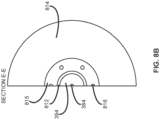
FIG. 8B provides a schematic illustrating a cross-sectional view (Section E-E) of the damping mechanism and the sixth heat sink ofFIG. 8A . - Before some particular embodiments are provided in greater detail, it should be understood that the particular embodiments provided herein do not limit the scope of the concepts provided herein. It should also be understood that a particular embodiment provided herein can have features that can be readily separated from the particular embodiment and optionally combined with or substituted for features of any of a number of other embodiments provided herein.
- Regarding terms used herein, it should also be understood the terms are for the purpose of describing some particular embodiments, and the terms do not limit the scope of the concepts provided herein. Ordinal numbers (e.g., first, second, third, etc.) are generally used to distinguish or identify different features or steps in a group of features or steps, and do not supply a serial or numerical limitation. For example, "first," "second," and "third" features or steps need not necessarily appear in that order, and the particular embodiments including such features or steps need not necessarily be limited to the three features or steps. Labels such as "left," "right," "front," "back," "top," "bottom," "forward," "reverse," "clockwise," "counter clockwise," "up," "down," or other similar terms such as "upper," "lower," "aft," "fore," "vertical," "horizontal," "proximal," "distal," and the like are used for convenience and are not intended to imply, for example, any particular fixed location, orientation, or direction. Instead, such labels are used to reflect, for example, relative location, orientation, or directions. Singular forms of "a," "an," and "the" include plural references unless the context clearly dictates otherwise.
- With respect to "proximal," a "proximal portion" or a "proximal end portion" of, for example, a catheter provided herein includes a portion of the catheter intended to be near a clinician when the catheter is used on a patient. Likewise, a "proximal length" of, for example, the catheter includes a length of the catheter intended to be near the clinician when the catheter is used on the patient. A "proximal end" of, for example, the catheter includes an end of the catheter intended to be near the clinician when the catheter is used on the patient. The proximal portion, the proximal end portion, or the proximal length of the catheter can include the proximal end of the catheter; however, the proximal portion, the proximal end portion, or the proximal length of the catheter need not include the proximal end of the catheter. That is, unless context suggests otherwise, the proximal portion, the proximal end portion, or the proximal length of the catheter is not a terminal portion or terminal length of the catheter.
- With respect to "distal," a "distal portion" or a "distal end portion" of, for example, a catheter provided herein includes a portion of the catheter intended to be near or in a patient when the catheter is used on the patient. Likewise, a "distal length" of, for example, the catheter includes a length of the catheter intended to be near or in the patient when the catheter is used on the patient. A "distal end" of, for example, the catheter includes an end of the catheter intended to be near or in the patient when the catheter is used on the patient. The distal portion, the distal end portion, or the distal length of the catheter can include the distal end of the catheter; however, the distal portion, the distal end portion, or the distal length of the catheter need not include the distal end of the catheter. That is, unless context suggests otherwise, the distal portion, the distal end portion, or the distal length of the catheter is not a terminal portion or terminal length of the catheter.
- The term "heat capacity" is used in association with a feature (e.g., the second sleeve 414) or a combination of features (e.g., the first heat sink 410) and its ability or resistance to change temperature from applied heat, which is an extrinsic physical property depending upon at least a size of the feature or the combination of features.
- The term "specific heat capacity" is used in association with a material (e.g., the second material of the second sleeve 414) and its ability or resistance to change temperature from applied heat, which is an intrinsic physical property when the amount of the material is taken into consideration.
- Unless defined otherwise, all technical and scientific terms used herein have the same meaning as commonly understood by those of ordinary skill in the art.
- Atherosclerosis is characterized by one or more intravascular lesions formed, in part, of plaque including blood-borne substances such as fat, cholesterol, or calcium. An intravascular lesion such as an arterial lesion can form on a wall of an arterial lumen and build out across the lumen to an opposite arterial wall. A last point of patency often occurs at a boundary between the arterial lesion and the opposite arterial wall. Surgical procedures for atherosclerosis such as atherectomy can be used to restore patency and blood flow impeded by such lesions. However, prolonged running times required of endoluminal devices such as catheters for modification of intravascular lesions can lead to heat-related complications for the endoluminal devices, which, in turn, can lead to complications in the surgical procedures and the patients undergoing the surgical procedures. Provided herein in some embodiments are heat sinks for catheters, as well as systems and methods thereof that address at least the foregoing.
-
FIG. 1 provides a schematic illustrating asystem 100 in accordance with some embodiments. Thesystem 100 includes aconsole 110 coupled to acatheter assembly 160, whichsystem 100 is configured for modifying intravascular lesions including crossing the intravascular lesions, ablating the intravascular lesions, or a combination of crossing and ablating the intravascular lesions. - As shown in
FIG. 1 , thesystem 100 includes theconsole 110. Theconsole 110 provides to the system operator an instrument for monitoring and controlling thesystem 100 and various sub-systems and functions of thesystem 100. Theconsole 110 includes an ultrasound-producing mechanism including anultrasound generator 120 and anultrasound transducer 130. Alternatively, theconsole 110 includes theultrasound generator 120, thecatheter assembly 160 includes theultrasound transducer 130, and the ultrasound-producing mechanism is divided between theconsole 110 and thecatheter assembly 160. The ultrasound-producing mechanism is configured to convert an electric current into vibrational energy. For example, theultrasound generator 120 is configured to convert an alternating electric current (e.g., a current associated with mains electricity) into a high-frequency current (e.g., a current with a frequency commensurate with the operating frequency of the ultrasound transducer 130), and theultrasound transducer 130, in turn, is configured to convert the high-frequency current into the vibrational energy (e.g., > 20 kHz such as 20.5 kHz ± 500 Hz). - The
console 110 optionally further includes afoot switch 140 configured to activate and deactivate thesystem 100 such as activate and deactivate at least the ultrasound-producing mechanism and any components thereof or any components coupled thereto. When thesystem 100 is powered, thefoot switch 140 is used to activate or deactivate thesystem 100, thereby activating or deactivating components of the ultrasound-producing mechanism such as theultrasound transducer 130; components coupled to the ultrasound-producing mechanism, such as acore wire 384 and a tip ortip member 186 of the core wire 384 (seeFIGS. 3A and3B ); or combinations thereof. - The
console 110 optionally further includes aninjector 150 configured to inject an irrigant into anirrigation port 172 of thecatheter assembly 160. The irrigant includes, for example, a sterile liquid (e.g., water, saline, heparinized saline, etc.) for irrigating an anatomical area undergoing an intravascular-lesion-modifying procedure (e.g., crossing an intravascular lesion, ablating an intravascular lesion, etc.), for cooling thecore wire 384 of thecatheter assembly 160, or a combination thereof. - The
console 110 optionally further includes both thefoot switch 140 and theinjector 150. In such embodiments, thefoot switch 140 can be further configured to activate and deactivate theinjector 150 when thesystem 100 is respectively activated and deactivated with thefoot switch 140. -
FIG. 2 provides a schematic illustrating thecatheter assembly 160 in accordance with some embodiments. Thecatheter assembly 160 includes ahousing 270 coupled to a catheter body 180 (seeFIG. 1 ) including asheath 282, the core wire 384 (seeFIGS. 3A and3B ) disposed in a lumen of thesheath 282, and the tip ortip member 186, whichcatheter assembly 160 is configured for modifying intravascular lesions including crossing the intravascular lesions, ablating the intravascular lesions, or a combination of crossing and ablating the intravascular lesions. - As shown in
FIG. 2 , thehousing 270 includes ahub 274 and alock collar 276 for locking thehousing 270 onto theultrasound transducer 130. (Theirrigation port 172 is not shown inFIG. 2 , as theirrigation port 172 is optional in some embodiments.) Locking thehousing 270 onto theultrasound transducer 130 ensures a proximal end of thecore wire 384 is sufficiently vibrationally coupled to theultrasound transducer 130 for modifying intravascular lesions. The proximal end of thecore wire 384 is vibrationally coupled to theultrasound transducer 130 by a sonic connector 385 (seeFIGS. 3A and3B ), optionally through an intervening ultrasound horn, and a distal end of thecore wire 384 is vibrationally coupled to a lesion-modifyingtip 186 fashioned from the distal end of thecore wire 384 or a lesion-modifyingtip member 186 coupled to the distal end of thecore wire 384. As such, thesonic connector 385 is configured to impart or otherwise transfer the vibrational energy from theultrasound transducer 130 to thecore wire 384. And thecore wire 384 is configured to impart or otherwise transfer the vibrational energy to the tip ortip member 186 of thecore wire 384 for modifying intravascular lesions. Again, thecatheter assembly 160 alternatively includes theultrasound transducer 130, which divides the ultrasound-producing mechanism between theconsole 110 and thecatheter assembly 160. In such embodiments, thehousing 270 further includes theultrasound transducer 130 disposed therein at the proximal end of thecore wire 384, thereby obviating thelock collar 274 shown inFIG. 2 . - A working length of a distal end portion of the
core wire 384 beyond thesheath 282 or the lumen of thesheath 282 is configured to displace for intravascular lesion modification. The displacement includes at least longitudinal, transverse, or longitudinal and transverse displacement in accordance with a profile of thecore wire 384 and the vibrational energy (e.g., > 20 kHz such as 20.5 kHz ± 500 Hz). Longitudinal displacement of the working length of thecore wire 384 results in micromotion such as cavitation, and transverse displacement of the working length of thecore wire 384 results in macromotion. The micromotion is used to cross intravascular lesions. The macromotion coupled with the micromotion is used to ablate intravascular lesions, thereby breaking the lesions into minute fragments and restoring patency and blood flow. -
FIG. 3A provides a schematic illustrating an oblique view of acartridge 390 including a dampingmechanism 392 in accordance with some embodiments.FIG. 3B provides a schematic illustrating a cross-sectional view of thecartridge 390 including the dampingmechanism 392 ofFIG. 3A . The dampingmechanism 392 includes agasket system 394 configured to exert a compressive force around a proximal end portion of thecore wire 384 and aretainer 396 configured to retain thegasket system 394 within a damping-mechanism bore 398 of thecartridge 390 of thecatheter assembly 160. - As shown in
FIGS. 3A and3B , thegasket system 394 includes a number of O-rings, which range from 1 O-ring to 12 O-rings, including 2 to 10 O-rings, such as 2 to 6 O-rings, for example, 2 to 4 O-rings. In some embodiments, for example, the number of O-rings is 2, 4, 6, or 8 O-rings. The O-rings are axially compressed and retained in the damping-mechanism bore 398 by the retainer 396 (e.g., a washer such as a retaining washer, for example, an external star washer). Axial compression of the O-rings by theretainer 396 generates a radial compression by an inner wall of the damping-mechanism bore 398 on thecore wire 384 sufficient to damp a number of degrees of freedom of vibrational energy provided by the ultrasound-producing mechanism not needed for modifying intravascular lesions. For example, transverse-wave-producing vibrational energy about the proximal end portion of thecore wire 384 can be damped in favor of the longitudinal-wave-producing vibrational energy. - In embodiments of the
system 100 including theinjector 150, thegasket system 394 prevents irrigation backflow of the irrigant through thecatheter assembly 160 such as through the dampingmechanism 392 and into theultrasound transducer 130 of the ultrasound-producing mechanism. - The damping
mechanism 392 further includes asleeve 386 around thecore wire 384. Thesleeve 386 is around at least the proximal end portion of thecore wire 384 between thesonic connector 385 and theretainer 396. If not encased by thesleeve 386, thecore wire 384 would include an exposed portion of the proximal end portion of thecore wire 384 between thesonic connector 385 and theretainer 396. Thesleeve 386 around the proximal end portion of thecore wire 384 between thesonic connector 385 and theretainer 396 prevents fatigue of thecore wire 384. Thesleeve 386 can be further around at least the proximal end portion of thecore wire 384 within the dampingmechanism 392, as well as around thecore wire 384 distal to the dampingmechanism 392 up to at least a length of thecore wire 384 at which the working length of thecore wire 384 begins. - The
sleeve 386 around thecore wire 384 encases thecore wire 384 with an engineering fit selected from a clearance fit, a transition fit, and an interference fit. The clearance fit is a fairly loose fit that enables thecore wire 384 to freely rotate or slide within thesleeve 386; the transition fit firmly holds thecore wire 384 in place within thesleeve 386, but not so firmly that thecore wire 384 cannot be removed from thesleeve 386; and the interference fit securely holds thecore wire 384 in place within thesleeve 386 such that thecore wire 384 cannot be removed from thesleeve 386 without damaging thecore wire 384, thesleeve 386, or both. In some embodiments, thesleeve 386 encases thecore wire 384 with a transition fit or an interference fit. The transition fit and the interference fit are created by, for example, heat-shrinking a suitably sized sleeve for the desired fit about thecore wire 384 during assembly of thecatheter assembly 160. Thesleeve 386 around thecore wire 384 is a polymeric sleeve such as a polytetrafluoroethylene ("PTFE") sleeve. - Heat in the damping
mechanism 392 of an activated catheter assembly can build up quickly, particularly in disposable or single-use disposable catheter assemblies such as thecatheter assembly 160 in some embodiments. Such disposable catheter assemblies cannot use typical heat exchange systems such as pipes, pumps, fans, or combinations thereof. In addition, temperature-measuring devices for the dampingmechanism 392 such as thermocouples, on-board microprocessors, or printed circuit boards are cost prohibitive. The dampingmechanism 392 can be centered over a vibrational node of thecore wire 384, or thecore wire 384 can be adjusted such that the dampingmechanism 392 is over a vibrational node of thecore wire 384. This reduces some heat caused by damping the vibrational energy because the core wire experiences less transverse-wave-producing vibrational energy at the vibrational node of the core wire than at an anti-node of the core wire. However, heat sinks for catheter assemblies such as the heat sinks provided herein are more effective than centering alone at reducing the heat, reducing the temperature in activated catheter assemblies by at least about 80 °F. -
FIG. 4 provides a schematic illustrating a cross-sectional view of the dampingmechanism 392 and afirst heat sink 410 in accordance with some embodiments. Theheat sink 410 includes afirst sleeve 412 around thegasket system 392 and asecond sleeve 414 around thefirst sleeve 412. - The
first sleeve 412 is of a first material having a first thermal conductivity, and thesecond sleeve 414 is of a second material having a second thermal conductivity greater than the first thermal conductivity. The first material of thefirst sleeve 412 can be a polymer such as polycarbonate, and the second material of thesecond sleeve 414 can be a different polymer (e.g., polyetherimide ["PEI"]), a metal (e.g., stainless steel), or an alloy. A radially oriented thermal gradient, or a thermal gradient vector field, is thereby established from thegasket system 392, through thefirst sleeve 412, through thesecond sleeve 414, and into a fluid medium (e.g., air within the housing 270) for conducting heat away from the dampingmechanism 392. The thermal conductivity and thermal capacity of theheat sink 410 is such that thecatheter assembly 160 can be operated for at least 5, 10, 15, 20, 25, or 30 minutes for modifying intravascular lesions. -
FIG. 5A provides a schematic illustrating a cross-sectional view of the dampingmechanism 392 and asecond heat sink 510A in accordance with some embodiments.FIG. 5B provides a schematic illustrating a cross-sectional view of the dampingmechanism 392 and athird heat sink 510B in accordance with some embodiments. Theheat sink 510A includes afirst sleeve 512 around thegasket system 392 and asecond sleeve 514A around thefirst sleeve 512. Likewise, theheat sink 510B includes thefirst sleeve 512 around 2thegasket system 392 and asecond sleeve 514B around thefirst sleeve 512. - As shown in
FIGS. 5A and5B , thesecond sleeve 514A of theheat sink 510A and thesecond sleeve 514B of theheat sink 510B are configured as passive heat exchangers. Thesecond sleeve 514A is configured as a passive heat exchanger with a number of circumferential fins arranged along a length of thesecond sleeve 514A configured to dissipate heat from the dampingmechanism 392. Thesecond sleeve 514B is configured as a passive heat exchanger with a number of longitudinal fins arranged around a circumference of thesecond sleeve 514B configured to dissipate heat from the dampingmechanism 392. Thesecond sleeve 514A and thesecond sleeve 514B represent just two passive heat exchangers with a number of fins configured to dissipate heat from the dampingmechanism 392. Instead of the circumferential fins of thesecond sleeve 514A or the longitudinal fins of thesecond sleeve 514B, the fins can be, for example, diagonal or helical, crosshatched, or segmented to form pins or more substantial protrusions. - The
first sleeve 512 is of a first material having a first thermal conductivity, and thesecond sleeve 514A or thesecond sleeve 514B is of a second material having a second thermal conductivity greater than the first thermal conductivity. The first material also has a first specific heat capacity, and the second material also has a second specific heat capacity, which can be greater or less than the first specific heat capacity. The first material of thefirst sleeve 512 can be a polymer such as polycarbonate, and the second material of thesecond sleeve 514A or thesecond sleeve 514B can be a different polymer (e.g., PEI), a metal (e.g., stainless steel, aluminum), or an alloy (e.g., aluminum alloy). A radially oriented thermal gradient, or a thermal gradient vector field, is thereby established from thegasket system 392, through thefirst sleeve 512, through thesecond sleeve 514A or thesecond sleeve 514B, and into a fluid medium (e.g., air within the housing 270) for conducting heat away from the dampingmechanism 392. - The thermal conductivity and heat capacity of the
heat sink catheter assembly 160 for at least 1, 2, 3, 4, 5, 10, 15, 20, 25, or 30 minutes for modifying intravascular lesions. Because there can be little convection inside thehousing 270 of thecatheter assembly 270, the fins of theheat sink catheter assembly 160 while maintaining ease of use for an operator of thecatheter assembly 160. -
FIG. 6 provides a schematic illustrating a cross-sectional view of the dampingmechanism 392 and afourth heat sink 610 in accordance with some embodiments. Theheat sink 610 includes afirst annulus 612 at a first end (e.g., proximal end) of thegasket system 392, asecond annulus 613 at a second, opposing end (e.g., distal end) of thegasket system 392. Theheat sink 610 further includes a number oflongitudinal members 616 set in theannuli gasket system 392 configured to conduct and dissipate heat from the dampingmechanism 392. Optionally, theheat sink 610 further includes a number ofstruts 617 set in theannuli longitudinal members 616 for additional structural integrity. - The
annuli longitudinal members 616 are of a second material having a second thermal conductivity greater than the first thermal conductivity. The first material also has a first specific heat capacity, and the second material also has a second specific heat capacity, which can be greater or less than the first specific heat capacity. The first material of theannuli longitudinal members 616 can be a different polymer (e.g., PEI), a metal (e.g., stainless steel, aluminum), or an alloy (e.g., aluminum alloy). The thermal conductivity and heat capacity of theheat sink 610 is such that thecatheter assembly 160 can be operated for at least 1, 2, 3, 4, 5, 10, 15, 20, 25, or 30 minutes for modifying intravascular lesions. - The number of
struts 617 such as 4, 6, or 8 struts, when present, is sufficient to provide structural integrity without interfering with the efficiency of thelongitudinal members 616 in dissipating heat from the dampingmechanism 392. -
FIG. 7 provides a schematic illustrating a cross-sectional view of the dampingmechanism 392 and afifth heat sink 710 in accordance with some embodiments. Theheat sink 710 includes afirst sleeve 712 around thegasket system 392 and asecond sleeve 714 around thefirst sleeve 712. Thefirst sleeve 712 includes afillable cavity 715 formed by a circumferential groove around thefirst sleeve 712. - The
cavity 715 can simply be filled with air. Alternatively, thecavity 715 can be filled, in whole or in part, with a coolant of one or more materials featuring a different specific heat capacity, a different thermal conductivity, or a different specific heat capacity and a different thermal conductivity than air. For example, the coolant can be selected from water, a glycol (e.g., ethylene glycol, diethylene glycol, propylene glycol, etc.), a water-glycol mixture, a mineral oil, a silicone oil, a heat-storage material, and combinations thereof. The heat-storage material can be PX-52 by Rubitherm Technologies GmbH of Berlin, Germany, which includes a phase change material on a solid support (e.g., silica). Heat from the dampingmechanism 392 is conducted to thecavity 715 in accordance with a radially oriented thermal gradient and absorbed by the coolant in accordance with its specific heat capacity. With respect to the phase change material, heat from the dampingmechanism 392 is absorbed by the phase change material to melt the phase change material instead of increasing the temperature of the heat-storage material. A benefit of the heat-storage material is that it does not melt but rather congeals as a result of the phase change material's attachment to the solid support. This makes the heat-storage material easier to contain in thecavity 715. Thesecond sleeve 714 around thefirst sleeve 712 provides a seal for thecavity 715 and any contents disposed in thecavity 715. - The
first sleeve 712 is of a first material having a first thermal conductivity, and thesecond sleeve 714 is of a second material optionally having a second thermal conductivity greater than the first thermal conductivity. The first material also has a first specific heat capacity, and the second material also has a second specific heat capacity, which can be greater or less than the first specific heat capacity. The first material of thefirst sleeve 712 can be a polymer such as polycarbonate, and the second material of thesecond sleeve 714 can be a same polymer or a different polymer (e.g., PEI), a metal (e.g., stainless steel, aluminum), or an alloy (e.g., aluminum alloy). A radially oriented thermal gradient, or a thermal gradient vector field, can be established from thegasket system 392, through thefirst sleeve 712, through thecavity 715 including any coolants, through thesecond sleeve 714, and into a fluid medium (e.g., air within the housing 270) for conducting heat away from the dampingmechanism 392. The thermal conductivity and heat capacity of theheat sink 710 is such that thecatheter assembly 160 can be operated for at least 1, 2, 3, 4, 5, 10, 15, 20, 25, or 30 minutes for modifying intravascular lesions. -
FIG. 8A provides a schematic illustrating a cross-sectional view of the dampingmechanism 392 and asixth heat sink 810 in accordance with some embodiments. Theheat sink 810 is an example of a heat sink incorporating a number of features of theheat sinks heat sink 810 includes afirst sleeve 812 around thegasket system 392 and asecond sleeve 814 fashioned as a passive heat exchanger around thefirst sleeve 812. Thefirst sleeve 812 includes afillable cavity 815 formed by a circumferential groove around thefirst sleeve 812, which can be filled with any coolant set forth herein, and for which thesecond sleeve 814 provides a seal. In addition, theheat sink 810 includes a number oflongitudinal members 816 set in ends of thefirst sleeve 812 around a circumference of thegasket system 392. Thelongitudinal members 816 are configured to extend from theheat sink 810 toward the proximal end of thecore wire 384 to draw heat away from theheat sink 810. Thelongitudinal members 816 are also configured to embed in any coolant in thecavity 815. When the coolant is a heat-storage material, the longitudinal members are configured to draw heat away from the heat-storage material such as latent heat when the heat-storage material is in its congealed state, thereby providing stable responses for heat spikes and drawing even more heat away from the dampingmechanism 392 when thecatheter assembly 160 is deactivated during intermittent breaks in an intravascular-lesion-modifying procedure. Such features, as set forth herein, configure theheat sink 810 to conduct and dissipate heat from the dampingmechanism 392. The thermal conductivity and heat capacity of theheat sink 810 is such that thecatheter assembly 160 can be operated for at least 1, 2, 3, 4, 5, 10, 15, 20, 25, or 30 minutes for modifying intravascular lesions. - Any heat sink of the
heat sinks catheter assembly 160 including the heat sink. This is to balance manufacturing costs with expected procedure times for thecatheter assembly 160, whichcatheter assembly 160 is also a disposable or single-usedisposable catheter assembly 160 in some embodiments. Not only can a heat sink of theheat sinks heat sinks second sleeve 414 of thefirst heat sink 410 is shown inFIG. 4 as having a same thickness as thefirst sleeve 412, thesecond sleeve 414 can be at least 2, 3, 4, or 5 times thicker in some embodiments to increase the heat capacity of thesecond sleeve 414 and theheat sink 410. An increase in the heat capacity of thesecond sleeve 414 can alternatively or additionally be accomplished by using a material with a higher specific heat capacity than the example materials given for the second material of thesecond sleeve 414. For another example, while thecavity 715 is shown as having about half a cross-sectional area, or thickness, of the damping-mechanism bore 398, thecavity 715 can be at least as thick as the damping-mechanism bore 398 or 2, 3, 4, or 5 times thicker than the damping-mechanism bore 398 in some embodiments to increase the heat capacity of thecavity 715 and theheat sink 710. An increase in the heat capacity of thecavity 715 can alternatively or additionally be accomplished by using a coolant with a higher specific heat capacity than the example coolants given for thecavity 715. In general for all heat sinks provided herein, it is desired to keep a temperature below about 200 °F in thehousing 270 of thecatheter assembly 160 such as between the dampingmechanism 392 and thehousing 270. - Making the
catheter assembly 160 including thesonic connector 385 at the proximal end of thecore wire 384, the dampingmechanism 392 around the proximal end portion of thecore wire 384, and any heat sink of theheat sinks cartridge 390 including a damping-mechanism bore 398 in a first sleeve such as thefirst sleeve second sleeve core wire 384 through a center of the damping-mechanism bore 398 coincident with a rotational axis of thecartridge 390; disposing the number of O-rings in the damping-mechanism bore 398 around thecore wire 384; and fixing theretainer 396 in a proximal end of the damping-mechanism bore 398 to form the dampingmechanism 392 around thecore wire 384. For theheat sink 610, the steps of molding thecartridge 390 with the first sleeve and disposing the second sleeve over the first sleeve are modified such that molding thecartridge 390 includes molding thecartridge 390 including thesecond annulus 613; molding thefirst annulus 612; and disposing or otherwise setting at least the number oflongitudinal members 616 in theannuli mechanism bore 398, or an analog thereof, and theheat sink 610. - Molding the
cartridge 390 includes molding thecartridge 390 by way of compression molding, injection molding, thermoforming, or a combination thereof. - Prior to disposing the
core wire 384 through the center of the damping-mechanism bore 398, thecore wire 384 is optionally disposed in a heat-shrinkable polymeric sleeve (e.g., polytetrafluoroethylene ["PTFE"]) and uniformly heated to shrink the heat-shrinkable polymeric sleeve around thecore wire 384 to form thepolymeric sleeve 386 around thecore wire 384. - Fixing the
retainer 396 in the proximal end of the damping-mechanism bore 398 generates a radial compressive force on thecore wire 384. The radial compressive force occurs from an axial compressive force on the O-rings resulting from axially pressing the O-rings against a distal end of the damping-mechanism bore 398 with theretainer 396 in the proximal end of the damping-mechanism bore 398. The axial compressive force, in turn, generates the radial compressive force on thecore wire 384 via radial expansion of the O-rings, thereby, radially pressing the O-rings against an inner wall of the damping-mechanism bore 398 opposing thecore wire 384 and thecore wire 384 itself. The compressive force is sufficient for damping a number of degrees of freedom of vibrational energy in the proximal end portion of thecore wire 384. Heat from the damping dissipates through the heat sink. - Making the
catheter assembly 160 includes molding a housing of thecatheter assembly 160, and subsequently disposing thecartridge 390 including the dampingmechanism 392 around thecore wire 384 in the housing to form thecatheter assembly 160. Disposing thecartridge 390 in the housing includes connecting thesonic connector 385 of thecore wire 384 to the ultrasound-producing mechanism configured to impart the vibrational energy to the proximal end of thecore wire 384. - Advantages of some embodiments of the
catheter assembly 160 include, but are not limited to, passive control of heat caused by damping vibrational energy; running times sufficient for modifying intravascular lesions either by crossing, ablating, or a combination of crossing and ablating the intravascular lesions; use of polymers (e.g., polycarbonate) suitable for use in molding such as injection molding; or a combination thereof. Such advantages make possible single-use disposable catheter assemblies such as some embodiments of thecatheter assembly 160. - While some particular embodiments have been provided herein, and while the particular embodiments have been provided in some detail, it is not the intention for the particular embodiments to limit the scope of the concepts presented herein. Additional adaptations and/or modifications can appear to those of ordinary skill in the art, and, in broader aspects, these adaptations and/or modifications are encompassed as well. Accordingly, departures may be made from the particular embodiments provided herein without departing from the scope of the concepts provided herein.
-
- 1. A catheter assembly for modifying intravascular lesions, comprising:
- a sonic connector at a proximal end of a core wire, the sonic connector configured to couple to an ultrasound-producing mechanism and transmit vibrational energy to the proximal end of the core wire, which core wire includes a distal end portion;
- a damping mechanism including a gasket system around a proximal end portion of the core wire in a damping-mechanism bore of the catheter assembly, the damping mechanism configured to damp the vibrational energy; and
- a heat sink connected to the damping mechanism.
- 2. The catheter assembly according to item 1, wherein the heat sink includes a first sleeve around the gasket system and a second sleeve around the first sleeve, the first sleeve of a first material having a first thermal conductivity and the second sleeve of a second material having a second thermal conductivity greater than the first thermal conductivity.
- 3. The catheter assembly according to item 2, wherein the second sleeve is configured as a passive heat exchanger, the heat exchanger including a plurality of circumferential fins arranged along a length of the second sleeve configured to dissipate the heat from the damping mechanism.
- 4. The catheter assembly according to item 2, wherein the second sleeve is configured as a passive heat exchanger, the heat exchanger including a plurality of longitudinal fins arranged around a circumference of the second sleeve configured to dissipate the heat from the damping mechanism.
- 5. The catheter assembly according to any item of items 2-4, wherein the first sleeve includes a cavity formed by a circumferential groove around the first sleeve, the cavity is filled with a coolant, and the second sleeve is disposed over the cavity.
- 6. The catheter assembly according to item 5, wherein the coolant is water, a glycol, a water-glycol mixture, a mineral oil, a silicone oil, or a heat-storage material.
- 7. The catheter assembly according to item 1, wherein the heat sink includes a first annulus at a first end of the gasket system, a second annulus at a second, opposing end of the gasket system, and a plurality of longitudinal members arranged around a circumference of the gasket system.
- 8. The catheter assembly according to any item of items 1-7, wherein a center of the gasket system is positioned over a vibrational node of the core wire where the core wire experiences less transverse-wave-producing vibrational energy than an anti-node of the core wire, thereby reducing frictional heating.
- 9. The catheter assembly according to any item of items 1-8, wherein the gasket system includes a plurality of axially and radially compressed O-rings in the damping-mechanism bore.
- 10. The catheter assembly according to any item of items 1-9, further comprising at least a portion of an ultrasound-producing mechanism including an ultrasound transducer.
- 11. A system for modifying intravascular lesions, comprising:
- a catheter assembly including:
- a sonic connector at a proximal end of a core wire, the sonic connector configured to transmit vibrational energy to the proximal end of the core wire, which core wire includes a distal end portion;
- a damping mechanism including a gasket system around a proximal end portion of the core wire in a damping-mechanism bore of the catheter assembly, the damping mechanism configured to damp the vibrational energy; and
- a heat sink connected to the damping mechanism; and
- an ultrasound-producing mechanism including:
- an ultrasound generator; and
- an ultrasound transducer.
- a catheter assembly including:
- 12. The system according to item 11, wherein the heat sink includes a first sleeve around the gasket system and a second sleeve around the first sleeve, the first sleeve of a first material having a first thermal conductivity and the second sleeve of a second material having a second thermal conductivity greater than the first thermal conductivity.
- 13. The system according to item 12, wherein the second sleeve is configured as a passive heat exchanger, the heat exchanger including a plurality of circumferential fins arranged along a length of the second sleeve configured to dissipate the heat from the damping mechanism.
- 14. The system according to either item 12 or 13, wherein the first sleeve includes a cavity formed by a circumferential groove around the first sleeve; the cavity is filled with a coolant selected from water, a glycol, a water-glycol mixture, a mineral oil, a silicone oil, and a heat-storage material; and the second sleeve is disposed over the cavity sealing the coolant in the cavity.
- 15. The system according to item 11, wherein the heat sink includes a first annulus at a first end of the gasket system, a second annulus at a second, opposing end of the gasket system, and a plurality of longitudinal members arranged around a circumference of the gasket system.
- 16. The system according to any item of items 11-15, wherein the gasket system includes a plurality of axially and radially compressed O-rings in the damping-mechanism bore.
- 17. The system according to any item of items 11-16, further comprising a console including a foot switch and the ultrasound-producing mechanism including the ultrasound generator and the ultrasound transducer, wherein the foot switch is configured to activate and deactivate the ultrasound-producing mechanism.
- 18. The system according to any item of items 11-16, further comprising a console including a foot switch and the ultrasound generator of the ultrasound-producing mechanism, wherein the catheter assembly further includes the ultrasound transducer of the ultrasound-producing mechanism, and the foot switch is configured to activate and deactivate the ultrasound-producing mechanism.
- 19. A method for making a catheter assembly for modifying intravascular lesions, the method comprising:
- molding a cartridge including a damping-mechanism bore in a first sleeve;
- disposing a second sleeve over the first sleeve to form a heat sink including the first and second sleeves;
- disposing a core wire through a center of the damping-mechanism bore coincident with a rotational axis of the cartridge;
- disposing a plurality of O-rings in the damping-mechanism bore around the core wire; and
- fixing a retainer in a proximal end of the damping-mechanism bore to form a damping mechanism around the core wire, wherein fixing the retainer in the proximal end of the damping-mechanism bore generates a compressive force on the core wire sufficient for damping vibrational energy in a proximal-end portion of the core wire.
- 20. The method according to item 19, further comprising:
- molding a housing of a catheter assembly;
- disposing the cartridge with the damping mechanism and the heat sink in the housing of the catheter assembly; and
- connecting a proximal end of the core wire to an ultrasound-producing mechanism.
Claims (8)
- A catheter assembly, comprising:a sonic connector at a proximal end of a core wire, the sonic connector configured to couple to an ultrasound-producing mechanism and transmit vibrational energy from the proximal end of the core wire to a distal end portion of the core wire for modifying intravascular lesions;a damping mechanism including a gasket system around a proximal end portion of the core wire in a damping-mechanism bore of the catheter assembly, the damping mechanism configured to damp a number of degrees of freedom of the vibrational energy not needed for modifying the intravascular lesions; anda heat sink configured to thermally conduct frictional heat away from the damping mechanism, the frictional heat resulting from damping the number of degrees of freedom of the vibrational energy, wherein the heat sink includes a first annulus at a first end of the gasket system, a second annulus at a second, opposing end of the gasket system, and a plurality of longitudinal members arranged around a circumference of the gasket system configured to dissipate the frictional heat from the damping mechanism..
- The catheter assembly of any claim of claim 1, wherein a center of the gasket system is positioned over the core wire where the core wire experiences less transverse wave-producing vibrational energy, thereby reducing frictional heating.
- The catheter assembly of any claim of claims 1-2, wherein the gasket system includes a plurality of axially and radially compressed O-rings in the damping-mechanism bore configured to exert a compressive force around the core wire.
- The catheter assembly of any claim of claims 1-3, further comprising an ultrasound transducer at the proximal end of the core wire forming at least a portion of an ultrasound-producing mechanism for imparting the vibrational energy to the sonic connector.
- A system, comprising:a catheter assembly of any preceding claim; andan ultrasound-producing mechanism comprising:an ultrasound generator; andan ultrasound transducer,wherein the ultrasound transducer is configured to impart the vibrational energy to the sonic connector at the proximal end of the core wire.
- The system of any claim of claims 5, wherein the gasket system includes a plurality of axially and radially compressed O-rings in the damping-mechanism bore configured to exert a compressive force around the core wire.
- The system of any claim of claims 5-6, further comprising a console including a foot switch and the ultrasound-producing mechanism including the ultrasound generator and the ultrasound transducer, wherein the foot switch is configured to activate and deactivate the ultrasound-producing mechanism.
- The system of any claim of claims 5-7, further comprising a console including a foot switch and the ultrasound generator of the ultrasound-producing mechanism, wherein the catheter assembly further includes the ultrasound transducer of the ultrasound-producing mechanism, and the foot switch is configured to activate and deactivate the ultrasound-producing mechanism.
Priority Applications (1)
| Application Number | Priority Date | Filing Date | Title |
|---|---|---|---|
| EP23161174.0A EP4215133B1 (en) | 2017-11-10 | 2017-11-10 | Heat sinks for catheters and systems thereof |
Applications Claiming Priority (3)
| Application Number | Priority Date | Filing Date | Title |
|---|---|---|---|
| PCT/US2017/061083 WO2019094028A1 (en) | 2017-11-10 | 2017-11-10 | Heat sinks for catheters, and systems and methods thereof |
| EP17931416.6A EP3706647B1 (en) | 2017-11-10 | 2017-11-10 | Heat sinks for catheters, and systems and methods for making thereof |
| EP23161174.0A EP4215133B1 (en) | 2017-11-10 | 2017-11-10 | Heat sinks for catheters and systems thereof |
Related Parent Applications (2)
| Application Number | Title | Priority Date | Filing Date |
|---|---|---|---|
| EP17931416.6A Division-Into EP3706647B1 (en) | 2017-11-10 | 2017-11-10 | Heat sinks for catheters, and systems and methods for making thereof |
| EP17931416.6A Division EP3706647B1 (en) | 2017-11-10 | 2017-11-10 | Heat sinks for catheters, and systems and methods for making thereof |
Publications (3)
| Publication Number | Publication Date |
|---|---|
| EP4215133A1 true EP4215133A1 (en) | 2023-07-26 |
| EP4215133C0 EP4215133C0 (en) | 2025-01-01 |
| EP4215133B1 EP4215133B1 (en) | 2025-01-01 |
Family
ID=66438552
Family Applications (2)
| Application Number | Title | Priority Date | Filing Date |
|---|---|---|---|
| EP23161174.0A Active EP4215133B1 (en) | 2017-11-10 | 2017-11-10 | Heat sinks for catheters and systems thereof |
| EP17931416.6A Active EP3706647B1 (en) | 2017-11-10 | 2017-11-10 | Heat sinks for catheters, and systems and methods for making thereof |
Family Applications After (1)
| Application Number | Title | Priority Date | Filing Date |
|---|---|---|---|
| EP17931416.6A Active EP3706647B1 (en) | 2017-11-10 | 2017-11-10 | Heat sinks for catheters, and systems and methods for making thereof |
Country Status (5)
| Country | Link |
|---|---|
| US (2) | US11707288B2 (en) |
| EP (2) | EP4215133B1 (en) |
| JP (1) | JP7055866B2 (en) |
| CN (1) | CN111491577B (en) |
| WO (1) | WO2019094028A1 (en) |
Families Citing this family (6)
| Publication number | Priority date | Publication date | Assignee | Title |
|---|---|---|---|---|
| GB201906743D0 (en) | 2019-05-13 | 2019-06-26 | Versono Medical Ltd | Compact uitrasonic endovascular occlusion crossing guidewire system |
| JP7345053B2 (en) * | 2019-08-19 | 2023-09-14 | マイクロ モーション インコーポレイテッド | True vapor pressure and flashing detection device and related methods |
| GB202006665D0 (en) | 2020-05-05 | 2020-06-17 | Versono Medical Ltd | Treatment of ischaemia |
| WO2021216052A1 (en) * | 2020-04-22 | 2021-10-28 | Bard Peripheral Vascular, Inc. | Ultrasonic catheter, device, and system |
| WO2022269971A1 (en) * | 2021-06-23 | 2022-12-29 | オリンパス株式会社 | Ultrasonic treatment tool |
| WO2026028133A1 (en) * | 2024-07-30 | 2026-02-05 | Otsuka Medical Devices Co., Ltd. | Thermal management of high-intensity transducers |
Citations (3)
| Publication number | Priority date | Publication date | Assignee | Title |
|---|---|---|---|---|
| US5989275A (en) * | 1997-02-28 | 1999-11-23 | Ethicon Endo-Surgery, Inc. | Damping ultrasonic transmission components |
| US20060047239A1 (en) * | 2004-08-26 | 2006-03-02 | Flowcardia, Inc. | Ultrasound catheter devices and methods |
| US8961423B2 (en) * | 2003-02-26 | 2015-02-24 | Flowcardia, Inc. | Ultrasound catheter apparatus |
Family Cites Families (12)
| Publication number | Priority date | Publication date | Assignee | Title |
|---|---|---|---|---|
| US5721463A (en) | 1995-12-29 | 1998-02-24 | General Electric Company | Method and apparatus for transferring heat from transducer array of ultrasonic probe |
| DE19836229C1 (en) | 1998-08-04 | 2000-03-23 | Hielscher Gmbh | Arrangement for heat dissipation, especially for high-power ultrasonic transducers |
| JP2001321388A (en) | 2000-05-17 | 2001-11-20 | Aloka Co Ltd | Ultrasonic surgical tool |
| US8226629B1 (en) * | 2002-04-01 | 2012-07-24 | Ekos Corporation | Ultrasonic catheter power control |
| US7604608B2 (en) * | 2003-01-14 | 2009-10-20 | Flowcardia, Inc. | Ultrasound catheter and methods for making and using same |
| US8221343B2 (en) * | 2005-01-20 | 2012-07-17 | Flowcardia, Inc. | Vibrational catheter devices and methods for making same |
| US9072874B2 (en) * | 2011-05-13 | 2015-07-07 | Boston Scientific Scimed, Inc. | Medical devices with a heat transfer region and a heat sink region and methods for manufacturing medical devices |
| CN105188830B (en) * | 2012-12-28 | 2019-06-07 | 巴德血管外围设备公司 | Pass through the drug delivery of mechanical oscillation sacculus |
| US10933259B2 (en) * | 2013-05-23 | 2021-03-02 | CardioSonic Ltd. | Devices and methods for renal denervation and assessment thereof |
| US11890025B2 (en) * | 2013-11-18 | 2024-02-06 | Philips Image Guided Therapy Corporation | Guided thrombus dispersal catheter |
| JP5963811B2 (en) * | 2014-07-18 | 2016-08-03 | オリンパス株式会社 | Ultrasonic transducer for treatment |
| CN205118106U (en) * | 2015-11-12 | 2016-03-30 | 华东交通大学 | Magneto rheological damper with serial -type flow channel |
-
2017
- 2017-11-10 WO PCT/US2017/061083 patent/WO2019094028A1/en not_active Ceased
- 2017-11-10 EP EP23161174.0A patent/EP4215133B1/en active Active
- 2017-11-10 US US16/759,897 patent/US11707288B2/en active Active
- 2017-11-10 JP JP2020525893A patent/JP7055866B2/en active Active
- 2017-11-10 CN CN201780097616.7A patent/CN111491577B/en active Active
- 2017-11-10 EP EP17931416.6A patent/EP3706647B1/en active Active
-
2023
- 2023-05-10 US US18/315,224 patent/US12268405B2/en active Active
Patent Citations (3)
| Publication number | Priority date | Publication date | Assignee | Title |
|---|---|---|---|---|
| US5989275A (en) * | 1997-02-28 | 1999-11-23 | Ethicon Endo-Surgery, Inc. | Damping ultrasonic transmission components |
| US8961423B2 (en) * | 2003-02-26 | 2015-02-24 | Flowcardia, Inc. | Ultrasound catheter apparatus |
| US20060047239A1 (en) * | 2004-08-26 | 2006-03-02 | Flowcardia, Inc. | Ultrasound catheter devices and methods |
Also Published As
| Publication number | Publication date |
|---|---|
| EP4215133C0 (en) | 2025-01-01 |
| EP3706647B1 (en) | 2023-06-07 |
| US12268405B2 (en) | 2025-04-08 |
| EP4215133B1 (en) | 2025-01-01 |
| EP3706647A4 (en) | 2021-06-09 |
| EP3706647A1 (en) | 2020-09-16 |
| EP3706647C0 (en) | 2023-06-07 |
| US20230270458A1 (en) | 2023-08-31 |
| US20210059698A1 (en) | 2021-03-04 |
| CN111491577A (en) | 2020-08-04 |
| JP2021502171A (en) | 2021-01-28 |
| WO2019094028A1 (en) | 2019-05-16 |
| JP7055866B2 (en) | 2022-04-18 |
| US11707288B2 (en) | 2023-07-25 |
| CN111491577B (en) | 2023-12-01 |
Similar Documents
| Publication | Publication Date | Title |
|---|---|---|
| US12268405B2 (en) | Heat sinks for catheters, and systems and methods thereof | |
| US11712259B2 (en) | Linearly actuatable catheters, systems, and methods | |
| JP7727779B2 (en) | External drive unit for an implantable cardiac assist pump | |
| EP3446729B1 (en) | External drive unit for an implantable heart assist pump | |
| JP7339388B2 (en) | Catheter heat sink and system and method | |
| WO2006078536A1 (en) | Vibrational catheter devices and methods for making same | |
| US20230397923A1 (en) | Linearly actuatable catheters, systems, and methods | |
| HK40091500A (en) | External drive unit for an implantable heart assist pump | |
| HK40082274A (en) | External drive unit for an implantable heart assist pump | |
| HK40082274B (en) | External drive unit for an implantable heart assist pump |
Legal Events
| Date | Code | Title | Description |
|---|---|---|---|
| PUAI | Public reference made under article 153(3) epc to a published international application that has entered the european phase |
Free format text: ORIGINAL CODE: 0009012 |
|
| STAA | Information on the status of an ep patent application or granted ep patent |
Free format text: STATUS: THE APPLICATION HAS BEEN PUBLISHED |
|
| AC | Divisional application: reference to earlier application |
Ref document number: 3706647 Country of ref document: EP Kind code of ref document: P |
|
| AK | Designated contracting states |
Kind code of ref document: A1 Designated state(s): AL AT BE BG CH CY CZ DE DK EE ES FI FR GB GR HR HU IE IS IT LI LT LU LV MC MK MT NL NO PL PT RO RS SE SI SK SM TR |
|
| STAA | Information on the status of an ep patent application or granted ep patent |
Free format text: STATUS: REQUEST FOR EXAMINATION WAS MADE |
|
| 17P | Request for examination filed |
Effective date: 20231212 |
|
| RBV | Designated contracting states (corrected) |
Designated state(s): AL AT BE BG CH CY CZ DE DK EE ES FI FR GB GR HR HU IE IS IT LI LT LU LV MC MK MT NL NO PL PT RO RS SE SI SK SM TR |
|
| GRAP | Despatch of communication of intention to grant a patent |
Free format text: ORIGINAL CODE: EPIDOSNIGR1 |
|
| STAA | Information on the status of an ep patent application or granted ep patent |
Free format text: STATUS: GRANT OF PATENT IS INTENDED |
|
| RIC1 | Information provided on ipc code assigned before grant |
Ipc: A61B 17/32 20060101ALN20240628BHEP Ipc: A61B 17/22 20060101AFI20240628BHEP |
|
| INTG | Intention to grant announced |
Effective date: 20240715 |
|
| RIC1 | Information provided on ipc code assigned before grant |
Ipc: A61B 17/32 20060101ALN20240708BHEP Ipc: A61B 17/22 20060101AFI20240708BHEP |
|
| RIN1 | Information on inventor provided before grant (corrected) |
Inventor name: VAN LIERE, CHAD |
|
| GRAS | Grant fee paid |
Free format text: ORIGINAL CODE: EPIDOSNIGR3 |
|
| GRAA | (expected) grant |
Free format text: ORIGINAL CODE: 0009210 |
|
| STAA | Information on the status of an ep patent application or granted ep patent |
Free format text: STATUS: THE PATENT HAS BEEN GRANTED |
|
| AC | Divisional application: reference to earlier application |
Ref document number: 3706647 Country of ref document: EP Kind code of ref document: P |
|
| AK | Designated contracting states |
Kind code of ref document: B1 Designated state(s): AL AT BE BG CH CY CZ DE DK EE ES FI FR GB GR HR HU IE IS IT LI LT LU LV MC MK MT NL NO PL PT RO RS SE SI SK SM TR |
|
| REG | Reference to a national code |
Ref country code: GB Ref legal event code: FG4D |
|
| REG | Reference to a national code |
Ref country code: DE Ref legal event code: R096 Ref document number: 602017087198 Country of ref document: DE |
|
| REG | Reference to a national code |
Ref country code: CH Ref legal event code: EP |
|
| REG | Reference to a national code |
Ref country code: IE Ref legal event code: FG4D |
|
| U01 | Request for unitary effect filed |
Effective date: 20250101 |
|
| U07 | Unitary effect registered |
Designated state(s): AT BE BG DE DK EE FI FR IT LT LU LV MT NL PT RO SE SI Effective date: 20250110 |
|
| PG25 | Lapsed in a contracting state [announced via postgrant information from national office to epo] |
Ref country code: PL Free format text: LAPSE BECAUSE OF FAILURE TO SUBMIT A TRANSLATION OF THE DESCRIPTION OR TO PAY THE FEE WITHIN THE PRESCRIBED TIME-LIMIT Effective date: 20250101 |
|
| PG25 | Lapsed in a contracting state [announced via postgrant information from national office to epo] |
Ref country code: ES Free format text: LAPSE BECAUSE OF FAILURE TO SUBMIT A TRANSLATION OF THE DESCRIPTION OR TO PAY THE FEE WITHIN THE PRESCRIBED TIME-LIMIT Effective date: 20250101 |
|
| PG25 | Lapsed in a contracting state [announced via postgrant information from national office to epo] |
Ref country code: NO Free format text: LAPSE BECAUSE OF FAILURE TO SUBMIT A TRANSLATION OF THE DESCRIPTION OR TO PAY THE FEE WITHIN THE PRESCRIBED TIME-LIMIT Effective date: 20250401 Ref country code: IS Free format text: LAPSE BECAUSE OF FAILURE TO SUBMIT A TRANSLATION OF THE DESCRIPTION OR TO PAY THE FEE WITHIN THE PRESCRIBED TIME-LIMIT Effective date: 20250501 |
|
| PG25 | Lapsed in a contracting state [announced via postgrant information from national office to epo] |
Ref country code: HR Free format text: LAPSE BECAUSE OF FAILURE TO SUBMIT A TRANSLATION OF THE DESCRIPTION OR TO PAY THE FEE WITHIN THE PRESCRIBED TIME-LIMIT Effective date: 20250101 |
|
| PG25 | Lapsed in a contracting state [announced via postgrant information from national office to epo] |
Ref country code: GR Free format text: LAPSE BECAUSE OF FAILURE TO SUBMIT A TRANSLATION OF THE DESCRIPTION OR TO PAY THE FEE WITHIN THE PRESCRIBED TIME-LIMIT Effective date: 20250402 |
|
| PG25 | Lapsed in a contracting state [announced via postgrant information from national office to epo] |
Ref country code: CZ Free format text: LAPSE BECAUSE OF FAILURE TO SUBMIT A TRANSLATION OF THE DESCRIPTION OR TO PAY THE FEE WITHIN THE PRESCRIBED TIME-LIMIT Effective date: 20250101 |
|
| PG25 | Lapsed in a contracting state [announced via postgrant information from national office to epo] |
Ref country code: SM Free format text: LAPSE BECAUSE OF FAILURE TO SUBMIT A TRANSLATION OF THE DESCRIPTION OR TO PAY THE FEE WITHIN THE PRESCRIBED TIME-LIMIT Effective date: 20250101 |
|
| PG25 | Lapsed in a contracting state [announced via postgrant information from national office to epo] |
Ref country code: SK Free format text: LAPSE BECAUSE OF FAILURE TO SUBMIT A TRANSLATION OF THE DESCRIPTION OR TO PAY THE FEE WITHIN THE PRESCRIBED TIME-LIMIT Effective date: 20250101 |
|
| PLBE | No opposition filed within time limit |
Free format text: ORIGINAL CODE: 0009261 |
|
| STAA | Information on the status of an ep patent application or granted ep patent |
Free format text: STATUS: NO OPPOSITION FILED WITHIN TIME LIMIT |
|
| U20 | Renewal fee for the european patent with unitary effect paid |
Year of fee payment: 9 Effective date: 20251022 |
|
| 26N | No opposition filed |
Effective date: 20251002 |
|
| PGFP | Annual fee paid to national office [announced via postgrant information from national office to epo] |
Ref country code: GB Payment date: 20251023 Year of fee payment: 9 |