EP4215132A1 - System for treating bone fractures - Google Patents
System for treating bone fractures Download PDFInfo
- Publication number
- EP4215132A1 EP4215132A1 EP23152403.4A EP23152403A EP4215132A1 EP 4215132 A1 EP4215132 A1 EP 4215132A1 EP 23152403 A EP23152403 A EP 23152403A EP 4215132 A1 EP4215132 A1 EP 4215132A1
- Authority
- EP
- European Patent Office
- Prior art keywords
- openings
- bone
- targeting
- handle
- aiming guide
- Prior art date
- Legal status (The legal status is an assumption and is not a legal conclusion. Google has not performed a legal analysis and makes no representation as to the accuracy of the status listed.)
- Pending
Links
Images








Classifications
-
- A—HUMAN NECESSITIES
- A61—MEDICAL OR VETERINARY SCIENCE; HYGIENE
- A61B—DIAGNOSIS; SURGERY; IDENTIFICATION
- A61B17/00—Surgical instruments, devices or methods
- A61B17/56—Surgical instruments or methods for treatment of bones or joints; Devices specially adapted therefor
- A61B17/58—Surgical instruments or methods for treatment of bones or joints; Devices specially adapted therefor for osteosynthesis, e.g. bone plates, screws or setting implements
- A61B17/68—Internal fixation devices, including fasteners and spinal fixators, even if a part thereof projects from the skin
- A61B17/74—Devices for the head or neck or trochanter of the femur
- A61B17/742—Devices for the head or neck or trochanter of the femur having one or more longitudinal elements oriented along or parallel to the axis of the neck
- A61B17/744—Devices for the head or neck or trochanter of the femur having one or more longitudinal elements oriented along or parallel to the axis of the neck the longitudinal elements coupled to an intramedullary nail
-
- A—HUMAN NECESSITIES
- A61—MEDICAL OR VETERINARY SCIENCE; HYGIENE
- A61B—DIAGNOSIS; SURGERY; IDENTIFICATION
- A61B17/00—Surgical instruments, devices or methods
- A61B17/16—Instruments for performing osteoclasis; Drills or chisels for bones; Trepans
- A61B17/17—Guides or aligning means for drills, mills, pins or wires
- A61B17/1725—Guides or aligning means for drills, mills, pins or wires for applying transverse screws or pins through intramedullary nails or pins
-
- A—HUMAN NECESSITIES
- A61—MEDICAL OR VETERINARY SCIENCE; HYGIENE
- A61B—DIAGNOSIS; SURGERY; IDENTIFICATION
- A61B17/00—Surgical instruments, devices or methods
- A61B17/16—Instruments for performing osteoclasis; Drills or chisels for bones; Trepans
- A61B17/17—Guides or aligning means for drills, mills, pins or wires
- A61B17/1728—Guides or aligning means for drills, mills, pins or wires for holes for bone plates or plate screws
-
- A—HUMAN NECESSITIES
- A61—MEDICAL OR VETERINARY SCIENCE; HYGIENE
- A61B—DIAGNOSIS; SURGERY; IDENTIFICATION
- A61B17/00—Surgical instruments, devices or methods
- A61B17/56—Surgical instruments or methods for treatment of bones or joints; Devices specially adapted therefor
- A61B17/58—Surgical instruments or methods for treatment of bones or joints; Devices specially adapted therefor for osteosynthesis, e.g. bone plates, screws or setting implements
- A61B17/68—Internal fixation devices, including fasteners and spinal fixators, even if a part thereof projects from the skin
- A61B17/72—Intramedullary devices, e.g. pins or nails
-
- A—HUMAN NECESSITIES
- A61—MEDICAL OR VETERINARY SCIENCE; HYGIENE
- A61B—DIAGNOSIS; SURGERY; IDENTIFICATION
- A61B17/00—Surgical instruments, devices or methods
- A61B17/56—Surgical instruments or methods for treatment of bones or joints; Devices specially adapted therefor
- A61B17/58—Surgical instruments or methods for treatment of bones or joints; Devices specially adapted therefor for osteosynthesis, e.g. bone plates, screws or setting implements
- A61B17/68—Internal fixation devices, including fasteners and spinal fixators, even if a part thereof projects from the skin
- A61B17/74—Devices for the head or neck or trochanter of the femur
- A61B17/742—Devices for the head or neck or trochanter of the femur having one or more longitudinal elements oriented along or parallel to the axis of the neck
- A61B17/746—Devices for the head or neck or trochanter of the femur having one or more longitudinal elements oriented along or parallel to the axis of the neck the longitudinal elements coupled to a plate opposite the femoral head
-
- A—HUMAN NECESSITIES
- A61—MEDICAL OR VETERINARY SCIENCE; HYGIENE
- A61B—DIAGNOSIS; SURGERY; IDENTIFICATION
- A61B17/00—Surgical instruments, devices or methods
- A61B17/56—Surgical instruments or methods for treatment of bones or joints; Devices specially adapted therefor
- A61B17/58—Surgical instruments or methods for treatment of bones or joints; Devices specially adapted therefor for osteosynthesis, e.g. bone plates, screws or setting implements
- A61B17/68—Internal fixation devices, including fasteners and spinal fixators, even if a part thereof projects from the skin
- A61B17/80—Cortical plates, i.e. bone plates; Instruments for holding or positioning cortical plates, or for compressing bones attached to cortical plates
- A61B17/8061—Cortical plates, i.e. bone plates; Instruments for holding or positioning cortical plates, or for compressing bones attached to cortical plates specially adapted for particular bones
-
- A—HUMAN NECESSITIES
- A61—MEDICAL OR VETERINARY SCIENCE; HYGIENE
- A61B—DIAGNOSIS; SURGERY; IDENTIFICATION
- A61B17/00—Surgical instruments, devices or methods
- A61B17/56—Surgical instruments or methods for treatment of bones or joints; Devices specially adapted therefor
- A61B17/58—Surgical instruments or methods for treatment of bones or joints; Devices specially adapted therefor for osteosynthesis, e.g. bone plates, screws or setting implements
- A61B17/68—Internal fixation devices, including fasteners and spinal fixators, even if a part thereof projects from the skin
- A61B17/80—Cortical plates, i.e. bone plates; Instruments for holding or positioning cortical plates, or for compressing bones attached to cortical plates
- A61B17/808—Instruments for holding or positioning bone plates, or for adjusting screw-to-plate locking mechanisms
-
- A—HUMAN NECESSITIES
- A61—MEDICAL OR VETERINARY SCIENCE; HYGIENE
- A61B—DIAGNOSIS; SURGERY; IDENTIFICATION
- A61B17/00—Surgical instruments, devices or methods
- A61B17/56—Surgical instruments or methods for treatment of bones or joints; Devices specially adapted therefor
- A61B17/58—Surgical instruments or methods for treatment of bones or joints; Devices specially adapted therefor for osteosynthesis, e.g. bone plates, screws or setting implements
- A61B17/68—Internal fixation devices, including fasteners and spinal fixators, even if a part thereof projects from the skin
- A61B17/84—Fasteners therefor or fasteners being internal fixation devices
-
- A—HUMAN NECESSITIES
- A61—MEDICAL OR VETERINARY SCIENCE; HYGIENE
- A61B—DIAGNOSIS; SURGERY; IDENTIFICATION
- A61B17/00—Surgical instruments, devices or methods
- A61B17/56—Surgical instruments or methods for treatment of bones or joints; Devices specially adapted therefor
- A61B17/58—Surgical instruments or methods for treatment of bones or joints; Devices specially adapted therefor for osteosynthesis, e.g. bone plates, screws or setting implements
- A61B17/88—Osteosynthesis instruments; Methods or means for implanting or extracting internal or external fixation devices
- A61B17/8872—Instruments for putting said fixation devices against or away from the bone
-
- A—HUMAN NECESSITIES
- A61—MEDICAL OR VETERINARY SCIENCE; HYGIENE
- A61B—DIAGNOSIS; SURGERY; IDENTIFICATION
- A61B17/00—Surgical instruments, devices or methods
- A61B17/56—Surgical instruments or methods for treatment of bones or joints; Devices specially adapted therefor
- A61B17/58—Surgical instruments or methods for treatment of bones or joints; Devices specially adapted therefor for osteosynthesis, e.g. bone plates, screws or setting implements
- A61B17/88—Osteosynthesis instruments; Methods or means for implanting or extracting internal or external fixation devices
- A61B17/92—Impactors or extractors, e.g. for removing intramedullary devices
- A61B17/921—Impactors or extractors, e.g. for removing intramedullary devices for intramedullary devices
Definitions
- the present disclosure generally relates to treating bone fractures.
- one or more fixation devices may be used to immobilize the fracture fragments and stabilize the long bone.
- Intramedullary nails for example, may be inserted into the intramedullary canal of the bone and provide the appropriate proximal and/or distal fixation.
- known intramedullary devices may suffer from a number of disadvantages. For example, they may be susceptible to implant failure and difficulty in alignment of a fixation screw with respect to the intramedullary nail.
- a system for treating a fracture in a bone.
- the system includes an intramedullary nail including one or more nail openings extending therethrough for receiving one or more stabilizing fasteners.
- the intramedullary nail is implantable within a medullary canal of the bone.
- a bone plate is configured to engage an outer surface of the bone.
- the bone plate includes one or more plate openings extending therethrough for receiving the stabilizing fasteners.
- the plate openings are spaced about the bone plate such that the bone plate is positionable to axially align the plate openings with the nail openings when the intramedullary nail is implanted within the medullary canal of the bone.
- An aiming guide includes one or more targeting openings for receiving the stabilizing fasteners.
- the targeting openings are spaced about the aiming guide such that the aiming guide is positionable to axially align the targeting openings with the plate openings and the nail openings for extending the stabilizing fasteners therethrough when the intramedullary nail is implanted within the medullary canal of the bone.
- an aiming guide for treating a fracture in a bone.
- the aiming guide includes a body and a pair of legs extending from the body.
- Each leg of the pair of legs includes one or more targeting openings for receiving one or more stabilizing fasteners therethrough.
- the targeting openings are spaced about the pair of legs such that the aiming guide is positionable to axially align the targeting openings with one or more openings of an intramedullary nail implanted within a medullary canal of the bone.
- a method for treating a fracture in a bone.
- the method includes coupling an intramedullary nail to an insertion tool.
- the intramedullary nail includes one or more nail openings extending therethrough for receiving one or more stabilizing fasteners.
- An aiming guide is coupled to the insertion tool.
- the aiming guide includes one or more targeting openings for receiving the stabilizing fasteners.
- the intramedullary nail is implanted within a medullary canal of the bone.
- a bone plate includes one or more plate openings extending therethrough such that the plate openings are axially aligned with the targeting openings.
- the stabilizing fasteners are extended through the plate openings and the nail openings using the targeting openings.
- FIG. 1 shows a system 10 for treating a fracture in a bone B.
- the system 10 may include the intramedullary nail 11 and insertion tool 12, a bone plate 14 (e.g., a washer plate), and/or an aiming guide 16.
- an example insertion tool 12 may be coupled to an intramedullary nail 11 for use in handling or moving the intramedullary nail 11.
- the insertion tool 12 may be used, for example, to advance, retract, and/or rotate the intramedullary nail 11.
- the insertion tool 12 is used to insert the intramedullary nail 11 into a long bone (e.g., after reaming).
- the intramedullary nail 11 includes an elongate body extending between a distal end and a proximal end.
- the intramedullary nail 11 defines a hollow channel extending axially therethrough.
- the intramedullary nail 11 may be solid along its length.
- the intramedullary nail 11 is configured to extend axially within the intramedullary canal of a bone.
- the intramedullary nail 11 may be substantially straight.
- the intramedullary nail 11 may include one or more curves or bends that conform to the anatomical shape of the intramedullary canal.
- the intramedullary nail 11 may be comprised of one or more biocompatible materials that enable the intramedullary nail to have sufficient strength to secure and hold bone.
- the intramedullary nail 11 includes one or more of titanium, cobalt chrome, cobalt-chrome-molybdenum, stainless steel, tungsten carbide, carbon composite, polyetheretherketone (PEEK), polyethylene, ultra-high molecular weight polyethylene (UHMWPE), resorbable polylactic acid (PLA), polyglycolic acid (PGA), and/or an alloy of such materials.
- the intramedullary nail 11 may include one or more slots and/or nail openings 18 extending therethrough.
- the nail openings 18 are arranged or spaced to form an opening pattern about the intramedullary nail 11.
- the nail openings 18 may be configured to receive and guide one or more stabilizing fasteners (e.g., nail, screw, bolt) therethrough.
- one or more nail openings 18 may include one or more threads configured to engage one or more threads of the stabilizing fasteners.
- Each nail opening 18 may be oriented to have a trajectory defining an angle relative to the longitudinal axis of the intramedullary nail 11.
- the nail openings 18 may be defined to extend generally radially in the anterior-posterior (AP) and/or medio-lateral (ML) direction.
- the nail openings 18 may be oriented to have any trajectory that enables the intramedullary nail 11 to function as described herein.
- the insertion tool 12 includes a handle 20 and an insertion shaft 22 extending from the handle 20 in a distal direction.
- the insertion shaft 22 may include one or more orientation tabs 24 that enable the intramedullary nail 11 to be desirably positioned and/or oriented relative to insertion tool 12.
- the insertion shaft 22 has three orientation tabs 24 distally extending from its distal end that aid in ensuring that the intramedullary nail 11 is oriented correctly when the intramedullary nail is coupled to the insertion shaft.
- the intramedullary nail 11 may be oriented such that the nail openings 18 extend generally radially in the AP and/or ML direction.
- the insertion shaft 22 may include one or more grooves 26 at a distal portion thereof to enable a user (e.g., surgeon) to locate a proximal end of the intramedullary nail 11 (e.g., under fluoroscopy).
- the grooves 26 may be spaced axially about 0.2 inches (about 5.0 millimeters) apart and/or extend circumferentially about an outer surface of the insertion shaft 22.
- the insertion shaft 22 may extend at least partially through the handle 20 and/or include a flange at a proximal portion thereof that seats into a groove defined in a proximal surface of the handle 20.
- the handle 20 is fabricated from a composite material, and/or the insertion shaft 22 is fabricated from a stainless steel material.
- the handle 20 and/or insertion shaft 22 may be fabricated from any combination of materials that enables the insertion tool 12 to function as described herein.
- the insertion shaft 22 may define a cannula or channel 28 extending axially therethrough.
- a connection bolt 30 may be extended axially through the channel 28 of the insertion shaft 22 to facilitate quick and easy assembly of the intramedullary nail 11 onto the insertion tool 12.
- the connection bolt 30 may be translated axially to selectively extend a distal end of the connection bolt 30 beyond a distal end of the insertion shaft 22 and into a proximal end of the intramedullary nail 11.
- connection bolt 30 When the connection bolt 30 is translated axially to selectively retract the distal end of the connection bolt 30, the distal end of the insertion shaft 22 acts as a stop for the intramedullary nail 11 such that the distal end of the connection bolt 30 may be withdrawn from the proximal end of the intramedullary nail 11.
- connection bolt 30 may include one or more external threads 32 configured to engage or cooperate with one or more internal threads 34 of the insertion shaft 22. As shown in FIGS. 4 and 5 , when the external threads 32 of the connection bolt 30 are distal to the internal threads 34 of the insertion shaft 22 and in a cavity defined by the insertion shaft 22 (i.e., the connection bolt 30 is fully threaded into the insertion shaft 22), the threads of the connection bolt 30 and/or insertion shaft 22 are configured to prevent the external threads of the connection bolt 30 from falling out of the cavity while allowing the external threads of the connection bolt 30 to freely translate within the cavity. In this manner, the connection bolt 30 may be configured to translate axially a predetermined distance. In some examples, a user (e.g., surgeon) may strike a proximal portion of the connection bolt 30 to impact the intramedullary nail 11 through the insertion tool 12.
- an assembly shaft 36 may be used to further aid in the connection of the intramedullary nail 11 onto the insertion tool 12. As shown in FIG. 4 , the assembly shaft 36 may be inserted into and through the connection bolt 30 and/or insertion shaft 22. A distal end of the assembly shaft 36 may be selectively extended beyond the distal end of insertion shaft 22 and/or connection bolt 30 and into the channel or cannula of the intramedullary nail 11. In this manner, the assembly shaft 36 may be used to align the intramedullary nail 11 with the insertion shaft 22 and/or connection bolt 30 as the intramedullary nail 11 is coupled to the insertion tool 12 (e.g., connection bolt 30).
- the assembly shaft 36 may include a latching feature 38 that interfaces with an undercut groove 40 in the connection bolt 30 to retain the assembly shaft 36 once inserted.
- the insertion tool 12 may include or be coupled to a backslap shaft 41 for use in retracting the intramedullary nail 11.
- the backslap shaft 41 may be coupled to the insertion shaft 22 and/or connection bolt 30.
- the connection bolt 30 may include one or more internal threads 43 for use in connecting the backslap shaft 41.
- a user e.g., surgeon
- the bone plate 14 may be oriented to extend generally along or parallel to a longitudinal axis LA of the bone B and positioned on a medial and/or lateral side of the bone B to engage at least a portion of a condyle and/or shaft of the bone B.
- the bone plate 14 is configured and/or contoured to match or lie substantially parallel to a particular outer bone surface, such as an epiphysis region, a metaphysis region, and/or a diaphysis region of the bone B. In this manner, the bone plate 14 may be used to stabilize distal femur fractures as well as distal femur articular fractures as a stand-alone reduction device, a provisional fixation device, and/or a final fixation device.
- the bone plate 14 may be used with one or more stabilizing fasteners (e.g., nail, screw, bolt) to increase a load carrying capability of the construct.
- the bone plate 14 may be used with standard locking screws and/or with dedicated washer bolts that compress the condyles of the bone B when tightened and/or provide support to the articular block and femoral shaft.
- the stabilizing fasteners may be extended through one or more nail openings 18 of the intramedullary nail 11.
- the bone plate 14 may include or define one or more plate openings 44 extending therethrough that are sized, shaped, and/or configured to receive one or more stabilizing fasteners therethrough.
- the plate openings 44 may be arranged or spaced about the bone plate 14 to form an opening pattern that enables the stabilizing fasteners to be arranged or positioned in one or more desired stabilizing fastener patterns.
- the stabilizing fasteners may be extended through the plate openings 44, for example, to be in a stabilizing fastener pattern that immobilizes one or more fracture fragments, stabilizes the bone B, and/or otherwise treats a bone fracture.
- the bone plate 14 may be positioned and/or oriented such that the trajectory of one or more plate openings 44 substantially matches or are coaxial with one or more nail openings 18 of the intramedullary nail 11 so that the bone plate 14 and the intramedullary nail 11 may be interlocked together.
- the bone plate 14 may be attached with locking or non-locking screws using either freehand technique or using an aiming guide (e.g., aiming guide 16).
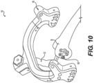
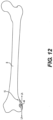
- FIGS. 10-12 show another example bone plate 15 that may be used in the system 10 for treating a fracture in the bone B.
- the bone plate 15 may be oriented to extend generally along or parallel to the longitudinal axis LA of the bone B and be positioned on a medial and/or lateral side of the bone B to engage at least a portion of a condyle and/or shaft of the bone B.
- bone plate 15 has a different shape and/or configuration than that of bone plate 14, bone plate 15 may be used with one or more stabilizing fasteners, intramedullary nail 11, insertion tool 12, and aiming guide 16 in the same or a substantially similar manner.
- the aiming guide 16 may include or define one or more targeting openings 46 extending therethrough that are sized, shaped, and/or configured to receive one or more stabilizing fasteners therethrough.
- the aiming guide 16 is configured to enable a user (e.g., a surgeon) to target or locate one or more nail openings 18 of the intramedullary nail 11 for inserting stabilizing fasteners without fluoroscopy.
- the targeting openings 46 may be arranged or spaced about the aiming guide 16 to form an opening pattern that enables the stabilizing fasteners to be arranged or positioned in one or more desired stabilizing fastener patterns.
- the stabilizing fasteners may be extended through the targeting openings 46, for example, to be in a stabilizing fastener pattern that immobilizes one or more fracture fragments, stabilizes the bone B, and/or otherwise treats a bone fracture.
- one or more targeting openings 46 may be used for plate-nail targeting, washer-nail targeting, and/or blocking screw insertion.
- blocking screws may be extended through one or more targeting openings 46 to guide the trajectory of stabilizing fasteners to gain an anatomic reduction prior to final fixation.
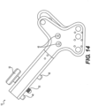
- the aiming guide 16 may include a body and a pair of legs extending from the body. As shown in FIGS. 1 , 9 , 13 , and 15 , the aiming guide 16 may have or include a wishbone-shaped configuration. Each leg may include one or more targeting openings 46 such that targeting openings 46 may be positioned on opposite sides of the bone B, such as medial and lateral sides. In some examples, the aiming guide 16 may be fabricated from one or more composite, radiolucent material. In this manner, the aiming guide 16 will not obstruct the view of the intramedullary nail 11 and/or bone B when using fluoroscopy due to its wishbone-shaped configuration and/or radiolucent material.
- the body of the aiming guide 16 may include one or more locating pins 48 and/or a threaded knob 50 that enables the aiming guide 16 to be desirably positioned and/or oriented relative to insertion tool 12.
- the locating pins 48 are sized, shaped, and/or configured to be received in one or more locating pin openings 52 (shown in FIGS. 3 and 4 ) defined in an upper portion of the handle 20, and/or the threaded knob 50 is sized, shaped, and/or configured to be received in a threaded insert 54 (shown in FIGS. 3 and 4 ) defined in the upper portion of the handle 20.
- the threaded knob 50 may be used to securely couple the aiming guide 16 to the insertion tool 12. Additionally, or alternatively, the insertion tool 12 may include one or more locating pins 48 and/or the threaded knob 50, and/or the aiming guide 16 may include the one or more locating pin openings 52 and/or threaded insert 54 defined therein.
- one or more driver sleeves 56 may be extended through the targeting openings 46 for aligning and/or orienting the stabilizing fasteners.
- the aiming guide 16 may include or define one or more retention mechanisms 58 configured to retain one or more driver sleeves 56 in the targeting openings 46.
- the retention mechanism 58 may include, for example, a peak rod configured to control a movement of the driver sleeves 56.
- the peak rod may extend at least partially across the targeting opening 46 of the aiming guide 16 and may use deflection, due to material properties of the peak rod, to control movement of the one or more stabilizing fasteners.
- the retention mechanism 58 of the aiming guide 16 includes a spring retention system that prevents a driver sleeve 56 from moving or falling out of the targeting openings 46.
- the spring retention system may include at least one spring configured to retain the driver sleeves 56.
- the springs may be retained in a pocket that is off center relative to the targeting opening 46 and may be configured to deflect when a driver sleeve 56 is inserted into the targeting openings 46 and exert a retaining force on an outer diameter of the driver sleeve 56 to prevent the driver sleeve 56 from falling out or slipping out of position.
- the spring deflects and applies a retaining force to the outside of the driver sleeve 56 to prevent movement.
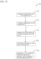
- a method 110 for treating a fracture in a bone B includes coupling an intramedullary nail 11 to an insertion tool 12 at operation 112.
- the intramedullary nail 11 includes one or more nail openings 18 extending therethrough for receiving one or more stabilizing fasteners.
- An aiming guide 16 is coupled to the insertion tool at operation 114.
- the aiming guide 16 includes one or more targeting openings 46 for receiving the stabilizing fasteners.
- the intramedullary nail 11 is implanted within a medullary canal of the bone B at operation 116.
- the aiming guide 16 coupled to the insertion tool 12, the aiming guide 16 is positioned and/or oriented such that the trajectory of one or more targeting openings 46 substantially matches or are coaxial with one or more nail openings 18 of the intramedullary nail 11.
- a bone plate (e.g., bone plate 14, bone plate 15) is positioned at operation 118.
- the bone plate includes one or more plate openings 44 extending therethrough.
- the bone plate may be positioned such that the plate openings 44 are axially aligned with the targeting openings 46. By positioning the bone plate in this manner, the trajectory of the plate openings 44 substantially match or are coaxial with one or more nail openings 18.
- One or more stabilizing fasteners are extended through the plate openings 44 and nail openings 18 using the targeting openings 46 at operation 120.
- the insertion tool 12 facilitates positioning the intramedullary nail 11 to aid in securing the bone B while the stabilizing fasteners are being guided into the plate openings 44 and/or nail openings 18.
- the stabilizing fasteners may be used to interlock the intramedullary nail 11 and bone plate to compress the condyle of the bone B. In this manner, at least some of the load may be distributed along the bone plate instead of being concentrated at the bone B and/or intramedullary nail 11, mitigating trauma to the bone and/or decreasing recovery time.
- Examples described herein may be used to treat one or more bone fractures.
- a user e.g., a surgeon
- a bone plate may be positioned by aligning the plate openings of the bone plate with the targeting openings of the aiming guide.
- the user may extend one or more stabilizing fasteners through the targeting openings of the aiming guide to extend the stabilizing fasteners through the plate openings of the bone plate and the nail openings of the intramedullary nail with the naked eye (e.g., without fluoroscopy).
Landscapes
- Health & Medical Sciences (AREA)
- Orthopedic Medicine & Surgery (AREA)
- Surgery (AREA)
- Life Sciences & Earth Sciences (AREA)
- Heart & Thoracic Surgery (AREA)
- Veterinary Medicine (AREA)
- Engineering & Computer Science (AREA)
- Biomedical Technology (AREA)
- Nuclear Medicine, Radiotherapy & Molecular Imaging (AREA)
- Medical Informatics (AREA)
- Molecular Biology (AREA)
- Animal Behavior & Ethology (AREA)
- General Health & Medical Sciences (AREA)
- Public Health (AREA)
- Neurology (AREA)
- Dentistry (AREA)
- Oral & Maxillofacial Surgery (AREA)
- Surgical Instruments (AREA)
Abstract
An intramedullary nail includes one or more nail openings extending therethrough. The intramedullary nail is implantable within a medullary canal of the bone. A bone plate is configured to engage an outer surface of the bone. The bone plate includes one or more plate openings extending therethrough. The plate openings are spaced about the bone plate such that the bone plate is positionable to axially align the plate openings with the nail openings when the intramedullary nail is implanted within the medullary canal of the bone. An aiming guide includes one or more targeting openings. The targeting openings are spaced about the aiming guide such that the aiming guide is positionable to axially align the targeting openings with the plate openings and the nail openings for extending one or more stabilizing fasteners therethrough when the intramedullary nail is implanted within the medullary canal of the bone.
Description
- The present disclosure generally relates to treating bone fractures.
- Following an injury to a long bone, such as a fracture of the femur or tibia, one or more fixation devices may be used to immobilize the fracture fragments and stabilize the long bone. Intramedullary nails, for example, may be inserted into the intramedullary canal of the bone and provide the appropriate proximal and/or distal fixation. However, known intramedullary devices may suffer from a number of disadvantages. For example, they may be susceptible to implant failure and difficulty in alignment of a fixation screw with respect to the intramedullary nail.
- The present disclosure enables a fixation screw to be extended at least partially through an intramedullary nail. In one aspect, a system is provided for treating a fracture in a bone. The system includes an intramedullary nail including one or more nail openings extending therethrough for receiving one or more stabilizing fasteners. The intramedullary nail is implantable within a medullary canal of the bone. A bone plate is configured to engage an outer surface of the bone. The bone plate includes one or more plate openings extending therethrough for receiving the stabilizing fasteners. The plate openings are spaced about the bone plate such that the bone plate is positionable to axially align the plate openings with the nail openings when the intramedullary nail is implanted within the medullary canal of the bone. An aiming guide includes one or more targeting openings for receiving the stabilizing fasteners. The targeting openings are spaced about the aiming guide such that the aiming guide is positionable to axially align the targeting openings with the plate openings and the nail openings for extending the stabilizing fasteners therethrough when the intramedullary nail is implanted within the medullary canal of the bone.
- In another aspect, an aiming guide is provided for treating a fracture in a bone. The aiming guide includes a body and a pair of legs extending from the body. Each leg of the pair of legs includes one or more targeting openings for receiving one or more stabilizing fasteners therethrough. The targeting openings are spaced about the pair of legs such that the aiming guide is positionable to axially align the targeting openings with one or more openings of an intramedullary nail implanted within a medullary canal of the bone.
- In yet another aspect, a method is provided for treating a fracture in a bone. The method includes coupling an intramedullary nail to an insertion tool. The intramedullary nail includes one or more nail openings extending therethrough for receiving one or more stabilizing fasteners. An aiming guide is coupled to the insertion tool. The aiming guide includes one or more targeting openings for receiving the stabilizing fasteners. The intramedullary nail is implanted within a medullary canal of the bone. A bone plate includes one or more plate openings extending therethrough such that the plate openings are axially aligned with the targeting openings. The stabilizing fasteners are extended through the plate openings and the nail openings using the targeting openings.
-
-
FIG. 1 is a perspective view of an example system for treating a bone fracture, including the insertion tool, an aiming guide, and a bone plate. -
FIG. 2 is a perspective view of an example insertion tool for treating a bone fracture, including a handle and an intramedullary nail coupled to the handle; -
FIG. 3 is a perspective view of the insertion tool shown inFIG. 2 ; -
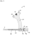
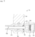
FIGS. 4 and5 are detailed cross-sectional views of the insertion tool shown inFIG. 2 with an example assembly shaft; -
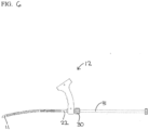
FIG. 6 is a side view of the insertion tool shown inFIG. 2 with an example backslap shaft; -
FIG. 7 is a side view of the bone plate shown inFIG. 1 coupled to a long bone; -
FIG. 8 is a top view of the bone plate shown inFIG. 1 coupled to the long bone; -
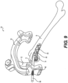
FIG. 9 is a perspective views of the system shown inFIG. 1 including driver sleeves; -
FIG. 10 is a perspective view of another example system for treating a bone fracture, including the insertion tool, the aiming guide, and another bone plate; -
FIG. 11 is a side view of the bone plate shown inFIG. 10 coupled to a long bone; -
FIG. 12 is a top view of the bone plate shown inFIG. 10 coupled to the long bone; -
FIG. 13 is an alternative perspective views of the system shown inFIG. 6 including driver sleeves; -
FIG. 14 is a side view of the aiming guide shown inFIG. 1 ; -
FIG. 15 is a front view of the aiming guide shown inFIG. 1 ; -
FIG. 16 is a cross-sectional view taken along line A-A inFIG. 15 ; -
FIG. 17 is a detailed view of circle A inFIG. 16 ; and -
FIG. 18 is a flowchart of an example method for treating bone fractures. - Corresponding reference characters indicate corresponding parts throughout the drawings.
-
FIG. 1 shows asystem 10 for treating a fracture in a bone B. Thesystem 10 may include theintramedullary nail 11 andinsertion tool 12, a bone plate 14 (e.g., a washer plate), and/or an aimingguide 16. Referring toFIGS. 2-6 , anexample insertion tool 12 may be coupled to anintramedullary nail 11 for use in handling or moving theintramedullary nail 11. Theinsertion tool 12 may be used, for example, to advance, retract, and/or rotate theintramedullary nail 11. In some examples, theinsertion tool 12 is used to insert theintramedullary nail 11 into a long bone (e.g., after reaming). - The
intramedullary nail 11 includes an elongate body extending between a distal end and a proximal end. In some examples, theintramedullary nail 11 defines a hollow channel extending axially therethrough. Alternatively, theintramedullary nail 11 may be solid along its length. Theintramedullary nail 11 is configured to extend axially within the intramedullary canal of a bone. In some examples, theintramedullary nail 11 may be substantially straight. Alternatively, theintramedullary nail 11 may include one or more curves or bends that conform to the anatomical shape of the intramedullary canal. - The
intramedullary nail 11 may be comprised of one or more biocompatible materials that enable the intramedullary nail to have sufficient strength to secure and hold bone. For example, theintramedullary nail 11 includes one or more of titanium, cobalt chrome, cobalt-chrome-molybdenum, stainless steel, tungsten carbide, carbon composite, polyetheretherketone (PEEK), polyethylene, ultra-high molecular weight polyethylene (UHMWPE), resorbable polylactic acid (PLA), polyglycolic acid (PGA), and/or an alloy of such materials. - As shown in
FIG. 2 , theintramedullary nail 11 may include one or more slots and/ornail openings 18 extending therethrough. Thenail openings 18 are arranged or spaced to form an opening pattern about theintramedullary nail 11. Thenail openings 18 may be configured to receive and guide one or more stabilizing fasteners (e.g., nail, screw, bolt) therethrough. In some examples, one ormore nail openings 18 may include one or more threads configured to engage one or more threads of the stabilizing fasteners. Each nail opening 18 may be oriented to have a trajectory defining an angle relative to the longitudinal axis of theintramedullary nail 11. For example, thenail openings 18 may be defined to extend generally radially in the anterior-posterior (AP) and/or medio-lateral (ML) direction. Alternatively, thenail openings 18 may be oriented to have any trajectory that enables theintramedullary nail 11 to function as described herein. - The
insertion tool 12 includes ahandle 20 and aninsertion shaft 22 extending from thehandle 20 in a distal direction. Theinsertion shaft 22 may include one ormore orientation tabs 24 that enable theintramedullary nail 11 to be desirably positioned and/or oriented relative toinsertion tool 12. As shown in the current example, theinsertion shaft 22 has threeorientation tabs 24 distally extending from its distal end that aid in ensuring that theintramedullary nail 11 is oriented correctly when the intramedullary nail is coupled to the insertion shaft. For example, theintramedullary nail 11 may be oriented such that thenail openings 18 extend generally radially in the AP and/or ML direction. In some examples, theinsertion shaft 22 may include one ormore grooves 26 at a distal portion thereof to enable a user (e.g., surgeon) to locate a proximal end of the intramedullary nail 11 (e.g., under fluoroscopy). Thegrooves 26 may be spaced axially about 0.2 inches (about 5.0 millimeters) apart and/or extend circumferentially about an outer surface of theinsertion shaft 22. - As shown in
FIGS. 4 and5 , theinsertion shaft 22 may extend at least partially through thehandle 20 and/or include a flange at a proximal portion thereof that seats into a groove defined in a proximal surface of thehandle 20. In some examples, thehandle 20 is fabricated from a composite material, and/or theinsertion shaft 22 is fabricated from a stainless steel material. Alternatively, thehandle 20 and/orinsertion shaft 22 may be fabricated from any combination of materials that enables theinsertion tool 12 to function as described herein. - As shown in
FIGS. 4 and5 , theinsertion shaft 22 may define a cannula orchannel 28 extending axially therethrough. Aconnection bolt 30 may be extended axially through thechannel 28 of theinsertion shaft 22 to facilitate quick and easy assembly of theintramedullary nail 11 onto theinsertion tool 12. For example, theconnection bolt 30 may be translated axially to selectively extend a distal end of theconnection bolt 30 beyond a distal end of theinsertion shaft 22 and into a proximal end of theintramedullary nail 11. When theconnection bolt 30 is translated axially to selectively retract the distal end of theconnection bolt 30, the distal end of theinsertion shaft 22 acts as a stop for theintramedullary nail 11 such that the distal end of theconnection bolt 30 may be withdrawn from the proximal end of theintramedullary nail 11. - The
connection bolt 30 may include one or moreexternal threads 32 configured to engage or cooperate with one or moreinternal threads 34 of theinsertion shaft 22. As shown inFIGS. 4 and5 , when theexternal threads 32 of theconnection bolt 30 are distal to theinternal threads 34 of theinsertion shaft 22 and in a cavity defined by the insertion shaft 22 (i.e., theconnection bolt 30 is fully threaded into the insertion shaft 22), the threads of theconnection bolt 30 and/orinsertion shaft 22 are configured to prevent the external threads of theconnection bolt 30 from falling out of the cavity while allowing the external threads of theconnection bolt 30 to freely translate within the cavity. In this manner, theconnection bolt 30 may be configured to translate axially a predetermined distance. In some examples, a user (e.g., surgeon) may strike a proximal portion of theconnection bolt 30 to impact theintramedullary nail 11 through theinsertion tool 12. - In some examples, an
assembly shaft 36 may be used to further aid in the connection of theintramedullary nail 11 onto theinsertion tool 12. As shown inFIG. 4 , theassembly shaft 36 may be inserted into and through theconnection bolt 30 and/orinsertion shaft 22. A distal end of theassembly shaft 36 may be selectively extended beyond the distal end ofinsertion shaft 22 and/orconnection bolt 30 and into the channel or cannula of theintramedullary nail 11. In this manner, theassembly shaft 36 may be used to align theintramedullary nail 11 with theinsertion shaft 22 and/orconnection bolt 30 as theintramedullary nail 11 is coupled to the insertion tool 12 (e.g., connection bolt 30). Theassembly shaft 36 may include a latchingfeature 38 that interfaces with an undercutgroove 40 in theconnection bolt 30 to retain theassembly shaft 36 once inserted. - As shown in
FIG. 6 , theinsertion tool 12 may include or be coupled to a backslap shaft 41 for use in retracting theintramedullary nail 11. The backslap shaft 41 may be coupled to theinsertion shaft 22 and/orconnection bolt 30. For example, as shown inFIGS. 4 and5 , theconnection bolt 30 may include one or moreinternal threads 43 for use in connecting the backslap shaft 41. In this manner, a user (e.g., surgeon) may strike a proximal portion of the backslap shaft 41 (e.g., in a proximal direction) to impact theintramedullary nail 11 through theinsertion tool 12. - As shown in
FIGS. 7 and8 , thebone plate 14 may be oriented to extend generally along or parallel to a longitudinal axis LA of the bone B and positioned on a medial and/or lateral side of the bone B to engage at least a portion of a condyle and/or shaft of the bone B. In some examples, thebone plate 14 is configured and/or contoured to match or lie substantially parallel to a particular outer bone surface, such as an epiphysis region, a metaphysis region, and/or a diaphysis region of the bone B. In this manner, thebone plate 14 may be used to stabilize distal femur fractures as well as distal femur articular fractures as a stand-alone reduction device, a provisional fixation device, and/or a final fixation device. - In some examples, the
bone plate 14 may be used with one or more stabilizing fasteners (e.g., nail, screw, bolt) to increase a load carrying capability of the construct. For example, thebone plate 14 may be used with standard locking screws and/or with dedicated washer bolts that compress the condyles of the bone B when tightened and/or provide support to the articular block and femoral shaft. In some examples, the stabilizing fasteners may be extended through one ormore nail openings 18 of theintramedullary nail 11. - As shown in
FIGS. 7 and8 , thebone plate 14 may include or define one ormore plate openings 44 extending therethrough that are sized, shaped, and/or configured to receive one or more stabilizing fasteners therethrough. Theplate openings 44 may be arranged or spaced about thebone plate 14 to form an opening pattern that enables the stabilizing fasteners to be arranged or positioned in one or more desired stabilizing fastener patterns. The stabilizing fasteners may be extended through theplate openings 44, for example, to be in a stabilizing fastener pattern that immobilizes one or more fracture fragments, stabilizes the bone B, and/or otherwise treats a bone fracture. In some examples, as shown inFIG. 9 , thebone plate 14 may be positioned and/or oriented such that the trajectory of one ormore plate openings 44 substantially matches or are coaxial with one ormore nail openings 18 of theintramedullary nail 11 so that thebone plate 14 and theintramedullary nail 11 may be interlocked together. Thebone plate 14 may be attached with locking or non-locking screws using either freehand technique or using an aiming guide (e.g., aiming guide 16). -
FIGS. 10-12 show anotherexample bone plate 15 that may be used in thesystem 10 for treating a fracture in the bone B.Like bone plate 14, shown inFIGS. 7-9 , thebone plate 15 may be oriented to extend generally along or parallel to the longitudinal axis LA of the bone B and be positioned on a medial and/or lateral side of the bone B to engage at least a portion of a condyle and/or shaft of the bone B. Whilebone plate 15 has a different shape and/or configuration than that ofbone plate 14,bone plate 15 may be used with one or more stabilizing fasteners,intramedullary nail 11,insertion tool 12, and aimingguide 16 in the same or a substantially similar manner. - Referring to
FIGS. 1 ,9 , and13-14 , the aimingguide 16 may include or define one ormore targeting openings 46 extending therethrough that are sized, shaped, and/or configured to receive one or more stabilizing fasteners therethrough. The aimingguide 16 is configured to enable a user (e.g., a surgeon) to target or locate one ormore nail openings 18 of theintramedullary nail 11 for inserting stabilizing fasteners without fluoroscopy. For example, the targetingopenings 46 may be arranged or spaced about the aimingguide 16 to form an opening pattern that enables the stabilizing fasteners to be arranged or positioned in one or more desired stabilizing fastener patterns. The stabilizing fasteners may be extended through the targetingopenings 46, for example, to be in a stabilizing fastener pattern that immobilizes one or more fracture fragments, stabilizes the bone B, and/or otherwise treats a bone fracture. In some examples, one ormore targeting openings 46 may be used for plate-nail targeting, washer-nail targeting, and/or blocking screw insertion. For example, blocking screws may be extended through one ormore targeting openings 46 to guide the trajectory of stabilizing fasteners to gain an anatomic reduction prior to final fixation. - In some examples, the aiming
guide 16 may include a body and a pair of legs extending from the body. As shown inFIGS. 1 ,9 ,13 , and15 , the aimingguide 16 may have or include a wishbone-shaped configuration. Each leg may include one ormore targeting openings 46 such that targetingopenings 46 may be positioned on opposite sides of the bone B, such as medial and lateral sides. In some examples, the aimingguide 16 may be fabricated from one or more composite, radiolucent material. In this manner, the aimingguide 16 will not obstruct the view of theintramedullary nail 11 and/or bone B when using fluoroscopy due to its wishbone-shaped configuration and/or radiolucent material. - As shown in
FIGS. 14 and15 , the body of the aimingguide 16 may include one or more locating pins 48 and/or a threadedknob 50 that enables the aimingguide 16 to be desirably positioned and/or oriented relative toinsertion tool 12. In some examples, the locating pins 48 are sized, shaped, and/or configured to be received in one or more locating pin openings 52 (shown inFIGS. 3 and4 ) defined in an upper portion of thehandle 20, and/or the threadedknob 50 is sized, shaped, and/or configured to be received in a threaded insert 54 (shown inFIGS. 3 and4 ) defined in the upper portion of thehandle 20. The threadedknob 50 may be used to securely couple the aimingguide 16 to theinsertion tool 12. Additionally, or alternatively, theinsertion tool 12 may include one or more locating pins 48 and/or the threadedknob 50, and/or the aimingguide 16 may include the one or morelocating pin openings 52 and/or threadedinsert 54 defined therein. - In some examples, as shown in
FIGS. 9 and13 , one ormore driver sleeves 56 may be extended through the targetingopenings 46 for aligning and/or orienting the stabilizing fasteners. As shown inFIGS. 16 and17 , the aimingguide 16 may include or define one ormore retention mechanisms 58 configured to retain one ormore driver sleeves 56 in the targetingopenings 46. Theretention mechanism 58 may include, for example, a peak rod configured to control a movement of thedriver sleeves 56. The peak rod may extend at least partially across the targetingopening 46 of the aimingguide 16 and may use deflection, due to material properties of the peak rod, to control movement of the one or more stabilizing fasteners. In some examples, theretention mechanism 58 of the aimingguide 16 includes a spring retention system that prevents adriver sleeve 56 from moving or falling out of the targetingopenings 46. As shown inFIGS. 16 and17 , the spring retention system may include at least one spring configured to retain thedriver sleeves 56. The springs may be retained in a pocket that is off center relative to the targetingopening 46 and may be configured to deflect when adriver sleeve 56 is inserted into the targetingopenings 46 and exert a retaining force on an outer diameter of thedriver sleeve 56 to prevent thedriver sleeve 56 from falling out or slipping out of position. When thedriver sleeve 56 is inserted into the targetingopening 46, the spring deflects and applies a retaining force to the outside of thedriver sleeve 56 to prevent movement. - Referring to
FIG. 18 , a method 110 for treating a fracture in a bone B includes coupling anintramedullary nail 11 to aninsertion tool 12 atoperation 112. Theintramedullary nail 11 includes one ormore nail openings 18 extending therethrough for receiving one or more stabilizing fasteners. - An aiming
guide 16 is coupled to the insertion tool at operation 114. The aimingguide 16 includes one ormore targeting openings 46 for receiving the stabilizing fasteners. - The
intramedullary nail 11 is implanted within a medullary canal of the bone B atoperation 116. With the aimingguide 16 coupled to theinsertion tool 12, the aimingguide 16 is positioned and/or oriented such that the trajectory of one ormore targeting openings 46 substantially matches or are coaxial with one ormore nail openings 18 of theintramedullary nail 11. - A bone plate (e.g.,
bone plate 14, bone plate 15) is positioned atoperation 118. The bone plate includes one ormore plate openings 44 extending therethrough. The bone plate may be positioned such that theplate openings 44 are axially aligned with the targetingopenings 46. By positioning the bone plate in this manner, the trajectory of theplate openings 44 substantially match or are coaxial with one ormore nail openings 18. - One or more stabilizing fasteners are extended through the
plate openings 44 andnail openings 18 using the targetingopenings 46 atoperation 120. Theinsertion tool 12 facilitates positioning theintramedullary nail 11 to aid in securing the bone B while the stabilizing fasteners are being guided into theplate openings 44 and/ornail openings 18. The stabilizing fasteners may be used to interlock theintramedullary nail 11 and bone plate to compress the condyle of the bone B. In this manner, at least some of the load may be distributed along the bone plate instead of being concentrated at the bone B and/orintramedullary nail 11, mitigating trauma to the bone and/or decreasing recovery time. - Examples described herein may be used to treat one or more bone fractures. When an insertion tool is coupled to an aiming guide, a user (e.g., a surgeon) may extend one or more stabilizing fasteners at least partially through an intramedullary nail implanted within a medullary canal of a bone with the naked eye (e.g., without fluoroscopy) by extending the stabilizing fasteners through the targeting openings of the aiming guide. In some examples, a bone plate may be positioned by aligning the plate openings of the bone plate with the targeting openings of the aiming guide. In this manner, the user may extend one or more stabilizing fasteners through the targeting openings of the aiming guide to extend the stabilizing fasteners through the plate openings of the bone plate and the nail openings of the intramedullary nail with the naked eye (e.g., without fluoroscopy).
- When introducing elements of the present disclosure or the one or more embodiment(s) thereof, the articles "a", "an", "the" and "said" are intended to mean that there are one or more of the elements. The terms "comprising", "including" and "having" are intended to be inclusive and mean that there may be additional elements other than the listed elements.
- As various changes could be made in the above apparatuses, systems, and methods without departing from the scope of the invention, it is intended that all matter contained in the above description and shown in the accompanying drawings shall be interpreted as illustrative and not in a limiting sense.
- The invention could be defined inter alia by the following Examples:
- 1. A system for treating a fracture in a bone, the system comprising: an intramedullary nail including one or more nail openings extending therethrough for receiving one or more stabilizing fasteners, the intramedullary nail implantable within a medullary canal of the bone; a bone plate configured to engage an outer surface of the bone, the bone plate including one or more plate openings extending therethrough for receiving the one or more stabilizing fasteners, the one or more plate openings spaced about the bone plate such that the bone plate is positionable to axially align the one or more plate openings with the one or more nail openings when the intramedullary nail is implanted within the medullary canal of the bone; and an aiming guide including one or more targeting openings for receiving the one or more stabilizing fasteners, the one or more targeting openings spaced about the aiming guide such that the aiming guide is positionable to axially align the one or more targeting openings with the one or more plate openings and the one or more nail openings for extending the one or more stabilizing fasteners therethrough when the intramedullary nail is implanted within the medullary canal of the bone.
- 2. The system of Example 1, further comprising an insertion tool coupleable to the intramedullary nail and the aiming guide, wherein the aiming guide is positioned such that the one or more targeting openings are axially aligned with the one or more nail openings when the insertion tool is coupled to the intramedullary nail and the aiming guide.
- 3. The system of Example 2, wherein the insertion tool includes a handle and an insertion shaft extending from the handle, the insertion shaft including one or more orientation tabs at a distal end thereof.
- 4. The system of Example 2, wherein the insertion tool includes a handle and an insertion shaft extending from the handle, the insertion shaft including one or more grooves defined in at a distal portion thereof.
- 5. The system of Example 2, wherein the insertion tool includes a handle and an insertion shaft extending at least partially through the handle, the insertion shaft including a flange at a proximal portion thereof seated in a groove defined in a proximal surface of the handle.
- 6. The system of Example 2, wherein the insertion tool includes a handle, an insertion shaft, and a connection bolt, the connection bolt extending axially through the insertion shaft such that the connection bolt is axially translatable a predetermined distance.
- 7. The system of Example 2, wherein the insertion tool includes a handle, an insertion shaft, and a connection bolt, the connection bolt extending axially through the insertion shaft, the insertion shaft including one or more internal threads, the connection bolt including one or more external threads configured to engage or cooperate with the one or more internal threads of the insertion shaft.
- 8. The system of Example 2, wherein the insertion tool includes a handle, an insertion shaft, and a connection bolt, the connection bolt extending axially through the insertion shaft, the connection bolt including one or more external threads positionable in a cavity defined by the insertion shaft.
- 9. The system of Example 2, wherein the insertion tool includes a handle, an insertion shaft, and an assembly shaft extending axially through the insertion shaft such that a distal end of the assembly shaft extends beyond a distal end of the insertion shaft.
- 10. The system of Example 2, wherein the insertion tool includes a handle, a connection bolt defining an undercut groove, and an assembly shaft including a latching feature that interfaces with the undercut groove in the connection bolt.
- 11. The system of Example 2, wherein the insertion tool includes a handle, a connection bolt including one or more internal threads, and a backslap shaft including one or more external threads configured to engage the one or more internal threads.
- 12. The system of Example 2, wherein the aiming guide includes one or more locating pins and the insertion tool includes one or more locating pin openings defined therein for receiving the one or more locating pins.
- 13. The system of Example 2, wherein the aiming guide includes a threaded knob and the insertion tool includes a threaded insert defined therein for receiving the threaded knob.
- 14. The system of Example 1, wherein the aiming guide has a wishbone-shaped configuration including a first leg and a second leg, a first targeting opening of the one or more targeting openings extending through the first leg, a second targeting opening of the one or more targeting openings extending through the second leg.
- 15. The system of Example 1, wherein the aiming guide includes one or more retention mechanisms configured to control a movement of one or more driver sleeves extended through the one or more targeting openings.
- 16. An aiming guide for treating a fracture in a bone, the aiming guide comprising: a body; and a pair of legs extending from the body, each leg of the pair of legs including one or more targeting openings for receiving one or more stabilizing fasteners therethrough, the one or more targeting openings spaced about the pair of legs such that the aiming guide is positionable to axially align the one or more targeting openings with one or more openings of an intramedullary nail implanted within a medullary canal of the bone.
- 17. The aiming guide of Example 16, wherein the body includes one or more locating pins for use in coupling the aiming guide to an insertion tool.
- 18. The aiming guide of Example 16, wherein the body includes a threaded knob for use in coupling the aiming guide to an insertion tool.
- 19. The aiming guide of Example 16, further comprising one or more retention mechanisms configured to control a movement of one or more driver sleeves extended through the one or more targeting openings.
- 20. A method for treating a fracture in a bone, the method comprising:
coupling an intramedullary nail to an insertion tool, the intramedullary nail including one or more nail openings extending therethrough for receiving one or more stabilizing fasteners; coupling an aiming guide to the insertion tool, the aiming guide including one or more targeting openings for receiving the one or more stabilizing fasteners; implanting the intramedullary nail within a medullary canal of the bone; positioning a bone plate including one or more plate openings extending therethrough such that the one or more plate openings are axially aligned with the one or more targeting openings; and extending the one or more stabilizing fasteners through the one or more plate openings and the one or more nail openings using the one or more targeting openings.
Claims (15)
- A system for treating a fracture in a bone, the system comprising:an intramedullary nail including one or more nail openings extending therethrough for receiving one or more stabilizing fasteners, the intramedullary nail configured to be implanted within a medullary canal of the bone;a bone plate configured to engage an outer surface of the bone, the bone plate including one or more plate openings extending therethrough for receiving the one or more stabilizing fasteners, the one or more plate openings spaced about the bone plate such that the bone plate is positionable to axially align the one or more plate openings with the one or more nail openings when the intramedullary nail is implanted within the medullary canal of the bone; andan aiming guide including one or more targeting openings for receiving the one or more stabilizing fasteners, the one or more targeting openings spaced about the aiming guide such that the aiming guide is positionable to axially align the one or more targeting openings with the one or more plate openings and the one or more nail openings for extending the one or more stabilizing fasteners therethrough when the intramedullary nail is implanted within the medullary canal of the bone.
- The system of claim 1, further comprising an insertion tool coupleable to the intramedullary nail and the aiming guide, wherein the aiming guide is positioned such that the one or more targeting openings are axially aligned with the one or more nail openings when the insertion tool is coupled to the intramedullary nail and the aiming guide.
- The system of claim 2, wherein the insertion tool includes a handle and an insertion shaft extending from the handle, the insertion shaft including one or more orientation tabs at a distal end thereof.
- The system of claim 2 or 3, wherein the insertion tool includes a handle and an insertion shaft extending from the handle, the insertion shaft including one or more grooves defined in at a distal portion thereof.
- The system of any one of claims 2 to 4, wherein the insertion tool includes a handle and an insertion shaft extending at least partially through the handle, the insertion shaft including a flange at a proximal portion thereof seated in a groove defined in a proximal surface of the handle.
- The system of any one of claims 2 to 5, wherein the insertion tool includes a handle, an insertion shaft, and a connection bolt, the connection bolt extending axially through the insertion shaft such that the connection bolt is axially translatable a predetermined distance.
- The system of any one of claims 2 to 6, wherein the insertion tool includes a handle, an insertion shaft, and a connection bolt, the connection bolt extending axially through the insertion shaft, the insertion shaft including one or more internal threads, the connection bolt including one or more external threads configured to engage or cooperate with the one or more internal threads of the insertion shaft.
- The system of any one of claims 2 to 7, wherein the insertion tool includes a handle, an insertion shaft, and a connection bolt, the connection bolt extending axially through the insertion shaft, the connection bolt including one or more external threads positionable in a cavity defined by the insertion shaft.
- The system of any one of claims 2 to 8, wherein the insertion tool includes a handle, an insertion shaft, and an assembly shaft extending axially through the insertion shaft such that a distal end of the assembly shaft extends beyond a distal end of the insertion shaft.
- The system of any one of claims 2 to 9, wherein the insertion tool includes a handle, a connection bolt defining an undercut groove, and an assembly shaft including a latching feature that interfaces with the undercut groove in the connection bolt.
- The system of any one of claims 2 to 10, wherein the insertion tool includes a handle, a connection bolt including one or more internal threads, and a backslap shaft including one or more external threads configured to engage the one or more internal threads.
- The system of any one of claims 2 to 11, wherein the aiming guide includes one or more locating pins and the insertion tool includes one or more locating pin openings defined therein for receiving the one or more locating pins.
- The system of any one of claims 2 to 12, wherein the aiming guide includes a threaded knob and the insertion tool includes a threaded insert defined therein for receiving the threaded knob.
- The system of claim any one of the preceding claims, wherein the aiming guide has a wishbone-shaped configuration including a first leg and a second leg, a first targeting opening of the one or more targeting openings extending through the first leg, a second targeting opening of the one or more targeting openings extending through the second leg.
- The system of any one of the preceding claims, wherein the aiming guide includes one or more retention mechanisms configured to control a movement of one or more driver sleeves extended through the one or more targeting openings.
Applications Claiming Priority (1)
| Application Number | Priority Date | Filing Date | Title |
|---|---|---|---|
| US17/578,745 US12064150B2 (en) | 2022-01-19 | 2022-01-19 | System and method for treating bone fractures |
Publications (1)
| Publication Number | Publication Date |
|---|---|
| EP4215132A1 true EP4215132A1 (en) | 2023-07-26 |
Family
ID=85017849
Family Applications (1)
| Application Number | Title | Priority Date | Filing Date |
|---|---|---|---|
| EP23152403.4A Pending EP4215132A1 (en) | 2022-01-19 | 2023-01-19 | System for treating bone fractures |
Country Status (3)
| Country | Link |
|---|---|
| US (2) | US12064150B2 (en) |
| EP (1) | EP4215132A1 (en) |
| JP (1) | JP7508608B2 (en) |
Cited By (1)
| Publication number | Priority date | Publication date | Assignee | Title |
|---|---|---|---|---|
| WO2026117709A1 (en) * | 2024-11-27 | 2026-06-04 | Arthrex, Inc. | Bone fracture repair kit, components, and methods of use of same |
Families Citing this family (4)
| Publication number | Priority date | Publication date | Assignee | Title |
|---|---|---|---|---|
| ES2710339T3 (en) * | 2012-12-28 | 2019-04-24 | Paragon 28 Inc | Alignment guide system |
| WO2023023161A1 (en) * | 2021-08-17 | 2023-02-23 | Edward Perez | Bone fixation devices, systems, and methods |
| US20250090207A1 (en) * | 2023-09-15 | 2025-03-20 | Globus Medical, Inc. | Targeted plate-nail constructs |
| WO2026122439A1 (en) * | 2024-12-05 | 2026-06-11 | Smith & Nephew, Inc. | Intramedullary nail aiming arm and sleeve retention mechanisms |
Citations (9)
| Publication number | Priority date | Publication date | Assignee | Title |
|---|---|---|---|---|
| US20070083213A1 (en) * | 2005-09-19 | 2007-04-12 | Mark Siravo | Orthopedic implant insertion handle and aiming guide |
| US20070219636A1 (en) * | 2004-04-12 | 2007-09-20 | Thakkar Navin N | implant assembly for proximal femoral fracture |
| US20090240252A1 (en) * | 2008-03-19 | 2009-09-24 | Chia Hsieh Chang | Targeting apparatus connecting to locking nails for the correction and fixation of femur deformity of a child |
| US20160374738A1 (en) * | 2015-06-24 | 2016-12-29 | Interfix, Llc | Combined Intramedullary and Extramedullary Surgical Aiming System And Method |
| US20180125545A1 (en) * | 2014-09-30 | 2018-05-10 | Arthrex, Inc. | Intramedullary fracture fixation devices and methods |
| US20190000509A1 (en) * | 2017-06-30 | 2019-01-03 | DePuy Synthes Products, Inc. | Variable-angle bone plate placement tool, system, and method of using the same |
| US20190314106A1 (en) * | 2016-10-31 | 2019-10-17 | Epix Orthopaedics, Inc. | Method for preparing implantable device for use |
| US20200069318A1 (en) * | 2016-09-22 | 2020-03-05 | Globus Medical, Inc. | Systems and methods for intramedullary nail implantation |
| US20210275195A1 (en) * | 2016-09-30 | 2021-09-09 | Wright Medical Technology, Inc. | Targeting guide and method for an implant |
Family Cites Families (282)
| Publication number | Priority date | Publication date | Assignee | Title |
|---|---|---|---|---|
| US1105105A (en) | 1912-02-10 | 1914-07-28 | William O'n Sherman | Surgical appliance. |
| US2486303A (en) | 1948-04-29 | 1949-10-25 | Harry Herschel Leiter | Surgical appliance for bone fractures |
| US3463148A (en) | 1966-01-20 | 1969-08-26 | Richards Mfg Co | Bone plate |
| US3695259A (en) | 1970-11-10 | 1972-10-03 | Clyde E Yost | Bone plate |
| US3716050A (en) | 1971-02-11 | 1973-02-13 | F Johnston | Olecranon plate |
| CH613858A5 (en) | 1977-04-22 | 1979-10-31 | Straumann Inst Ag | |
| CH651192A5 (en) | 1980-11-20 | 1985-09-13 | Synthes Ag | OSTEOSYNTHETIC DEVICE AND CORRESPONDING DRILL GAUGE. |
| FR2517536B1 (en) | 1981-12-09 | 1986-12-12 | Zbikowski Juan | FUNCTIONAL FIXING DEVICE FOR OSTEO-SYNTHESIS USING COMPRESSION PLATES |
| GB2158716B (en) | 1984-05-18 | 1987-09-30 | Technomed Gmk | Bone joining plate |
| US4683878A (en) | 1985-04-29 | 1987-08-04 | Kirschner Medical Corporation | Osteosynthetic fixation plate |
| PL147580B1 (en) | 1986-04-14 | 1989-06-30 | Plate for uniting epiphysis and diaphysis of broken bone | |
| US4776330A (en) | 1986-06-23 | 1988-10-11 | Pfizer Hospital Products Group, Inc. | Modular femoral fixation system |
| US4781183A (en) | 1986-08-27 | 1988-11-01 | American Cyanamid Company | Surgical prosthesis |
| US4966599A (en) | 1987-04-07 | 1990-10-30 | Pollock Richard A | Anatomical precontoured plating, instruments and methods |
| DE8706912U1 (en) | 1987-05-14 | 1987-08-27 | Howmedica GmbH, 2314 Schönkirchen | Small bone plate and screws, particularly for the treatment of fractures of the skull and facial skeleton or similar. |
| US5151103A (en) | 1987-11-03 | 1992-09-29 | Synthes (U.S.A.) | Point contact bone compression plate |
| CH673762A5 (en) | 1987-12-02 | 1990-04-12 | Synthes Ag | |
| US4923471A (en) | 1989-10-17 | 1990-05-08 | Timesh, Inc. | Bone fracture reduction and fixation devices with identity tags |
| IT1237496B (en) | 1989-10-26 | 1993-06-08 | Giuseppe Vrespa | SCREW DEVICE FOR ANCHORING BONE PROSTHESES, METHOD FOR THE APPLICATION OF SUCH DEVICE AND RELATED EQUIPMENT |
| DE9114118U1 (en) | 1991-11-13 | 1992-01-02 | Howmedica GmbH, 2314 Schönkirchen | Supports for the human spine |
| US5779706A (en) | 1992-06-15 | 1998-07-14 | Medicon Eg | Surgical system |
| US6001099A (en) | 1998-06-08 | 1999-12-14 | Huebner; Randall J. | Bone plate with varying rigidity |
| US5364399A (en) | 1993-02-05 | 1994-11-15 | Danek Medical, Inc. | Anterior cervical plating system |
| US5423826A (en) | 1993-02-05 | 1995-06-13 | Danek Medical, Inc. | Anterior cervical plate holder/drill guide and method of use |
| USD365634S (en) | 1993-09-23 | 1995-12-26 | Timesh, Inc. | Metallic surgical grid material |
| US5468242A (en) | 1993-11-19 | 1995-11-21 | Leibinger Gmbh | Form-fitting mesh implant |
| US5578036A (en) | 1993-12-06 | 1996-11-26 | Stone; Kevin T. | Method and apparatus for fixation of bone during surgical procedures |
| US5709687A (en) | 1994-03-16 | 1998-01-20 | Pennig; Dietmar | Fixation pin for small-bone fragments |
| US5601553A (en) | 1994-10-03 | 1997-02-11 | Synthes (U.S.A.) | Locking plate and bone screw |
| US5489305A (en) | 1994-10-03 | 1996-02-06 | Timesh, Inc. | Mandibular prostheses |
| IT1271079B (en) | 1994-11-22 | 1997-05-26 | Lucio Martinotti | RETINA FOR ORTHOPEDIC-TRAUMATOLOGICAL SURGERY |
| SE505453C2 (en) | 1995-02-14 | 1997-09-01 | Robert J Medoff | Implantable support plate |
| JP3542133B2 (en) | 1995-03-27 | 2004-07-14 | ジンテーズ アクチエンゲゼルシャフト,クール | Bone plate |
| KR100424088B1 (en) | 1995-09-06 | 2004-08-04 | 신테스 아게 츄어 | Bone Plate |
| US5676667A (en) | 1995-12-08 | 1997-10-14 | Hausman; Michael | Bone fixation apparatus and method |
| DE29520312U1 (en) | 1995-12-21 | 1996-02-08 | Leibinger Medizintech | Bone screw |
| DE19549180A1 (en) | 1995-12-30 | 1997-07-03 | Bosch Gmbh Robert | Stator for electrical machine |
| US5785712A (en) | 1996-04-16 | 1998-07-28 | Terray Corporation | Reconstruction bone plate |
| US5814048A (en) | 1996-05-03 | 1998-09-29 | Sofamor Danek Properties, Inc. | Cranioplasty plates and method of installation |
| WO1997047251A1 (en) | 1996-06-14 | 1997-12-18 | Depuy Ace Medical Company | Upper extremity bone plate |
| CA2179864C (en) | 1996-06-25 | 2002-05-07 | Robert John Runciman | Bone plate template |
| US5718705A (en) | 1996-07-16 | 1998-02-17 | Sammarco; Giacomo J. | Internal fixation plate |
| EP0917450A1 (en) | 1996-08-12 | 1999-05-26 | SYNTHES AG Chur | Bone plate |
| US5766176A (en) | 1996-09-11 | 1998-06-16 | Walter Lorenz Surgical, Inc. | Formable mesh |
| US5690631A (en) | 1996-09-11 | 1997-11-25 | Walter Lorenz Surgical, Inc. | Multi-configurable plating system |
| US5980540A (en) | 1997-04-11 | 1999-11-09 | Kinamed, Inc. | Perforated cover for covering spaces in the cranium and conforming to the shape of the cranium |
| US5961519A (en) | 1997-04-11 | 1999-10-05 | Kinamed, Inc. | Burr hole cover for cranial surgery |
| ZA983955B (en) | 1997-05-15 | 2001-08-13 | Sdgi Holdings Inc | Anterior cervical plating system. |
| DE19746396A1 (en) | 1997-10-21 | 1999-05-06 | Howmedica Leibinger Gmbh & Co | Grid for the fixation of bone parts or for bridging bone defects |
| US5925048A (en) | 1998-03-13 | 1999-07-20 | Osteomed | Bone screw |
| US5938664A (en) | 1998-03-31 | 1999-08-17 | Zimmer, Inc. | Orthopaedic bone plate |
| US6533786B1 (en) | 1999-10-13 | 2003-03-18 | Sdgi Holdings, Inc. | Anterior cervical plating system |
| DE19858889B4 (en) | 1998-12-19 | 2008-08-07 | Wolter, Dietmar, Prof. Dr.Med. | Fixation system for bones |
| US6093201A (en) | 1999-01-19 | 2000-07-25 | Ethicon, Inc. | Biocompatible absorbable polymer plating system for tissue fixation |
| HK1039267B (en) | 1999-03-09 | 2004-12-31 | Synthes Gmbh | Bone plate |
| JP2002542875A (en) | 1999-05-03 | 2002-12-17 | メダルティス・アクチェンゲゼルシャフト | Bone plate that can be blocked |
| US7094239B1 (en) | 1999-05-05 | 2006-08-22 | Sdgi Holdings, Inc. | Screws of cortical bone and method of manufacture thereof |
| WO2001019267A1 (en) | 1999-09-13 | 2001-03-22 | Synthes Ag Chur | Bone plate system |
| EP1211993B1 (en) | 1999-09-14 | 2005-10-26 | Dietmar Prof. Dr. Wolter | Fixation system for bones |
| AU775910B2 (en) | 2000-01-27 | 2004-08-19 | Synthes Gmbh | Bone plate |
| US6866665B2 (en) | 2003-03-27 | 2005-03-15 | Hand Innovations, Llc | Bone fracture fixation system with subchondral and articular surface support |
| US6358250B1 (en) | 2000-02-01 | 2002-03-19 | Hand Innovations, Inc. | Volar fixation system |
| US7857838B2 (en) | 2003-03-27 | 2010-12-28 | Depuy Products, Inc. | Anatomical distal radius fracture fixation plate |
| US6712820B2 (en) | 2000-02-01 | 2004-03-30 | Hand Innovations, Inc. | Fixation plate system for dorsal wrist fracture fixation |
| US20040153073A1 (en) | 2000-02-01 | 2004-08-05 | Hand Innovations, Inc. | Orthopedic fixation system including plate element with threaded holes having divergent axes |
| US6283969B1 (en) | 2000-03-10 | 2001-09-04 | Wright Medical Technology, Inc. | Bone plating system |
| US6740088B1 (en) | 2000-10-25 | 2004-05-25 | Sdgi Holdings, Inc. | Anterior lumbar plate and method |
| US20070173840A1 (en) | 2006-01-11 | 2007-07-26 | Huebner Randall J | Bone plate with cover |
| US7153309B2 (en) | 2002-11-19 | 2006-12-26 | Acumed Llc | Guide system for bone-repair devices |
| US8518090B2 (en) | 2010-10-05 | 2013-08-27 | Acumed Llc | Fastener with serrated thread for attachment to a bone plate at a selectable angle |
| EP1389963B1 (en) | 2001-05-28 | 2006-06-14 | Synthes AG Chur | Bone plate for the fixation of fractures of the proximal humerus |
| USD458683S1 (en) | 2001-11-13 | 2002-06-11 | Zimmer, Inc. | Orthopaedic bone plate |
| USD458684S1 (en) | 2001-11-13 | 2002-06-11 | Zimmer, Inc. | Orthopaedic bone plate |
| JP2003210478A (en) | 2002-01-18 | 2003-07-29 | Ai-Medic:Kk | Plate for ulnar proximal crush fracture fixation |
| US7322983B2 (en) | 2002-02-12 | 2008-01-29 | Ebi, L.P. | Self-locking bone screw and implant |
| US7862597B2 (en) | 2002-08-22 | 2011-01-04 | Warsaw Orthopedic, Inc. | System for stabilizing a portion of the spine |
| US7179260B2 (en) | 2003-09-29 | 2007-02-20 | Smith & Nephew, Inc. | Bone plates and bone plate assemblies |
| FR2845588B1 (en) | 2002-10-09 | 2006-12-15 | Biotech Internat | SELF-LOCKING OSTEOSYNTHESIS DEVICE |
| US6955677B2 (en) | 2002-10-15 | 2005-10-18 | The University Of North Carolina At Chapel Hill | Multi-angular fastening apparatus and method for surgical bone screw/plate systems |
| USD479331S1 (en) | 2002-11-05 | 2003-09-02 | Zimmer | Orthopedic bone plate |
| FR2846870B1 (en) | 2002-11-07 | 2005-07-01 | Fixano | OSTEOSYNTHESIS EQUIPMENT FOR THE TREATMENT OF A "LONG" CUBITUS |
| US20040097937A1 (en) | 2002-11-19 | 2004-05-20 | Sandi Pike | Orthopedic bone plate |
| KR101081269B1 (en) | 2002-11-19 | 2011-11-08 | 어큠드 엘엘씨 | Adjustable pattern plate |
| US20050187551A1 (en) | 2002-12-02 | 2005-08-25 | Orbay Jorge L. | Bone plate system with bone screws fixed by secondary compression |
| WO2004084701A2 (en) | 2003-03-26 | 2004-10-07 | Swiss Orthopedic Solutions Sa | Locking bone plate |
| US7722653B2 (en) | 2003-03-26 | 2010-05-25 | Greatbatch Medical S.A. | Locking bone plate |
| US7250053B2 (en) | 2003-03-27 | 2007-07-31 | Depuy Products, Inc. | Low profile distal radius fracture fixation plate |
| US7294130B2 (en) | 2003-03-27 | 2007-11-13 | Depuy Products, Inc. | Distal radius fracture fixation plate having K-wire hole structured to fix a K-wire in one dimension relative to the plate |
| US7635381B2 (en) | 2003-03-27 | 2009-12-22 | Depuy Products, Inc. | Anatomical distal radius fracture fixation plate with fixed-angle K-wire holes defining a three-dimensional surface |
| CN100586401C (en) | 2003-04-16 | 2010-02-03 | 波雷克斯外科手术用品公司 | Craniofacial implant |
| US7776076B2 (en) | 2004-05-11 | 2010-08-17 | Synthes Usa, Llc | Bone plate |
| US20050131413A1 (en) | 2003-06-20 | 2005-06-16 | O'driscoll Shawn W. | Bone plate with interference fit screw |
| US8540755B2 (en) | 2003-07-21 | 2013-09-24 | Robin C. Whitmore | Self-drilling self-tapping bone screw |
| US8105367B2 (en) | 2003-09-29 | 2012-01-31 | Smith & Nephew, Inc. | Bone plate and bone plate assemblies including polyaxial fasteners |
| EP1677693B1 (en) | 2003-10-30 | 2009-04-15 | Synthes GmbH | Bone plate |
| CA2544742A1 (en) | 2003-11-05 | 2005-05-19 | Koenigsee Implantate Und Instrumente Zur Osteosynthese Gmbh | Plate used to stabilise distal radius fractures |
| CA2546050C (en) | 2003-11-18 | 2012-08-28 | Synthes Gmbh | Osteosynthesis plate set |
| PL212983B1 (en) | 2003-12-22 | 2012-12-31 | Synthes Gmbh | Bone plate |
| US7637928B2 (en) | 2004-01-26 | 2009-12-29 | Synthes Usa, Llc | Variable angle locked bone fixation system |
| US8574268B2 (en) | 2004-01-26 | 2013-11-05 | DePuy Synthes Product, LLC | Highly-versatile variable-angle bone plate system |
| US7632277B2 (en) | 2004-03-29 | 2009-12-15 | Woll Bioorthopedics Llc | Orthopedic intramedullary fixation system |
| US7717946B2 (en) | 2004-06-07 | 2010-05-18 | Degima Gmbh | Polymeric plate bendable without thermal energy and methods of manufacture |
| US7137987B2 (en) | 2004-07-02 | 2006-11-21 | Wright Medical Technology, Inc. | Distal radius bone plating system with locking and non-locking screws |
| WO2006029274A1 (en) | 2004-09-07 | 2006-03-16 | Smith & Nephew, Inc. | Minimal thickness bone plate locking mechanism |
| US20060173458A1 (en) | 2004-10-07 | 2006-08-03 | Micah Forstein | Bone fracture fixation system |
| US8043297B2 (en) | 2004-11-03 | 2011-10-25 | Synthes Usa, Llc | Aiming arm for bone plates |
| US8394130B2 (en) | 2005-03-17 | 2013-03-12 | Biomet C.V. | Modular fracture fixation system |
| US7604657B2 (en) | 2005-09-19 | 2009-10-20 | Depuy Products, Inc. | Bone fixation plate with complex suture anchor locations |
| US8062296B2 (en) | 2005-03-17 | 2011-11-22 | Depuy Products, Inc. | Modular fracture fixation plate system with multiple metaphyseal and diaphyseal plates |
| US8172886B2 (en) | 2004-12-14 | 2012-05-08 | Depuy Products, Inc. | Bone plate with pre-assembled drill guide tips |
| US8118846B2 (en) | 2005-01-28 | 2012-02-21 | Orthohelix Surgical Designs, Inc. | Orthopedic plates for use in clavicle repair and methods for their use |
| US8118848B2 (en) | 2005-01-28 | 2012-02-21 | Orthohelix Surgical Designs, Inc. | Orthopedic plate for use in fibula repair |
| US7771457B2 (en) | 2005-01-28 | 2010-08-10 | Orthohelix Surgical Designs, Inc. | Orthopedic plate for use in small bone repair |
| EP1693013A1 (en) | 2005-02-22 | 2006-08-23 | Kyon | Plate and screws for treatment of bone fractures |
| US20060241607A1 (en) | 2005-03-31 | 2006-10-26 | Mark Myerson | Metatarsal fixation plate |
| US7344538B2 (en) | 2005-03-31 | 2008-03-18 | Depuy Products, Inc. | Mid-foot fixation plate |
| CN101272743B (en) | 2005-07-25 | 2011-01-26 | 史密夫和内修有限公司 | Polyaxial fastener systems |
| US8382807B2 (en) | 2005-07-25 | 2013-02-26 | Smith & Nephew, Inc. | Systems and methods for using polyaxial plates |
| US8177820B2 (en) | 2005-09-01 | 2012-05-15 | Merete Medical Gmbh | Bone plate comprising at least one screw to be fixed at a stable angle |
| CN102172332A (en) | 2005-10-25 | 2011-09-07 | 圣歌整形外科有限责任公司 | Bone fastening assembly and bushing and screw for use therewith |
| DE502005002257D1 (en) | 2005-12-23 | 2008-01-24 | Aap Implantate Ag | bone plate |
| US8491593B2 (en) | 2006-01-17 | 2013-07-23 | Stryker Trauma Gmbh | Targeting device for orthopedic implants |
| US7473255B2 (en) | 2006-02-08 | 2009-01-06 | Synthes (U.S.A.) | Transbuccal plate holding cannula |
| US8523921B2 (en) | 2006-02-24 | 2013-09-03 | DePuy Synthes Products, LLC | Tibial plateau leveling osteotomy plate |
| US9687282B2 (en) | 2006-03-07 | 2017-06-27 | Orthohelix Surgical Designs, Inc. | Orthopedic plate having threaded holes for locking screws or pegs and non-threaded holes for a variable axis locking mechanism |
| US7875062B2 (en) | 2006-03-07 | 2011-01-25 | Warsaw Orthopedic, Inc. | Methods and devices for retaining bone plate anchors |
| US8808334B2 (en) | 2006-03-07 | 2014-08-19 | Orthohelix Surgical Designs, Inc. | Orthopedic plate |
| US7867261B2 (en) | 2006-03-17 | 2011-01-11 | Depuy Products, Inc. | Bone plate with variable torsional stiffness at fixed angle holes |
| BRPI0601069B1 (en) | 2006-03-17 | 2014-10-14 | Gm Dos Reis Ind E Com Ltda | BONE BOARD |
| US7951178B2 (en) | 2006-04-03 | 2011-05-31 | Acumed Llc | Bone plates with hybrid apertures |
| US8926675B2 (en) | 2006-04-11 | 2015-01-06 | Biomet Manufacturing, Llc | Contoured bone plate |
| US20070270849A1 (en) | 2006-04-21 | 2007-11-22 | Orbay Jorge L | Fixation Plate With Multifunctional Holes |
| US20070288022A1 (en) | 2006-04-25 | 2007-12-13 | Stryker Trauma Gmbh | Bone reconstruction plate with improved fatigue resistance |
| WO2008007194A2 (en) | 2006-07-07 | 2008-01-17 | Precimed, S.A. | Bone plate with complex, adjacent holes joined by a bend relief zone |
| BRPI0713865A2 (en) | 2006-07-07 | 2012-12-11 | Precimed Sa | bone plate, method to install it, and orthopedic kit |
| US8057520B2 (en) | 2006-07-18 | 2011-11-15 | Orthohelix Surgical Designs, Inc. | Calcaneal plate |
| US8267972B1 (en) | 2006-12-01 | 2012-09-18 | Gehlert Rick J | Bone plate |
| US20080234749A1 (en) | 2007-01-26 | 2008-09-25 | Zimmer Technology, Inc. | Bone plate providing threaded locking head screw capture |
| US8870931B2 (en) | 2007-03-21 | 2014-10-28 | The University Of North Carolina At Chapel Hill | Anti-unscrewing and multi-angular fastening apparatuses and methods for surgical bone screw/plate systems |
| WO2008134264A1 (en) | 2007-04-27 | 2008-11-06 | Synthes Usa, Llc | Implant devices constructed with metallic and polymeric components |
| ES2366053T3 (en) | 2007-05-03 | 2011-10-14 | Medartis Ag | FIXING DEVICE, COMBINATION OF A FIXING DEVICE WITH A LONGITUDINAL ELEMENT, SYSTEM WITH A COMBINATION OF THIS CLASS AS WELL AS AN OSTEOSYNTHESIS KIT. |
| AR061999A1 (en) | 2007-07-18 | 2008-08-10 | Pizzicara Mario Angel | BLOCKED PLATE OF COMBINED HOLES, STABILITY CONTROL AND DOUBLE ANGULATION, FOR UNION OF FRACTURED BONES |
| EP2397089B1 (en) | 2007-11-02 | 2014-08-13 | Biomet C.V. | Elbow fracture fixation system |
| US8317842B2 (en) | 2007-11-30 | 2012-11-27 | Biomet C.V. | Distal tibia plating system |
| US8162950B2 (en) | 2007-12-17 | 2012-04-24 | Stryker Leibinger Gmbh & Co. Kg | Bone plate instrument and method |
| EP2247248A1 (en) | 2008-02-06 | 2010-11-10 | Osteomed L.P. | Subcondylar fracture fixation plate system for tubular bones of the hand |
| US8167918B2 (en) | 2008-02-19 | 2012-05-01 | Orthohelix Surgical Designs, Inc. | Orthopedic plate for use in the MTP joint |
| US8257406B2 (en) | 2008-02-19 | 2012-09-04 | Orthohelix Surgical Designs, Inc. | Orthopedic plate for use on a single ray in the midfoot |
| US8257403B2 (en) | 2008-02-19 | 2012-09-04 | Orthohelix Surgical Designs, Inc. | Orthopedic plate for use in the midfoot |
| FR2928259B1 (en) | 2008-03-07 | 2011-04-22 | D L P Sarl | MATERIAL FOR THE REDUCTION OF A FRACTURE, ESPECIALLY A DISTAL RADIUS FRACTURE |
| US8728126B2 (en) | 2008-03-10 | 2014-05-20 | Dennis L. Steffen | Bone fixation system and method |
| US20090228010A1 (en) | 2008-03-10 | 2009-09-10 | Eduardo Gonzalez-Hernandez | Bone fixation system |
| US20090248084A1 (en) | 2008-03-27 | 2009-10-01 | Beat Hintermann | Systems and methods for performing ankle arthrodesis in a human patient |
| WO2009121144A1 (en) | 2008-04-03 | 2009-10-08 | Austofix Group Limited | Tool jig for bone implant assembly |
| US8177822B2 (en) | 2008-05-05 | 2012-05-15 | Lars G. Tellman | Contoured bone plate for fracture fixation having hook members and drill guide for same |
| US8821508B2 (en) | 2008-05-05 | 2014-09-02 | Trimed, Incorporated | Holder/impactor for contoured bone plate for fracture fixation |
| WO2009148762A2 (en) | 2008-05-09 | 2009-12-10 | Skeletal Dynamics Llc | Formable bone plate, clamping apparatus, osteotomy system and method for reconstructing a bone |
| US8343155B2 (en) | 2008-05-15 | 2013-01-01 | Zimmer, Inc. | Cable button |
| EP2303191A4 (en) | 2008-06-02 | 2012-12-12 | Skeletal Dynamics Llc | HYBRID ORTHOPEDIC IMPLANT |
| US8303600B2 (en) * | 2008-06-30 | 2012-11-06 | Biomet C.V. | Targeting apparatus for use in a medical procedure |
| SE533632C2 (en) | 2008-07-01 | 2010-11-09 | Swemac Innovation Ab | Device for internal fixation of the bone fragments in a bone fracture |
| US9072555B2 (en) | 2008-07-21 | 2015-07-07 | Arthrex, Inc. | Carbon fiber reinforced peek bone plate with titanium fixation screws |
| US8262707B2 (en) | 2008-07-31 | 2012-09-11 | Biomet C.V. | Periarticular bone plate with biplanar offset head member |
| US8257405B2 (en) | 2008-07-31 | 2012-09-04 | Biomet C.V. | Periarticular bone plate with biplanar offset head member |
| US20100057086A1 (en) | 2008-08-29 | 2010-03-04 | Zimmer, Inc. | Anodized locking plate components |
| ES2450991T3 (en) | 2008-09-02 | 2014-03-26 | Stryker Trauma Ag | Bone plate with synchronized thread |
| US8906076B2 (en) | 2008-10-17 | 2014-12-09 | Osteomed Llc | Angulated locking plate and screw |
| US8597334B2 (en) | 2008-10-17 | 2013-12-03 | Osteomed Llc | Angulated locking plate/screw interface |
| DE102008043370A1 (en) | 2008-10-31 | 2010-05-06 | Universität Rostock | Fixation device for bones |
| US8403966B2 (en) | 2008-11-24 | 2013-03-26 | Mbd Medical Llc | Clavicle plate and screws |
| US8444679B2 (en) | 2008-11-24 | 2013-05-21 | Mbd Medical Llc | Clavicle plate and screws |
| US8439918B2 (en) | 2008-12-02 | 2013-05-14 | Suspension Orthopaedic Solutions, Inc. | Ulna fixation |
| USD622853S1 (en) | 2009-02-06 | 2010-08-31 | Osteomed L.P. | Hand bone fracture fixation plate |
| US8777998B2 (en) | 2009-02-23 | 2014-07-15 | Orthopediatrics Corp. | Pediatric long bone support or fixation plate |
| WO2010111205A2 (en) | 2009-03-23 | 2010-09-30 | University Of Maryland, Baltimore | Fracture-specific distal radius plates |
| EP2410929B1 (en) | 2009-03-24 | 2019-06-26 | Stabiliz Orthopedics, LLC | Orthopedic fixation device with bioresorbable layer |
| US9322562B2 (en) | 2009-04-01 | 2016-04-26 | Mitsubishi Electric Corporation | Air-conditioning apparatus |
| DE102009016394B4 (en) | 2009-04-07 | 2016-02-11 | Merete Medical Gmbh | Device for stable-angle fixation and compression of a fracture site or osteotomy on a bone |
| EP2238936B1 (en) | 2009-04-09 | 2012-05-23 | Arthrex, Inc. | Clavicle nail with locking end cap |
| EP2248479B1 (en) | 2009-05-06 | 2012-09-19 | Greatbatch Ltd. | Bone plate assembly |
| US8808333B2 (en) | 2009-07-06 | 2014-08-19 | Zimmer Gmbh | Periprosthetic bone plates |
| US8834532B2 (en) | 2009-07-07 | 2014-09-16 | Zimmer Gmbh | Plate for the treatment of bone fractures |
| US9259255B2 (en) | 2009-07-15 | 2016-02-16 | Orthohelix Surgical Designs, Inc. | Variable axis locking mechanism for use in orthopedic implants |
| EP2482742A1 (en) | 2009-09-30 | 2012-08-08 | Strathmore Industries Inc. | Apparatus and method for a suture button |
| US9510878B2 (en) | 2009-11-16 | 2016-12-06 | The Research Foundation For The State University Of New York | Pre-curved intramedullary clavicle nail and method of using same |
| US9161795B2 (en) | 2009-12-22 | 2015-10-20 | Merete Medical Gmbh | Bone plate system for osteosynthesis |
| US9486262B2 (en) | 2010-01-27 | 2016-11-08 | DePuy Synthes Products, Inc. | System and method for minimally invasive clavicle plate application |
| WO2011109127A1 (en) | 2010-03-04 | 2011-09-09 | Synthes Usa, Llc | Ulna osteotomy system |
| US8764751B2 (en) | 2010-03-04 | 2014-07-01 | Skeletal Dynamics, Llc | Endosteal nail plate for fixing bone segments |
| US20110218580A1 (en) | 2010-03-08 | 2011-09-08 | Stryker Trauma Sa | Bone fixation system with curved profile threads |
| US9113970B2 (en) | 2010-03-10 | 2015-08-25 | Orthohelix Surgical Designs, Inc. | System for achieving selectable fixation in an orthopedic plate |
| US20120059424A1 (en) | 2010-03-10 | 2012-03-08 | Advanced Orthopaedic Solutions, Inc. | Clavicle Bone Plate |
| US8603148B2 (en) | 2010-05-07 | 2013-12-10 | Raymond B. Raven, III | System for treating bone fractures |
| ES2427981T3 (en) | 2010-05-25 | 2013-11-05 | Stryker Trauma Sa | Bone fixation implant |
| USD646785S1 (en) | 2010-05-27 | 2011-10-11 | Ebi, Llc | Orthopedic volar bone plate |
| USD643121S1 (en) | 2010-05-27 | 2011-08-09 | Ebi, Llc | Orthopedic wrist spanning bone plate |
| EP2575656B1 (en) | 2010-06-07 | 2019-04-10 | Carbofix Orthopedics Ltd. | Composite material bone implant |
| DE102010025001B4 (en) | 2010-06-24 | 2016-08-04 | Aap Implantate Ag | Fixation system with bone plate and bone screw |
| US20130138156A1 (en) | 2010-09-02 | 2013-05-30 | Neosteo | Osteosynthesis device |
| CA2810829A1 (en) | 2010-09-09 | 2012-03-15 | Synthes Usa, Llc | Surgical nail |
| GB2486043B (en) | 2010-09-27 | 2012-10-24 | Acumed Llc | Instruments having a radiopaque region to facilitate positioning a bone plate on bone |
| EP2623057B1 (en) | 2010-09-28 | 2024-01-03 | Olympus Terumo Biomaterials Corp. | Bone plate and bone plate system |
| US8523862B2 (en) | 2011-04-04 | 2013-09-03 | Stryker Leibinger Gmbh & Co. Kg | Bone plate aiming block |
| WO2012050572A1 (en) | 2010-10-13 | 2012-04-19 | Stryker Leibinger Gmbh & Co., Kg. | Bone plate aiming block |
| EP2455002B1 (en) | 2010-11-17 | 2019-04-03 | Arthrex, Inc. | Adjustable suture-button construct for ankle syndesmosis repair |
| CN201987653U (en) | 2010-12-22 | 2011-09-28 | 蔡林 | Clavicular hook steel plate |
| US8551095B2 (en) | 2011-02-02 | 2013-10-08 | Bionet Manufacturing, LLC | Bone plate having combination locking and compression screw holes |
| US20120203227A1 (en) | 2011-02-08 | 2012-08-09 | Christopher Harris Martin | Low profile dorsal plate |
| TWI548389B (en) * | 2011-02-14 | 2016-09-11 | 星瑟斯有限公司 | Intramedullary nail having self-retaining compression slot |
| WO2012121830A1 (en) | 2011-03-04 | 2012-09-13 | Synthes Usa, Llc | Modular hook plate assembly |
| US20120232599A1 (en) | 2011-03-10 | 2012-09-13 | Jared Schoenly | Awl screw fixation members and related systems |
| US9427269B2 (en) | 2011-03-14 | 2016-08-30 | Genossis Llc | Locking screws and plates |
| JP6063442B2 (en) | 2011-04-01 | 2017-01-18 | シンセス・ゲーエムベーハーSynthes GmbH | Posterior vertebra plating system |
| WO2012156453A1 (en) | 2011-05-17 | 2012-11-22 | Dietmar Wolter | Bone plate |
| US8728082B2 (en) | 2011-05-26 | 2014-05-20 | Biomet Manufacturing, Llc | Bone plate positioning scaffold |
| JP2014522673A (en) | 2011-06-15 | 2014-09-08 | スミス アンド ネフュー インコーポレーテッド | Locking implant with variable angle |
| US20130018426A1 (en) | 2011-07-11 | 2013-01-17 | Feng-Te Tsai | Bone Plate Module with Adjustable Fixing Direction and an Adjustment Ring Thereof |
| TWM419549U (en) | 2011-08-18 | 2012-01-01 | Univ Nat Yang Ming | Bendable bone plate for external fixation use |
| CN202313691U (en) | 2011-09-01 | 2012-07-11 | 吴荣博 | Proximal ulna hook plate |
| EP2753255B1 (en) | 2011-09-06 | 2016-08-10 | DePuy Synthes Products, LLC | Pancarpal arthrodesis bone plate |
| US10098677B2 (en) | 2011-09-06 | 2018-10-16 | Globus Medical, Inc. | Spinal plate |
| US8551143B2 (en) | 2011-10-11 | 2013-10-08 | Brent Lane Norris | Low profile periarticular tension band plating system with soft tissue neutralization cable tunnel/channel |
| DE202011106835U1 (en) | 2011-10-14 | 2012-02-06 | Königsee Implantate GmbH | bone plate |
| TWI452992B (en) | 2011-10-17 | 2014-09-21 | Taichung Veterans General Hospital Vacrs | Interlocking plate system |
| WO2013059090A1 (en) | 2011-10-17 | 2013-04-25 | Biomet Trauma, LLC | Variable locking bone plating system |
| TW201316942A (en) | 2011-10-28 | 2013-05-01 | Plus Biotechnology Co Ltd A | Clavicle bone plate and clavicle bone plate group |
| BR112014011984B1 (en) | 2011-11-18 | 2021-02-09 | Synthes Gmbh | bone fixation system |
| US8632574B2 (en) | 2011-12-07 | 2014-01-21 | Biomet C.V. | Reduced component bone plating system |
| US20130150902A1 (en) | 2011-12-13 | 2013-06-13 | Neoortho Produtos Ortopedicos | Blocked bone plate and screw provided with a threaded conic or parabolic head and arrangement comprising an implant and respective insertion method of said implant to a bone tissue |
| US9320554B2 (en) | 2011-12-22 | 2016-04-26 | Stryker European Holdings I, Llc | Wrist fusion plate |
| JP6141322B2 (en) * | 2011-12-29 | 2017-06-07 | シンセス・ゲーエムベーハーSynthes GmbH | On-patellar insertion system, orthosis and method |
| US9259217B2 (en) | 2012-01-03 | 2016-02-16 | Biomet Manufacturing, Llc | Suture Button |
| US9107718B2 (en) | 2012-01-10 | 2015-08-18 | Biomet Manufacturing, Llc | Bone plate |
| US9050151B2 (en) | 2012-03-06 | 2015-06-09 | Stryker Trauma Sa | Bone plate and aiming block |
| WO2013156545A1 (en) | 2012-04-18 | 2013-10-24 | Materialise N.V. | Orthopedic bone fixation systems and methods |
| US20130289630A1 (en) | 2012-04-26 | 2013-10-31 | Daniel Duane Fritzinger | Conical-spherical thread form for variable angle locking systems |
| US20150105829A1 (en) | 2012-05-22 | 2015-04-16 | Austofix Group Limited | Bone fixation device |
| US9265542B2 (en) | 2012-06-27 | 2016-02-23 | DePuy Synthes Products, Inc. | Variable angle bone fixation device |
| US9387022B2 (en) | 2012-06-27 | 2016-07-12 | DePuy Synthes Products, Inc. | Variable angle bone fixation device |
| US9433452B2 (en) | 2012-08-03 | 2016-09-06 | Nextremity Solutions, Llc | Bone fixation device and method |
| FR2994380B1 (en) | 2012-08-13 | 2015-07-17 | Biotech Ortho | COATING PLATE OF BONE FRAGMENTS AND METHODS OF MAKING SUCH PLATE. |
| CN202821574U (en) | 2012-08-27 | 2013-03-27 | 熊鹰 | Full-locking type inner fixing device and locating-guiding device for broken shoulder |
| CN202821575U (en) | 2012-09-04 | 2013-03-27 | 黄淑明 | Ulna far-end dissection locking type bone plate |
| US20140066998A1 (en) | 2012-09-06 | 2014-03-06 | Jean-Jacques Martin | Assembly comprising an implantable part designed to be fastened to one or more bones or bone portions to be joined, and at least one screw for fastening the implantable part to said bone(s) |
| JP2016506774A (en) | 2013-01-11 | 2016-03-07 | ザ ユーエイビー リサーチ ファンデーション | Device for fixing proximal humeral fractures |
| US9579133B2 (en) | 2013-02-01 | 2017-02-28 | James Guthlein | Internal fixation device |
| US9107711B2 (en) | 2013-02-20 | 2015-08-18 | Stryker Trauma Sa | Screw thread with flattened peaks |
| US20160022336A1 (en) | 2013-03-08 | 2016-01-28 | Edward Richard Bateman | Apparatus for Humeral Fracture Repair |
| US20140277178A1 (en) | 2013-03-13 | 2014-09-18 | Wright Medical Technology, Inc. | Posterior Ankle Fusion Plate |
| US20140277181A1 (en) | 2013-03-14 | 2014-09-18 | Arthrex, Inc. | Variable angle locking screw and plate |
| EP2810606B1 (en) * | 2013-06-07 | 2016-11-09 | Stryker European Holdings I, LLC | Sleeve clamp |
| US9510880B2 (en) | 2013-08-13 | 2016-12-06 | Zimmer, Inc. | Polyaxial locking mechanism |
| WO2015030228A1 (en) | 2013-09-02 | 2015-03-05 | 株式会社ラステック | Porous plate for medical use and production method for porous plate for medical use |
| US9468479B2 (en) | 2013-09-06 | 2016-10-18 | Cardinal Health 247, Inc. | Bone plate |
| CN203506858U (en) | 2013-10-30 | 2014-04-02 | 丽水市中心医院 | Internal fixing plate used for distal ulna fracture |
| ES2620441T3 (en) | 2013-11-08 | 2017-06-28 | Robert J. Medoff | DRILLING GUIDES AND INSERTERS FOR BONE PLATES THAT HAVE HOOK ELEMENTS |
| ITPI20130095A1 (en) | 2013-11-11 | 2015-05-12 | Umberto Ragghianti | PLAQUE FOR OSTEOSYNTHESIS OF THE DISTAL PERONE / LATERAL MALLEOLUS AND RELATIVE METHOD. |
| US20160166297A1 (en) | 2013-12-12 | 2016-06-16 | Extremity Designs, Llc | Bone plate with elevated suture hole structures |
| US9855083B2 (en) | 2013-12-12 | 2018-01-02 | Extremity Designs, Llc | Bone plate with elevated suture hole structures |
| CN106061412B (en) | 2014-01-08 | 2019-09-20 | 史密夫和内修有限公司 | Drill steering system |
| US9987061B2 (en) | 2014-01-28 | 2018-06-05 | Biomet C.V. | Implant with suspended locking holes |
| US9545277B2 (en) | 2014-03-11 | 2017-01-17 | DePuy Synthes Products, Inc. | Bone plate |
| US10226287B2 (en) | 2014-03-31 | 2019-03-12 | Association For The Advancement Of Musculoskeletal | Bone plate with versatile screw holes |
| WO2015164355A1 (en) | 2014-04-21 | 2015-10-29 | The General Hospital Corporation | Fracture fixation device having clip for stabilizing intramedullary nail |
| TWI678184B (en) | 2014-04-25 | 2019-12-01 | 德派信迪思產品公司 | Aiming device system |
| CN203815563U (en) | 2014-04-29 | 2014-09-10 | 爱派司生技股份有限公司 | Clavicle fixator with anti-oxidation layer on the surface |
| US9549819B1 (en) | 2014-06-23 | 2017-01-24 | DePuy Synthes Products, Inc. | Preformed cranial implant |
| US9801670B2 (en) | 2014-06-30 | 2017-10-31 | DePuy Synthes Products, Inc. | Locking first metacarpal plate |
| US10869704B2 (en) | 2014-06-30 | 2020-12-22 | DePuy Synthes Products, Inc. | Metacarpal neck plate |
| US20160045238A1 (en) | 2014-08-13 | 2016-02-18 | Biomet C.V. | Calcaneal bone plate targeting guide |
| GB2532721B (en) | 2014-11-21 | 2021-02-10 | Everost Uk Ltd | Bone fixation plate |
| US10226289B2 (en) | 2015-01-09 | 2019-03-12 | Biomet Manufacturing, Llc | Anatomic distal fibula plate with anterolateral directed syndesmosis screw holes |
| CN105982727A (en) | 2015-02-11 | 2016-10-05 | 张长青 | Clavicle hooking plate |
| USD765851S1 (en) | 2015-02-19 | 2016-09-06 | Osteomed Llc | Anterior tibia fracture plate |
| US10238438B2 (en) | 2015-04-22 | 2019-03-26 | Flower Orthopedics Corporation | Proximal humeral fracture plate |
| JP6600010B2 (en) | 2015-04-24 | 2019-10-30 | バイオメット マニュファクチャリング,リミティド ライアビリティ カンパニー | Clavicle implant |
| FR3040132B1 (en) | 2015-08-19 | 2021-11-12 | In2Bones | BOOT TO ASSIST THE POSITIONING AND FIXATION OF A SURGICAL IMPLANT |
| WO2017041076A1 (en) | 2015-09-05 | 2017-03-09 | Centric Medical Llc (A Delaware Limited Liability Company) | Orthopedic implants with variable angle bone screw locking |
| JP2017051554A (en) | 2015-09-11 | 2017-03-16 | 株式会社東芝 | Pulse wave measuring instrument, pulse wave measurement system, and signal processing method |
| AU2016337382B2 (en) | 2015-10-15 | 2019-03-07 | Biomet Manufacturing, Llc | Patella fracture reduction plates |
| US10357293B2 (en) | 2016-02-02 | 2019-07-23 | Stryker European Holdings I, Llc | Bone plate with alternating chamfers |
| EP3747375A1 (en) | 2019-06-05 | 2020-12-09 | Globus Medical, Inc. | Systems for intramedullary nail implantation |
-
2022
- 2022-01-19 US US17/578,745 patent/US12064150B2/en active Active
-
2023
- 2023-01-18 JP JP2023006094A patent/JP7508608B2/en active Active
- 2023-01-19 EP EP23152403.4A patent/EP4215132A1/en active Pending
-
2024
- 2024-07-22 US US18/779,368 patent/US20240374296A1/en active Pending
Patent Citations (9)
| Publication number | Priority date | Publication date | Assignee | Title |
|---|---|---|---|---|
| US20070219636A1 (en) * | 2004-04-12 | 2007-09-20 | Thakkar Navin N | implant assembly for proximal femoral fracture |
| US20070083213A1 (en) * | 2005-09-19 | 2007-04-12 | Mark Siravo | Orthopedic implant insertion handle and aiming guide |
| US20090240252A1 (en) * | 2008-03-19 | 2009-09-24 | Chia Hsieh Chang | Targeting apparatus connecting to locking nails for the correction and fixation of femur deformity of a child |
| US20180125545A1 (en) * | 2014-09-30 | 2018-05-10 | Arthrex, Inc. | Intramedullary fracture fixation devices and methods |
| US20160374738A1 (en) * | 2015-06-24 | 2016-12-29 | Interfix, Llc | Combined Intramedullary and Extramedullary Surgical Aiming System And Method |
| US20200069318A1 (en) * | 2016-09-22 | 2020-03-05 | Globus Medical, Inc. | Systems and methods for intramedullary nail implantation |
| US20210275195A1 (en) * | 2016-09-30 | 2021-09-09 | Wright Medical Technology, Inc. | Targeting guide and method for an implant |
| US20190314106A1 (en) * | 2016-10-31 | 2019-10-17 | Epix Orthopaedics, Inc. | Method for preparing implantable device for use |
| US20190000509A1 (en) * | 2017-06-30 | 2019-01-03 | DePuy Synthes Products, Inc. | Variable-angle bone plate placement tool, system, and method of using the same |
Cited By (1)
| Publication number | Priority date | Publication date | Assignee | Title |
|---|---|---|---|---|
| WO2026117709A1 (en) * | 2024-11-27 | 2026-06-04 | Arthrex, Inc. | Bone fracture repair kit, components, and methods of use of same |
Also Published As
| Publication number | Publication date |
|---|---|
| US20230225773A1 (en) | 2023-07-20 |
| US20240374296A1 (en) | 2024-11-14 |
| JP2023105820A (en) | 2023-07-31 |
| US12064150B2 (en) | 2024-08-20 |
| JP7508608B2 (en) | 2024-07-01 |
Similar Documents
| Publication | Publication Date | Title |
|---|---|---|
| US12064150B2 (en) | System and method for treating bone fractures | |
| US12268430B2 (en) | Systems and methods for intramedullary nail implantation | |
| US11730524B2 (en) | Systems and methods for intramedullary nail implantation | |
| US12285178B2 (en) | Systems and methods for intramedullary nail implantation | |
| US20120150187A1 (en) | Apparatus for treating a fractured bone | |
| US11844554B1 (en) | Retrograde femoral nail system and related methods | |
| EP3466357B1 (en) | Systems intramedullary nail implantation | |
| US11553949B2 (en) | Femoral fracture fixation device with posterior support portion | |
| US12458418B2 (en) | Retrograde femoral intramedullary nail, and related systems and methods | |
| US20080119856A1 (en) | Intramedullary nail system and method for fixation of a fractured bone | |
| US20240148417A1 (en) | Intermediate Femoral Nail | |
| AU2023263452A1 (en) | Intermediate femoral nail | |
| Déjardin | Clinical applications of interlocking nails. |
Legal Events
| Date | Code | Title | Description |
|---|---|---|---|
| PUAI | Public reference made under article 153(3) epc to a published international application that has entered the european phase |
Free format text: ORIGINAL CODE: 0009012 |
|
| STAA | Information on the status of an ep patent application or granted ep patent |
Free format text: STATUS: REQUEST FOR EXAMINATION WAS MADE |
|
| 17P | Request for examination filed |
Effective date: 20230119 |
|
| AK | Designated contracting states |
Kind code of ref document: A1 Designated state(s): AL AT BE BG CH CY CZ DE DK EE ES FI FR GB GR HR HU IE IS IT LI LT LU LV MC ME MK MT NL NO PL PT RO RS SE SI SK SM TR |
|
| STAA | Information on the status of an ep patent application or granted ep patent |
Free format text: STATUS: EXAMINATION IS IN PROGRESS |
|
| 17Q | First examination report despatched |
Effective date: 20251015 |