EP4215107A1 - Intravital pressure measurement device - Google Patents
Intravital pressure measurement device Download PDFInfo
- Publication number
- EP4215107A1 EP4215107A1 EP21869432.1A EP21869432A EP4215107A1 EP 4215107 A1 EP4215107 A1 EP 4215107A1 EP 21869432 A EP21869432 A EP 21869432A EP 4215107 A1 EP4215107 A1 EP 4215107A1
- Authority
- EP
- European Patent Office
- Prior art keywords
- optical fiber
- measurement device
- pressure measurement
- vivo
- sensor
- Prior art date
- Legal status (The legal status is an assumption and is not a legal conclusion. Google has not performed a legal analysis and makes no representation as to the accuracy of the status listed.)
- Pending
Links
Images




Classifications
-
- A—HUMAN NECESSITIES
- A61—MEDICAL OR VETERINARY SCIENCE; HYGIENE
- A61B—DIAGNOSIS; SURGERY; IDENTIFICATION
- A61B5/00—Measuring for diagnostic purposes; Identification of persons
- A61B5/0059—Measuring for diagnostic purposes; Identification of persons using light, e.g. diagnosis by transillumination, diascopy, fluorescence
- A61B5/0082—Measuring for diagnostic purposes; Identification of persons using light, e.g. diagnosis by transillumination, diascopy, fluorescence adapted for particular medical purposes
- A61B5/0084—Measuring for diagnostic purposes; Identification of persons using light, e.g. diagnosis by transillumination, diascopy, fluorescence adapted for particular medical purposes for introduction into the body, e.g. by catheters
-
- A—HUMAN NECESSITIES
- A61—MEDICAL OR VETERINARY SCIENCE; HYGIENE
- A61B—DIAGNOSIS; SURGERY; IDENTIFICATION
- A61B5/00—Measuring for diagnostic purposes; Identification of persons
- A61B5/02—Detecting, measuring or recording for evaluating the cardiovascular system, e.g. pulse, heart rate, blood pressure or blood flow
- A61B5/021—Measuring pressure in heart or blood vessels
- A61B5/0215—Measuring pressure in heart or blood vessels by means inserted into the body
-
- A—HUMAN NECESSITIES
- A61—MEDICAL OR VETERINARY SCIENCE; HYGIENE
- A61B—DIAGNOSIS; SURGERY; IDENTIFICATION
- A61B5/00—Measuring for diagnostic purposes; Identification of persons
- A61B5/03—Measuring fluid pressure within the body other than blood pressure, e.g. cerebral pressure ; Measuring pressure in body tissues or organs
-
- G—PHYSICS
- G01—MEASURING; TESTING
- G01L—MEASURING FORCE, STRESS, TORQUE, WORK, MECHANICAL POWER, MECHANICAL EFFICIENCY, OR FLUID PRESSURE
- G01L11/00—Measuring steady or quasi-steady pressure of a fluid or a fluent solid material by means not provided for in group G01L7/00 or G01L9/00
- G01L11/02—Measuring steady or quasi-steady pressure of a fluid or a fluent solid material by means not provided for in group G01L7/00 or G01L9/00 by optical means
- G01L11/025—Measuring steady or quasi-steady pressure of a fluid or a fluent solid material by means not provided for in group G01L7/00 or G01L9/00 by optical means using a pressure-sensitive optical fibre
-
- A—HUMAN NECESSITIES
- A61—MEDICAL OR VETERINARY SCIENCE; HYGIENE
- A61B—DIAGNOSIS; SURGERY; IDENTIFICATION
- A61B2562/00—Details of sensors; Constructional details of sensor housings or probes; Accessories for sensors
- A61B2562/02—Details of sensors specially adapted for in-vivo measurements
- A61B2562/0285—Nanoscale sensors
Definitions
- the present invention relates to an in vivo pressure measurement device.
- Patent Literature 1 Conventionally, an invasive blood pressure monitor as disclosed in Patent Literature 1 and a non-invasive blood pressure monitor as disclosed in Patent literature 2 are known.
- An in vivo pressure measurement device includes, for example: a light source configured to output test light; an optical fiber, to which the test light is input, at least partially including a sensor optical fiber configured to transmit the test light with a loss of 0.3 dB/m or more; and a light receiving unit configured to receive the test light transmitted through the sensor optical fiber, wherein the in vivo pressure measurement device is configured to measure pressure in a living body acting on the sensor optical fiber based on intensity of the test light received at the light receiving unit.
- the pressure in the living body may pressure of a fluid in the living body.
- the sensor optical fiber may be a plastic fiber.
- the sensor optical fiber may include a curved part.
- the sensor optical fiber may configured to be inserted into the living body.
- the sensor optical fiber may be configured to measure pressure of an ex vivo fluid to which pressure of an in vivo fluid is propagated.
- the in vivo pressure measurement device may include a flexible support member configured to extend along the optical fiber and support the optical fiber.
- the in vivo pressure measurement device may include a tubular member configured to house the optical fiber.
- the tubular member may be flexible.
- the in vivo pressure measurement device may include a cover configured to cover the sensor optical fiber in a state capable of introducing an in vivo fluid or an ex vivo fluid to which pressure of the in vivo fluid is propagated.
- the sensor optical fiber may be located outside the living body, and configured to measure pressure of an in vivo fluid indirectly acting on the sensor optical fiber via the living body.
- the sensor optical fiber may be configured to be disposed between the living body and a cuff located outside the living body, the cuff being configured to constrict a blood vessel in the living body by internal air pressure and change the air pressure.
- the optical fiber may include: the sensor optical fiber; and a delivery optical fiber connected to the sensor optical fiber and having a lower transmission loss than the sensor optical fiber does.
- the sensor optical fiber in wavelengths of the test light, may be a single-mode optical fiber, and the delivery optical fiber between the sensor optical fiber and the light source may be a multi-mode optical fiber.
- the sensor optical fiber and the delivery optical fiber may be fusion-spliced.
- the light receiving unit may be configured to receive the test light input from one end of the optical fiber and output from another end of the optical fiber.
- the sensor optical fiber may include a core, a cladding surrounding the core, and a plurality of nanostructures near an interface between the core and the cladding, and the nanostructure may have a cross-sectional diameter of 100 nm or less in a cross section perpendicular to a longitudinal direction of the sensor optical fiber.
- the nanostructure may be a microparticle, a tube or a void.
- an outer periphery of the sensor optical fiber may include an uneven structure of 5 nm to 100 nm.
- the in vivo pressure measurement device may include an arithmetic processing unit configured to acquire the pressure acting on the sensor optical fiber based on the intensity of the test light.
- an in vivo pressure measurement device includes, for example: a light source configured to output test light; an optical fiber, to which the test light is input, including a sensor part from which light leaks due to an applied external force; and a light receiving unit configured to receive the test light transmitted through the sensor part, wherein the in vivo pressure measurement device is configured to measure pressure in a living body acting on the sensor part based on intensity of the test light received at the light receiving unit.
- a transmission loss in the sensor part may increase as the external force acting on the sensor part increases.
- FIG. 1 is a schematic diagram of a pressure measurement device 10A according to a first embodiment.
- the pressure measurement device 10A is a device that measures blood pressure as fluid pressure in a living body, which is an invasive blood pressure measurement device.
- blood is an example of a fluid in a living body A as a target of pressure measurement, and may also be referred to as a first fluid.
- the pressure measurement device 10A is an example of an in vivo pressure measurement device.
- the pressure measurement device 10A includes an optical fiber 11, a tube set 12, a catheter 13, a light source 21, a light receiving unit 22, and a control unit 30.
- An end part 11e1 in the longitudinal direction of the optical fiber 11 is optically connected to the light source 21, and an end part 11e2 in the longitudinal direction of the optical fiber 11 is optically connected to the light receiving unit 22.
- Test light emitted from the light source 21 is input into the optical fiber 11 from the end part 11e1, transmitted through the optical fiber 11 including a sensor part 11a, output outside the optical fiber 11 from the end part 11e2, and received at the light receiving unit 22.
- the end part 11e1 is an example of one end, and the end part 11e2 is an example of the other end.
- the light source 21 has, for example, a laser diode that outputs light with a wavelength of 400 [nm] or more and 500 [nm] or less, for example.
- the light source 21 may also output optical pulses intermittently at prescribed time intervals.
- the light receiving unit 22 has, for example, a photodiode, and detects intensity of light input from the optical fiber 11, that is, intensity of the light passing through the sensor part 11a.
- the light receiving unit 22 can also be referred to as a detection unit.
- the control unit 30 can acquire the intensity of the light received at the light receiving unit 22. In addition, the control unit 30 can switch emission and non-emission of test light at the light source 21 and change the output state of the test light.
- the catheter 13 is placed on the surface of the living body A, and its tip (not illustrated) is inserted into a blood vessel V.
- the inside of the tube set 12 is filled with a fluid different from blood, such as a saline solution F2, for example.
- a fluid different from blood such as a saline solution F2
- the catheter 13 and the tube set 12 are configured such that the blood pressure inside the blood vessel V is propagated to the saline solution F2.
- the saline solution F2 is an example of an ex vivo fluid, which may also be referred to as a second fluid.
- the tube set 12 includes a tube 12a and a chamber 12b expanded from the tube 12a.
- the chamber 12b has the sensor part 11a of the optical fiber 11 inserted thereto.
- the tube set 12 is located outside the living body A. Therefore, in the present embodiment, the sensor part 11a is located outside the living body A.
- the sensor part 11a detects the pressure of the saline solution F2 to which the pressure of blood is propagated. Note that the tube set 12 may not have the chamber 12b, and the sensor part 11a may be inserted into the tube 12a.
- FIG. 2 is a schematic diagram of the optical fiber 11.
- the optical fiber 11 includes the sensor part 11a and two delivery optical fibers 11d.
- the sensor part 11a is an optical fiber interposed between the two delivery optical fibers 11d.
- one delivery optical fiber 11d, the sensor part 11a that is an optical fiber, and the other delivery optical fiber 11d are mechanically and optically connected in series.
- the transmission loss of the delivery optical fiber 11d is lower than the transmission loss of the sensor part 11a.
- the effective relative refractive-index difference of the delivery optical fiber 11d is larger than the effective relative refractive-index difference of the sensor part 11a.
- the sensor part 11a and the delivery optical fiber 11d are fusion-spliced.
- the sensor part 11a is an example of a sensor optical fiber.
- FIG. 3 is a cross-sectional view of a part of the sensor part 11a along the longitudinal direction
- FIG. 4 is a cross-sectional view of the sensor part 11a perpendicular to the longitudinal direction.
- the sensor part 11a includes a core 11b and a cladding 11c that surrounds the core 11b and has a lower refractive index than that of the core 11b.
- the diameter of the core 11b and the relative refractive-index difference of the core 11b with respect to the cladding 11c are set such that the sensor part 11a can transmit test light in a single mode.
- the cladding 11c may be surrounded by a coating (not illustrated). The coating in this case exhibits transparency to the test light.
- the diameter of the cladding that is, the outer diameter of the core wire
- the diameter (outer diameter) of the core may also be the same or different for the sensor part 11a and the delivery optical fiber 11d.
- the diameter of the core of the delivery optical fiber 11d may be larger than the diameter of the core 11b of the sensor part 11a.
- the delivery optical fiber 11d may be a multi-mode optical fiber that transmits the test light in a multi-mode.
- the sensor part 11a and the delivery optical fiber 11d are what is called plastic fibers made of a synthetic resin material transparent to the test light, such as methacrylic resin or fluororesin.
- the sensor part 11a and the delivery optical fiber 11d may be glass optical fibers made of a quartz glass material.
- the sensor part 11a and the delivery optical fiber 11d may also be made of materials different from each other.
- the sensor part 11a may include a plurality of nanostructures 11p near the interface between the core 11b and the cladding 11c.
- distribution of such nanostructures 11p is an example, and the nanostructures 11p may exist throughout the entire radial direction of the cladding 11c within the sensor part 11a.
- Each of the nanostructures 11p may contain fillers (for example, particles such as fine particles or cylindrical tubes) and voids (for example, microscopic spaces of air other than tubes or fine particles), and may contain at least two kinds of those examples.
- the nanostructure 11p for example, has a cross-sectional diameter of 100 [nm] or less in the cross section perpendicular to the longitudinal direction of the sensor part 11a. In this case, the loss in the sensor part 11a tends to increase compared to the case without fillers and voids. Fillers and voids may be contained more in the cladding 11c than in the core 11b of the sensor part 11a.
- the test light is scattered by the nanostructures 11p, which makes it more difficult for the test light to be confined in the core 11b than in a configuration without the nanostructures 11p, that is, the test light tends to leak from the core 11b.
- the greater the external force acting on the sensor part 11a the greater the leakage of the test light from the sensor part 11a, that is, the greater the transmission loss in the sensor part 11a.
- the transmission loss changes more sensitively in response to the external force.
- the control unit 30 can calculate the pressure of the saline solution F2 at the sensor part 11a corresponding to the intensity of light received at the light receiving unit 22, and thus the pressure of blood, that is, the blood pressure, based on a correlation between the intensity of light received at the light receiving unit 22 acquired in advance experimentally and the pressure acted on the sensor part 11a.
- the control unit 30 is an example of an arithmetic processing unit.
- the sensor part 11a has a curved part 11a1 folded in a U-like shape.
- the curved part 11a1 can also be referred to as a bent part or a folded part.
- a length L of the sensor part 11a is preferable to be between 1 [cm] and 4 [cm], both inclusive, and a curvature radius R of the curved part 11a1 (radius of the central axis of the sensor part 11a) to be between 50 [um] and 200 [pm], both inclusive.
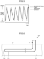
- FIG. 5 is a graph presenting an example of changes over time of detection values of pressure acquired by the pressure measurement device 10A of the present embodiment and a conventional pressure sensor.
- This graph indicates the measurement results of the pressure of a test fluid in an experimental facility that can schematically create pressure changes in the test fluid equivalent to changes in blood pressure caused by heart beats. From FIG. 5 , it can be seen that the detection values of the pressure of the test fluid are in good agreement between the pressure measurement device 10A of the present embodiment indicated by a solid line and the conventional pressure sensor indicated by a dashed line.
- the inventors have experimentally confirmed that, according to the pressure measurement device 10A of the present embodiment, it is possible to acquire the measurement performance that is equal to or better than that of conventional pressure sensors, as in this example.
- the light receiving unit 22 receives the test light emitted from the light source 21 and transmitted in the optical fiber 11 including the sensor part 11a (sensor optical fiber).
- the transmission loss of the test light at the sensor part 11a increases as the external force such as fluid pressure acting on the sensor part 11a increases.
- the control unit 30 measures the blood pressure (fluid pressure in a living body) acting on the sensor part 11a based on the optical intensity of the test light received at the light receiving unit 22.
- the pressure measurement device 10A can be achieved by a more compact and simpler configuration with optical fibers being the base.
- the senor part 11a may be a plastic fiber.
- the sensor part 11a can be configured more flexibly, so that the increment ratio of the transmission loss of the test light to the increment in the fluid pressure in the sensor part 11a, that is, the rate of increase, can be made larger.
- such a configuration can increase the detection sensitivity of the sensor part 11a for the fluid pressure.
- the sensor part 11a may be the optical fiber that transmits the test light with a loss of 0.3 [dB/m] or more.
- the sensor part 11a may also have the curved part 11a1.
- the sensor part 11a may include the plurality of nanostructures 11p.
- the delivery optical fiber 11d between the sensor part 11a and the light source 21 is a multi-mode optical fiber, while the sensor part 11a may be a single-mode optical fiber.
- the test light tends to leak more easily from the sensor part 11a, so that the detection sensitivity of the sensor part 11a for the fluid pressure can be increased.
- the light receiving unit 22 may also receive the test light that is input into the optical fiber 11 from the light source 21 via the end part 11e1 (one end) and output from the end part 11e2 (other end) via the sensor part 11a.
- the intensity of received light can be increased, and thus the measurement accuracy can be further improved, compared to a configuration in which the light receiving unit 22 receives light reflected at one end of the optical fiber 11, for example.
- the sensor part 11a measures the pressure of the saline solution F2 (ex vivo fluid) to which the blood pressure (pressure of an in vivo fluid) is propagated.
- the configuration of the present embodiment can be applied to an invasive blood pressure measurement device that indirectly measures the pressure of an in vivo fluid via an ex vivo fluid by the sensor part 11a located outside a living body.
- FIG. 6 is a schematic diagram of a part of a pressure measurement device 10B according to a second embodiment, which is a cross-sectional view along the longitudinal direction of an optical fiber 11 in a blood vessel V.
- the optical fiber 11 of the present embodiment is optically connected to a light source 21 and a light receiving unit 22, as in the first embodiment described above.
- test light input into the optical fiber 11 from the light source 21 is also transmitted in the optical fiber 11 including a sensor part 11a, and received at the light receiving unit 22.
- a control unit 30 calculates the pressure acted on the sensor part 11a based on the optical intensity of the test light received at the light receiving unit 22.
- the optical fiber 11 is inserted into the blood vessel V.
- the blood F1 is an example of an in vivo fluid, which may also be referred to as a first fluid.
- a length L of the sensor part 11a is preferable to be between 1 [cm] and 4 [cm], both inclusive, and a curvature radius R of a curved part 11a1 (radius of the central axis of the sensor part 11a, see FIG. 2 ) to be between 50 [um] and 200 [pm], both inclusive.
- the area of such a curvature radius R is an area where the bending loss increases sensitively to the pressure, which further improves the sensor sensitivity to the pressure.
- the pressure measurement device 10B of the present embodiment can be applied to an invasive blood pressure measurement device that directly measures the pressure of an in vivo fluid by the sensor part 11a located inside a living body.
- FIG. 7 is a schematic diagram of a part of a pressure measurement device 10C according to a third embodiment, which is a cross-sectional view along the longitudinal direction of an optical fiber 11.
- the optical fiber 11 of the present embodiment is optically connected to a light source 21 and a light receiving unit 22, as in the first embodiment described above.
- test light input into the optical fiber 11 from the light source 21 is also transmitted in the optical fiber 11 including a sensor part 11a, and received at the light receiving unit 22.
- a control unit 30 calculates the pressure acted on the sensor part 11a based on the optical intensity of the test light received at the light receiving unit 22.
- the sensor part 11a of the present embodiment is inserted into the blood vessel V, as in the second embodiment described above.
- the pressure measurement device 10C includes a tubular member 14 that surrounds the optical fiber 11.
- the tubular member 14 houses the optical fiber 11 inside the tube.
- the tubular member 14 surrounds both outward path and return path of the optical fiber 11 to/from the sensor part 11a, and the sensor part 11a is exposed from the tip of the tubular member 14.
- the tubular member 14 protects the optical fiber 11.
- the optical fiber 11 penetrates through a fixing member 14a.
- the fixing member 14a positions the optical fiber 11 and the tubular member 14 in prescribed relative positions.
- the fixing member 14a fixes the optical fiber 11 and the tubular member 14 such that the optical fiber 11 is separated from the peripheral wall of the tubular member 14 at least at the position where the fixing member 14a is provided, and that the outward path and the return path of the optical fiber 11 are separated from each other.
- the pressure measurement device 10C in the example of FIG. 7 has only one fixing member 14a, the pressure measurement device 10C is not limited thereto and may have a plurality of fixing members 14a disposed with a space provided therebetween along the longitudinal direction of the tubular member 14.
- the fixing member 14a is an adhesive, for example, but not limited thereto.
- the tubular member 14 exhibits flexibility and elasticity.
- the subassembly having the tubular member 14 and the optical fiber 11 can be given moderate elasticity, and thus moderate followability along the blood vessel V. Therefore, it is possible to acquire such an effect that the sensor part 11a is easily inserted into the blood vessel V and also easily removed from the blood vessel V.
- the tubular member 14 is made of a metallic material or a synthetic resin material, for example.
- the tubular member 14 is also an example of a support member that exhibits flexibility and supports the optical fiber 11.
- the pressure measurement device 10C of the present embodiment can be applied to an invasive blood pressure measurement device that directly measures the pressure of an in vivo fluid by the sensor part 11a located inside a living body.
- FIG. 8 is a schematic diagram of a part of a pressure measurement device 10D according to a modification of the third embodiment, which is a cross-sectional view along the longitudinal direction of an optical fiber 11 in a blood vessel V.
- the optical fiber 11 of the present modification is optically connected to a light source 21 and a light receiving unit 22, as in the first embodiment described above.
- test light input into the optical fiber 11 from the light source 21 is also transmitted in the optical fiber 11 including a sensor part 11a, and received at the light receiving unit 22.
- a control unit 30 calculates the pressure acted on the sensor part 11a based on the optical intensity of the test light received at the light receiving unit 22.
- the sensor part 11a of the present modification is inserted into a blood vessel V, as in the third embodiment described above.
- a cover 14c that is a tip part (one part) of a tubular member 14D covers the sensor part 11a.
- an opening 14b is provided in the peripheral wall (sidewall) of the cover 14c.
- the sensor part 11a comes in contact with the blood F1 that is introduced into the cover 14c from the blood vessel V via the opening 14b.
- the sensor part 11a is located in the blood.
- a fixing member 14a sections the inside of the tube of the tubular member 14 into a space S1 and a space S2 that is opened by the opening 14b. At least a part of the sensor part 11a is disposed in the space S2. With such a configuration, the sensor part 11a along with the optical fiber 11 can be protected by the tubular member 14D.
- the cover 14c may be configured with a member that is different from the tubular member 14 and attached to the tubular member 14.
- the pressure measurement device 10D of the present modification can be applied to an invasive blood pressure measurement device that directly measures the pressure of an in vivo fluid by the sensor part 11a located inside a living body.
- FIG. 9 is a schematic diagram of a pressure measurement device 10E according to a fourth embodiment, which is a plan view illustrating a state being attached outside a living body A.
- An optical fiber 11 of the present embodiment is optically connected to a light source 21 and a light receiving unit 22, as in the first embodiment described above.
- test light input into the optical fiber 11 from the light source 21 is also transmitted in the optical fiber 11 including a sensor part 11a, and received at the light receiving unit 22.
- a control unit 30 calculates the pressure acted on the sensor part 11a based on the optical intensity of the test light received at the light receiving unit 22.
- the sensor part 11a is disposed, together with a pad 15 and a cuff 16, on the outer skin of the living body A, such as an arm, for example.
- the pad 15 exhibits flexibility and has a sheet-like shape.
- the pad 15 is placed on the outer skin of the living body A while being in contact therewith.
- the sensor part 11a (optical fiber 11) is disposed on the opposite side of the outer skin of the living body A with respect to the pad 15. In other words, the pad 15 is interposed between the sensor part 11a and the outer skin of the living body A.
- the sensor part 11a is fixed to the pad 15 by, for example, an adhesive or the like.
- the cuff 16 is wrapped around the living body A, for example, around the arm, so as to cover the pad 15 and the sensor part 11a.
- the sensor part 11a is bent a plurality of times via a plurality of curved parts 11a1. Such a configuration can expand the area where sensing is possible.
- FIG. 10 is a cross-sectional view of the pressure measurement device 10E perpendicular to the pad 15. As illustrated in FIG. 10 , the pad 15, the sensor part 11a, and the cuff 16 are stacked in this order on the outer skin of the living body A. The sensor part 11a is disposed between the pad 15 and the cuff 16. The pad 15, the sensor part 11a, and the cuff 16 may or may not be fixed to each other by an adhesive or the like.
- the cuff 16 has a space S3 capable of housing gas G such as air, for example, provided between a sheet 16a close to the living body A and a sheet 16a far from the living body A.
- the space S3 is connected to an electric pump and an electric valve, not illustrated.
- the cuff 16 is configured such that the pressure of the gas G in the space S3 can be changed by controlling the electric pump and the electric valve.
- the cuff 16 is configured to allow the pressure of the gas G in the space S3 to increase and then to decrease gradually over time, for example.
- control unit 30 can acquire the maximum blood pressure and the minimum blood pressure by well-known oscillometric methods in blood pressure monitors using the cuff 16, for example, based on the detection values of the sensor part 11a or the changes over time of the blood pressure pulsation acquired from the detection values.
- the pressure measurement device 10E of the present embodiment can be applied to a non-invasive blood pressure measurement device that indirectly measures the pressure of an in vivo fluid via the living body A by the sensor part 11a located outside the living body.
- FIGS. 11 and 12 are schematic diagrams of a pressure measurement device 10F according to a fifth embodiment.
- the pressure measurement device 10F measures not the pressure of a fluid in the living body A but the pressure acting on a sensor part 11a of an optical fiber 11 from a valve part Va of the living body A, that is, the pressure received from a body part in the living body.
- the valve part Va has a constriction part (throat), and the sensor part 11a penetrates through the constriction.
- the valve part Va is, for example, the heart valve, the pylorus of the stomach, or the like.
- FIG. 11 illustrates a state where the constriction part is widened relatively large, with no pressure acting on the sensor part 11a from the valve part Va, that is, from the living body A.
- FIG. 12 illustrates a state where the constriction part is narrowed relatively small, with pressure acting on the sensor part 11a from the valve part Va.
- the control unit 30 can calculate the pressure acted on the sensor part 11a corresponding to the intensity of light received at the light receiving unit 22 based on a correlation between the intensity of the light received at the light receiving unit 22 acquired in advance experimentally and the pressure acted on the sensor part 11a from the valve part Va.
- the pressure measurement device 10F can also measure the force (load) acted on the sensor part 11a from the valve part Va.
- the pressure measurement device 10F can also function as an in vivo force measurement device (load measurement device).
- FIG. 13 is a cross-sectional view perpendicular to the longitudinal direction of a sensor part 11a according to a modification of the embodiments.
- an outer periphery 11a2 of the sensor part 11a that is, an outer periphery 11a2 of a cladding 11c, may be provided with an uneven structure including concave or convex parts.
- the uneven structure can also be referred to as structural fluctuation.
- the size of the uneven structure such as the length of the uneven structure in the longitudinal direction, the spacing, and the height difference in the radial direction, for example, to appropriate values, the transmission loss for the test light at the sensor part 11a can be made to 0.3 dB/m or more.
- the size of the concave and convex of the uneven structure is preferable to be between 5 [nm] and 100 [nm], both inclusive.
- FIG. 13 illustrates a deviation h of the average radius of the outer periphery 11a2 from a circumference C in the cross section perpendicular to the longitudinal direction of the sensor part 11a.
- the deviation h is also preferable to be between 5 [nm] and 100 [nm], both inclusive.
- the uneven structure may be provided on the outer periphery of the core 11b.
- the sensor part 11a can also be made of plastic fibers, for example.
- the configurations of the embodiments and modifications described above can also be applied to measurement of pressure of in vivo fluids other than blood, measurement of pressure received from body parts in a living body other than the valve part such as the heart valve, the pylorus of the stomach, and the like.
- the support member is not limited to the tubular member, but may be a rod-shaped member or the like that exhibits flexibility, for example.
- the optical fiber may extend linearly or spirally along the outer periphery of the support member.
- the optical fiber may be housed in a linear or helical groove provided on the outer periphery of the support member.
- optical fibers with different mode transmission states from each other may be applied to the sensor part and the delivery optical fiber such that mode conversion occurs at the connection point (boundary) between the sensor part (sensor optical fiber) and the delivery optical fiber between the sensor part and the light source.
- mode conversion at the connection point depends on the external force
- the mode mismatch state also depends on the external force. Therefore, the degree of leakage of the test light at the sensor part becomes more sensitive to the external force, which results in increasing the sensitivity of the sensor part further to the pressure in the living body.
- the present invention can be utilized for in vivo pressure measurement devices.
Landscapes
- Health & Medical Sciences (AREA)
- Life Sciences & Earth Sciences (AREA)
- Physics & Mathematics (AREA)
- Heart & Thoracic Surgery (AREA)
- Molecular Biology (AREA)
- Veterinary Medicine (AREA)
- Biophysics (AREA)
- Pathology (AREA)
- Engineering & Computer Science (AREA)
- Biomedical Technology (AREA)
- Cardiology (AREA)
- Medical Informatics (AREA)
- Public Health (AREA)
- Surgery (AREA)
- Animal Behavior & Ethology (AREA)
- General Health & Medical Sciences (AREA)
- Physiology (AREA)
- Vascular Medicine (AREA)
- General Physics & Mathematics (AREA)
- Hematology (AREA)
- Measuring Pulse, Heart Rate, Blood Pressure Or Blood Flow (AREA)
- Measuring Fluid Pressure (AREA)
- Measuring And Recording Apparatus For Diagnosis (AREA)
Abstract
Description
- The present invention relates to an in vivo pressure measurement device.
- Conventionally, an invasive blood pressure monitor as disclosed in
Patent Literature 1 and a non-invasive blood pressure monitor as disclosed in Patent literature 2 are known. -
- Patent Literature 1:
Japanese Patent Application Laid-open No. 2018-187146 - Patent Literature 2:
Japanese Patent Application Laid-open No. 2020-028478 - In both types of blood pressure monitors, it would be beneficial if the size thereof can be made smaller and the structure thereof can be more simplified, for example.
- In addition to blood pressure, it would be even more beneficial if pressure and forces acting in a living body can be measured as well.
- It is therefore an object of the present invention, for example, to acquire a more improved and new in vivo pressure measurement device.
- An in vivo pressure measurement device according to the present invention includes, for example: a light source configured to output test light; an optical fiber, to which the test light is input, at least partially including a sensor optical fiber configured to transmit the test light with a loss of 0.3 dB/m or more; and a light receiving unit configured to receive the test light transmitted through the sensor optical fiber, wherein the in vivo pressure measurement device is configured to measure pressure in a living body acting on the sensor optical fiber based on intensity of the test light received at the light receiving unit.
- In the in vivo pressure measurement device, the pressure in the living body may pressure of a fluid in the living body.
- In the in vivo pressure measurement device, the sensor optical fiber may be a plastic fiber.
- In the in vivo pressure measurement device, the sensor optical fiber may include a curved part.
- In the in vivo pressure measurement device, the sensor optical fiber may configured to be inserted into the living body.
- In the in vivo pressure measurement device, the sensor optical fiber may be configured to measure pressure of an ex vivo fluid to which pressure of an in vivo fluid is propagated.
- The in vivo pressure measurement device may include a flexible support member configured to extend along the optical fiber and support the optical fiber.
- The in vivo pressure measurement device may include a tubular member configured to house the optical fiber.
- In the in vivo pressure measurement device, the tubular member may be flexible.
- The in vivo pressure measurement device may include a cover configured to cover the sensor optical fiber in a state capable of introducing an in vivo fluid or an ex vivo fluid to which pressure of the in vivo fluid is propagated.
- In the in vivo pressure measurement device, the sensor optical fiber may be located outside the living body, and configured to measure pressure of an in vivo fluid indirectly acting on the sensor optical fiber via the living body.
- In the in vivo pressure measurement device, the sensor optical fiber may be configured to be disposed between the living body and a cuff located outside the living body, the cuff being configured to constrict a blood vessel in the living body by internal air pressure and change the air pressure.
- In the in vivo pressure measurement device, the optical fiber may include: the sensor optical fiber; and a delivery optical fiber connected to the sensor optical fiber and having a lower transmission loss than the sensor optical fiber does.
- In the in vivo pressure measurement device, in wavelengths of the test light, the sensor optical fiber may be a single-mode optical fiber, and the delivery optical fiber between the sensor optical fiber and the light source may be a multi-mode optical fiber.
- In the in vivo pressure measurement device, the sensor optical fiber and the delivery optical fiber may be fusion-spliced.
- In the in vivo pressure measurement device, the light receiving unit may be configured to receive the test light input from one end of the optical fiber and output from another end of the optical fiber.
- In the in vivo pressure measurement device, the sensor optical fiber may include a core, a cladding surrounding the core, and a plurality of nanostructures near an interface between the core and the cladding, and the nanostructure may have a cross-sectional diameter of 100 nm or less in a cross section perpendicular to a longitudinal direction of the sensor optical fiber.
- In the in vivo pressure measurement device, the nanostructure may be a microparticle, a tube or a void.
- In the in vivo pressure measurement device, an outer periphery of the sensor optical fiber may include an uneven structure of 5 nm to 100 nm.
- The in vivo pressure measurement device may include an arithmetic processing unit configured to acquire the pressure acting on the sensor optical fiber based on the intensity of the test light.
- Moreover, an in vivo pressure measurement device according to the present invention includes, for example: a light source configured to output test light; an optical fiber, to which the test light is input, including a sensor part from which light leaks due to an applied external force; and a light receiving unit configured to receive the test light transmitted through the sensor part, wherein the in vivo pressure measurement device is configured to measure pressure in a living body acting on the sensor part based on intensity of the test light received at the light receiving unit.
- In the in vivo pressure measurement device, a transmission loss in the sensor part may increase as the external force acting on the sensor part increases. Advantageous Effects of Invention
- According to the present invention, for example, it is possible to acquire an improved and new in vivo pressure measurement device.
-
-
FIG. 1 is an exemplary schematic diagram of an in vivo pressure measurement device according to a first embodiment. -
FIG. 2 is an exemplary schematic diagram of an optical fiber according to the embodiment. -
FIG. 3 is an exemplary and schematic cross-sectional view taken along the longitudinal direction of a part of a sensor part according to the embodiment. -
FIG. 4 is an exemplary and schematic cross-sectional view perpendicular to the longitudinal direction of the sensor part according to the embodiment. -
FIG. 5 is a graph presenting an example of change over time of detection values of pressure acquired by the in vivo pressure measurement device of the embodiment and a conventional pressure sensor. -
FIG. 6 is an exemplary schematic diagram of an in vivo pressure measurement device according to a second embodiment. -
FIG. 7 is an exemplary schematic diagram of an in vivo pressure measurement device according to a third embodiment. -
FIG. 8 is an exemplary schematic diagram of an in vivo pressure measurement device according to a modification of the third embodiment. -
FIG. 9 is an exemplary schematic diagram of an in vivo pressure measurement device according to a fourth embodiment. -
FIG. 10 is an exemplary and schematic diagram of a part of the in vivo pressure measurement device according to the fourth embodiment. -
FIG. 11 is an exemplary schematic diagram of an in vivo pressure measurement device according to a fifth embodiment, which illustrates a state where no pressure is acting on the sensor part from a living body. -
FIG. 12 is an exemplary schematic diagram of the in vivo pressure measurement device according to the fifth embodiment, which illustrates a state where pressure is acting on the sensor part from the living body. -
FIG. 13 is an exemplary and schematic cross-sectional view perpendicular to the longitudinal direction of the sensor part according to a modification of the embodiment. Description of Embodiments - Hereinafter, exemplary embodiments and modifications of the present invention will be disclosed. The configurations of the embodiments and modifications presented below as well as the actions and results (effects) brought about by such configurations are examples. The present invention can also be achieved by configurations other than those disclosed in the following embodiments and modifications. In addition, according to the present invention, it is possible to acquire at least one of the various kinds of effects (including derivative effects) achieved by the configurations.
- The embodiments and modifications described hereinafter have similar constituent elements. Therefore, according to the configuration of each of the embodiments and modifications, it is possible to acquire similar actions and effects based on the similar constituent elements. Furthermore, hereinafter, similar reference signs may be applied to the similar constituent elements, and duplicated explanations may be omitted.
- In the present descriptions, ordinal numbers are assigned for convenience in order to distinguish components, members, parts, and the like, and do not indicate priority or order thereof.
-
FIG. 1 is a schematic diagram of apressure measurement device 10A according to a first embodiment. In the present embodiment, thepressure measurement device 10A is a device that measures blood pressure as fluid pressure in a living body, which is an invasive blood pressure measurement device. Note that blood is an example of a fluid in a living body A as a target of pressure measurement, and may also be referred to as a first fluid. Thepressure measurement device 10A is an example of an in vivo pressure measurement device. - As illustrated in
FIG. 1 , thepressure measurement device 10A includes anoptical fiber 11, atube set 12, acatheter 13, alight source 21, alight receiving unit 22, and acontrol unit 30. - An end part 11e1 in the longitudinal direction of the
optical fiber 11 is optically connected to thelight source 21, and an end part 11e2 in the longitudinal direction of theoptical fiber 11 is optically connected to thelight receiving unit 22. Test light emitted from thelight source 21 is input into theoptical fiber 11 from the end part 11e1, transmitted through theoptical fiber 11 including asensor part 11a, output outside theoptical fiber 11 from the end part 11e2, and received at thelight receiving unit 22. The end part 11e1 is an example of one end, and the end part 11e2 is an example of the other end. - The
light source 21 has, for example, a laser diode that outputs light with a wavelength of 400 [nm] or more and 500 [nm] or less, for example. Thelight source 21 may also output optical pulses intermittently at prescribed time intervals. - The
light receiving unit 22 has, for example, a photodiode, and detects intensity of light input from theoptical fiber 11, that is, intensity of the light passing through thesensor part 11a. Thelight receiving unit 22 can also be referred to as a detection unit. - The
control unit 30 can acquire the intensity of the light received at thelight receiving unit 22. In addition, thecontrol unit 30 can switch emission and non-emission of test light at thelight source 21 and change the output state of the test light. - The
catheter 13 is placed on the surface of the living body A, and its tip (not illustrated) is inserted into a blood vessel V. - The inside of the tube set 12 is filled with a fluid different from blood, such as a saline solution F2, for example. The
catheter 13 and the tube set 12 are configured such that the blood pressure inside the blood vessel V is propagated to the saline solution F2. The saline solution F2 is an example of an ex vivo fluid, which may also be referred to as a second fluid. - The tube set 12 includes a
tube 12a and achamber 12b expanded from thetube 12a. Thechamber 12b has thesensor part 11a of theoptical fiber 11 inserted thereto. As is apparent fromFIG. 1 , the tube set 12 is located outside the living body A. Therefore, in the present embodiment, thesensor part 11a is located outside the living body A. Thesensor part 11a detects the pressure of the saline solution F2 to which the pressure of blood is propagated. Note that the tube set 12 may not have thechamber 12b, and thesensor part 11a may be inserted into thetube 12a. -
FIG. 2 is a schematic diagram of theoptical fiber 11. As illustrated inFIG. 2 , theoptical fiber 11 includes thesensor part 11a and two deliveryoptical fibers 11d. Thesensor part 11a is an optical fiber interposed between the two deliveryoptical fibers 11d. In other words, one deliveryoptical fiber 11d, thesensor part 11a that is an optical fiber, and the other deliveryoptical fiber 11d are mechanically and optically connected in series. The transmission loss of the deliveryoptical fiber 11d is lower than the transmission loss of thesensor part 11a. The effective relative refractive-index difference of the deliveryoptical fiber 11d is larger than the effective relative refractive-index difference of thesensor part 11a. Furthermore, at aboundary 11f between thesensor part 11a and the deliveryoptical fiber 11d, thesensor part 11a and the deliveryoptical fiber 11d are fusion-spliced. Thesensor part 11a is an example of a sensor optical fiber. -
FIG. 3 is a cross-sectional view of a part of thesensor part 11a along the longitudinal direction, andFIG. 4 is a cross-sectional view of thesensor part 11a perpendicular to the longitudinal direction. - As is apparent from
FIGS. 3 and 4 , thesensor part 11a includes a core 11b and acladding 11c that surrounds the core 11b and has a lower refractive index than that of the core 11b. - The diameter of the core 11b and the relative refractive-index difference of the core 11b with respect to the
cladding 11c are set such that thesensor part 11a can transmit test light in a single mode. Furthermore, thecladding 11c may be surrounded by a coating (not illustrated). The coating in this case exhibits transparency to the test light. - Furthermore, as an example, the diameter of the cladding, that is, the outer diameter of the core wire, is the same for the
sensor part 11a and the deliveryoptical fiber 11d. The diameter (outer diameter) of the core may also be the same or different for thesensor part 11a and the deliveryoptical fiber 11d. As an example, the diameter of the core of the deliveryoptical fiber 11d may be larger than the diameter of the core 11b of thesensor part 11a. Furthermore, the deliveryoptical fiber 11d may be a multi-mode optical fiber that transmits the test light in a multi-mode. - The
sensor part 11a and the deliveryoptical fiber 11d are what is called plastic fibers made of a synthetic resin material transparent to the test light, such as methacrylic resin or fluororesin. However, not limited to this, thesensor part 11a and the deliveryoptical fiber 11d may be glass optical fibers made of a quartz glass material. Thesensor part 11a and the deliveryoptical fiber 11d may also be made of materials different from each other. - Furthermore, as illustrated in
FIGS. 3 and 4 , thesensor part 11a may include a plurality ofnanostructures 11p near the interface between the core 11b and thecladding 11c. However, distribution ofsuch nanostructures 11p is an example, and thenanostructures 11p may exist throughout the entire radial direction of thecladding 11c within thesensor part 11a. Each of thenanostructures 11p may contain fillers (for example, particles such as fine particles or cylindrical tubes) and voids (for example, microscopic spaces of air other than tubes or fine particles), and may contain at least two kinds of those examples. Thenanostructure 11p, for example, has a cross-sectional diameter of 100 [nm] or less in the cross section perpendicular to the longitudinal direction of thesensor part 11a. In this case, the loss in thesensor part 11a tends to increase compared to the case without fillers and voids. Fillers and voids may be contained more in thecladding 11c than in the core 11b of thesensor part 11a. - Through the intensive sturdies of the inventors, it is found that in the
sensor part 11a with such a configuration, the test light is scattered by thenanostructures 11p, which makes it more difficult for the test light to be confined in the core 11b than in a configuration without thenanostructures 11p, that is, the test light tends to leak from the core 11b. In this case, it is also found that the greater the external force acting on thesensor part 11a, the greater the leakage of the test light from thesensor part 11a, that is, the greater the transmission loss in thesensor part 11a. Furthermore, for such asensor part 11a where the test light tends to leak from the core 11b, it is also found that, when an external force is applied, the transmission loss changes more sensitively in response to the external force. As an example, it is found that such characteristics become more prominent when the transmission loss for the test light at thesensor part 11a is 0.3 [dB/m] or more. This is because light leaks to the outside of thecladding 11c when the transmission loss is 0.3 [dB/m] or more, and light sensitively reacts to changes in thenanostructures 11p near thecladding 11c caused due to the external pressure, which significantly affects the transmission loss. - From these characteristics of the
sensor part 11a, thecontrol unit 30 can calculate the pressure of the saline solution F2 at thesensor part 11a corresponding to the intensity of light received at thelight receiving unit 22, and thus the pressure of blood, that is, the blood pressure, based on a correlation between the intensity of light received at thelight receiving unit 22 acquired in advance experimentally and the pressure acted on thesensor part 11a. Thecontrol unit 30 is an example of an arithmetic processing unit. - Furthermore, as illustrated in
FIG. 2 , thesensor part 11a has a curved part 11a1 folded in a U-like shape. The curved part 11a1 can also be referred to as a bent part or a folded part. Through the intensive studies of the inventors, for thesensor part 11a, it is found that a length L of thesensor part 11a is preferable to be between 1 [cm] and 4 [cm], both inclusive, and a curvature radius R of the curved part 11a1 (radius of the central axis of thesensor part 11a) to be between 50 [um] and 200 [pm], both inclusive. -
FIG. 5 is a graph presenting an example of changes over time of detection values of pressure acquired by thepressure measurement device 10A of the present embodiment and a conventional pressure sensor. This graph indicates the measurement results of the pressure of a test fluid in an experimental facility that can schematically create pressure changes in the test fluid equivalent to changes in blood pressure caused by heart beats. FromFIG. 5 , it can be seen that the detection values of the pressure of the test fluid are in good agreement between thepressure measurement device 10A of the present embodiment indicated by a solid line and the conventional pressure sensor indicated by a dashed line. The inventors have experimentally confirmed that, according to thepressure measurement device 10A of the present embodiment, it is possible to acquire the measurement performance that is equal to or better than that of conventional pressure sensors, as in this example. - As described above, in the present embodiment, the
light receiving unit 22 receives the test light emitted from thelight source 21 and transmitted in theoptical fiber 11 including thesensor part 11a (sensor optical fiber). The transmission loss of the test light at thesensor part 11a increases as the external force such as fluid pressure acting on thesensor part 11a increases. Thecontrol unit 30 measures the blood pressure (fluid pressure in a living body) acting on thesensor part 11a based on the optical intensity of the test light received at thelight receiving unit 22. - With such a configuration, the
pressure measurement device 10A can be achieved by a more compact and simpler configuration with optical fibers being the base. - In addition, as in the present embodiment, the
sensor part 11a may be a plastic fiber. - With such a configuration, for example, the
sensor part 11a can be configured more flexibly, so that the increment ratio of the transmission loss of the test light to the increment in the fluid pressure in thesensor part 11a, that is, the rate of increase, can be made larger. In other words, such a configuration can increase the detection sensitivity of thesensor part 11a for the fluid pressure. - Furthermore, as in the present embodiment, the
sensor part 11a may be the optical fiber that transmits the test light with a loss of 0.3 [dB/m] or more. - As in the present embodiment, the
sensor part 11a may also have the curved part 11a1. - In addition, as in the present embodiment, the
sensor part 11a may include the plurality ofnanostructures 11p. - Furthermore, in the present embodiment, the delivery
optical fiber 11d between thesensor part 11a and thelight source 21 is a multi-mode optical fiber, while thesensor part 11a may be a single-mode optical fiber. - With such a configuration, for example, the test light tends to leak more easily from the
sensor part 11a, so that the detection sensitivity of thesensor part 11a for the fluid pressure can be increased. - Furthermore, as in the present embodiment, the
light receiving unit 22 may also receive the test light that is input into theoptical fiber 11 from thelight source 21 via the end part 11e1 (one end) and output from the end part 11e2 (other end) via thesensor part 11a. - With such a configuration, the intensity of received light can be increased, and thus the measurement accuracy can be further improved, compared to a configuration in which the
light receiving unit 22 receives light reflected at one end of theoptical fiber 11, for example. - Furthermore, in the present embodiment, the
sensor part 11a measures the pressure of the saline solution F2 (ex vivo fluid) to which the blood pressure (pressure of an in vivo fluid) is propagated. - The configuration of the present embodiment can be applied to an invasive blood pressure measurement device that indirectly measures the pressure of an in vivo fluid via an ex vivo fluid by the
sensor part 11a located outside a living body. -
FIG. 6 is a schematic diagram of a part of apressure measurement device 10B according to a second embodiment, which is a cross-sectional view along the longitudinal direction of anoptical fiber 11 in a blood vessel V. Theoptical fiber 11 of the present embodiment is optically connected to alight source 21 and alight receiving unit 22, as in the first embodiment described above. In other words, in the present embodiment, test light input into theoptical fiber 11 from thelight source 21 is also transmitted in theoptical fiber 11 including asensor part 11a, and received at thelight receiving unit 22. Acontrol unit 30 calculates the pressure acted on thesensor part 11a based on the optical intensity of the test light received at thelight receiving unit 22. - As illustrated in
FIG. 6 , in the present embodiment, theoptical fiber 11 is inserted into the blood vessel V. With such a configuration, the higher the pressure of blood F1 that is a fluid in the blood vessel V, the greater the transmission loss of the test light at thesensor part 11a. The blood F1 is an example of an in vivo fluid, which may also be referred to as a first fluid. - Through the intensive studies of the inventors, for the
sensor part 11a also in thepressure measurement device 10B of the present embodiment, it is found that a length L of thesensor part 11a (seeFIG. 2 ) is preferable to be between 1 [cm] and 4 [cm], both inclusive, and a curvature radius R of a curved part 11a1 (radius of the central axis of thesensor part 11a, seeFIG. 2 ) to be between 50 [um] and 200 [pm], both inclusive. The area of such a curvature radius R is an area where the bending loss increases sensitively to the pressure, which further improves the sensor sensitivity to the pressure. - With the present embodiment, it is possible to acquire the effects similar to those of the first embodiment described above. The
pressure measurement device 10B of the present embodiment can be applied to an invasive blood pressure measurement device that directly measures the pressure of an in vivo fluid by thesensor part 11a located inside a living body. -
FIG. 7 is a schematic diagram of a part of apressure measurement device 10C according to a third embodiment, which is a cross-sectional view along the longitudinal direction of anoptical fiber 11. Theoptical fiber 11 of the present embodiment is optically connected to alight source 21 and alight receiving unit 22, as in the first embodiment described above. In other words, in the present embodiment, test light input into theoptical fiber 11 from thelight source 21 is also transmitted in theoptical fiber 11 including asensor part 11a, and received at thelight receiving unit 22. Acontrol unit 30 calculates the pressure acted on thesensor part 11a based on the optical intensity of the test light received at thelight receiving unit 22. Thesensor part 11a of the present embodiment is inserted into the blood vessel V, as in the second embodiment described above. - As illustrated in
FIG. 7 , in the present embodiment, thepressure measurement device 10C includes atubular member 14 that surrounds theoptical fiber 11. In other words, thetubular member 14 houses theoptical fiber 11 inside the tube. Thetubular member 14 surrounds both outward path and return path of theoptical fiber 11 to/from thesensor part 11a, and thesensor part 11a is exposed from the tip of thetubular member 14. Thetubular member 14 protects theoptical fiber 11. - The
optical fiber 11 penetrates through a fixingmember 14a. The fixingmember 14a positions theoptical fiber 11 and thetubular member 14 in prescribed relative positions. In the present embodiment, the fixingmember 14a, for example, fixes theoptical fiber 11 and thetubular member 14 such that theoptical fiber 11 is separated from the peripheral wall of thetubular member 14 at least at the position where the fixingmember 14a is provided, and that the outward path and the return path of theoptical fiber 11 are separated from each other. While thepressure measurement device 10C in the example ofFIG. 7 has only one fixingmember 14a, thepressure measurement device 10C is not limited thereto and may have a plurality of fixingmembers 14a disposed with a space provided therebetween along the longitudinal direction of thetubular member 14. The fixingmember 14a is an adhesive, for example, but not limited thereto. - Furthermore, the
tubular member 14 exhibits flexibility and elasticity. Thus, with such a configuration, by setting the specifications of thetubular member 14 appropriately, for example, the subassembly having thetubular member 14 and theoptical fiber 11 can be given moderate elasticity, and thus moderate followability along the blood vessel V. Therefore, it is possible to acquire such an effect that thesensor part 11a is easily inserted into the blood vessel V and also easily removed from the blood vessel V. Thetubular member 14 is made of a metallic material or a synthetic resin material, for example. Thetubular member 14 is also an example of a support member that exhibits flexibility and supports theoptical fiber 11. - With the present embodiment, it is also possible to acquire the effects similar to those of the first embodiment described above. The
pressure measurement device 10C of the present embodiment can be applied to an invasive blood pressure measurement device that directly measures the pressure of an in vivo fluid by thesensor part 11a located inside a living body. -
FIG. 8 is a schematic diagram of a part of apressure measurement device 10D according to a modification of the third embodiment, which is a cross-sectional view along the longitudinal direction of anoptical fiber 11 in a blood vessel V. Theoptical fiber 11 of the present modification is optically connected to alight source 21 and alight receiving unit 22, as in the first embodiment described above. In other words, in the present modification, test light input into theoptical fiber 11 from thelight source 21 is also transmitted in theoptical fiber 11 including asensor part 11a, and received at thelight receiving unit 22. Acontrol unit 30 calculates the pressure acted on thesensor part 11a based on the optical intensity of the test light received at thelight receiving unit 22. Furthermore, thesensor part 11a of the present modification is inserted into a blood vessel V, as in the third embodiment described above. - As illustrated in
FIG. 8 , in the present modification, acover 14c that is a tip part (one part) of atubular member 14D covers thesensor part 11a. Note, however, that anopening 14b is provided in the peripheral wall (sidewall) of thecover 14c. Thereby, thesensor part 11a comes in contact with the blood F1 that is introduced into thecover 14c from the blood vessel V via theopening 14b. In other words, thesensor part 11a is located in the blood. Furthermore, a fixingmember 14a sections the inside of the tube of thetubular member 14 into a space S1 and a space S2 that is opened by theopening 14b. At least a part of thesensor part 11a is disposed in the space S2. With such a configuration, thesensor part 11a along with theoptical fiber 11 can be protected by thetubular member 14D. Note that thecover 14c may be configured with a member that is different from thetubular member 14 and attached to thetubular member 14. - The
pressure measurement device 10D of the present modification can be applied to an invasive blood pressure measurement device that directly measures the pressure of an in vivo fluid by thesensor part 11a located inside a living body. -
FIG. 9 is a schematic diagram of apressure measurement device 10E according to a fourth embodiment, which is a plan view illustrating a state being attached outside a living body A. Anoptical fiber 11 of the present embodiment is optically connected to alight source 21 and alight receiving unit 22, as in the first embodiment described above. In other words, in the present embodiment, test light input into theoptical fiber 11 from thelight source 21 is also transmitted in theoptical fiber 11 including asensor part 11a, and received at thelight receiving unit 22. Acontrol unit 30 calculates the pressure acted on thesensor part 11a based on the optical intensity of the test light received at thelight receiving unit 22. - As illustrated in
FIG. 9 , in the present embodiment, thesensor part 11a is disposed, together with apad 15 and acuff 16, on the outer skin of the living body A, such as an arm, for example. - The
pad 15 exhibits flexibility and has a sheet-like shape. Thepad 15 is placed on the outer skin of the living body A while being in contact therewith. Thesensor part 11a (optical fiber 11) is disposed on the opposite side of the outer skin of the living body A with respect to thepad 15. In other words, thepad 15 is interposed between thesensor part 11a and the outer skin of the living body A. Thesensor part 11a is fixed to thepad 15 by, for example, an adhesive or the like. - The
cuff 16 is wrapped around the living body A, for example, around the arm, so as to cover thepad 15 and thesensor part 11a. - Furthermore, the
sensor part 11a is bent a plurality of times via a plurality of curved parts 11a1. Such a configuration can expand the area where sensing is possible. -
FIG. 10 is a cross-sectional view of thepressure measurement device 10E perpendicular to thepad 15. As illustrated inFIG. 10 , thepad 15, thesensor part 11a, and thecuff 16 are stacked in this order on the outer skin of the living body A. Thesensor part 11a is disposed between thepad 15 and thecuff 16. Thepad 15, thesensor part 11a, and thecuff 16 may or may not be fixed to each other by an adhesive or the like. - The
cuff 16 has a space S3 capable of housing gas G such as air, for example, provided between asheet 16a close to the living body A and asheet 16a far from the living body A. The space S3 is connected to an electric pump and an electric valve, not illustrated. Thecuff 16 is configured such that the pressure of the gas G in the space S3 can be changed by controlling the electric pump and the electric valve. Specifically, thecuff 16 is configured to allow the pressure of the gas G in the space S3 to increase and then to decrease gradually over time, for example. With such a configuration, thecontrol unit 30 can acquire the maximum blood pressure and the minimum blood pressure by well-known oscillometric methods in blood pressure monitors using thecuff 16, for example, based on the detection values of thesensor part 11a or the changes over time of the blood pressure pulsation acquired from the detection values. - With the present embodiment, it is also possible to acquire the effects similar to those of the first embodiment described above. The
pressure measurement device 10E of the present embodiment can be applied to a non-invasive blood pressure measurement device that indirectly measures the pressure of an in vivo fluid via the living body A by thesensor part 11a located outside the living body. -
FIGS. 11 and 12 are schematic diagrams of apressure measurement device 10F according to a fifth embodiment. Thepressure measurement device 10F measures not the pressure of a fluid in the living body A but the pressure acting on asensor part 11a of anoptical fiber 11 from a valve part Va of the living body A, that is, the pressure received from a body part in the living body. The valve part Va has a constriction part (throat), and thesensor part 11a penetrates through the constriction. The valve part Va is, for example, the heart valve, the pylorus of the stomach, or the like.FIG. 11 illustrates a state where the constriction part is widened relatively large, with no pressure acting on thesensor part 11a from the valve part Va, that is, from the living body A. On the other hand,FIG. 12 illustrates a state where the constriction part is narrowed relatively small, with pressure acting on thesensor part 11a from the valve part Va. In the state illustrated inFIG. 12 , the outer periphery of thesensor part 11a is dented due to the force received from the valve part Va, thereby increasing leakage of the test light from thesensor part 11a and increasing the transmission loss for the test light at thesensor part 11a compared to the state illustrated inFIG. 11 . Therefore, thecontrol unit 30 can calculate the pressure acted on thesensor part 11a corresponding to the intensity of light received at thelight receiving unit 22 based on a correlation between the intensity of the light received at thelight receiving unit 22 acquired in advance experimentally and the pressure acted on thesensor part 11a from the valve part Va. Note that thepressure measurement device 10F can also measure the force (load) acted on thesensor part 11a from the valve part Va. In other words, in the present embodiment, thepressure measurement device 10F can also function as an in vivo force measurement device (load measurement device). -
FIG. 13 is a cross-sectional view perpendicular to the longitudinal direction of asensor part 11a according to a modification of the embodiments. As illustrated inFIG. 13 , an outer periphery 11a2 of thesensor part 11a, that is, an outer periphery 11a2 of acladding 11c, may be provided with an uneven structure including concave or convex parts. The uneven structure can also be referred to as structural fluctuation. By setting the size of the uneven structure, such as the length of the uneven structure in the longitudinal direction, the spacing, and the height difference in the radial direction, for example, to appropriate values, the transmission loss for the test light at thesensor part 11a can be made to 0.3 dB/m or more. Through the intensive studies of the inventors, it is found that the size of the concave and convex of the uneven structure is preferable to be between 5 [nm] and 100 [nm], both inclusive. As an example of an index of the size of the uneven structure,FIG. 13 illustrates a deviation h of the average radius of the outer periphery 11a2 from a circumference C in the cross section perpendicular to the longitudinal direction of thesensor part 11a. The deviation h is also preferable to be between 5 [nm] and 100 [nm], both inclusive. Note that the uneven structure may be provided on the outer periphery of the core 11b. In addition, in the present modification, thesensor part 11a can also be made of plastic fibers, for example. - While the embodiments and modifications of the present invention are presented above, the embodiments and modifications are examples and are not intended to limit the scope of the present invention. The embodiments and modifications described above can be implemented in various other forms, and various omissions, substitutions, combinations, and changes are possible without departing from the gist of the present invention. In addition, each constituent element, shape, and other specifications (structure, type, direction, model, size, length, width, thickness, height, number, arrangement, position, material, and the like) can be changed as appropriate.
- For example, the configurations of the embodiments and modifications described above can also be applied to measurement of pressure of in vivo fluids other than blood, measurement of pressure received from body parts in a living body other than the valve part such as the heart valve, the pylorus of the stomach, and the like.
- Furthermore, the support member is not limited to the tubular member, but may be a rod-shaped member or the like that exhibits flexibility, for example. In that case, the optical fiber may extend linearly or spirally along the outer periphery of the support member. Furthermore, the optical fiber may be housed in a linear or helical groove provided on the outer periphery of the support member.
- In addition, optical fibers with different mode transmission states from each other may be applied to the sensor part and the delivery optical fiber such that mode conversion occurs at the connection point (boundary) between the sensor part (sensor optical fiber) and the delivery optical fiber between the sensor part and the light source. In this case, mode conversion at the connection point depends on the external force, and the mode mismatch state also depends on the external force. Therefore, the degree of leakage of the test light at the sensor part becomes more sensitive to the external force, which results in increasing the sensitivity of the sensor part further to the pressure in the living body.
- The present invention can be utilized for in vivo pressure measurement devices.
-
- 10A to 10F
- Pressure measurement device (in vivo pressure measurement device)
- 11
- Optical fiber
- 11a
- Sensor part (sensor optical fiber)
- 11a1
- Curved part
- 11a2
- Outer periphery
- 11b
- Core
- 11c
- Cladding
- 11d
- Delivery optical fiber
- 11e1
- End part (one end)
- 11e2
- End part (other end)
- 11f
- Boundary
- 11p
- Nanostructure
- 12
- Tube set
- 12a
- Tube
- 12b
- Chamber
- 13
- Catheter
- 14, 14D
- Tubular member (support member)
- 14a
- Fixing member
- 14b
- Opening
- 14c
- Cover
- 15
- Pad
- 16
- Cuff
- 16a
- Sheet
- 21
- Light source
- 22
- Light receiving unit
- 30
- Control unit (arithmetic processing unit)
- A
- Living body
- C
- Circumference
- F1
- Blood (in vivo fluid)
- F2
- Saline solution (ex vivo fluid)
- G
- Gas
- h
- Deviation
- L
- Length
- R
- Curvature radius
- S1 to S3
- Space
- V
- Blood vessel
- Va
- Valve part
Claims (22)
- An in vivo pressure measurement device comprising:a light source configured to output test light;an optical fiber, to which the test light is input, at least partially including a sensor optical fiber configured to transmit the test light with a loss of 0.3 dB/m or more; anda light receiving unit configured to receive the test light transmitted through the sensor optical fiber, whereinthe in vivo pressure measurement device is configured to measure pressure in a living body acting on the sensor optical fiber based on intensity of the test light received at the light receiving unit.
- The in vivo pressure measurement device according to claim 1, wherein the pressure in the living body is pressure of a fluid in the living body.
- The in vivo pressure measurement device according to claim 1 or 2, wherein the sensor optical fiber is a plastic fiber.
- The in vivo pressure measurement device according to any one of claims 1 to 3, wherein the sensor optical fiber includes a curved part.
- The in vivo pressure measurement device according to any one of claims 1 to 4, wherein the sensor optical fiber is configured to be inserted into the living body.
- The in vivo pressure measurement device according to any one of claims 1 to 4, wherein the sensor optical fiber is configured to measure pressure of an ex vivo fluid to which pressure of an in vivo fluid is propagated.
- The in vivo pressure measurement device according to any one of claims 1 to 6, comprising a flexible support member configured to extend along the optical fiber and support the optical fiber.
- The in vivo pressure measurement device according to any one of claims 1 to 7, comprising a tubular member configured to house the optical fiber.
- The in vivo pressure measurement device according to claim 8, wherein the tubular member is flexible.
- The in vivo pressure measurement device according to any one of claims 1 to 9, comprising a cover configured to cover the sensor optical fiber in a state capable of introducing an in vivo fluid or an ex vivo fluid to which pressure of the in vivo fluid is propagated.
- The in vivo pressure measurement device according to any one of claims 1 to 4, wherein the sensor optical fiber is located outside the living body, and configured to measure pressure of an in vivo fluid indirectly acting on the sensor optical fiber via the living body.
- The in vivo pressure measurement device according to claim 11, wherein the sensor optical fiber is configured to be disposed between the living body and a cuff located outside the living body, the cuff being configured to constrict a blood vessel in the living body by internal air pressure and change the air pressure.
- The in vivo pressure measurement device according to any one of claims 1 to 12, wherein the optical fiber includes:the sensor optical fiber; anda delivery optical fiber connected to the sensor optical fiber and having a lower transmission loss than the sensor optical fiber does.
- The in vivo pressure measurement device according to claim 13, wherein, in wavelengths of the test light,the sensor optical fiber is a single-mode optical fiber, andthe delivery optical fiber between the sensor optical fiber and the light source is a multi-mode optical fiber.
- The in vivo pressure measurement device according to claim 13 or 14, wherein the sensor optical fiber and the delivery optical fiber are fusion-spliced.
- The in vivo pressure measurement device according to any one of claims 1 to 15, wherein the light receiving unit is configured to receive the test light input from one end of the optical fiber and output from another end of the optical fiber.
- The in vivo pressure measurement device according to any one of claims 1 to 16, whereinthe sensor optical fiber includesa core,a cladding surrounding the core, anda plurality of nanostructures near an interface between the core and the cladding, andthe nanostructure has a cross-sectional diameter of 100 nm or less in a cross section perpendicular to a longitudinal direction of the sensor optical fiber.
- The in vivo pressure measurement device according to claim 17, wherein the nanostructure is a microparticle, a tube or a void.
- The in vivo pressure measurement device according to any one of claims 1 to 18, wherein an outer periphery of the sensor optical fiber includes an uneven structure of 5 nm to 100 nm.
- The in vivo pressure measurement device according to any one of claims 1 to 19, comprising an arithmetic processing unit configured to acquire the pressure acting on the sensor optical fiber based on the intensity of the test light.
- An in vivo pressure measurement device comprising:a light source configured to output test light;an optical fiber, to which the test light is input, including a sensor part from which light leaks due to an applied external force; anda light receiving unit configured to receive the test light transmitted through the sensor part, whereinthe in vivo pressure measurement device is configured to measure pressure in a living body acting on the sensor part based on intensity of the test light received at the light receiving unit.
- The in vivo pressure measurement device according to claim 21, wherein a transmission loss in the sensor part increases as the external force acting on the sensor part increases.
Applications Claiming Priority (2)
| Application Number | Priority Date | Filing Date | Title |
|---|---|---|---|
| JP2020155186A JP7575231B2 (en) | 2020-09-16 | 2020-09-16 | In vivo pressure measurement device |
| PCT/JP2021/034182 WO2022059749A1 (en) | 2020-09-16 | 2021-09-16 | Intravital pressure measurement device |
Publications (2)
| Publication Number | Publication Date |
|---|---|
| EP4215107A1 true EP4215107A1 (en) | 2023-07-26 |
| EP4215107A4 EP4215107A4 (en) | 2024-08-21 |
Family
ID=80776721
Family Applications (1)
| Application Number | Title | Priority Date | Filing Date |
|---|---|---|---|
| EP21869432.1A Pending EP4215107A4 (en) | 2020-09-16 | 2021-09-16 | DEVICE FOR MEASURING INTRAVITAL PRESSURE |
Country Status (5)
| Country | Link |
|---|---|
| US (1) | US12318168B2 (en) |
| EP (1) | EP4215107A4 (en) |
| JP (1) | JP7575231B2 (en) |
| CN (1) | CN116113360B (en) |
| WO (1) | WO2022059749A1 (en) |
Families Citing this family (2)
| Publication number | Priority date | Publication date | Assignee | Title |
|---|---|---|---|---|
| JP7016823B2 (en) * | 2019-03-12 | 2022-02-07 | 古河電気工業株式会社 | Pressure sensor |
| GB2632649A (en) | 2023-08-11 | 2025-02-19 | Univ Hospital Southampton Nhs Foundation Trust | Sensor device |
Family Cites Families (28)
| Publication number | Priority date | Publication date | Assignee | Title |
|---|---|---|---|---|
| US4915473A (en) * | 1989-02-23 | 1990-04-10 | The Dow Chemical Company | Pressure sensor utilizing a polyurethane optical fiber |
| DE4131257A1 (en) * | 1991-09-17 | 1993-03-25 | Rolf Wesemann | DEVICE FOR MEASURING PRESSURE ON A BASE |
| JPH08304203A (en) * | 1995-05-02 | 1996-11-22 | Hitachi Ltd | Optical pressure detecting method and its sensor, wavelength plate of optical pressure sensor, polarization selecting device and beam distributor, and optical pressure sensor system for multipoint measurement by the method and its sensing probe |
| GB9820467D0 (en) * | 1998-09-18 | 1998-11-11 | Europ Economic Community | Sensing apparatus and a measurment method |
| WO2003027625A1 (en) * | 2001-09-21 | 2003-04-03 | Yamatake Corporation | Physical quantity measuring method and device therefor |
| US8133177B2 (en) * | 2003-09-23 | 2012-03-13 | Vasamed, Inc. | System and method for assessing capillary vitality |
| US20120065482A1 (en) * | 2005-04-08 | 2012-03-15 | Mark Ries Robinson | Determination of blood pump system performance and sample dilution using a property of fluid being transported |
| US7734349B2 (en) * | 2007-07-18 | 2010-06-08 | Cardiac Pacemakers, Inc. | Osmometric heart monitoring device and methods |
| EP2502101B2 (en) * | 2009-11-20 | 2021-11-17 | Corning Incorporated | Illumination system with side-emitting optical photonic fibre and manufacturing method thereof |
| EP2828622B1 (en) * | 2012-03-22 | 2019-07-17 | University of Limerick | A sensor for combined temperature, pressure, and refractive index detection |
| DE102012207049A1 (en) * | 2012-04-27 | 2015-08-13 | Abiomed Europe Gmbh | INTRAVASAL ROTATION BLOOD PUMP |
| WO2013177577A2 (en) * | 2012-05-25 | 2013-11-28 | Eberle Michael J | Optical fiber pressure sensor |
| CN105682544B (en) | 2013-05-22 | 2019-09-24 | 波士顿科学国际有限公司 | Pressure detecting godet system including optical connector optical cable |
| DE102013111817A1 (en) * | 2013-10-25 | 2015-04-30 | Raoul Hecker | Pressure measuring device |
| US10537255B2 (en) * | 2013-11-21 | 2020-01-21 | Phyzhon Health Inc. | Optical fiber pressure sensor |
| US10258240B1 (en) * | 2014-11-24 | 2019-04-16 | Vascular Imaging Corporation | Optical fiber pressure sensor |
| US20190357751A1 (en) * | 2015-06-24 | 2019-11-28 | The Regents Of The University Of Colorado, A Body Corporate | Multi-use scope with microleds |
| US10743797B2 (en) | 2015-08-27 | 2020-08-18 | Shenzhen Darma Technology Co. Ltd. | Fiber-optic sensors and methods for monitoring micro-movements |
| WO2017062839A1 (en) * | 2015-10-09 | 2017-04-13 | Vascular Imaging Corporation | Optical sensor assemblies and methods |
| WO2017216268A1 (en) * | 2016-06-14 | 2017-12-21 | Koninklijke Philips N.V. | Device and method for non-invasive assessment of maximum arterial compliance |
| BR112019004444A2 (en) * | 2016-09-08 | 2019-05-28 | Kk Advance | information management system with individual difference in dialysis treatment |
| JP6875924B2 (en) | 2017-05-09 | 2021-05-26 | 日本光電工業株式会社 | Measuring device, blood pressure measuring method, and program |
| WO2019144195A1 (en) * | 2018-01-25 | 2019-08-01 | Swinburne University Of Technology | Optical fibre based microprobe |
| JP7136629B2 (en) | 2018-08-23 | 2022-09-13 | オムロンヘルスケア株式会社 | Pulse wave transit time measuring device and blood pressure measuring device |
| JP7016823B2 (en) * | 2019-03-12 | 2022-02-07 | 古河電気工業株式会社 | Pressure sensor |
| US12167939B2 (en) * | 2019-04-01 | 2024-12-17 | West Virginia University Board of Governors on behalf of West Virginia University | Surgical devices and methods for bariatric and gastroesophageal surgery |
| EP4069148A1 (en) * | 2019-12-06 | 2022-10-12 | Edwards Lifesciences Corporation | Flex sensors for measuring real-time valve diameter during procedure |
| US20230191095A1 (en) * | 2021-12-22 | 2023-06-22 | Cognos Therapeutics Inc. | Inline Pressure and Temperature Sensor for Cerebral Shunts |
-
2020
- 2020-09-16 JP JP2020155186A patent/JP7575231B2/en active Active
-
2021
- 2021-09-16 EP EP21869432.1A patent/EP4215107A4/en active Pending
- 2021-09-16 CN CN202180054615.0A patent/CN116113360B/en active Active
- 2021-09-16 WO PCT/JP2021/034182 patent/WO2022059749A1/en not_active Ceased
-
2023
- 2023-03-06 US US18/178,666 patent/US12318168B2/en active Active
Also Published As
| Publication number | Publication date |
|---|---|
| CN116113360A (en) | 2023-05-12 |
| US20230200658A1 (en) | 2023-06-29 |
| CN116113360B (en) | 2025-09-26 |
| EP4215107A4 (en) | 2024-08-21 |
| JP2022049133A (en) | 2022-03-29 |
| WO2022059749A1 (en) | 2022-03-24 |
| JP7575231B2 (en) | 2024-10-29 |
| US12318168B2 (en) | 2025-06-03 |
Similar Documents
| Publication | Publication Date | Title |
|---|---|---|
| US12318168B2 (en) | In vivo pressure measurement device | |
| AU2013254682B2 (en) | Intravascular rotary blood pump | |
| US5348019A (en) | Optical fiber pressure sensing catheter | |
| Roriz et al. | Review of fiber-optic pressure sensors for biomedical and biomechanical applications | |
| US5987995A (en) | Fiber optic pressure catheter | |
| CN117379008A (en) | Medical devices suitable for eccentric single-core optical fiber | |
| CN116763434A (en) | Medical system with non-invasive cutting edge | |
| CN117297570A (en) | Fiber optic medical system and method for identifying blood vessels | |
| EP2780681B1 (en) | An optical sensing apparatus | |
| US4805630A (en) | Pressure monitoring devices | |
| US6677576B1 (en) | Fiberoptic coupler sensor and a measurement method | |
| US20210379340A1 (en) | Biomedical pressure sensor | |
| US20170020612A1 (en) | Endoscope apparatus | |
| US8031988B2 (en) | Apparatus for pressure sensing | |
| Sun et al. | Fiberoptic temperature sensors in the medical setting | |
| CN220608404U (en) | Medical system with atraumatic tip | |
| US20020183597A1 (en) | Microsensor for physiological pressure measurement | |
| KR100766490B1 (en) | Herbal Needle with Sensor | |
| EP0205531A1 (en) | Fibre optic sensor | |
| KR102617107B1 (en) | wearable fiber-optic sensor for pressure and shear force measurement | |
| Ding et al. | Optical Fiber Sensors | |
| CN121817821A (en) | Hemodynamic parameter monitoring catheter | |
| Chen et al. | Small core FBG-based temperature compensated ‘smart’contact lens for effective intraocular pressure measurement | |
| Mishra et al. | Comparative Analysis of Jacket Coated and Uncoated Arched SMF Based Health Monitoring System | |
| RU149252U1 (en) | PRESSURE SENSOR IN BLOOD VESSEL |
Legal Events
| Date | Code | Title | Description |
|---|---|---|---|
| STAA | Information on the status of an ep patent application or granted ep patent |
Free format text: STATUS: THE INTERNATIONAL PUBLICATION HAS BEEN MADE |
|
| PUAI | Public reference made under article 153(3) epc to a published international application that has entered the european phase |
Free format text: ORIGINAL CODE: 0009012 |
|
| STAA | Information on the status of an ep patent application or granted ep patent |
Free format text: STATUS: REQUEST FOR EXAMINATION WAS MADE |
|
| 17P | Request for examination filed |
Effective date: 20230315 |
|
| AK | Designated contracting states |
Kind code of ref document: A1 Designated state(s): AL AT BE BG CH CY CZ DE DK EE ES FI FR GB GR HR HU IE IS IT LI LT LU LV MC MK MT NL NO PL PT RO RS SE SI SK SM TR |
|
| DAV | Request for validation of the european patent (deleted) | ||
| DAX | Request for extension of the european patent (deleted) | ||
| A4 | Supplementary search report drawn up and despatched |
Effective date: 20240722 |
|
| RIC1 | Information provided on ipc code assigned before grant |
Ipc: G01L 1/24 20060101ALI20240716BHEP Ipc: A61B 5/03 20060101ALI20240716BHEP Ipc: A61B 5/0215 20060101AFI20240716BHEP |
|
| RAP1 | Party data changed (applicant data changed or rights of an application transferred) |
Owner name: FURUKAWA ELECTRIC CO., LTD. |
|
| STAA | Information on the status of an ep patent application or granted ep patent |
Free format text: STATUS: EXAMINATION IS IN PROGRESS |
|
| 17Q | First examination report despatched |
Effective date: 20260225 |
|
| REG | Reference to a national code |
Ref country code: DE Ref legal event code: R079 Free format text: PREVIOUS MAIN CLASS: A61B0005021500 Ipc: G01L0011020000 |
|
| GRAP | Despatch of communication of intention to grant a patent |
Free format text: ORIGINAL CODE: EPIDOSNIGR1 |
|
| STAA | Information on the status of an ep patent application or granted ep patent |
Free format text: STATUS: GRANT OF PATENT IS INTENDED |
|
| RIC1 | Information provided on ipc code assigned before grant |
Ipc: G01L 11/02 20060101AFI20260622BHEP Ipc: G01L 1/24 20060101ALI20260622BHEP Ipc: A61B 5/0215 20060101ALI20260622BHEP Ipc: A61B 5/03 20060101ALI20260622BHEP |
|
| INTG | Intention to grant announced |
Effective date: 20260707 |