EP4213453A1 - Linear frequency modulation communication system and channel estimation method and apparatus therefor, medium, and chip - Google Patents
Linear frequency modulation communication system and channel estimation method and apparatus therefor, medium, and chip Download PDFInfo
- Publication number
- EP4213453A1 EP4213453A1 EP21866013.2A EP21866013A EP4213453A1 EP 4213453 A1 EP4213453 A1 EP 4213453A1 EP 21866013 A EP21866013 A EP 21866013A EP 4213453 A1 EP4213453 A1 EP 4213453A1
- Authority
- EP
- European Patent Office
- Prior art keywords
- pilot symbol
- channel
- channel estimation
- channel estimate
- delay spread
- Prior art date
- Legal status (The legal status is an assumption and is not a legal conclusion. Google has not performed a legal analysis and makes no representation as to the accuracy of the status listed.)
- Pending
Links
Images



Classifications
-
- H—ELECTRICITY
- H04—ELECTRIC COMMUNICATION TECHNIQUE
- H04L—TRANSMISSION OF DIGITAL INFORMATION, e.g. TELEGRAPHIC COMMUNICATION
- H04L25/00—Baseband systems
- H04L25/02—Details ; arrangements for supplying electrical power along data transmission lines
- H04L25/0202—Channel estimation
- H04L25/0224—Channel estimation using sounding signals
-
- H—ELECTRICITY
- H04—ELECTRIC COMMUNICATION TECHNIQUE
- H04L—TRANSMISSION OF DIGITAL INFORMATION, e.g. TELEGRAPHIC COMMUNICATION
- H04L27/00—Modulated-carrier systems
- H04L27/26—Systems using multi-frequency codes
- H04L27/2601—Multicarrier modulation systems
- H04L27/2647—Arrangements specific to the receiver only
- H04L27/2655—Synchronisation arrangements
- H04L27/2689—Link with other circuits, i.e. special connections between synchronisation arrangements and other circuits for achieving synchronisation
- H04L27/2695—Link with other circuits, i.e. special connections between synchronisation arrangements and other circuits for achieving synchronisation with channel estimation, e.g. determination of delay spread, derivative or peak tracking
-
- H—ELECTRICITY
- H04—ELECTRIC COMMUNICATION TECHNIQUE
- H04B—TRANSMISSION
- H04B1/00—Details of transmission systems, not covered by a single one of groups H04B3/00 - H04B13/00; Details of transmission systems not characterised by the medium used for transmission
- H04B1/69—Spread spectrum techniques
-
- H—ELECTRICITY
- H04—ELECTRIC COMMUNICATION TECHNIQUE
- H04L—TRANSMISSION OF DIGITAL INFORMATION, e.g. TELEGRAPHIC COMMUNICATION
- H04L25/00—Baseband systems
- H04L25/02—Details ; arrangements for supplying electrical power along data transmission lines
- H04L25/0202—Channel estimation
- H04L25/0224—Channel estimation using sounding signals
- H04L25/0228—Channel estimation using sounding signals with direct estimation from sounding signals
- H04L25/023—Channel estimation using sounding signals with direct estimation from sounding signals with extension to other symbols
- H04L25/0236—Channel estimation using sounding signals with direct estimation from sounding signals with extension to other symbols using estimation of the other symbols
-
- H—ELECTRICITY
- H04—ELECTRIC COMMUNICATION TECHNIQUE
- H04L—TRANSMISSION OF DIGITAL INFORMATION, e.g. TELEGRAPHIC COMMUNICATION
- H04L25/00—Baseband systems
- H04L25/02—Details ; arrangements for supplying electrical power along data transmission lines
- H04L25/03—Shaping networks in transmitter or receiver, e.g. adaptive shaping networks
- H04L25/03006—Arrangements for removing intersymbol interference
- H04L25/03012—Arrangements for removing intersymbol interference operating in the time domain
- H04L25/03019—Arrangements for removing intersymbol interference operating in the time domain adaptive, i.e. capable of adjustment during data reception
-
- H—ELECTRICITY
- H04—ELECTRIC COMMUNICATION TECHNIQUE
- H04L—TRANSMISSION OF DIGITAL INFORMATION, e.g. TELEGRAPHIC COMMUNICATION
- H04L27/00—Modulated-carrier systems
- H04L27/10—Frequency-modulated carrier systems, i.e. using frequency-shift keying
- H04L27/103—Chirp modulation
-
- H—ELECTRICITY
- H04—ELECTRIC COMMUNICATION TECHNIQUE
- H04L—TRANSMISSION OF DIGITAL INFORMATION, e.g. TELEGRAPHIC COMMUNICATION
- H04L27/00—Modulated-carrier systems
- H04L27/26—Systems using multi-frequency codes
- H04L27/2601—Multicarrier modulation systems
- H04L27/2626—Arrangements specific to the transmitter only
- H04L27/2627—Modulators
- H04L27/2628—Inverse Fourier transform modulators, e.g. inverse fast Fourier transform [IFFT] or inverse discrete Fourier transform [IDFT] modulators
-
- H—ELECTRICITY
- H04—ELECTRIC COMMUNICATION TECHNIQUE
- H04B—TRANSMISSION
- H04B1/00—Details of transmission systems, not covered by a single one of groups H04B3/00 - H04B13/00; Details of transmission systems not characterised by the medium used for transmission
- H04B1/69—Spread spectrum techniques
- H04B2001/6912—Spread spectrum techniques using chirp
-
- Y—GENERAL TAGGING OF NEW TECHNOLOGICAL DEVELOPMENTS; GENERAL TAGGING OF CROSS-SECTIONAL TECHNOLOGIES SPANNING OVER SEVERAL SECTIONS OF THE IPC; TECHNICAL SUBJECTS COVERED BY FORMER USPC CROSS-REFERENCE ART COLLECTIONS [XRACs] AND DIGESTS
- Y02—TECHNOLOGIES OR APPLICATIONS FOR MITIGATION OR ADAPTATION AGAINST CLIMATE CHANGE
- Y02D—CLIMATE CHANGE MITIGATION TECHNOLOGIES IN INFORMATION AND COMMUNICATION TECHNOLOGIES [ICT], I.E. INFORMATION AND COMMUNICATION TECHNOLOGIES AIMING AT THE REDUCTION OF THEIR OWN ENERGY USE
- Y02D30/00—Reducing energy consumption in communication networks
- Y02D30/70—Reducing energy consumption in communication networks in wireless communication networks
Definitions
- the present disclosure relates to the field of communication technologies, and in particular, to a linear frequency modulation communications system and a channel estimation method and apparatus therefor, a medium, and a chip.
- a linear frequency modulation signal is also called a chirp (chirp) signal, and correspondingly, a linear frequency modulation technology is also called a Chirp Spread Spectrum (CSS) technology.
- the CSS technology has advantages such as high anti-interference capability, low power consumption, and high anti-multipath effect capability, and better communication performance can be achieved by modulating chirp signals in different digital modulation manners. Therefore, the CSS technology is widely used in radar detection, underwater acoustic communication, laser communication, ultra-wideband communication, and Long Range Radio (LORA) communication.
- LORA Long Range Radio
- the DM manner is to first modulate a signal in another modulation manner such as differential Phase Shift Keying (PSK), differential Quadrature Phase Shift Keying (QPSK), and Binary Phase Shift Keying (BPSK), and then multiply the modulated signal by a chirp signal to achieve spread spectrum.
- PSK Phase Shift Keying
- QPSK differential Quadrature Phase Shift Keying
- BPSK Binary Phase Shift Keying
- the chirp signal is similar to a PN (Pseudo Noise) code in Direct Sequence Spread Spectrum (DSSS), so that the DM manner is simple in structure and easy to implement.
- DSSS Direct Sequence Spread Spectrum
- the manner is adopted in CSS identified in IEEE 802.15.4a.
- channel estimation needs to be performed first to obtain a multipath impulse response, and then the chirp signal is demodulated. Therefore, accuracy of channel estimation affects demodulation performance of the whole system. So we use the pilot symbols inserted into the data symbols to estimate the channel impulse response, and then channel estimation is performed on the pilot symbol in a matched filtering channel estimation manner or a fast Fourier transform (FFT) channel estimation manner, to obtain a channel estimate.
- FFT fast Fourier transform
- a first channel estimation method for a linear frequency modulation communications system including the following steps: demodulating preceding and next data symbols of a next pilot symbol in advance according to a channel estimate of a current pilot symbol, to obtain content of the preceding and next data symbols of the next pilot symbol; and adjusting a start location of the next pilot symbol according to content of the next pilot symbol and the content of the preceding and next data symbols of the next pilot symbol, and performing channel estimation on the next pilot symbol at the start location, to obtain a channel estimate of the next pilot symbol.
- the start location of the next pilot symbol is adjusted according to the content of the next pilot symbol and the content of the preceding and next data symbols, and channel estimation is performed according to the adjusted start location, so that accuracy of the channel estimate is improved. In this way, channel estimation performance and demodulation performance of a linear frequency modulation signal are effectively improved.
- the adjusting a start location of the next pilot symbol according to content of the next pilot symbol and the content of the preceding and next data symbols of the next pilot symbol, and performing channel estimation on the next pilot symbol at the start location, to obtain a channel estimate of the next pilot symbol includes: if the content of the next data symbol of the next pilot symbol is different from the content of the next pilot symbol, adjusting the start location of the next pilot symbol to a first location, and performing channel estimation on the next pilot symbol at the first location, to obtain the channel estimate of the next pilot symbol; otherwise, adjusting the start location of the next pilot symbol to a second location, and performing channel estimation on the next pilot symbol at the second location, to obtain the channel estimate of the next pilot symbol, where the first location is ahead of the second location.
- channel estimation is performed on the next pilot symbol at the start location in any of an FFT channel estimation manner, a matched filtering channel estimation manner, a least square (LS) channel estimation manner and a minimum mean square error (MMSE) channel estimation manner, to obtain the channel estimate of the next pilot symbol.
- FFT Fast Fourier transform
- LS least square
- MMSE minimum mean square error
- the method further includes filtering the channel estimate of the current pilot symbol.
- a second channel estimation method for a linear frequency modulation communications system including the following steps: demodulating preceding and next data symbols of a next pilot symbol in advance according to a channel estimate of a current pilot symbol, to obtain content of the preceding and next data symbols of the next pilot symbol, and estimating a delay spread or a maximum path of a channel; and adjusting a start location of the next pilot symbol according to content of the next pilot symbol, the content of the preceding and next data symbols of the next pilot symbol, and the delay spread or the maximum path, and performing channel estimation on the next pilot symbol at the start location, to obtain a channel estimate of the next pilot symbol.
- the start location of the next pilot symbol is adjusted according to the content of the next pilot symbol, the content of the preceding and next data symbols, and the delay spread or the maximum path of the channel, and channel estimation is performed according to the adjusted start location. This can further improve accuracy of the channel estimate and effectively improve channel estimation performance and demodulation performance of a linear frequency modulation signal.
- the adjusting a start location of the next pilot symbol according to content of the next pilot symbol, the content of the preceding and next data symbols of the next pilot symbol, and the delay spread or the maximum path, and performing channel estimation on the next pilot symbol at the start location, to obtain a channel estimate of the next pilot symbol includes: when the delay spread or the maximum path is less than a preset threshold, if the content of the next data symbol of the next pilot symbol is the same as the content of the next pilot symbol, adjusting the start location of the next pilot symbol to a second location, and performing channel estimation on the next pilot symbol at the second location, to obtain the channel estimate of the next pilot symbol; otherwise, adjusting the start location of the next pilot symbol to a first location, and performing channel estimation on the next pilot symbol at the first location, to obtain the channel estimate of the next pilot symbol, where the first location is ahead of the second location; or when the delay spread or the maximum path is equal to or greater than the preset threshold, if the content of the preceding data symbol of the next pilot symbol is the same as
- channel estimation is performed on the next pilot symbol at the start location in any of an FFT channel estimation manner, a matched filtering channel estimation manner, an LS channel estimation manner and an MMSE channel estimation manner, to obtain the channel estimate of the next pilot symbol.
- the method further includes filtering the channel estimate of the current pilot symbol.
- a third channel estimation method for a linear frequency modulation communications system including the following steps: performing channel estimation on each pilot symbol in a first channel estimation manner and a second channel estimation manner, to obtain a first channel estimate and a second channel estimate, where the first channel estimation manner includes either of an LS channel estimation manner and an MMSE channel estimation manner, and the second channel estimation manner includes a matched filtering channel estimation manner; demodulating preceding and next data symbols of a next pilot symbol in advance according to a channel estimate of a current pilot symbol, to obtain content of the preceding and next data symbols of the next pilot symbol; and selecting a channel estimate of the next pilot symbol from the first channel estimate and the second channel estimate according to the content of the preceding and next data symbols of the next pilot symbol, to obtain a channel estimate of each pilot symbol.
- a suitable channel estimate is selected from a plurality of channel estimates according to content of the next pilot symbol and the content of the preceding and next data symbols, so that accuracy of the channel estimate is improved. In this way, channel estimation performance and demodulation performance of a linear frequency modulation signal are effectively improved.
- the selecting a channel estimate of the next pilot symbol from the first channel estimate and the second channel estimate according to the content of the preceding and next data symbols of the next pilot symbol includes: selecting the first channel estimate as the channel estimate of the next pilot symbol if the content of the next data symbol of the next pilot symbol is different from content of the next pilot symbol; otherwise, selecting the second channel estimate as the channel estimate of the next pilot symbol.
- the method includes regarding the second channel estimate as the channel estimate of the first pilot symbol by default.
- the method further includes filtering the selected channel estimate of the next pilot symbol.
- a fourth channel estimation method for a linear frequency modulation communications system including the following steps: performing channel estimation on each pilot symbol in a first channel estimation manner and a second channel estimation manner, to obtain a first channel estimate and a second channel estimate, where the first channel estimation manner is an FFT channel estimation manner, and the second channel estimation manner is a matched filtering channel estimation manner; demodulating preceding and next data symbols of a next pilot symbol in advance according to a channel estimate of a current pilot symbol, to obtain content of the preceding and next data symbols of the next pilot symbol, and estimating a delay spread or a maximum path of a channel; and selecting a channel estimate of the next pilot symbol from the first channel estimate and the second channel estimate according to the content of the preceding and next data symbols of the next pilot symbol and the delay spread or the maximum path, to obtain a channel estimate of each pilot symbol.
- a suitable channel estimate is selected from a plurality of channel estimates according to content of the next pilot symbol, the content of the preceding and next data symbols of the next pilot symbol, and the delay spread or the maximum path, so that accuracy of the channel estimate is improved. In this way, channel estimation performance and demodulation performance of a linear frequency modulation signal are effectively improved.
- the selecting a channel estimate of the next pilot symbol from the first channel estimate and the second channel estimate according to the content of the preceding and next data symbols of the next pilot symbol and the delay spread or the maximum path includes: when the delay spread or the maximum path is equal to or greater than a preset threshold, if the content of the preceding data symbol of the next pilot symbol is the same as content of the next pilot symbol, selecting the first channel estimate as the channel estimate of the next pilot symbol; otherwise, selecting the second channel estimate as the channel estimate of the next pilot symbol; or when the delay spread or the maximum path is less than the preset threshold, if the content of the next data symbol of the next pilot symbol is the same as the content of the next pilot symbol, selecting the second channel estimate as the channel estimate of the next pilot symbol; otherwise, selecting the first channel estimate as the channel estimate of the next pilot symbol.
- the method includes regarding the second channel estimate as the channel estimate of the first pilot symbol by default.
- the method further includes filtering the selected channel estimate of the next pilot symbol.
- a fifth channel estimation method for a linear frequency modulation communications system including the following steps: performing channel estimation on each pilot symbol in a first channel estimation manner and a second channel estimation manner, to obtain a first channel estimate and a second channel estimate, where the first channel estimation manner includes either of an LS channel estimation manner and an MMSE channel estimation manner, and the second channel estimation manner includes a matched filtering channel estimation manner; demodulating preceding and next data symbols of a next pilot symbol in advance according to a channel estimate of a current pilot symbol, to obtain content of the preceding and next data symbols of the next pilot symbol, and estimating a delay spread or a maximum path of a channel; and selecting a channel estimate of the next pilot symbol from the first channel estimate and the second channel estimate according to the content of the preceding and next data symbols of the next pilot symbol and the delay spread or the maximum path, to obtain a channel estimate of each pilot symbol.
- a suitable channel estimate is selected from a plurality of channel estimates according to content of the next pilot symbol, the content of the preceding and next data symbols, and the delay spread or the maximum path of the channel. This can further improve accuracy of the channel estimate and effectively improve channel estimation performance and demodulation performance of a linear frequency modulation signal.
- the selecting a channel estimate of the next pilot symbol from the first channel estimate and the second channel estimate according to the content of the preceding and next data symbols of the next pilot symbol and the delay spread or the maximum path includes: when the delay spread or the maximum path is equal to or greater than a preset threshold, if the content of the preceding data symbol of the next pilot symbol is the same as content of the next pilot symbol, selecting the first channel estimate as the channel estimate of the next pilot symbol; otherwise, selecting the second channel estimate as the channel estimate of the next pilot symbol; or when the delay spread or the maximum path is less than the preset threshold, if the content of the next data symbol of the next pilot symbol is the same as the content of the next pilot symbol, selecting the second channel estimate as the channel estimate of the next pilot symbol; otherwise, selecting the first channel estimate as the channel estimate of the next pilot symbol.
- the method includes regarding the second channel estimate as the channel estimate of the first pilot symbol by default.
- the method further includes filtering the selected channel estimate of the next pilot symbol.
- a same manner may be used to estimate a delay spread or a maximum path of the channel. This may specifically include: obtaining a first delay spread or a first maximum path according to a synchronous signal; obtaining a second delay spread or a second maximum path according to the pilot symbol; and estimating the delay spread of the channel according to at least one of the first delay spread and the second delay spread, or estimating the maximum path of the channel according to at least one of the first maximum path and the second maximum path.
- the obtaining a first delay spread or a first maximum path according to a synchronous signal includes: performing, if the synchronous signal is sent in an up chirp manner, pointwise multiplication on a received synchronous signal and a conjugate of the sent synchronous signal, and performing IFFT, to obtain a first power spectrum; or performing, if the synchronous signal is sent in a down chirp manner, pointwise multiplication on a received synchronous signal and a conjugate of the sent synchronous signal, and performing FFT, to obtain a second power spectrum; and obtaining the first delay spread according to the first power spectrum or the second power spectrum through calculation, or obtaining the first maximum path according to the first power spectrum or the second power spectrum through calculation.
- the obtaining a second delay spread or a second maximum path according to the pilot symbol includes: performing, if the pilot symbol is sent in an up chirp manner, pointwise multiplication on a received pilot symbol and a conjugate of the sent pilot symbol, and performing IFFT, to obtain a third power spectrum; or performing, if the pilot symbol is sent in a down chirp manner, pointwise multiplication on a received pilot symbol and a conjugate of the sent pilot symbol, and performing FFT, to obtain a fourth power spectrum; and obtaining the second delay spread according to the third power spectrum or the fourth power spectrum through calculation, or obtaining the second maximum path according to the third power spectrum or the fourth power spectrum through calculation.
- the estimating the delay spread of the channel according to at least one of the first delay spread and the second delay spread includes: filtering the first delay spread to obtain the delay spread of the channel, or filtering the second delay spread to obtain the delay spread of the channel, or performing weighting calculation on the filtered first delay spread and the filtered second delay spread, to obtain the delay spread of the channel.
- the estimating the maximum path of the channel according to at least one of the first maximum path and the second maximum path includes: filtering the first maximum path to obtain the maximum path of the channel, or filtering the second maximum path to obtain the maximum path of the channel, or performing weighting calculation on the filtered first maximum path and the filtered second maximum path, to obtain the maximum path of the channel.
- the start location of the next pilot symbol is adjusted according to the content of the next pilot symbol and the content of the preceding and next data symbols, and channel estimation is performed according to the adjusted start location, so that accuracy of the channel estimate is improved.
- channel estimation performance and demodulation performance of a linear frequency modulation signal are effectively improved.
- the first channel estimation module is specifically configured to: if the content of the next data symbol of the next pilot symbol is different from the content of the next pilot symbol, adjust the start location of the next pilot symbol to a first location, and perform channel estimation on the next pilot symbol at the first location, to obtain the channel estimate of the next pilot symbol; otherwise, adjust the start location of the next pilot symbol to a second location, and perform channel estimation on the next pilot symbol at the second location, to obtain the channel estimate of the next pilot symbol, where the first location is ahead of the second location.
- the first channel estimation module is specifically configured to: perform channel estimation on the next pilot symbol at the start location in any of an FFT channel estimation manner, a matched filtering channel estimation manner, an LS channel estimation manner and an MMSE channel estimation manner, to obtain the channel estimate of the next pilot symbol.
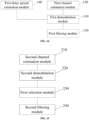
- the first channel estimation apparatus for a linear frequency modulation communications system further includes a first filtering module, configured to: before the first demodulation module demodulates preceding and next data symbols of a next pilot symbol in advance according to a channel estimate of a current pilot symbol, to obtain content of the preceding and next data symbols of the next pilot symbol, filter the channel estimate of the current pilot symbol.
- a first filtering module configured to: before the first demodulation module demodulates preceding and next data symbols of a next pilot symbol in advance according to a channel estimate of a current pilot symbol, to obtain content of the preceding and next data symbols of the next pilot symbol, filter the channel estimate of the current pilot symbol.
- the start location of the next pilot symbol is adjusted according to the content of the next pilot symbol, the content of the preceding and next data symbols, and the delay spread or the maximum path of the channel, and channel estimation is performed according to the adjusted start location. This can further improve accuracy of the channel estimate and effectively improve channel estimation performance and demodulation performance of a linear frequency modulation signal.
- the first channel estimation module is specifically configured to: when the delay spread or the maximum path is less than a preset threshold, if the content of the next data symbol of the next pilot symbol is the same as the content of the next pilot symbol, adjust the start location of the next pilot symbol to a second location, and perform channel estimation on the next pilot symbol at the second location, to obtain the channel estimate of the next pilot symbol; otherwise, adjust the start location of the next pilot symbol to a first location, and perform channel estimation on the next pilot symbol at the first location, to obtain the channel estimate of the next pilot symbol, where the first location is ahead of the second location; or when the delay spread or the maximum path is equal to or greater than the preset threshold, if the content of the preceding data symbol of the next pilot symbol is the same as the content of the next pilot symbol, adjust the start location of the next pilot symbol to the first location, and perform channel estimation on the next pilot symbol at the first location, to obtain the channel estimate of the next pilot symbol; otherwise, adjust the start location of the next pilot symbol to the second location, and perform
- the first channel estimation module is specifically configured to: perform channel estimation on the next pilot symbol at the start location in any of an FFT channel estimation manner, a matched filtering channel estimation manner, an LS channel estimation manner and an MMSE channel estimation manner, to obtain the channel estimate of the next pilot symbol.
- the second channel estimation apparatus for a linear frequency modulation communications system further includes: a first filtering module, configured to: before the first demodulation module demodulates preceding and next data symbols of a next pilot symbol in advance according to a channel estimate of a current pilot symbol, to obtain content of the preceding and next data symbols of the next pilot symbol, filter the channel estimate of the current pilot symbol.
- a first filtering module configured to: before the first demodulation module demodulates preceding and next data symbols of a next pilot symbol in advance according to a channel estimate of a current pilot symbol, to obtain content of the preceding and next data symbols of the next pilot symbol, filter the channel estimate of the current pilot symbol.
- a third channel estimation apparatus for a linear frequency modulation communications system including: a second channel estimation module, configured to perform channel estimation on each pilot symbol in a first channel estimation manner and a second channel estimation manner, to obtain a first channel estimate and a second channel estimate, where the first channel estimation manner includes either of an LS channel estimation manner and an MMSE channel estimation manner, and the second channel estimation manner includes a matched filtering channel estimation manner; a second demodulation module, configured to demodulate preceding and next data symbols of a next pilot symbol in advance according to a channel estimate of a current pilot symbol, to obtain content of the preceding and next data symbols of the next pilot symbol; and a first selection module, configured to select a channel estimate of the next pilot symbol from the first channel estimate and the second channel estimate according to the content of the preceding and next data symbols of the next pilot symbol, to obtain a channel estimate of each pilot symbol.
- a suitable channel estimate is selected from a plurality of channel estimates according to content of the next pilot symbol and the content of the preceding and next data symbols, so that accuracy of the channel estimate is improved. In this way, channel estimation performance and demodulation performance of a linear frequency modulation signal are effectively improved.
- the first selection module is specifically configured to: select the first channel estimate as the channel estimate of the next pilot symbol if the content of the next data symbol of the next pilot symbol is different from content of the next pilot symbol; otherwise, select the second channel estimate as the channel estimate of the next pilot symbol.
- the first selection module is further configured to: when the current pilot symbol is the first pilot symbol, regard the second channel estimate as the channel estimate of the first pilot symbol by default.
- the third channel estimation apparatus for a linear frequency modulation communications system further includes a second filtering module, configured to: before the second demodulation module uses the selected channel estimate of the next pilot symbol as the channel estimate of the current pilot symbol to demodulate in advance the preceding and next data symbols of the next pilot symbol, filter the selected channel estimate of the next pilot symbol.
- a fourth channel estimation apparatus for a linear frequency modulation communications system including: a third channel estimation module, configured to perform channel estimation on each pilot symbol in a first channel estimation manner and a second channel estimation manner, to obtain a first channel estimate and a second channel estimate, where the first channel estimation manner is an FFT channel estimation manner, and the second channel estimation manner is a matched filtering channel estimation manner; a third demodulation module, configured to demodulate preceding and next data symbols of a next pilot symbol in advance according to a channel estimate of a current pilot symbol, to obtain content of the preceding and next data symbols of the next pilot symbol; a third delay spread estimation module, configured to estimate a delay spread or a maximum path of a channel; and a second selection module, configured to select a channel estimate of the next pilot symbol from the first channel estimate and the second channel estimate according to the content of the preceding and next data symbols of the next pilot symbol and the delay spread or the maximum path, to obtain a channel estimate of each pilot symbol.
- a third channel estimation module configured to perform channel estimation
- a suitable channel estimate is selected from a plurality of channel estimates according to content of the next pilot symbol, the content of the preceding and next data symbols of the next pilot symbol, and the delay spread or the maximum path, so that accuracy of the channel estimate is improved. In this way, channel estimation performance and demodulation performance of a linear frequency modulation signal are effectively improved.
- the second selection module is specifically configured to: when the delay spread or the maximum path is equal to or greater than a preset threshold, if the content of the preceding data symbol of the next pilot symbol is the same as content of the next pilot symbol, select the first channel estimate as the channel estimate of the next pilot symbol; otherwise, select the second channel estimate as the channel estimate of the next pilot symbol; or when the delay spread or the maximum path is less than the preset threshold, if the content of the next data symbol of the next pilot symbol is the same as the content of the next pilot symbol, select the second channel estimate as the channel estimate of the next pilot symbol; otherwise, select the first channel estimate as the channel estimate of the next pilot symbol.
- the second selection module is further configured to: when the current pilot symbol is the first pilot symbol, regard the second channel estimate as the channel estimate of the first pilot symbol by default.
- the fourth channel estimation apparatus for a linear frequency modulation communications system further includes a third filtering module, configured to: before the third demodulation module uses the selected channel estimate of the next pilot symbol as the channel estimate of the current pilot symbol to demodulate in advance the preceding and next data symbols of the next pilot symbol, filter the selected channel estimate of the next pilot symbol.
- a third filtering module configured to: before the third demodulation module uses the selected channel estimate of the next pilot symbol as the channel estimate of the current pilot symbol to demodulate in advance the preceding and next data symbols of the next pilot symbol, filter the selected channel estimate of the next pilot symbol.
- a fifth channel estimation apparatus for a linear frequency modulation communications system including: a second channel estimation module, configured to perform channel estimation on each pilot symbol in a first channel estimation manner and a second channel estimation manner, to obtain a first channel estimate and a second channel estimate, where the first channel estimation manner includes either of an LS channel estimation manner and an MMSE channel estimation manner, and the second channel estimation manner includes a matched filtering channel estimation manner; a second demodulation module, configured to demodulate preceding and next data symbols of a next pilot symbol in advance according to a channel estimate of a current pilot symbol, to obtain content of the preceding and next data symbols of the next pilot symbol; a second delay spread estimation module, configured to estimate a delay spread or a maximum path of a channel; and a first selection module, configured to select a channel estimate of the next pilot symbol from the first channel estimate and the second channel estimate according to the content of the preceding and next data symbols of the next pilot symbol and the delay spread or the maximum path, to obtain a channel estimate of
- a suitable channel estimate is selected from a plurality of channel estimates according to content of the next pilot symbol, the content of the preceding and next data symbols, and the delay spread or the maximum path of the channel. This can further improve accuracy of the channel estimate and effectively improve channel estimation performance and demodulation performance of a linear frequency modulation signal.
- the first selection module is specifically configured to: when the delay spread or the maximum path is equal to or greater than a preset threshold, if the content of the preceding data symbol of the next pilot symbol is the same as content of the next pilot symbol, select the first channel estimate as the channel estimate of the next pilot symbol; otherwise, select the second channel estimate as the channel estimate of the next pilot symbol; or when the delay spread or the maximum path is less than the preset threshold, if the content of the next data symbol of the next pilot symbol is the same as the content of the next pilot symbol, select the second channel estimate as the channel estimate of the next pilot symbol; otherwise, select the first channel estimate as the channel estimate of the next pilot symbol.
- the first selection module is further configured to: when the current pilot symbol is the first pilot symbol, regard the second channel estimate as the channel estimate of the first pilot symbol by default.
- the fifth channel estimation apparatus for a linear frequency modulation communications system further includes a second filtering module, configured to: before the second demodulation module uses the selected channel estimate of the next pilot symbol as the channel estimate of the current pilot symbol to demodulate in advance the preceding and next data symbols of the next pilot symbol, filter the selected channel estimate of the next pilot symbol.
- the first delay spread estimation module, the second delay spread estimation module and the third delay spread estimation module may use a same manner to estimate a delay spread or a maximum path of the channel.
- the modules are specifically configured to: obtain a first delay spread or a first maximum path according to a synchronous signal; obtain a second delay spread or a second maximum path according to the pilot symbol; and estimate the delay spread of the channel according to at least one of the first delay spread and the second delay spread, or estimate the maximum path of the channel according to at least one of the first maximum path and the second maximum path.
- the first delay spread estimation module, the second delay spread estimation module and the third delay spread estimation module are specifically configured to: perform, if the synchronous signal is sent in an up chirp manner, pointwise multiplication on a received synchronous signal and a conjugate of the sent synchronous signal, and perform IFFT, to obtain a first power spectrum; or perform, if the synchronous signal is sent in a down chirp manner, pointwise multiplication on a received synchronous signal and a conjugate of the sent synchronous signal, and perform FFT, to obtain a second power spectrum; and obtain the first delay spread according to the first power spectrum or the second power spectrum through calculation, or obtain the first maximum path according to the first power spectrum or the second power spectrum through calculation.
- the first delay spread estimation module, the second delay spread estimation module and the third delay spread estimation module are specifically configured to: perform, if the pilot symbol is sent in an up chirp manner, pointwise multiplication on a received pilot symbol and a conjugate of the sent pilot symbol, and perform IFFT, to obtain a third power spectrum; or perform, if the pilot symbol is sent in a down chirp manner, pointwise multiplication on a received pilot symbol and a conjugate of the sent pilot symbol, and perform FFT, to obtain a fourth power spectrum; and obtain the second delay spread according to the third power spectrum or the fourth power spectrum through calculation, or obtain the second maximum path according to the third power spectrum or the fourth power spectrum through calculation.
- the first delay spread estimation module, the second delay spread estimation module and the third delay spread estimation module are specifically configured to: when estimating the delay spread of the channel according to at least one of the first delay spread and the second delay spread, filter the first delay spread to obtain the delay spread of the channel, or filter the second delay spread to obtain the delay spread of the channel, or perform weighting calculation on the filtered first delay spread and the filtered second delay spread, to obtain the delay spread of the channel.
- the first delay spread estimation module, the second delay spread estimation module and the third delay spread estimation module are specifically configured to: when estimating the maximum path of the channel according to at least one of the first maximum path and the second maximum path, filter the first maximum path to obtain the maximum path of the channel, or filter the second maximum path to obtain the maximum path of the channel, or perform weighting calculation on the filtered first maximum path and the filtered second maximum path, to obtain the maximum path of the channel.
- a linear frequency modulation communications system may include any of the first to the fifth channel estimation apparatuses for a linear frequency modulation communications system.
- the system can effectively ensure accuracy of a channel estimate and improve channel estimation performance and demodulation performance of a linear frequency modulation signal by any of the channel estimation apparatuses for a linear frequency modulation communications system.
- a computer-readable storage medium is provided.
- a channel estimation program for a linear frequency modulation communications system is stored in the computer-readable storage medium, and the channel estimation program is executed by a processor to achieve any of the first to the fifth channel estimation methods for a linear frequency modulation communications system.
- the storage medium can effectively ensure accuracy of a channel estimate and improve channel estimation performance and demodulation performance of a linear frequency modulation signal by performing any of the channel estimation methods for a linear frequency modulation communications system.
- a chip in some embodiments, includes a memory and a processor.
- a computer program is stored in the memory, and the computer program is executed by the processor to achieve any of the first to the fifth channel estimation methods for a linear frequency modulation communications system.
- the chip can effectively ensure accuracy of a channel estimate and improve channel estimation performance and demodulation performance of a linear frequency modulation signal by performing any of the channel estimation methods for a linear frequency modulation communications system.
- a pilot symbol may be sent at a certain interval when data symbols are sent.
- the pilot symbol and the data symbol may be sent in a manner shown in FIG. 1 . Every N symbols include one pilot symbol, and N is a positive integer that may be specifically 4, 8, 16 and the like.
- channel estimation on a pilot symbol may be affected by sending content of a preceding data symbol and a next data symbol. If sending content of preceding and next data symbols of a current pilot symbol is different from sending content of the pilot symbol, ISI may be caused, leading to an inaccurate channel estimate and decreased channel estimation performance.
- the impact of ISI is especially great for a multipath channel and a small spreading factor SF.
- this application provides a linear frequency modulation communications system and a channel estimation method and apparatus therefor, a medium, and a chip that can effectively ensure accuracy of a channel estimate and improve channel estimation performance and demodulation performance of a linear frequency modulation signal.
- the method is specifically: demodulating preceding and next data symbols of a next pilot symbol in advance according to a channel estimate of a current pilot symbol, to obtain content of the preceding and next data symbols of the next pilot symbol, and obtaining a channel estimate of the next pilot symbol according to content of the next pilot symbol and the content of the preceding and next data symbols of the next pilot symbol, thereby improving accuracy of the channel estimate and channel estimation performance; or demodulating preceding and next data symbols of a next pilot symbol in advance according to a channel estimate of a current pilot symbol, to obtain content of the preceding and next data symbols of the next pilot symbol, estimating a delay spread or a maximum path of a channel, and obtaining a channel estimate of the next pilot symbol according to content of the next pilot symbol, the content of the preceding and next data symbols of the next pilot symbol, and the delay spread or the maximum path of the channel, to further improve accuracy of the channel estimate and channel estimation performance.
- the channel estimation method for a linear frequency modulation communications system may include the following steps: Step S101. Demodulate preceding and next data symbols of a next pilot symbol in advance according to a channel estimate of a current pilot symbol, to obtain content of the preceding and next data symbols of the next pilot symbol.
- sending content of all symbols 1 to N+1 may be estimated according to a channel estimate of the pilot symbol 0, to obtain content of the pilot symbol N, the data symbol N-1 and the data symbol N+1 in advance through demodulation.
- sending content of all symbols N+2 to 2N+1 may be estimated according to a channel estimate of the pilot symbol N, to obtain content of the pilot symbol 2N, the data symbol 2N-1 and the data symbol 2N+1 in advance through demodulation.
- the rest can be deduced by analog.
- the method before the demodulating preceding and next data symbols of a next pilot symbol in advance according to a channel estimate of a current pilot symbol, to obtain content of the preceding and next data symbols of the next pilot symbol, the method further includes filtering the channel estimate of the current pilot symbol. That is, after the channel estimate of the current pilot symbol is obtained, the channel estimate of the current pilot symbol is filtered first, and then the preceding and next data symbols of the next pilot symbol is demodulated in advance according to the filtered channel estimate of the current pilot symbol, to obtain the content of the preceding and next data symbols of the next pilot symbol. In this way, the channel estimation performance and the demodulation performance are further improved.
- the channel estimate may be filtered by an existing technology, and filtering methods are not listed one by one herein. It should be noted that, when the pilot symbol is the first pilot symbol, the pilot symbol may be used as a channel estimate of the first pilot symbol and does not need to be filtered.
- Step S 102 Adjust a start location of the next pilot symbol according to content of the next pilot symbol and the content of the preceding and next data symbols of the next pilot symbol, and perform channel estimation on the next pilot symbol at the start location, to obtain a channel estimate of the next pilot symbol.
- the adjusting a start location of the next pilot symbol according to content of the next pilot symbol and the content of the preceding and next data symbols of the next pilot symbol, and performing channel estimation on the next pilot symbol at the start location, to obtain a channel estimate of the next pilot symbol includes: if the content of the next data symbol of the next pilot symbol is different from the content of the next pilot symbol, adjusting the start location of the next pilot symbol to a first location, and performing channel estimation on the next pilot symbol at the first location, to obtain the channel estimate of the next pilot symbol; otherwise, adjusting the start location of the next pilot symbol to a second location, and performing channel estimation on the next pilot symbol at the second location, to obtain the channel estimate of the next pilot symbol, where the first location is ahead of the second location.
- the current pilot symbol is the first pilot symbol, for example, the pilot symbol 0 shown in FIG. 1
- content of the pilot symbol N, the data symbol N-1 and the data symbol N+1 may be estimated according to a channel estimate of the pilot symbol 0. If the content of the next data symbol N+1 of the pilot symbol N is different from the content of the pilot symbol N, a start location of the pilot symbol N may be adjusted to the first location, and channel estimation is performed on the pilot symbol N at the first location, to obtain a channel estimate of the pilot symbol N; otherwise, the start location of the pilot symbol N is adjusted to the second location, and channel estimation is performed on the pilot symbol N at the second location, to obtain the channel estimate of the pilot symbol N.
- the pilot symbol is not the first pilot symbol, for example, is the pilot symbol N shown in FIG. 1
- content of the pilot symbol 2N, the data symbol 2N-1 and the data symbol 2N+1 may be estimated according to the channel estimate of the pilot symbol N. If the content of the next data symbol 2N+1 of the pilot symbol 2N is different from the content of the pilot symbol 2N, a start location of the pilot symbol 2N may be adjusted to the first location, and channel estimation is performed on the pilot symbol 2N at the first location, to obtain a channel estimate of the pilot symbol 2N; otherwise, the start location of the pilot symbol 2N is adjusted to the second location, and channel estimation is performed on the pilot symbol 2N at the second location, to obtain the channel estimate of the pilot symbol 2N.
- the channel estimate of each pilot symbol can be obtained by analog.
- channel estimation may be performed by adjusting the start location of the pilot symbol according to the content of the pilot symbol and the content of the preceding and next data symbols of the pilot symbol, as shown in Table 1, to obtain the channel estimate of each pilot symbol.
- Table 1 Seque nce A relationship between the content of a pilot symbol and the content of a preceding data symbol of the pilot symbol A relationship between the content of a pilot symbol and the content of a next data symbol of the pilot symbol A start location of channel estimation on a pilot symbol 1 Same Same Second location or first location 2 Same Different First location 3 Different Same Second location 4 Different Different First location
- time offset may be moved forward, that is, to adjust the start location of the pilot symbol to the first location, so that no ISI exists during channel estimation.
- time offset may be moved backward, that is, to adjust the start location of the pilot symbol to the second location, so that no ISI exists during channel estimation.
- time offset may be moved forward, that is, to adjust the start location of the pilot symbol to the first location, so that ISI during channel estimation is significantly reduced.
- the start location of the pilot symbol may be adjusted to the first location or the second location, and there is little difference between accuracy of obtained channel estimates.
- channel estimation may be performed on the next pilot symbol at the start location in any of an FFT channel estimation manner, a matched filtering channel estimation manner, an LS channel estimation manner and an MMSE channel estimation manner, to obtain the channel estimate of the next pilot symbol. That is, when channel estimation is performed by adjusting a start location of a pilot symbol, any of the FFT channel estimation manner, the matched filtering channel estimation manner, the LS channel estimation manner and the MMSE channel estimation manner may be used to perform channel estimation on the pilot symbol, to obtain a channel estimate.
- an estimation manner shown in FIG. 3 may be used. That is, convolution operation is performed on a received pilot symbol and a matched filter, to obtain a matched filtering channel estimate of the pilot symbol.
- the matched filter is a conjugate of a sent pilot symbol, that is, a conjugate of an up-chirp signal.
- an estimation manner shown in FIG. 4 may be used. That is, a received pilot symbol is multiplied by a conjugate of a sent pilot symbol first, and then inverse fast Fourier transform (IFFT) is performed, and next a transformation result is multiplied by a rotation phase, to obtain an FFT channel estimate of the pilot symbol.
- the rotation phase may be obtained according to an initial phase of the pilot symbol and a multipath index, and may be specifically obtained by the formula e j ⁇ 2 ⁇ n 2 ⁇ 2 Kn 2 SF + 1 through calculation.
- K represents an index corresponding to the initial phase of the pilot symbol, that is, an initial phase of a chirp signal
- n represents a multipath index
- SF represents a spreading factor.
- R represents an LS channel estimate.
- H represents an ideal channel estimate.
- A represents a matrix formed by sent signals, for example, a matrix formed by transmitted chirp signals.
- A s 0 s 1 ⁇ s N ⁇ 1 s N ⁇ 1 s 0 ⁇ s N ⁇ 2 ⁇ ⁇ ⁇ ⁇ s 1 s 2 ⁇ s 0 .
- the MMSE channel estimate H ⁇ A T A + ⁇ 2 ⁇ 1 (AR) may be derived from the formula (2). Description of R and A is the same as that in the LS channel estimation, and ⁇ represents noise power.
- the start location of the next pilot symbol is adjusted according to the content of the next pilot symbol and the content of the preceding and next data symbols, and channel estimation is performed according to the adjusted start location, so that accuracy of the channel estimate can be effectively improved. In this way, channel estimation performance and demodulation performance of a linear frequency modulation signal can be effectively improved.
- the channel estimation method for a linear frequency modulation communications system may include the following steps: Step S201. Demodulate preceding and next data symbols of a next pilot symbol in advance according to a channel estimate of a current pilot symbol, to obtain content of the preceding and next data symbols of the next pilot symbol, and estimate a delay spread or a maximum path of a channel.
- step S201 for description of the demodulating preceding and next data symbols of a next pilot symbol in advance according to a channel estimate of a current pilot symbol, to obtain content of the preceding and next data symbols of the next pilot symbol in step S201, please refer to relevant description in step S101, and details are not described herein again.
- the method further includes filtering the channel estimate of the current pilot symbol. Please refer to relevant description instep S101, and details are not described herein again.
- estimation of a delay spread or a maximum path of the channel is mainly described herein. It should be noted that, estimation of a delay spread or a maximum path may be performed at an interval of a preset number (for example, 1, 2 and the like) of pilot symbols.
- the estimating a delay spread of a channel may include: Step S301. Obtain a first delay spread according to a synchronous signal.
- the synchronous signal refers to that a plurality of signal sources are given by a same carrier at one time, to provide machines that need to deal with information synchronously with signals to be referred to at a same time, so that receivers can receive more or better information.
- the synchronous signal is located ahead of the pilot symbol 0 shown in FIG. 1 , and there is usually more than one symbol.
- the obtaining a first delay spread according to a synchronous signal includes: performing, if the synchronous signal is sent in an up chirp manner, pointwise multiplication on a received synchronous signal and a conjugate of the sent synchronous signal, and performing IFFT, to obtain a first power spectrum; or performing, if the synchronous signal is sent in a down chirp manner, pointwise multiplication on a received synchronous signal and a conjugate of the sent synchronous signal, and performing FFT, to obtain a second power spectrum; and obtaining the first delay spread according to the first power spectrum or the second power spectrum through calculation.
- the first delay spread Trms1 may be obtained in different calculation manners according to different sending manners of the synchronous signal.
- the synchronous signal is sent in an up chirp manner, pointwise multiplication is performed on a received synchronous signal and a conjugate of the sent synchronous signal, and IFFT is performed, to obtain a square of each sampling point, and then obtain the first power spectrum. Then, the first power spectrum is substituted into the formula (3) to obtain the first delay spread Trms1.
- pointwise multiplication is performed on a received synchronous signal and a conjugate of the sent synchronous signal, and FFT is performed, to obtain a square of each sampling point, and then obtain the second power spectrum.
- T rms 1 ⁇ l L ⁇ 1 P l ⁇ l 2 ⁇ l L ⁇ 1 P l ⁇ ⁇ l L ⁇ 1 P l ⁇ l ⁇ l L ⁇ 1 P l 2 P l is power of a 1 st path in the power spectrum, and ⁇ l is a delay of the 1 st path in the power spectrum.
- Step S302. Obtain a second delay spread according to the pilot symbol.
- the obtaining a second delay spread according to the pilot symbol includes: performing, if the pilot symbol is sent in an up chirp manner, pointwise multiplication on a received pilot symbol and a conjugate of the sent pilot symbol, and performing IFFT, to obtain a third power spectrum; or performing, if the pilot symbol is sent in a down chirp manner, pointwise multiplication on a received pilot symbol and a conjugate of the sent pilot symbol, and performing FFT, to obtain a fourth power spectrum; and obtaining the second delay spread according to the third power spectrum or the fourth power spectrum through calculation.
- the second delay spread Trms2 may be obtained in different calculation manners according to different sending manners of the pilot symbol.
- the pilot symbol is sent in an up chirp manner
- pointwise multiplication is performed on a received pilot symbol and a conjugate of the sent pilot symbol, and IFFT is performed, to obtain a square of each sampling point, and then obtain the third power spectrum.
- the third power spectrum is substituted into the formula (4) to obtain the second delay spread Trms2.
- pointwise multiplication is performed on a received pilot symbol and a conjugate of the sent pilot symbol, and FFT is performed, to obtain a square of each sampling point, and then obtain the fourth power spectrum.
- T rms 2 ⁇ m M ⁇ 1 P m ⁇ m 2 ⁇ m M ⁇ 1 P m ⁇ ⁇ m M ⁇ 1 P m ⁇ m ⁇ m M ⁇ 1 P m 2 P m is power of an m th path in the power spectrum, and ⁇ m is a delay of the m th path in the power spectrum.
- Step S303 Estimate the delay spread of the channel according to at least one of the first delay spread and the second delay spread.
- the delay spread of the channel may be estimated according to the first delay spread, or the delay spread of the channel may be estimated according to the second delay spread, or the delay spread of the channel may be estimated according to the first delay spread and the second delay spread.
- the estimating the delay spread of the channel according to at least one of the first delay spread and the second delay spread includes: filtering the first delay spread to obtain the delay spread of the channel, or filtering the second delay spread to obtain the delay spread of the channel, or performing weighting calculation on the filtered first delay spread and the filtered second delay spread, to obtain the delay spread of the channel.
- a value T rms 1 ' obtained after the first delay spread is filtered may be used as the delay spread of the channel; or a value T rms 2 ' obtained after the second delay spread is filtered may be used as the delay spread of the channel; or weighted summation is performed on the value T rms 1 ' obtained after the first delay spread is filtered and the value T rms 2 ' obtained after the second delay spread is filtered, and then an obtained value is used as the delay spread of the channel.
- a weight corresponding to the first delay spread may be set as ⁇
- a weight corresponding to the second delay spread may be set to 1- ⁇
- the delay spread of the channel is obtained through calculation according to the value T rms 1 ' obtained after the first delay spread is filtered, the weight ⁇ corresponding to the first delay spread, the value T rms 2 ' obtained after the second delay spread is filtered, and the weight 1- ⁇ corresponding to the second delay spread.
- T rms T rms 1 ′ ⁇ ⁇ + T rms 2 ′ ⁇ 1 ⁇ ⁇
- a relatively accurate delay spread of the channel may be obtained according to the first delay spread obtained according to the synchronous signal and/or according to the second delay spread obtained according to the pilot symbol, thereby further improving channel estimation accuracy.
- the estimating a maximum path of a channel may include: Step S401. Obtain a first maximum path according to a synchronous signal.
- the obtaining a first maximum path according to a synchronous signal includes: performing, if the synchronous signal is sent in an up chirp manner, pointwise multiplication on a received synchronous signal and a conjugate of the sent synchronous signal, and performing IFFT, to obtain a first power spectrum; or performing, if the synchronous signal is sent in a down chirp manner, pointwise multiplication on a received synchronous signal and a conjugate of the sent synchronous signal, and performing FFT, to obtain a second power spectrum; and obtaining the first maximum path according to the first power spectrum or the second power spectrum through calculation.
- the first maximum pathTmax1 may be obtained in different calculation manners according to different sending manners of the synchronous signal.
- the synchronous signal is sent in an up chirp manner, pointwise multiplication is performed on a received synchronous signal and a conjugate of the sent synchronous signal, and IFFT is performed, to obtain a square of each sampling point, and then obtain the first power spectrum.
- the first maximum pathTmax1 is obtained according to the first power spectrum.
- pointwise multiplication is performed on a received synchronous signal and a conjugate of the sent synchronous signal, and FFT is performed, to obtain a square of each sampling point, and then obtain the second power spectrum.
- the first maximum pathTmax1 is obtained according to the second power spectrum. This is specifically as follows: obtaining maximum path power MaxPower and Noise (an average of power of some sampling points in the power spectrum, and a location of each sampling point may be set according to a supported maximum delay) in the power spectrum, and selecting a path greater than max (MaxPower*Threshold 1, Noise*Threshold2).
- the maximum path is marked as Tmax1, and Threshold1 and Threshold2 are respectively a maximum path threshold and a noise threshold that may be set according to an actual requirement.
- Step S402. Obtain a second maximum path according to the pilot symbol.
- the obtaining a second maximum path according to the pilot symbol includes: performing, if the pilot symbol is sent in an up chirp manner, pointwise multiplication on a received pilot symbol and a conjugate of the sent pilot symbol, and performing IFFT, to obtain a third power spectrum; or performing, if the pilot symbol is sent in a down chirp manner, pointwise multiplication on a received pilot symbol and a conjugate of the sent pilot symbol, and performing FFT, to obtain a fourth power spectrum; and obtaining the second maximum path according to the third power spectrum or the fourth power spectrum through calculation.
- the second maximum pathTmax2 may be obtained in different calculation manners according to different sending manners of the pilot symbol.
- the pilot symbol is sent in an up chirp manner, pointwise multiplication is performed on a received pilot symbol and a conjugate of the sent pilot symbol, and IFFT is performed, to obtain a square of each sampling point, and then obtain the third power spectrum.
- the second maximum pathTmax2 is obtained according to the third power spectrum.
- pointwise multiplication is performed on a received pilot symbol and a conjugate of the sent pilot symbol, and FFT is performed, to obtain a square of each sampling point, and then obtain the fourth power spectrum.
- the second maximum pathTmax2 is obtained according to the fourth power spectrum.
- This is specifically as follows: obtaining maximum path power MaxPower and Noise (an average of power of some sampling points in the power spectrum, and a location of each sampling point may be set according to a supported maximum delay) in the power spectrum, and selecting a path greater than max (MaxPower ⁇ Threshold1, Noise ⁇ Threshold2).
- the mum path is marked as Tmax2, and Threshold1 and Threshold2 are respectively a maximum path threshold and a noise threshold that may be set according to an actual requirement.
- Step S403. Estimate the maximum path of a channel according to at least one of the first maximum path and the second maximum path.
- the maximum path of the channel may be estimated according to the first maximum path, or the maximum path of the channel may be estimated according to the second maximum path, or the maximum path of the channel may be estimated according to the first maximum path and the second maximum path.
- the estimating the maximum path of the channel according to at least one of the first maximum path and the second maximum path includes: filtering the first maximum path to obtain the maximum path of the channel, or filtering the second maximum path to obtain the maximum path of the channel, or performing weighting calculation on the filtered first maximum path and the filtered second maximum path, to obtain the maximum path of the channel.
- a specific obtaining process is the same as that in step S303, and details are not described herein again.
- a relatively accurate maximum path of the channel may be obtained according to the first maximum path obtained according to the synchronous signal and/or the second maximum path obtained according to the pilot symbol, thereby further improving channel estimation accuracy.
- Step S202 Adjust a start location of the next pilot symbol according to content of the next pilot symbol, the content of the preceding and next data symbols of the next pilot symbol, and the delay spread or the maximum path, and perform channel estimation on the next pilot symbol at the start location, to obtain a channel estimate of the next pilot symbol.
- the channel estimate of the next pilot symbol may be obtained according to the content of the next pilot symbol, the content of the preceding and next data symbols of the next pilot symbol, and the delay spread.
- the channel estimate of the next pilot symbol may be obtained according to the content of the next pilot symbol, the content of the preceding and next data symbols of the next pilot symbol, and the maximum path.
- either of the delay spread and the maximum path may be used.
- the adjusting a start location of the next pilot symbol according to content of the next pilot symbol, the content of the preceding and next data symbols of the next pilot symbol, and the delay spread or the maximum path, and performing channel estimation on the next pilot symbol at the start location, to obtain a channel estimate of the next pilot symbol includes: when the delay spread or the maximum path is less than a preset threshold, if the content of the next data symbol of the next pilot symbol is the same as the content of the next pilot symbol, adjusting the start location of the next pilot symbol to a second location, and performing channel estimation on the next pilot symbol at the second location, to obtain the channel estimate of the next pilot symbol; otherwise, adjusting the start location of the next pilot symbol to a first location, and performing channel estimation on the next pilot symbol at the first location, to obtain the channel estimate of the next pilot symbol, where the first location is ahead of the second location; or when the delay spread or the maximum path is equal to or greater than the preset threshold, if the content of the preceding data symbol of the next pilot symbol is
- the current pilot symbol is the first pilot symbol, for example, the pilot symbol 0 shown in FIG. 1
- a delay spread (or maximum path) obtained at the pilot symbol N is less than the preset threshold, for example, 0.25 ⁇ s
- a start location of the pilot symbol N is adjusted to the second location, and channel estimation is performed on the pilot symbol N at the second location, to obtain a channel estimate of the pilot symbol N.
- the start location of the pilot symbol N is adjusted to the first location, and channel estimation is performed on the pilot symbol N at the first location, to obtain the channel estimate of the pilot symbol N.
- the delay spread (or the maximum path) obtained at the pilot symbol N is equal to or greater than the preset threshold, for example, 0.25 ⁇ s
- the start location of the pilot symbol N is adjusted to the first location, and channel estimation is performed on the pilot symbol N at the first location, to obtain the channel estimate of the pilot symbol N.
- the start location of the pilot symbol N is adjusted to the second location, and channel estimation is performed on t the pilot symbol N at the second location, to obtain the channel estimate of the pilot symbol N.
- the pilot symbol is not the first pilot symbol, for example, is the pilot symbol N shown in FIG. 1
- a delay spread (or maximum path) obtained at the pilot symbol 2N is less than the preset threshold, for example, 0.25 ⁇ s
- a start location of the pilot symbol 2N is adjusted to the second location, and channel estimation is performed on the pilot symbol 2N at the second location, to obtain a channel estimate of the pilot symbol 2N.
- the start location of the pilot symbol 2N is adjusted to the first location, and channel estimation is performed on the pilot symbol 2N at the first location, to obtain the channel estimate of the pilot symbol 2N.
- the delay spread (or the maximum path) obtained at the pilot symbol 2N is equal to or greater than the preset threshold, for example, 0.25 ⁇ s
- the start location of the pilot symbol 2N is adjusted to the first location, and channel estimation is performed on the pilot symbol 2N at the first location, to obtain the channel estimate of the pilot symbol 2N.
- the start location of the pilot symbol 2N is adjusted to the second location, and channel estimation is performed on the pilot symbol 2N at the second location, to obtain the channel estimate of the pilot symbol 2N.
- the channel estimate of each pilot symbol can be obtained by analog.
- channel estimation may be performed by adjusting the start location of the pilot symbol according to the content of the pilot symbol, the content of the preceding and next data symbols of the pilot symbol, and the delay spread or the maximum path, as shown in Table 2, to obtain the channel estimate of each pilot symbol.
- channel estimation may be performed on the next pilot symbol at the start location in any of an FFT channel estimation manner, a matched filtering channel estimation manner, an LS channel estimation manner and an MMSE channel estimation manner, to obtain the channel estimate of the next pilot symbol. That is, when channel estimation is performed by adjusting a start location of a pilot symbol, any of the FFT channel estimation manner, the matched filtering channel estimation manner, the LS channel estimation manner and the MMSE channel estimation manner may be used to perform channel estimation on the pilot symbol, to obtain a channel estimate.
- the start location of the next pilot symbol is adjusted according to the content of the next pilot symbol, the content of the preceding and next data symbols, and the delay spread or the maximum path of the channel, and channel estimation is performed according to the adjusted start location. This can further improve accuracy of the channel estimate and effectively improve channel estimation performance and demodulation performance of a linear frequency modulation signal.
- the channel estimation method for a linear frequency modulation communications system may include the following steps: Step S501. Perform channel estimation on each pilot symbol in a first channel estimation manner and a second channel estimation manner, to obtain a first channel estimate and a second channel estimate.
- the first channel estimation manner includes any of an FFT channel estimation manner, an LS channel estimation manner, and an MMSE channel estimation manner
- the second channel estimation manner includes a matched filtering channel estimation manner.
- channel estimation may be performed on the pilot symbol 0, the pilot symbol N, the pilot symbol 2N and the like shown in FIG. 1 in the first channel estimation manner (for example, the FFT channel estimation manner, the LS channel estimation manner, or the MMSE channel estimation manner), to obtain a first channel estimate of each pilot symbol (for example, an FFT channel estimate, an LS channel estimate or an MMSE channel estimate).
- channel estimation may be performed on the pilot symbol 0, the pilot symbol N, the pilot symbol 2N and the like shown in FIG. 1 in the second channel estimation manner (for example, the matched filtering channel estimation manner), to obtain a second channel estimate of each pilot symbol (for example, a matched filtering channel estimate). Description of the channel estimation manner is the same as above, and details are not described herein again.
- Step S502 Demodulate preceding and next data symbols of a next pilot symbol in advance according to a channel estimate of a current pilot symbol, to obtain content of the preceding and next data symbols of the next pilot symbol.
- sending content of all symbols 1 to N+1 may be estimated according to a channel estimate of the pilot symbol 0, to obtain content of the pilot symbol N, the data symbol N-1 and the data symbol N+1 in advance through demodulation.
- sending content of all symbols N+2 to 2N+1 may be estimated according to a channel estimate of the pilot symbol N, to obtain content of the pilot symbol 2N, the data symbol 2N-1 and the data symbol 2N+1 in advance through demodulation.
- the rest can be deduced by analog.
- the method before selecting the channel estimate of the next pilot symbol as the channel estimate of the current pilot symbol to demodulate in advance the preceding and next data symbols of the next pilot symbol, the method further includes filtering the selected channel estimate of the next pilot symbol. That is, after the channel estimate of the current pilot symbol is obtained, the channel estimate of the current pilot symbol is filtered first, and then the preceding and next data symbols of the next pilot symbol is demodulated in advance according to the filtered channel estimate of the current pilot symbol, to obtain the content of the preceding and next data symbols of the next pilot symbol. In this way, the channel estimation performance and the demodulation performance are further improved.
- Step S503 Select a channel estimate of the next pilot symbol from the first channel estimate and the second channel estimate according to the content of the preceding and next data symbols of the next pilot symbol, to obtain a channel estimate of each pilot symbol.
- a more suitable channel estimate may be selected from the first channel estimate and the second channel estimate according to the content of the next pilot symbol and the content of the preceding and next data symbols of the next pilot symbol and used as the channel estimate of the next pilot symbol, to improve accuracy of the channel estimate, and improve channel estimation performance and demodulation performance of a linear frequency modulation signal.
- the channel estimate of the pilot symbol N may be determined from the first channel estimate (for example, the FFT channel estimate, the LS channel estimate or the MMSE channel estimate) and the second channel estimate (for example, the matched filtering channel estimate) of the pilot symbol N according to the content of the pilot symbol N, the data symbol N-1 and the data symbol N+1.
- the pilot symbol is not the first pilot symbol, for example, is the pilot symbol N shown in FIG.
- the channel estimate of the pilot symbol 2N may be determined from the first channel estimate (for example, the FFT channel estimate, the LS channel estimate or the MMSE channel estimate) and the second channel estimate (for example, the matched filtering channel estimate) of the pilot symbol 2N according to the content of the pilot symbol 2N, the data symbol 2N-1 and the data symbol 2N+1.
- the rest can be deduced by analog, until a channel estimate of each pilot symbol is obtained.
- the selecting a channel estimate of the next pilot symbol from the first channel estimate and the second channel estimate according to the content of the preceding and next data symbols of the next pilot symbol includes: selecting the first channel estimate as the channel estimate of the next pilot symbol if the content of the next data symbol of the next pilot symbol is different from content of the next pilot symbol; otherwise, selecting the second channel estimate as the channel estimate of the next pilot symbol.
- the channel estimate of the pilot symbol N is an estimate obtained by performing channel estimation in the first channel estimation manner, that is, the first channel estimate (for example, the FFT channel estimate, the LS channel estimate or the MMSE channel estimate). Otherwise, the channel estimate of the pilot symbol N is an estimate obtained by performing channel estimation in the second channel estimation manner, that is, the second channel estimate (for example, the matched filtering channel estimate).
- the pilot symbol is not the first pilot symbol, for example, is the pilot symbol N shown in FIG. 1
- content of the pilot symbol 2N, the data symbol 2N-1 and the data symbol 2N+1 may be estimated according to the channel estimate of the pilot symbol N.
- the channel estimate of the pilot symbol 2N is an estimate obtained by performing channel estimation in the first channel estimation manner, that is, the first channel estimate (for example, the FFT channel estimate, the LS channel estimate or the MMSE channel estimate).
- the channel estimate of the pilot symbol 2N is an estimate obtained by performing channel estimation in the second channel estimation manner, that is, the second channel estimate (for example, the matched filtering channel estimate).
- the channel estimate of each pilot symbol can be obtained by analog.
- channel estimation may be performed in any of the manners in Table 3 according to the content of the pilot symbol and the content of the preceding and next data symbols of the pilot symbol, to obtain the channel estimate of each pilot symbol.
- Table 3 Sequence A relationship between content of a pilot symbol and content of a preceding data symbol of the pilot symbol A relationship between content of a pilot symbol and content of a next data symbol of the pilot symbol A channel estimation manner of a pilot symbol 1 Same Same Second channel estimation manner or first channel estimation manner 2 Same Different First channel estimation manner 3 Different Same Second channel estimation manner 4 Different Different First channel estimation manner
- the first channel estimation manner is an FFT channel estimation manner, an LS channel estimation manner or an MMSE channel estimation manner, and the second channel estimation manner is a matched filtering channel estimation manner.
- the second channel estimate (for example, the matched filtering channel estimate) may be regarded as a channel estimate of the first pilot symbol by default.
- the channel estimate of the pilot symbol may be obtained in the first channel estimation manner or the second channel estimation manner, and there is little difference between accuracy of obtained channel estimates.
- the channel estimation method for a linear frequency modulation communications system may include:
- the channel estimate H ⁇ F_iN of the pilot symbol iN is determined according to Table 3.
- Step S604. Filter the determined channel estimate H ⁇ F_iN of the pilot symbol iN, to obtain a channel estimate H ⁇ FF_iN of the pilot symbol iN.
- Step S605. Estimate sending content of all symbols iN+2 to (i+1)N+1 by the channel estimate H ⁇ FF_iN of the pilot symbol iN obtained through filtering, and return to step S603, until the channel estimate of each pilot symbol and sending content of each data symbol are obtained.
- a pilot symbol is usually a known symbol during channel estimation. Therefore, when received data symbols are demodulated or estimated, the pilot symbol may not be demodulated or estimated. Instead, the known pilot symbol may directly be used. Hence, the pilot symbol may also be demodulated or estimated to ensure accuracy of the pilot symbol, thereby ensuring channel estimation accuracy and improving channel estimation performance.
- the first channel estimation manner is the FFT channel estimation manner and the second channel estimation manner is the matched filtering channel estimation manner is used theoretically blow to show the effects of the foregoing embodiments.
- the estimation manner shown in FIG. 3 may be used. That is, convolution operation is performed on a received pilot symbol and a matched filter, to obtain a matched filtering channel estimate of the pilot symbol, which may be marked as H ⁇ MF .
- the matched filter is a conjugate of a sent pilot symbol, that is, a conjugate of an up-chirp signal.
- R X MF _ ideal + X MF _ 1 + X MF _ 2 ⁇ X MF _ 3 ⁇ X MF _ 4 H + W X MF_ ideal , X MF_1 , X MF_2 , X MF_3 , and X MF_4 are as follows:
- X MF_ ideal S L 1 m ... S 1 m S 0 m S N ⁇ 1 m ... S N ⁇ L 2 + 1 m S L 1 + 1 m ... S 2 m S 1 m 0 ... S N ⁇ L 2 + 2 m ... ... ... ... ... ... ... ... ... ... S L 1 m ... S 0 m 0 ... S N ⁇ L 2 + 1 m ... S 1 0 m 0 ... S N ⁇ L 2 + 2 m ... ... ... ... ... ... ... ... ... ... S L 1
- the estimation manner shown in FIG. 4 may be used. That is, a received pilot symbol is multiplied by a conjugate of a sent pilot symbol first, and then IFFT is performed, and then a transformation result is multiplied by a rotation phase, to obtain an FFT channel estimate of the pilot symbol, which may be marked as ⁇ FFT .
- the rotation phase may be obtained according to an initial phase of the pilot symbol and a multipath index, and may be specifically obtained by the formula e j ⁇ 2 ⁇ n 2 ⁇ 2 Kn 2 SF + 1 through calculation.
- K represents an index corresponding to the initial phase of the pilot symbol, that is, an initial phase of a chirp signal
- n a multipath index
- IFFTW represents an IFFT matrix.
- channel estimation is performed in any of the manners in Table 3 according to the content of the pilot symbol and the content of the preceding and next data symbols of the pilot symbol, so that the obtained channel estimate of each pilot symbol is good. This can ensure accuracy of the channel estimate and improve channel estimation performance and demodulation performance of a linear frequency modulation signal.
- a suitable channel estimate is selected from a plurality of channel estimates according to content of the next pilot symbol and the content of the preceding and next data symbols, so that accuracy of the channel estimate is improved. In this way, channel estimation performance and demodulation performance of a linear frequency modulation signal can be improved.
- the channel estimation method for a linear frequency modulation communications system may include the following steps:
- step S702 for the demodulating preceding and next data symbols of a next pilot symbol in advance according to a channel estimate of a current pilot symbol, to obtain content of the preceding and next data symbols of the next pilot symbol in step S702, please refer to relevant description in step S502, and details are not described herein again.
- the method further includes filtering the selected channel estimate of the next pilot symbol. Please refer to relevant description in step S502, and details are not described herein again.
- estimation of a delay spread or a maximum path of the channel is mainly described herein. It should be noted that, estimation of a delay spread or a maximum path may be performed at an interval of a preset number (for example, 1, 2 and the like) of pilot symbols.
- the estimating a delay spread or a maximum path of the channel includes: obtaining a first delay spread or a first maximum path according to a synchronous signal; obtaining a second delay spread or a second maximum path according to the pilot symbol; and estimating the delay spread of the channel according to at least one of the first delay spread and the second delay spread, or estimating the maximum path of the channel according to at least one of the first maximum path and the second maximum path.
- the obtaining a first delay spread or a first maximum path according to a synchronous signal includes: performing, if the synchronous signal is sent in an up chirp manner, pointwise multiplication on a received synchronous signal and a conjugate of the sent synchronous signal, and performing IFFT, to obtain a first power spectrum; or performing, if the synchronous signal is sent in a down chirp manner, pointwise multiplication on a received synchronous signal and a conjugate of the sent synchronous signal, and performing FFT, to obtain a second power spectrum; and obtaining the first delay spread according to the first power spectrum or the second power spectrum through calculation, or obtaining the first maximum path according to the first power spectrum or the second power spectrum through calculation.
- the obtaining a second delay spread or a second maximum path according to the pilot symbol includes: performing, if the pilot symbol is sent in an up chirp manner, pointwise multiplication on a received pilot symbol and a conjugate of the sent pilot symbol, and performing IFFT, to obtain a third power spectrum; or performing, if the pilot symbol is sent in a down chirp manner, pointwise multiplication on a received pilot symbol and a conjugate of the sent pilot symbol, and performing FFT, to obtain a fourth power spectrum; and obtaining the second delay spread according to the third power spectrum or the fourth power spectrum through calculation, or obtaining the second maximum path according to the third power spectrum or the fourth power spectrum through calculation.
- the estimating the delay spread of the channel according to at least one of the first delay spread and the second delay spread includes: filtering the first delay spread to obtain the delay spread of the channel, or filtering the second delay spread to obtain the delay spread of the channel, or performing weighting calculation on the filtered first delay spread and the filtered second delay spread, to obtain the delay spread of the channel.
- the estimating the maximum path of the channel according to at least one of the first maximum path and the second maximum path includes: filtering the first maximum path to obtain the maximum path of the channel, or filtering the second maximum path to obtain the maximum path of the channel, or performing weighting calculation on the filtered first maximum path and the filtered second maximum path, to obtain the maximum path of the channel.
- step S201 for the estimating a delay spread or a maximum path of the channel, please refer to relevant description in step S201, and details are not described herein again.
- Step S703. Select a channel estimate of the next pilot symbol from the first channel estimate and the second channel estimate according to the content of the preceding and next data symbols of the next pilot symbol and the delay spread or the maximum path, to obtain a channel estimate of each pilot symbol.
- the channel estimate of the next pilot symbol may be obtained according to the content of the next pilot symbol, the content of the preceding and next data symbols of the next pilot symbol, and the delay spread.
- the channel estimate of the next pilot symbol may be obtained according to the content of the next pilot symbol, the content of the preceding and next data symbols of the next pilot symbol, and the maximum path.
- either of the delay spread and the maximum path may be used.
- the channel estimate of the pilot symbol N may be determined from the first channel estimate (that is, the FFT channel estimate) and the second channel estimate (that is, the matched filtering channel estimate) according to the content of the pilot symbol N, the data symbol N-1 and the data symbol N+1, and the delay spread (or the maximum path) of the channel estimation obtained through estimation.
- the pilot symbol is not the first pilot symbol, for example, is the pilot symbol N shown in FIG.
- the channel estimate of the pilot symbol 2N may be determined from the first channel estimate (that is, the FFT channel estimate) and the second channel estimate (that is, the matched filtering channel estimate) according to the content of the pilot symbol 2N, the data symbol 2N-1 and the data symbol 2N+1, and the delay spread (or the maximum path) of the channel estimation obtained through estimation.
- the rest can be deduced by analog, until a channel estimate of each pilot symbol is obtained.
- the selecting a channel estimate of the next pilot symbol from the first channel estimate and the second channel estimate according to the content of the preceding and next data symbols of the next pilot symbol and the delay spread or the maximum path includes: when the delay spread or the maximum path is equal to or greater than a preset threshold, if the content of the preceding data symbol of the next pilot symbol is the same as content of the next pilot symbol, selecting the first channel estimate as the channel estimate of the next pilot symbol; otherwise, selecting the second channel estimate as the channel estimate of the next pilot symbol; or when the delay spread or the maximum path is less than the preset threshold, if the content of the next data symbol of the next pilot symbol is the same as the content of the next pilot symbol, selecting the second channel estimate as the channel estimate of the next pilot symbol; otherwise, selecting the first channel estimate as the channel estimate of the next pilot symbol.
- the channel estimate of the pilot symbol N is an estimate obtained by performing channel estimation in the second channel estimation manner, that is, the second channel estimate (that is, the matched filtering channel estimate); otherwise, the channel estimate of the pilot symbol N is an estimate obtained by performing channel estimation in the first channel estimation manner, that is, the first channel estimate (that is, the FFT channel estimate).
- the channel estimate of the pilot symbol N is an estimate obtained by performing channel estimation in the first channel estimation manner, that is, the first channel estimate (that is, the FFT channel estimate); otherwise, the channel estimate of the pilot symbol N is an estimate obtained by performing channel estimation in the second channel estimation manner, that is, the second channel estimate (that is, the matched filtering channel estimate).
- the channel estimate of the pilot symbol 2N is an estimate obtained by performing channel estimation in the second channel estimation manner, that is, the second channel estimate (that is, the matched filtering channel estimate); otherwise, the channel estimate of the pilot symbol 2N is an estimate obtained by performing channel estimation in the first channel estimation manner, that is, the first channel estimate (that is, the FFT channel estimate).
- the channel estimate of the pilot symbol 2N is an estimate obtained by performing channel estimation in the first channel estimation manner, that is, the first channel estimate (that is, the FFT channel estimate); otherwise, the channel estimate of the pilot symbol 2N is an estimate obtained by performing channel estimation in the second channel estimation manner, that is, the second channel estimate (that is, the matched filtering channel estimate).
- the channel estimate of each pilot symbol can be obtained by analog.
- channel estimation may be performed in any of the manners in Table 4 according to the content of the pilot symbol, the content of the preceding and next data symbols of the pilot symbol, and the delay spread or the maximum path, to obtain the channel estimate of each pilot symbol.
- the first channel estimation manner is the FFT channel estimation manner
- the second channel estimation manner is the matched filtering channel estimation manner.
- the second channel estimate (that is, the matched filtering channel estimate) may be regarded as the channel estimate of the first pilot symbol by default.
- the channel estimate of the pilot symbol may be obtained in the FFT channel estimation manner or the matched filtering channel estimation manner, and there is little difference between accuracy of obtained channel estimates.
- the channel estimation method for a linear frequency modulation communications system may include:
- a specific manner is as follows. Estimation is performed at an interval of one or a plurality of pilot symbols to obtain a delay spread or a maximum path of the channel.
- the delay spread or the maximum path is equal to or greater than the preset threshold (for example, 0.25 ⁇ s), it is considered that the delay spread or the maximum path is great; otherwise, it is considered that the delay spread or the maximum path is small.
- the channel estimate H ⁇ F _ iN of the pilot symbol iN is determined according to Table 4.
- Step S804. Filter the determined channel estimate H ⁇ F _ iN of the pilot symbol iN, to obtain a channel estimate H ⁇ FF _ iN of the pilot symbol iN.
- Step S805. Estimate sending content of all symbols iN+2 to (i+1)N+1 by the channel estimate H ⁇ FF _ iN of the pilot symbol iN obtained through filtering, and return to step S803, until the channel estimate of each pilot symbol and sending content of each data symbol are obtained.
- channel estimation performance may be verified by an emulation test.
- a system bandwidth may be set to 3.6 MHz, a spreading factor to 3, and a delay spread threshold to 0.25 ⁇ s. It can be determined according to the threshold that channel models ETU and EVA are of large delay spreads, and channel models AWGN and EPA are of small delay spreads. Then, emulation analysis is performed according to these channels. As shown in FIG. 11a and FIG. 11b , it can be determined from an emulation result that the channel estimation performance after optimization is apparently improved.
- a suitable channel estimate is selected from a plurality of channel estimates according to content of the next pilot symbol, the content of the preceding and next data symbols, and the delay spread or the maximum path of the channel. This can further improve accuracy of the channel estimate and effectively improve channel estimation performance and demodulation performance of a linear frequency modulation signal.
- the channel estimation method for a linear frequency modulation communications system may include the following steps:
- step S902 For the demodulating preceding and next data symbols of a next pilot symbol in advance according to a channel estimate of a current pilot symbol, to obtain content of the preceding and next data symbols of the next pilot symbol in step S902, please refer to relevant description in step S502, and details are not described herein again.
- the method further includes filtering the selected channel estimate of the next pilot symbol. Please refer to relevant description in step S502, and details are not described herein again.
- estimation of a delay spread or a maximum path of the channel is mainly described herein. It should be noted that, estimation of a delay spread or a maximum path may be performed at an interval of a preset number (for example, 1, 2 and the like) of pilot symbols.
- the estimating a delay spread or a maximum path of the channel includes: obtaining a first delay spread or a first maximum path according to a synchronous signal; obtaining a second delay spread or a second maximum path according to the pilot symbol; and estimating the delay spread of the channel according to at least one of the first delay spread and the second delay spread, or estimating the maximum path of the channel according to at least one of the first maximum path and the second maximum path.
- the obtaining a first delay spread or a first maximum path according to a synchronous signal includes: performing, if the synchronous signal is sent in an up chirp manner, pointwise multiplication on a received synchronous signal and a conjugate of the sent synchronous signal, and performing IFFT, to obtain a first power spectrum; or performing, if the synchronous signal is sent in a down chirp manner, pointwise multiplication on a received synchronous signal and a conjugate of the sent synchronous signal, and performing FFT, to obtain a second power spectrum; and obtaining the first delay spread according to the first power spectrum or the second power spectrum through calculation, or obtaining the first maximum path according to the first power spectrum or the second power spectrum through calculation.
- the obtaining a second delay spread or a second maximum path according to the pilot symbol includes: performing, if the pilot symbol is sent in an up chirp manner, pointwise multiplication on a received pilot symbol and a conjugate of the sent pilot symbol, and performing IFFT, to obtain a third power spectrum; or performing, if the pilot symbol is sent in a down chirp manner, pointwise multiplication on a received pilot symbol and a conjugate of the sent pilot symbol, and performing FFT, to obtain a fourth power spectrum; and obtaining the second delay spread according to the third power spectrum or the fourth power spectrum through calculation, or obtaining the second maximum path according to the third power spectrum or the fourth power spectrum through calculation.
- the estimating the delay spread of the channel according to at least one of the first delay spread and the second delay spread includes: filtering the first delay spread to obtain the delay spread of the channel, or filtering the second delay spread to obtain the delay spread of the channel, or performing weighting calculation on the filtered first delay spread and the filtered second delay spread, to obtain the delay spread of the channel.
- the estimating the maximum path of the channel according to at least one of the first maximum path and the second maximum path includes: filtering the first maximum path to obtain the maximum path of the channel, or filtering the second maximum path to obtain the maximum path of the channel, or performing weighting calculation on the filtered first maximum path and the filtered second maximum path, to obtain the maximum path of the channel.
- step S201 for the estimating a delay spread or a maximum path of the channel, please refer to relevant description in step S201, and details are not described herein again.
- Step S903 Select a channel estimate of the next pilot symbol from the first channel estimate and the second channel estimate according to the content of the preceding and next data symbols of the next pilot symbol and the delay spread or the maximum path, to obtain a channel estimate of each pilot symbol.
- the channel estimate of the next pilot symbol may be obtained according to the content of the next pilot symbol, the content of the preceding and next data symbols of the next pilot symbol, and the delay spread.
- the channel estimate of the next pilot symbol may be obtained according to the content of the next pilot symbol, the content of the preceding and next data symbols of the next pilot symbol, and the maximum path.
- either of the delay spread and the maximum path may be used.
- the channel estimate of the pilot symbol N may be determined from the first channel estimate (for example, the LS channel estimate or the MMSE channel estimate) and the second channel estimate (for example, the matched filtering channel estimate) according to the content of the pilot symbol N, the data symbol N-1 and the data symbol N+1, and the delay spread (or the maximum path) of the channel estimation obtained through estimation.
- the pilot symbol is not the first pilot symbol, for example, is the pilot symbol N shown in FIG.
- the channel estimate of the pilot symbol 2N may be determined from the first channel estimate (for example, the LS channel estimate or the MMSE channel estimate) and the second channel estimate (for example, the matched filtering channel estimate) according to the content of the pilot symbol 2N, the data symbol 2N-1 and the data symbol 2N+1, and the delay spread (or the maximum path) of the channel estimation obtained through estimation.
- the rest can be deduced by analog, until a channel estimate of each pilot symbol is obtained.
- the selecting a channel estimate of the next pilot symbol from the first channel estimate and the second channel estimate according to the content of the preceding and next data symbols of the next pilot symbol and the delay spread or the maximum path includes: when the delay spread or the maximum path is equal to or greater than a preset threshold, if the content of the preceding data symbol of the next pilot symbol is the same as content of the next pilot symbol, selecting the first channel estimate as the channel estimate of the next pilot symbol; otherwise, selecting the second channel estimate as the channel estimate of the next pilot symbol; or when the delay spread or the maximum path is less than the preset threshold, if the content of the next data symbol of the next pilot symbol is the same as the content of the next pilot symbol, selecting the second channel estimate as the channel estimate of the next pilot symbol; otherwise, selecting the first channel estimate as the channel estimate of the next pilot symbol.
- the channel estimate of the pilot symbol N is an estimate obtained by performing channel estimation in the second channel estimation manner, that is, the second channel estimate (for example, the matched filtering channel estimate); otherwise, the channel estimate of the pilot symbol N is an estimate obtained by performing channel estimation in the first channel estimation manner, that is, the first channel estimate (for example, the LS channel estimate or the MMSE channel estimate).
- the channel estimate of the pilot symbol N is an estimate obtained by performing channel estimation in the first channel estimation manner, that is, the first channel estimate (for example, the LS channel estimate or the MMSE channel estimate); otherwise, the channel estimate of the pilot symbol N is an estimate obtained by performing channel estimation in the second channel estimation manner, that is, the second channel estimate (for example, the matched filtering channel estimate).
- the channel estimate of the pilot symbol 2N is an estimate obtained by performing channel estimation in the second channel estimation manner, that is, the second channel estimate (for example, the matched filtering channel estimate); otherwise, the channel estimate of the pilot symbol 2N is an estimate obtained by performing channel estimation in the first channel estimation manner, that is, the first channel estimate (for example, the LS channel estimate or the MMSE channel estimate).
- the channel estimate of the pilot symbol 2N is an estimate obtained by performing channel estimation in the first channel estimation manner, that is, the first channel estimate (for example, the LS channel estimate or the MMSE channel estimate); otherwise, the channel estimate of the pilot symbol 2N is an estimate obtained by performing channel estimation in the second channel estimation manner, that is, the second channel estimate (for example, the matched filtering channel estimate).
- the channel estimate of each pilot symbol can be obtained by analog.
- channel estimation may be performed in any of the manners in Table 5 according to the content of the pilot symbol, the content of the preceding and next data symbols of the pilot symbol, and the delay spread or the maximum path, to obtain the channel estimate of each pilot symbol.
- the first channel estimation manner is the LS channel estimation manner or the MMSE channel estimation manner
- the second channel estimation manner is the matched filtering channel estimation manner.
- the second channel estimate (for example, the matched filtering channel estimate) may be regarded as the channel estimate of the first pilot symbol by default.
- the channel estimate of the pilot symbol may be obtained in the first channel estimation manner or the second channel estimation manner, and there is little difference between accuracy of obtained channel estimates.
- a suitable channel estimate is selected from a plurality of channel estimates according to content of the next pilot symbol, the content of the preceding and next data symbols, and the delay spread or the maximum path of the channel. This can further improve accuracy of the channel estimate and effectively improve channel estimation performance and demodulation performance of a linear frequency modulation signal.
- the channel estimation method for a linear frequency modulation communications system can effectively ensure accuracy of the channel estimate and improve the channel estimation performance and demodulation performance of a linear frequency modulation signal, and is especially suitable for a small multipath channel and a small spreading factor SF.
- the channel estimation apparatus for a linear frequency modulation communications system may include: a first demodulation module 110 and a first channel estimation module 120.
- the first demodulation module 110 is configured to demodulate preceding and next data symbols of a next pilot symbol in advance according to a channel estimate of a current pilot symbol, to obtain content of the preceding and next data symbols of the next pilot symbol; and the first channel estimation module 120 is configured to adjust a start location of the next pilot symbol according to content of the next pilot symbol and the content of the preceding and next data symbols of the next pilot symbol, and perform channel estimation on the next pilot symbol at the start location, to obtain a channel estimate of the next pilot symbol.
- the first channel estimation module 120 is specifically configured to: if the content of the next data symbol of the next pilot symbol is different from the content of the next pilot symbol, adjust the start location of the next pilot symbol to a first location, and perform channel estimation on the next pilot symbol at the first location, to obtain the channel estimate of the next pilot symbol; otherwise, adjust the start location of the next pilot symbol to a second location, and perform channel estimation on the next pilot symbol at the second location, to obtain the channel estimate of the next pilot symbol, where the first location is ahead of the second location.
- the first channel estimation module 120 is specifically configured to: perform channel estimation on the next pilot symbol at the start location in any of an FFT channel estimation manner, a matched filtering channel estimation manner, an LS channel estimation manner and an MMSE channel estimation manner, to obtain the channel estimate of the next pilot symbol.
- the channel estimation apparatus for a linear frequency modulation communications system may further include: a first filtering module 130, configured to: before the first demodulation module 110 demodulates preceding and next data symbols of a next pilot symbol in advance according to a channel estimate of a current pilot symbol, to obtain content of the preceding and next data symbols of the next pilot symbol, filter the channel estimate of the current pilot symbol.
- a first filtering module 130 configured to: before the first demodulation module 110 demodulates preceding and next data symbols of a next pilot symbol in advance according to a channel estimate of a current pilot symbol, to obtain content of the preceding and next data symbols of the next pilot symbol, filter the channel estimate of the current pilot symbol.
- the channel estimation apparatus for a linear frequency modulation communications system includes a processor, and the processor is configured to execute the foregoing program modules stored in a memory.
- the program modules include: the first demodulation module 110, configured to demodulate preceding and next data symbols of a next pilot symbol in advance according to a channel estimate of a current pilot symbol, to obtain content of the preceding and next data symbols of the next pilot symbol; the first channel estimation module 120, configured to adjust a start location of the next pilot symbol according to content of the next pilot symbol and the content of the preceding and next data symbols of the next pilot symbol, and perform channel estimation on the next pilot symbol at the start location, to obtain a channel estimate of the next pilot symbol; and the first filtering module 130, configured to: before the first demodulation module 110 demodulates preceding and next data symbols of a next pilot symbol in advance according to a channel estimate of a current pilot symbol, to obtain content of the preceding and next data symbols of the next pilot symbol, filter the channel estimate of the current pilot symbol.
- the channel estimation apparatus for a linear frequency modulation communications system may include: a first demodulation module 110, a first channel estimation module 120 and a first delay spread estimation module 140.
- the first demodulation module 110 is configured to demodulate preceding and next data symbols of a next pilot symbol in advance according to a channel estimate of a current pilot symbol, to obtain content of the preceding and next data symbols of the next pilot symbol;
- the first delay spread estimation module 140 is configured to estimate a delay spread or a maximum path of a channel;
- the first channel estimation module 120 is configured to adjust a start location of the next pilot symbol according to content of the next pilot symbol, the content of the preceding and next data symbols of the next pilot symbol, and the delay spread or the maximum path of the channel, and perform channel estimation on the next pilot symbol at the start location, to obtain a channel estimate of the next pilot symbol.
- the first channel estimation module 120 is specifically configured to: when the delay spread or the maximum path is less than a preset threshold, if the content of the next data symbol of the next pilot symbol is the same as the content of the next pilot symbol, adjust the start location of the next pilot symbol to a second location, and perform channel estimation on the next pilot symbol at the second location, to obtain the channel estimate of the next pilot symbol; otherwise, adjust the start location of the next pilot symbol to a first location, and perform channel estimation on the next pilot symbol at the first location, to obtain the channel estimate of the next pilot symbol, where the first location is ahead of the second location; or when the delay spread or the maximum path is equal to or greater than the preset threshold, if the content of the preceding data symbol of the next pilot symbol is the same as the content of the next pilot symbol, adjust the start location of the next pilot symbol to the first location, and perform channel estimation on the next pilot symbol at the first location, to obtain the channel estimate of the next pilot symbol; otherwise, adjust the start location of the next pilot symbol to the second
- the first channel estimation module 120 is specifically configured to: perform channel estimation on the next pilot symbol at the start location in any of an FFT channel estimation manner, a matched filtering channel estimation manner, an LS channel estimation manner and an MMSE channel estimation manner, to obtain the channel estimate of the next pilot symbol.
- the channel estimation apparatus for a linear frequency modulation communications system may further include: a first filtering module 130, configured to: before the first demodulation module 110 demodulates preceding and next data symbols of a next pilot symbol in advance according to a channel estimate of a current pilot symbol, to obtain content of the preceding and next data symbols of the next pilot symbol, filter the channel estimate of the current pilot symbol.
- a first filtering module 130 configured to: before the first demodulation module 110 demodulates preceding and next data symbols of a next pilot symbol in advance according to a channel estimate of a current pilot symbol, to obtain content of the preceding and next data symbols of the next pilot symbol, filter the channel estimate of the current pilot symbol.
- the first delay spread estimation module 140 is specifically configured to: obtain a first delay spread or a first maximum path according to a synchronous signal; obtain a second delay spread or a second maximum path according to the pilot symbol; and estimate the delay spread of the channel according to at least one of the first delay spread and the second delay spread, or estimate the maximum path of the channel according to at least one of the first maximum path and the second maximum path.
- the first delay spread estimation module 140 is specifically configured to: perform, if the synchronous signal is sent in an up chirp manner, pointwise multiplication on a received synchronous signal and a conjugate of the sent synchronous signal, and perform IFFT, to obtain a first power spectrum; or perform, if the synchronous signal is sent in a down chirp manner, pointwise multiplication on a received synchronous signal and a conjugate of the sent synchronous signal, and perform FFT, to obtain a second power spectrum; and obtain the first delay spread according to the first power spectrum or the second power spectrum through calculation, or obtain the first maximum path according to the first power spectrum or the second power spectrum through calculation.
- the first delay spread estimation module 140 is specifically configured to: perform, if the pilot symbol is sent in an up chirp manner, pointwise multiplication on a received pilot symbol and a conjugate of the sent pilot symbol, and perform IFFT, to obtain a third power spectrum; or perform, if the pilot symbol is sent in a down chirp manner, pointwise multiplication on a received pilot symbol and a conjugate of the sent pilot symbol, and perform FFT, to obtain a fourth power spectrum; and obtain the second delay spread according to the third power spectrum or the fourth power spectrum through calculation, or obtain the second maximum path according to the third power spectrum or the fourth power spectrum through calculation.
- the first delay spread estimation module 140 is specifically configured to: when estimating the delay spread of the channel according to at least one of the first delay spread and the second delay spread, filter the first delay spread to obtain the delay spread of the channel, or filter the second delay spread to obtain the delay spread of the channel, or perform weighting calculation on the filtered first delay spread and the filtered second delay spread, to obtain the delay spread of the channel.
- the first delay spread estimation module 140 is specifically configured to: when estimating the maximum path of the channel according to at least one of the first maximum path and the second maximum path, filter the first maximum path to obtain the maximum path of the channel, or filter the second maximum path to obtain the maximum path of the channel, or perform weighting calculation on the filtered first maximum path and the filtered second maximum path, to obtain the maximum path of the channel.
- the channel estimation apparatus for a linear frequency modulation communications system includes a processor, and the processor is configured to execute the foregoing program modules stored in a memory.
- the program modules include: the first demodulation module 110, the first channel estimation module 120, the first delay spread estimation module 140, and the first filtering module 130.
- the channel estimation apparatus for a linear frequency modulation communications system includes: a second channel estimation module 210, a second demodulation module 220 and a first selection module 230.
- the second channel estimation module 210 is configured to perform channel estimation on each pilot symbol in a first channel estimation manner and a second channel estimation manner, to obtain a first channel estimate and a second channel estimate, where the first channel estimation manner includes either of an LS channel estimation manner and an MMSE channel estimation manner, and the second channel estimation manner includes a matched filtering channel estimation manner;
- the second demodulation module 220 is configured to demodulate preceding and next data symbols of a next pilot symbol in advance according to a channel estimate of a current pilot symbol, to obtain content of the preceding and next data symbols of the next pilot symbol;
- the first selection module 230 is configured to select a channel estimate of the next pilot symbol from the first channel estimate and the second channel estimate according to the content of the preceding and next data symbols of the next pilot symbol, to obtain
- the first selection module 230 is specifically configured to: select the first channel estimate as the channel estimate of the next pilot symbol if the content of the next data symbol of the next pilot symbol is different from content of the next pilot symbol; otherwise, select the second channel estimate as the channel estimate of the next pilot symbol.
- the first selection module 230 is further configured to: when the current pilot symbol is the first pilot symbol, regard the second channel estimate as the channel estimate of the first pilot symbol by default.
- the channel estimation apparatus for a linear frequency modulation communications system may further include: a second filtering module 240, configured to: before the second demodulation module 220 uses the selected channel estimate of the next pilot symbol as the channel estimate of the current pilot symbol to demodulate in advance the preceding and next data symbols of the next pilot symbol, filter the selected channel estimate of the next pilot symbol.
- a second filtering module 240 configured to: before the second demodulation module 220 uses the selected channel estimate of the next pilot symbol as the channel estimate of the current pilot symbol to demodulate in advance the preceding and next data symbols of the next pilot symbol, filter the selected channel estimate of the next pilot symbol.
- the channel estimation apparatus for a linear frequency modulation communications system includes a processor, and the processor is configured to execute the foregoing program modules stored in a memory.
- the program modules include: the second channel estimation module 210, the second demodulation module 220, the first selection module 230, and the second filtering module 240.
- the channel estimation apparatus for a linear frequency modulation communications system includes: a third channel estimation module 310, a third demodulation module 320, a third delay spread estimation module 350, and a second selection module 330.
- the third channel estimation module 310 is configured to perform channel estimation on each pilot symbol in a first channel estimation manner and a second channel estimation manner, to obtain a first channel estimate and a second channel estimate, where the first channel estimation manner is an FFT channel estimation manner, and the second channel estimation manner is a matched filtering channel estimation manner; the third demodulation module 320 is configured to demodulate preceding and next data symbols of a next pilot symbol in advance according to a channel estimate of a current pilot symbol, to obtain content of the preceding and next data symbols of the next pilot symbol; the third delay spread estimation module 350 is configured to estimate a delay spread or a maximum path of the channel; and the second selection module 330 is configured to select a channel estimate of the next pilot symbol from the first channel estimate and the second channel estimate according to the content of the preceding and next data symbols of the next pilot symbol and the delay spread or the maximum path, to obtain a channel estimate of each pilot symbol.
- the second selection module 330 is specifically configured to: when the delay spread or the maximum path is equal to or greater than a preset threshold, if the content of the preceding data symbol of the next pilot symbol is the same as content of the next pilot symbol, select the first channel estimate as the channel estimate of the next pilot symbol; otherwise, select the second channel estimate as the channel estimate of the next pilot symbol; or when the delay spread or the maximum path is less than the preset threshold, if the content of the next data symbol of the next pilot symbol is the same as the content of the next pilot symbol, select the second channel estimate as the channel estimate of the next pilot symbol; otherwise, select the first channel estimate as the channel estimate of the next pilot symbol.
- the second selection module 330 is further configured to: when the current pilot symbol is the first pilot symbol, regard the second channel estimate as the channel estimate of the first pilot symbol by default.
- the channel estimation apparatus for a linear frequency modulation communications system may further include: a third filtering module 340, configured to: before the third demodulation module 320 uses the selected channel estimate of the next pilot symbol as the channel estimate of the current pilot symbol to demodulate in advance the preceding and next data symbols of the next pilot symbol, filter the selected channel estimate of the next pilot symbol.
- a third filtering module 340 configured to: before the third demodulation module 320 uses the selected channel estimate of the next pilot symbol as the channel estimate of the current pilot symbol to demodulate in advance the preceding and next data symbols of the next pilot symbol, filter the selected channel estimate of the next pilot symbol.
- the third delay spread estimation module 350 is specifically configured to: obtain a first delay spread or a first maximum path according to a synchronous signal; obtain a second delay spread or a second maximum path according to the pilot symbol; and estimate the delay spread of the channel according to at least one of the first delay spread and the second delay spread, or estimate the maximum path of the channel according to at least one of the first maximum path and the second maximum path.
- the third delay spread estimation module 350 is specifically configured to: perform, if the synchronous signal is sent in an up chirp manner, pointwise multiplication on a received synchronous signal and a conjugate of the sent synchronous signal, and perform IFFT, to obtain a first power spectrum; or perform, if the synchronous signal is sent in a down chirp manner, pointwise multiplication on a received synchronous signal and a conjugate of the sent synchronous signal, and perform FFT, to obtain a second power spectrum; and obtain the first delay spread according to the first power spectrum or the second power spectrum through calculation, or obtain the first maximum path according to the first power spectrum or the second power spectrum through calculation.
- the third delay spread estimation module 350 is specifically configured to: perform, if the pilot symbol is sent in an up chirp manner, pointwise multiplication on a received pilot symbol and a conjugate of the sent pilot symbol, and perform IFFT, to obtain a third power spectrum; or perform, if the pilot symbol is sent in a down chirp manner, pointwise multiplication on a received pilot symbol and a conjugate of the sent pilot symbol, and perform FFT, to obtain a fourth power spectrum; and obtain the second delay spread according to the third power spectrum or the fourth power spectrum through calculation, or obtain the second maximum path according to the third power spectrum or the fourth power spectrum through calculation.
- the third delay spread estimation module 350 is specifically configured to: when estimating the delay spread of the channel according to at least one of the first delay spread and the second delay spread, filter the first delay spread to obtain the delay spread of the channel, or filter the second delay spread to obtain the delay spread of the channel, or perform weighting calculation on the filtered first delay spread and the filtered second delay spread, to obtain the delay spread of the channel.
- the third delay spread estimation module 350 is specifically configured to: when estimating the maximum path of the channel according to at least one of the first maximum path and the second maximum path, filter the first maximum path to obtain the maximum path of the channel, or filter the second maximum path to obtain the maximum path of the channel, or perform weighting calculation on the filtered first maximum path and the filtered second maximum path, to obtain the maximum path of the channel.
- the channel estimation apparatus for a linear frequency modulation communications system includes a processor, and the processor is configured to execute the foregoing program modules stored in a memory.
- the program modules include: the third channel estimation module 310, the third demodulation module 320, the third delay spread estimation module 350, the second selection module 330 and the third filtering module 340.
- the channel estimation apparatus for a linear frequency modulation communications system includes: a second channel estimation module 210, a second demodulation module 220, a second delay spread estimation module 250 and a first selection module 230.
- the second channel estimation module 210 is configured to perform channel estimation on each pilot symbol in a first channel estimation manner and a second channel estimation manner, to obtain a first channel estimate and a second channel estimate, where the first channel estimation manner includes either of an LS channel estimation manner and an MMSE channel estimation manner, and the second channel estimation manner includes a matched filtering channel estimation manner;
- the second demodulation module 220 is configured to demodulate preceding and next data symbols of a next pilot symbol in advance according to a channel estimate of a current pilot symbol, to obtain content of the preceding and next data symbols of the next pilot symbol;
- the second delay spread estimation module 250 is configured to estimate a delay spread or a maximum path of the channel;
- the first selection module 230 is configured to select a channel estimate of the next pilot symbol from the first channel estimate and the second channel estimate according to the content of the preceding and next data symbols of the next pilot symbol and the delay spread or the maximum path, to obtain a channel estimate of each pilot symbol.
- the first selection module 230 is specifically configured to: when the delay spread or the maximum path is equal to or greater than a preset threshold, if the content of the preceding data symbol of the next pilot symbol is the same as content of the next pilot symbol, select the first channel estimate as the channel estimate of the next pilot symbol; otherwise, select the second channel estimate as the channel estimate of the next pilot symbol; or when the delay spread or the maximum path is less than the preset threshold, if the content of the next data symbol of the next pilot symbol is the same as the content of the next pilot symbol, select the second channel estimate as the channel estimate of the next pilot symbol; otherwise, select the first channel estimate as the channel estimate of the next pilot symbol.
- the first selection module 230 is further configured to: when the current pilot symbol is the first pilot symbol, regard the second channel estimate as the channel estimate of the first pilot symbol by default.
- the channel estimation apparatus for a linear frequency modulation communications system may further include: a second filtering module 240, configured to: before the second demodulation module 220 uses the channel estimate of the next pilot symbol as the channel estimate of the current pilot symbol to demodulate in advance the preceding and next data symbols of the next pilot symbol, filter the selected channel estimate of the next pilot symbol.
- a second filtering module 240 configured to: before the second demodulation module 220 uses the channel estimate of the next pilot symbol as the channel estimate of the current pilot symbol to demodulate in advance the preceding and next data symbols of the next pilot symbol, filter the selected channel estimate of the next pilot symbol.
- the second delay spread estimation module 250 is specifically configured to: obtain a first delay spread or a first maximum path according to a synchronous signal; obtain a second delay spread or a second maximum path according to the pilot symbol; and estimate the delay spread of the channel according to at least one of the first delay spread and the second delay spread, or estimate the maximum path of the channel according to at least one of the first maximum path and the second maximum path.
- the second delay spread estimation module 250 is specifically configured to: perform, if the synchronous signal is sent in an up chirp manner, pointwise multiplication on a received synchronous signal and a conjugate of the sent synchronous signal, and perform IFFT, to obtain a first power spectrum; or perform, if the synchronous signal is sent in a down chirp manner, pointwise multiplication on a received synchronous signal and a conjugate of the sent synchronous signal, and perform FFT, to obtain a second power spectrum; and obtain the first delay spread according to the first power spectrum or the second power spectrum through calculation, or obtain the first maximum path according to the first power spectrum or the second power spectrum through calculation.
- the second delay spread estimation module 250 is specifically configured to: perform, if the pilot symbol is sent in an up chirp manner, pointwise multiplication on a received pilot symbol and a conjugate of the sent pilot symbol, and perform IFFT, to obtain a third power spectrum; or perform, if the pilot symbol is sent in a down chirp manner, pointwise multiplication on a received pilot symbol and a conjugate of the sent pilot symbol, and perform FFT, to obtain a fourth power spectrum; and obtain the second delay spread according to the third power spectrum or the fourth power spectrum through calculation, or obtain the second maximum path according to the third power spectrum or the fourth power spectrum through calculation.
- the second delay spread estimation module 250 is specifically configured to: when estimating the delay spread of the channel according to at least one of the first delay spread and the second delay spread, filter the first delay spread to obtain the delay spread of the channel, or filter the second delay spread to obtain the delay spread of the channel, or perform weighting calculation on the filtered first delay spread and the filtered second delay spread, to obtain the delay spread of the channel.
- the second delay spread estimation module 250 is specifically configured to: when estimating the maximum path of the channel according to at least one of the first maximum path and the second maximum path, filter the first maximum path to obtain the maximum path of the channel, or filter the second maximum path to obtain the maximum path of the channel, or perform weighting calculation on the filtered first maximum path and the filtered second maximum path, to obtain the maximum path of the channel.
- the channel estimation apparatus for a linear frequency modulation communications system includes a processor, and the processor is configured to execute the foregoing program modules stored in a memory.
- the program modules include: the second channel estimation module 210, the second demodulation module 220, the second delay spread estimation module 250, the first selection module 230 and the second filtering module 240.
- the channel estimation apparatus for a linear frequency modulation communications system can effectively ensure accuracy of the channel estimate and improve the channel estimation performance and demodulation performance of a linear frequency modulation signal, and is especially suitable for a small multipath channel and a small spreading factor SF.
- a linear frequency modulation communications system may include any of the first to the fifth channel estimation apparatuses for a linear frequency modulation communications system.
- the system can effectively ensure accuracy of a channel estimate and improve channel estimation performance and demodulation performance of a linear frequency modulation signal by any of the channel estimation apparatuses for a linear frequency modulation communications system.
- a computer-readable storage medium is provided.
- a channel estimation program for a linear frequency modulation communications system is stored in the computer-readable storage medium, and the channel estimation program is executed by a processor to achieve any of the first to the fifth channel estimation methods for a linear frequency modulation communications system.
- the storage medium can effectively ensure accuracy of a channel estimate and improve channel estimation performance and demodulation performance of a linear frequency modulation signal by performing any of the channel estimation methods for a linear frequency modulation communications system.
- a chip in some embodiments, includes a memory and a processor.
- a computer program is stored in the memory, and the computer program is executed by the processor to achieve any of the first to the fifth channel estimation methods for a linear frequency modulation communications system.
- the chip can effectively ensure accuracy of a channel estimate and improve channel estimation performance and demodulation performance of a linear frequency modulation signal by performing any of the channel estimation methods for a linear frequency modulation communications system.
- a "computer-readable medium” may be any apparatus that can contain, store, communicate, propagate, or transmit a program for use by instruction execution systems, apparatuses, or devices or in combination with these instruction execution systems, apparatuses, or devices.
- the computer-readable medium include the following: an electrical connection (electronic device) with one or more wiring, a portable computer disk cartridge (magnetic device), a random access memory (RAM), a read-only memory (ROM), an erasable and editable read-only memory (an EPROM or a flash memory), a fiber optic device, and a portable compact disk read-only memory (CDROM).
- the computer-readable medium may even be a paper or other suitable mediums on which the program can be printed, because the program may be obtained electronically, for example, by optically scanning the paper or other mediums, followed by editing, interpreting, or processing in other suitable manners if necessary. The program is then stored in a computer memory.
- the present disclosure may be implemented by hardware, software, firmware, or a combination thereof.
- multiple steps or methods may be implemented by software or firmware that is stored in a memory and that is executed by a proper instruction execution system.
- this implementation may be implemented by any one or a combination of the following technologies known in the art: a discrete logic circuit with a logic gate circuit for implementing a logic function on a data symbol, an application-specific integrated circuit with a suitable combinational logic gate circuit, a programmable gate array (PGA), a field programmable gate array (FPGA), and the like.
- first and second are used only for the purpose of description and should not be construed as indicating or implying a relative importance, or implicitly indicating a quantity of indicated technical features. Therefore, features defined by “first” and “second” may explicitly or implicitly include at least one of the features.
- a plurality of means at least two, for example, two or three, unless otherwise clearly and specifically limited.
- connection may be a fixed connection, removable connection or integral connection; may be a mechanical connection or electrical connection; may be a direct connection or indirect connection using a medium; and may be a communication or interaction between two elements, unless otherwise clearly specified and limited.
- connection may be a fixed connection, removable connection or integral connection; may be a mechanical connection or electrical connection; may be a direct connection or indirect connection using a medium; and may be a communication or interaction between two elements, unless otherwise clearly specified and limited.
Landscapes
- Engineering & Computer Science (AREA)
- Computer Networks & Wireless Communication (AREA)
- Signal Processing (AREA)
- Power Engineering (AREA)
- Physics & Mathematics (AREA)
- Discrete Mathematics (AREA)
- General Physics & Mathematics (AREA)
- Mathematical Physics (AREA)
- Digital Transmission Methods That Use Modulated Carrier Waves (AREA)
- Cable Transmission Systems, Equalization Of Radio And Reduction Of Echo (AREA)
- Mobile Radio Communication Systems (AREA)
Abstract
Description
- This patent application claims the priority of
Chinese Patent Application No. 202010941423.9 filed on September 9, 2020 - The present disclosure relates to the field of communication technologies, and in particular, to a linear frequency modulation communications system and a channel estimation method and apparatus therefor, a medium, and a chip.
- A linear frequency modulation signal is also called a chirp (chirp) signal, and correspondingly, a linear frequency modulation technology is also called a Chirp Spread Spectrum (CSS) technology. The CSS technology has advantages such as high anti-interference capability, low power consumption, and high anti-multipath effect capability, and better communication performance can be achieved by modulating chirp signals in different digital modulation manners. Therefore, the CSS technology is widely used in radar detection, underwater acoustic communication, laser communication, ultra-wideband communication, and Long Range Radio (LORA) communication.
- Usually, there are two digital modulation manners for chirp signals, namely, Binary Orthogonal Keying (BOK) and direct modulation (DM). The DM manner is to first modulate a signal in another modulation manner such as differential Phase Shift Keying (PSK), differential Quadrature Phase Shift Keying (QPSK), and Binary Phase Shift Keying (BPSK), and then multiply the modulated signal by a chirp signal to achieve spread spectrum. The chirp signal is similar to a PN (Pseudo Noise) code in Direct Sequence Spread Spectrum (DSSS), so that the DM manner is simple in structure and easy to implement. In addition, there may be only one type of chirp signal in a whole system, making it easy to receive and process signals. The manner is adopted in CSS identified in IEEE 802.15.4a.
- However, in a DM system of a chirp signal, channel estimation needs to be performed first to obtain a multipath impulse response, and then the chirp signal is demodulated. Therefore, accuracy of channel estimation affects demodulation performance of the whole system. So we use the pilot symbols inserted into the data symbols to estimate the channel impulse response, and then channel estimation is performed on the pilot symbol in a matched filtering channel estimation manner or a fast Fourier transform (FFT) channel estimation manner, to obtain a channel estimate. In an actual system, however, due to impact of multipath, a transmitted filter and a received filter, Inter Symbol Interference (ISI) exists, leading to an inaccurate channel estimate.
- To overcome the foregoing technical problems, it's necessary to provide a linear frequency modulation communications system and a channel estimation method and apparatus therefor, a medium, and a chip that can effectively ensure accuracy of a channel estimate and improve channel estimation performance and demodulation performance of a linear frequency modulation signal.
- In some embodiments, a first channel estimation method for a linear frequency modulation communications system is provided, including the following steps: demodulating preceding and next data symbols of a next pilot symbol in advance according to a channel estimate of a current pilot symbol, to obtain content of the preceding and next data symbols of the next pilot symbol; and adjusting a start location of the next pilot symbol according to content of the next pilot symbol and the content of the preceding and next data symbols of the next pilot symbol, and performing channel estimation on the next pilot symbol at the start location, to obtain a channel estimate of the next pilot symbol. In the method, the start location of the next pilot symbol is adjusted according to the content of the next pilot symbol and the content of the preceding and next data symbols, and channel estimation is performed according to the adjusted start location, so that accuracy of the channel estimate is improved. In this way, channel estimation performance and demodulation performance of a linear frequency modulation signal are effectively improved.
- Further, optionally, the adjusting a start location of the next pilot symbol according to content of the next pilot symbol and the content of the preceding and next data symbols of the next pilot symbol, and performing channel estimation on the next pilot symbol at the start location, to obtain a channel estimate of the next pilot symbol includes: if the content of the next data symbol of the next pilot symbol is different from the content of the next pilot symbol, adjusting the start location of the next pilot symbol to a first location, and performing channel estimation on the next pilot symbol at the first location, to obtain the channel estimate of the next pilot symbol; otherwise, adjusting the start location of the next pilot symbol to a second location, and performing channel estimation on the next pilot symbol at the second location, to obtain the channel estimate of the next pilot symbol, where the first location is ahead of the second location.
- Further, optionally, channel estimation is performed on the next pilot symbol at the start location in any of an FFT channel estimation manner, a matched filtering channel estimation manner, a least square (LS) channel estimation manner and a minimum mean square error (MMSE) channel estimation manner, to obtain the channel estimate of the next pilot symbol.
- Further, optionally, before the demodulating preceding and next data symbols of a next pilot symbol in advance according to a channel estimate of a current pilot symbol, to obtain content of the preceding and next data symbols of the next pilot symbol, the method further includes filtering the channel estimate of the current pilot symbol.
- In some embodiments, a second channel estimation method for a linear frequency modulation communications system is provided, including the following steps: demodulating preceding and next data symbols of a next pilot symbol in advance according to a channel estimate of a current pilot symbol, to obtain content of the preceding and next data symbols of the next pilot symbol, and estimating a delay spread or a maximum path of a channel; and adjusting a start location of the next pilot symbol according to content of the next pilot symbol, the content of the preceding and next data symbols of the next pilot symbol, and the delay spread or the maximum path, and performing channel estimation on the next pilot symbol at the start location, to obtain a channel estimate of the next pilot symbol. In the method, the start location of the next pilot symbol is adjusted according to the content of the next pilot symbol, the content of the preceding and next data symbols, and the delay spread or the maximum path of the channel, and channel estimation is performed according to the adjusted start location. This can further improve accuracy of the channel estimate and effectively improve channel estimation performance and demodulation performance of a linear frequency modulation signal.
- Further, optionally, the adjusting a start location of the next pilot symbol according to content of the next pilot symbol, the content of the preceding and next data symbols of the next pilot symbol, and the delay spread or the maximum path, and performing channel estimation on the next pilot symbol at the start location, to obtain a channel estimate of the next pilot symbol includes: when the delay spread or the maximum path is less than a preset threshold, if the content of the next data symbol of the next pilot symbol is the same as the content of the next pilot symbol, adjusting the start location of the next pilot symbol to a second location, and performing channel estimation on the next pilot symbol at the second location, to obtain the channel estimate of the next pilot symbol; otherwise, adjusting the start location of the next pilot symbol to a first location, and performing channel estimation on the next pilot symbol at the first location, to obtain the channel estimate of the next pilot symbol, where the first location is ahead of the second location; or when the delay spread or the maximum path is equal to or greater than the preset threshold, if the content of the preceding data symbol of the next pilot symbol is the same as the content of the next pilot symbol, adjusting the start location of the next pilot symbol to the first location, and performing channel estimation on the next pilot symbol at the first location, to obtain the channel estimate of the next pilot symbol; otherwise, adjusting the start location of the next pilot symbol to the second location, and performing channel estimation on the next pilot symbol at the second location, to obtain the channel estimate of the next pilot symbol.
- Further, optionally, channel estimation is performed on the next pilot symbol at the start location in any of an FFT channel estimation manner, a matched filtering channel estimation manner, an LS channel estimation manner and an MMSE channel estimation manner, to obtain the channel estimate of the next pilot symbol.
- Further, optionally, before the demodulating preceding and next data symbols of a next pilot symbol in advance according to a channel estimate of a current pilot symbol, to obtain content of the preceding and next data symbols of the next pilot symbol, the method further includes filtering the channel estimate of the current pilot symbol.
- In some embodiments, a third channel estimation method for a linear frequency modulation communications system is provided, including the following steps: performing channel estimation on each pilot symbol in a first channel estimation manner and a second channel estimation manner, to obtain a first channel estimate and a second channel estimate, where the first channel estimation manner includes either of an LS channel estimation manner and an MMSE channel estimation manner, and the second channel estimation manner includes a matched filtering channel estimation manner; demodulating preceding and next data symbols of a next pilot symbol in advance according to a channel estimate of a current pilot symbol, to obtain content of the preceding and next data symbols of the next pilot symbol; and selecting a channel estimate of the next pilot symbol from the first channel estimate and the second channel estimate according to the content of the preceding and next data symbols of the next pilot symbol, to obtain a channel estimate of each pilot symbol. In the method, a suitable channel estimate is selected from a plurality of channel estimates according to content of the next pilot symbol and the content of the preceding and next data symbols, so that accuracy of the channel estimate is improved. In this way, channel estimation performance and demodulation performance of a linear frequency modulation signal are effectively improved.
- Further, optionally, the selecting a channel estimate of the next pilot symbol from the first channel estimate and the second channel estimate according to the content of the preceding and next data symbols of the next pilot symbol includes: selecting the first channel estimate as the channel estimate of the next pilot symbol if the content of the next data symbol of the next pilot symbol is different from content of the next pilot symbol; otherwise, selecting the second channel estimate as the channel estimate of the next pilot symbol.
- Further, optionally, when the current pilot symbol is a first pilot symbol, the method includes regarding the second channel estimate as the channel estimate of the first pilot symbol by default.
- Further, optionally, before selecting the channel estimate of the next pilot symbol as the channel estimate of the current pilot symbol to demodulate in advance the preceding and next data symbols of the next pilot symbol, the method further includes filtering the selected channel estimate of the next pilot symbol.
- In some embodiments, a fourth channel estimation method for a linear frequency modulation communications system is provided, including the following steps: performing channel estimation on each pilot symbol in a first channel estimation manner and a second channel estimation manner, to obtain a first channel estimate and a second channel estimate, where the first channel estimation manner is an FFT channel estimation manner, and the second channel estimation manner is a matched filtering channel estimation manner; demodulating preceding and next data symbols of a next pilot symbol in advance according to a channel estimate of a current pilot symbol, to obtain content of the preceding and next data symbols of the next pilot symbol, and estimating a delay spread or a maximum path of a channel; and selecting a channel estimate of the next pilot symbol from the first channel estimate and the second channel estimate according to the content of the preceding and next data symbols of the next pilot symbol and the delay spread or the maximum path, to obtain a channel estimate of each pilot symbol. In the method, a suitable channel estimate is selected from a plurality of channel estimates according to content of the next pilot symbol, the content of the preceding and next data symbols of the next pilot symbol, and the delay spread or the maximum path, so that accuracy of the channel estimate is improved. In this way, channel estimation performance and demodulation performance of a linear frequency modulation signal are effectively improved.
- Further, optionally, the selecting a channel estimate of the next pilot symbol from the first channel estimate and the second channel estimate according to the content of the preceding and next data symbols of the next pilot symbol and the delay spread or the maximum path includes: when the delay spread or the maximum path is equal to or greater than a preset threshold, if the content of the preceding data symbol of the next pilot symbol is the same as content of the next pilot symbol, selecting the first channel estimate as the channel estimate of the next pilot symbol; otherwise, selecting the second channel estimate as the channel estimate of the next pilot symbol; or when the delay spread or the maximum path is less than the preset threshold, if the content of the next data symbol of the next pilot symbol is the same as the content of the next pilot symbol, selecting the second channel estimate as the channel estimate of the next pilot symbol; otherwise, selecting the first channel estimate as the channel estimate of the next pilot symbol.
- Further, optionally, when the current pilot symbol is the first pilot symbol, the method includes regarding the second channel estimate as the channel estimate of the first pilot symbol by default.
- Further, optionally, before selecting the channel estimate of the next pilot symbol as the channel estimate of the current pilot symbol to demodulate in advance the preceding and next data symbols of the next pilot symbol, the method further includes filtering the selected channel estimate of the next pilot symbol.
- In some embodiments, a fifth channel estimation method for a linear frequency modulation communications system is provided, including the following steps: performing channel estimation on each pilot symbol in a first channel estimation manner and a second channel estimation manner, to obtain a first channel estimate and a second channel estimate, where the first channel estimation manner includes either of an LS channel estimation manner and an MMSE channel estimation manner, and the second channel estimation manner includes a matched filtering channel estimation manner; demodulating preceding and next data symbols of a next pilot symbol in advance according to a channel estimate of a current pilot symbol, to obtain content of the preceding and next data symbols of the next pilot symbol, and estimating a delay spread or a maximum path of a channel; and selecting a channel estimate of the next pilot symbol from the first channel estimate and the second channel estimate according to the content of the preceding and next data symbols of the next pilot symbol and the delay spread or the maximum path, to obtain a channel estimate of each pilot symbol. In the method, a suitable channel estimate is selected from a plurality of channel estimates according to content of the next pilot symbol, the content of the preceding and next data symbols, and the delay spread or the maximum path of the channel. This can further improve accuracy of the channel estimate and effectively improve channel estimation performance and demodulation performance of a linear frequency modulation signal.
- Further, optionally, the selecting a channel estimate of the next pilot symbol from the first channel estimate and the second channel estimate according to the content of the preceding and next data symbols of the next pilot symbol and the delay spread or the maximum path includes: when the delay spread or the maximum path is equal to or greater than a preset threshold, if the content of the preceding data symbol of the next pilot symbol is the same as content of the next pilot symbol, selecting the first channel estimate as the channel estimate of the next pilot symbol; otherwise, selecting the second channel estimate as the channel estimate of the next pilot symbol; or when the delay spread or the maximum path is less than the preset threshold, if the content of the next data symbol of the next pilot symbol is the same as the content of the next pilot symbol, selecting the second channel estimate as the channel estimate of the next pilot symbol; otherwise, selecting the first channel estimate as the channel estimate of the next pilot symbol.
- Further, optionally, when the current pilot symbol is the first pilot symbol, the method includes regarding the second channel estimate as the channel estimate of the first pilot symbol by default.
- Further, optionally, before selecting the channel estimate of the next pilot symbol as the channel estimate of the current pilot symbol to demodulate in advance the preceding and next data symbols of the next pilot symbol, the method further includes filtering the selected channel estimate of the next pilot symbol.
- In addition, for the second, the fourth, and the fifth channel estimation methods for a linear frequency modulation communications system, a same manner may be used to estimate a delay spread or a maximum path of the channel. This may specifically include: obtaining a first delay spread or a first maximum path according to a synchronous signal; obtaining a second delay spread or a second maximum path according to the pilot symbol; and estimating the delay spread of the channel according to at least one of the first delay spread and the second delay spread, or estimating the maximum path of the channel according to at least one of the first maximum path and the second maximum path.
- Further, optionally, the obtaining a first delay spread or a first maximum path according to a synchronous signal includes: performing, if the synchronous signal is sent in an up chirp manner, pointwise multiplication on a received synchronous signal and a conjugate of the sent synchronous signal, and performing IFFT, to obtain a first power spectrum; or performing, if the synchronous signal is sent in a down chirp manner, pointwise multiplication on a received synchronous signal and a conjugate of the sent synchronous signal, and performing FFT, to obtain a second power spectrum; and obtaining the first delay spread according to the first power spectrum or the second power spectrum through calculation, or obtaining the first maximum path according to the first power spectrum or the second power spectrum through calculation.
- Further, optionally, the obtaining a second delay spread or a second maximum path according to the pilot symbol includes: performing, if the pilot symbol is sent in an up chirp manner, pointwise multiplication on a received pilot symbol and a conjugate of the sent pilot symbol, and performing IFFT, to obtain a third power spectrum; or performing, if the pilot symbol is sent in a down chirp manner, pointwise multiplication on a received pilot symbol and a conjugate of the sent pilot symbol, and performing FFT, to obtain a fourth power spectrum; and obtaining the second delay spread according to the third power spectrum or the fourth power spectrum through calculation, or obtaining the second maximum path according to the third power spectrum or the fourth power spectrum through calculation.
- Further, optionally, the estimating the delay spread of the channel according to at least one of the first delay spread and the second delay spread includes: filtering the first delay spread to obtain the delay spread of the channel, or filtering the second delay spread to obtain the delay spread of the channel, or performing weighting calculation on the filtered first delay spread and the filtered second delay spread, to obtain the delay spread of the channel.
- Further, optionally, the estimating the maximum path of the channel according to at least one of the first maximum path and the second maximum path includes: filtering the first maximum path to obtain the maximum path of the channel, or filtering the second maximum path to obtain the maximum path of the channel, or performing weighting calculation on the filtered first maximum path and the filtered second maximum path, to obtain the maximum path of the channel.
- In some embodiments, a first channel estimation apparatus for a linear frequency modulation communications system is provided, including: a first demodulation module, configured to demodulate preceding and next data symbols of a next pilot symbol in advance according to a channel estimate of a current pilot symbol, to obtain content of the preceding and next data symbols of the next pilot symbol; and a first channel estimation module, configured to adjust a start location of the next pilot symbol according to content of the next pilot symbol and the content of the preceding and next data symbols of the next pilot symbol, and perform channel estimation on the next pilot symbol at the start location, to obtain a channel estimate of the next pilot symbol. According to the apparatus, the start location of the next pilot symbol is adjusted according to the content of the next pilot symbol and the content of the preceding and next data symbols, and channel estimation is performed according to the adjusted start location, so that accuracy of the channel estimate is improved. In this way, channel estimation performance and demodulation performance of a linear frequency modulation signal are effectively improved.
- Further, optionally, the first channel estimation module is specifically configured to: if the content of the next data symbol of the next pilot symbol is different from the content of the next pilot symbol, adjust the start location of the next pilot symbol to a first location, and perform channel estimation on the next pilot symbol at the first location, to obtain the channel estimate of the next pilot symbol; otherwise, adjust the start location of the next pilot symbol to a second location, and perform channel estimation on the next pilot symbol at the second location, to obtain the channel estimate of the next pilot symbol, where the first location is ahead of the second location.
- Further, optionally, the first channel estimation module is specifically configured to: perform channel estimation on the next pilot symbol at the start location in any of an FFT channel estimation manner, a matched filtering channel estimation manner, an LS channel estimation manner and an MMSE channel estimation manner, to obtain the channel estimate of the next pilot symbol.
- Further, optionally, the first channel estimation apparatus for a linear frequency modulation communications system further includes a first filtering module, configured to: before the first demodulation module demodulates preceding and next data symbols of a next pilot symbol in advance according to a channel estimate of a current pilot symbol, to obtain content of the preceding and next data symbols of the next pilot symbol, filter the channel estimate of the current pilot symbol.
- In some embodiments, a second channel estimation apparatus for a linear frequency modulation communications system is provided, including: a first demodulation module, configured to demodulate preceding and next data symbols of a next pilot symbol in advance according to a channel estimate of a current pilot symbol, to obtain content of the preceding and next data symbols of the next pilot symbol; a first delay spread estimation module, configured to estimate a delay spread or a maximum path of a channel; and a first channel estimation module, configured to adjust a start location of the next pilot symbol according to content of the next pilot symbol, the content of the preceding and next data symbols of the next pilot symbol, and the delay spread or the maximum path of the channel, and perform channel estimation on the next pilot symbol at the start location, to obtain a channel estimate of the next pilot symbol. According to the apparatus, the start location of the next pilot symbol is adjusted according to the content of the next pilot symbol, the content of the preceding and next data symbols, and the delay spread or the maximum path of the channel, and channel estimation is performed according to the adjusted start location. This can further improve accuracy of the channel estimate and effectively improve channel estimation performance and demodulation performance of a linear frequency modulation signal.
- Further, optionally, the first channel estimation module is specifically configured to: when the delay spread or the maximum path is less than a preset threshold, if the content of the next data symbol of the next pilot symbol is the same as the content of the next pilot symbol, adjust the start location of the next pilot symbol to a second location, and perform channel estimation on the next pilot symbol at the second location, to obtain the channel estimate of the next pilot symbol; otherwise, adjust the start location of the next pilot symbol to a first location, and perform channel estimation on the next pilot symbol at the first location, to obtain the channel estimate of the next pilot symbol, where the first location is ahead of the second location; or when the delay spread or the maximum path is equal to or greater than the preset threshold, if the content of the preceding data symbol of the next pilot symbol is the same as the content of the next pilot symbol, adjust the start location of the next pilot symbol to the first location, and perform channel estimation on the next pilot symbol at the first location, to obtain the channel estimate of the next pilot symbol; otherwise, adjust the start location of the next pilot symbol to the second location, and perform channel estimation on the next pilot symbol at the second location, to obtain the channel estimate of the next pilot symbol.
- Further, optionally, the first channel estimation module is specifically configured to: perform channel estimation on the next pilot symbol at the start location in any of an FFT channel estimation manner, a matched filtering channel estimation manner, an LS channel estimation manner and an MMSE channel estimation manner, to obtain the channel estimate of the next pilot symbol.
- Further, optionally, the second channel estimation apparatus for a linear frequency modulation communications system further includes: a first filtering module, configured to: before the first demodulation module demodulates preceding and next data symbols of a next pilot symbol in advance according to a channel estimate of a current pilot symbol, to obtain content of the preceding and next data symbols of the next pilot symbol, filter the channel estimate of the current pilot symbol.
- In some embodiments, a third channel estimation apparatus for a linear frequency modulation communications system is provided, including: a second channel estimation module, configured to perform channel estimation on each pilot symbol in a first channel estimation manner and a second channel estimation manner, to obtain a first channel estimate and a second channel estimate, where the first channel estimation manner includes either of an LS channel estimation manner and an MMSE channel estimation manner, and the second channel estimation manner includes a matched filtering channel estimation manner; a second demodulation module, configured to demodulate preceding and next data symbols of a next pilot symbol in advance according to a channel estimate of a current pilot symbol, to obtain content of the preceding and next data symbols of the next pilot symbol; and a first selection module, configured to select a channel estimate of the next pilot symbol from the first channel estimate and the second channel estimate according to the content of the preceding and next data symbols of the next pilot symbol, to obtain a channel estimate of each pilot symbol. According to the apparatus, a suitable channel estimate is selected from a plurality of channel estimates according to content of the next pilot symbol and the content of the preceding and next data symbols, so that accuracy of the channel estimate is improved. In this way, channel estimation performance and demodulation performance of a linear frequency modulation signal are effectively improved.
- Further, optionally, the first selection module is specifically configured to: select the first channel estimate as the channel estimate of the next pilot symbol if the content of the next data symbol of the next pilot symbol is different from content of the next pilot symbol; otherwise, select the second channel estimate as the channel estimate of the next pilot symbol.
- Further, optionally, the first selection module is further configured to: when the current pilot symbol is the first pilot symbol, regard the second channel estimate as the channel estimate of the first pilot symbol by default.
- Further, optionally, the third channel estimation apparatus for a linear frequency modulation communications system further includes a second filtering module, configured to: before the second demodulation module uses the selected channel estimate of the next pilot symbol as the channel estimate of the current pilot symbol to demodulate in advance the preceding and next data symbols of the next pilot symbol, filter the selected channel estimate of the next pilot symbol.
- In some embodiments, a fourth channel estimation apparatus for a linear frequency modulation communications system is provided, including: a third channel estimation module, configured to perform channel estimation on each pilot symbol in a first channel estimation manner and a second channel estimation manner, to obtain a first channel estimate and a second channel estimate, where the first channel estimation manner is an FFT channel estimation manner, and the second channel estimation manner is a matched filtering channel estimation manner; a third demodulation module, configured to demodulate preceding and next data symbols of a next pilot symbol in advance according to a channel estimate of a current pilot symbol, to obtain content of the preceding and next data symbols of the next pilot symbol; a third delay spread estimation module, configured to estimate a delay spread or a maximum path of a channel; and a second selection module, configured to select a channel estimate of the next pilot symbol from the first channel estimate and the second channel estimate according to the content of the preceding and next data symbols of the next pilot symbol and the delay spread or the maximum path, to obtain a channel estimate of each pilot symbol. According to the apparatus, a suitable channel estimate is selected from a plurality of channel estimates according to content of the next pilot symbol, the content of the preceding and next data symbols of the next pilot symbol, and the delay spread or the maximum path, so that accuracy of the channel estimate is improved. In this way, channel estimation performance and demodulation performance of a linear frequency modulation signal are effectively improved.
- Further, optionally, the second selection module is specifically configured to: when the delay spread or the maximum path is equal to or greater than a preset threshold, if the content of the preceding data symbol of the next pilot symbol is the same as content of the next pilot symbol, select the first channel estimate as the channel estimate of the next pilot symbol; otherwise, select the second channel estimate as the channel estimate of the next pilot symbol; or when the delay spread or the maximum path is less than the preset threshold, if the content of the next data symbol of the next pilot symbol is the same as the content of the next pilot symbol, select the second channel estimate as the channel estimate of the next pilot symbol; otherwise, select the first channel estimate as the channel estimate of the next pilot symbol.
- Further, optionally, the second selection module is further configured to: when the current pilot symbol is the first pilot symbol, regard the second channel estimate as the channel estimate of the first pilot symbol by default.
- Further, optionally, the fourth channel estimation apparatus for a linear frequency modulation communications system further includes a third filtering module, configured to: before the third demodulation module uses the selected channel estimate of the next pilot symbol as the channel estimate of the current pilot symbol to demodulate in advance the preceding and next data symbols of the next pilot symbol, filter the selected channel estimate of the next pilot symbol.
- In some embodiments, a fifth channel estimation apparatus for a linear frequency modulation communications system is provided, including: a second channel estimation module, configured to perform channel estimation on each pilot symbol in a first channel estimation manner and a second channel estimation manner, to obtain a first channel estimate and a second channel estimate, where the first channel estimation manner includes either of an LS channel estimation manner and an MMSE channel estimation manner, and the second channel estimation manner includes a matched filtering channel estimation manner; a second demodulation module, configured to demodulate preceding and next data symbols of a next pilot symbol in advance according to a channel estimate of a current pilot symbol, to obtain content of the preceding and next data symbols of the next pilot symbol; a second delay spread estimation module, configured to estimate a delay spread or a maximum path of a channel; and a first selection module, configured to select a channel estimate of the next pilot symbol from the first channel estimate and the second channel estimate according to the content of the preceding and next data symbols of the next pilot symbol and the delay spread or the maximum path, to obtain a channel estimate of each pilot symbol. According to the apparatus, a suitable channel estimate is selected from a plurality of channel estimates according to content of the next pilot symbol, the content of the preceding and next data symbols, and the delay spread or the maximum path of the channel. This can further improve accuracy of the channel estimate and effectively improve channel estimation performance and demodulation performance of a linear frequency modulation signal.
- Further, optionally, the first selection module is specifically configured to: when the delay spread or the maximum path is equal to or greater than a preset threshold, if the content of the preceding data symbol of the next pilot symbol is the same as content of the next pilot symbol, select the first channel estimate as the channel estimate of the next pilot symbol; otherwise, select the second channel estimate as the channel estimate of the next pilot symbol; or when the delay spread or the maximum path is less than the preset threshold, if the content of the next data symbol of the next pilot symbol is the same as the content of the next pilot symbol, select the second channel estimate as the channel estimate of the next pilot symbol; otherwise, select the first channel estimate as the channel estimate of the next pilot symbol.
- Further, optionally, the first selection module is further configured to: when the current pilot symbol is the first pilot symbol, regard the second channel estimate as the channel estimate of the first pilot symbol by default.
- Further, optionally, the fifth channel estimation apparatus for a linear frequency modulation communications system further includes a second filtering module, configured to: before the second demodulation module uses the selected channel estimate of the next pilot symbol as the channel estimate of the current pilot symbol to demodulate in advance the preceding and next data symbols of the next pilot symbol, filter the selected channel estimate of the next pilot symbol.
- In addition, for the second, the fourth and the fifth channel estimation apparatuses for a linear frequency modulation communications system, the first delay spread estimation module, the second delay spread estimation module and the third delay spread estimation module may use a same manner to estimate a delay spread or a maximum path of the channel. The modules are specifically configured to: obtain a first delay spread or a first maximum path according to a synchronous signal; obtain a second delay spread or a second maximum path according to the pilot symbol; and estimate the delay spread of the channel according to at least one of the first delay spread and the second delay spread, or estimate the maximum path of the channel according to at least one of the first maximum path and the second maximum path.
- Further, optionally, the first delay spread estimation module, the second delay spread estimation module and the third delay spread estimation module are specifically configured to: perform, if the synchronous signal is sent in an up chirp manner, pointwise multiplication on a received synchronous signal and a conjugate of the sent synchronous signal, and perform IFFT, to obtain a first power spectrum; or perform, if the synchronous signal is sent in a down chirp manner, pointwise multiplication on a received synchronous signal and a conjugate of the sent synchronous signal, and perform FFT, to obtain a second power spectrum; and obtain the first delay spread according to the first power spectrum or the second power spectrum through calculation, or obtain the first maximum path according to the first power spectrum or the second power spectrum through calculation.
- Further, optionally, the first delay spread estimation module, the second delay spread estimation module and the third delay spread estimation module are specifically configured to: perform, if the pilot symbol is sent in an up chirp manner, pointwise multiplication on a received pilot symbol and a conjugate of the sent pilot symbol, and perform IFFT, to obtain a third power spectrum; or perform, if the pilot symbol is sent in a down chirp manner, pointwise multiplication on a received pilot symbol and a conjugate of the sent pilot symbol, and perform FFT, to obtain a fourth power spectrum; and obtain the second delay spread according to the third power spectrum or the fourth power spectrum through calculation, or obtain the second maximum path according to the third power spectrum or the fourth power spectrum through calculation.
- Further, optionally, the first delay spread estimation module, the second delay spread estimation module and the third delay spread estimation module are specifically configured to: when estimating the delay spread of the channel according to at least one of the first delay spread and the second delay spread, filter the first delay spread to obtain the delay spread of the channel, or filter the second delay spread to obtain the delay spread of the channel, or perform weighting calculation on the filtered first delay spread and the filtered second delay spread, to obtain the delay spread of the channel.
- Further, optionally, the first delay spread estimation module, the second delay spread estimation module and the third delay spread estimation module are specifically configured to: when estimating the maximum path of the channel according to at least one of the first maximum path and the second maximum path, filter the first maximum path to obtain the maximum path of the channel, or filter the second maximum path to obtain the maximum path of the channel, or perform weighting calculation on the filtered first maximum path and the filtered second maximum path, to obtain the maximum path of the channel.
- In some embodiments, a linear frequency modulation communications system is provided. The system may include any of the first to the fifth channel estimation apparatuses for a linear frequency modulation communications system. The system can effectively ensure accuracy of a channel estimate and improve channel estimation performance and demodulation performance of a linear frequency modulation signal by any of the channel estimation apparatuses for a linear frequency modulation communications system.
- In some embodiments, a computer-readable storage medium is provided. A channel estimation program for a linear frequency modulation communications system is stored in the computer-readable storage medium, and the channel estimation program is executed by a processor to achieve any of the first to the fifth channel estimation methods for a linear frequency modulation communications system. The storage medium can effectively ensure accuracy of a channel estimate and improve channel estimation performance and demodulation performance of a linear frequency modulation signal by performing any of the channel estimation methods for a linear frequency modulation communications system.
- In some embodiments, a chip is provided. The chip includes a memory and a processor. A computer program is stored in the memory, and the computer program is executed by the processor to achieve any of the first to the fifth channel estimation methods for a linear frequency modulation communications system. The chip can effectively ensure accuracy of a channel estimate and improve channel estimation performance and demodulation performance of a linear frequency modulation signal by performing any of the channel estimation methods for a linear frequency modulation communications system.
- The appended aspects and advantages of the present disclosure are described below. Some of the aspects or advantages are clear in the following description, or are known through practice of the present disclosure.
-
-
FIG. 1 is a schematic diagram of sending a pilot symbol and a data symbol according to an embodiment of the present disclosure; -
FIG. 2 is a flow chart of a channel estimation method for a linear frequency modulation communications system according to a first embodiment of the present disclosure; -
FIG. 3 is a schematic diagram of a matched filtering channel estimation manner according to an embodiment of the present disclosure; -
FIG. 4 is a schematic diagram of an FFT channel estimation manner according to an embodiment of the present disclosure; -
FIG. 5 is a flow chart of a channel estimation method for a linear frequency modulation communications system according to a second embodiment of the present disclosure; -
FIG. 6a is a flow chart of estimating a delay spread of a channel according to an embodiment of the present disclosure; -
FIG. 6b is a flow chart of estimating a maximum path of a channel according to an embodiment of the present disclosure; -
FIG. 7 is a flow chart of a channel estimation method for a linear frequency modulation communications system according to a third embodiment of the present disclosure; -
FIG. 8 is a flow chart of a channel estimation method for a linear frequency modulation communications system according to a specific embodiment of the present disclosure; -
FIG. 9 is a flow chart of a channel estimation method for a linear frequency modulation communications system according to a fourth embodiment of the present disclosure; -
FIG. 10 is a flow chart of a channel estimation method for a linear frequency modulation communications system according to another specific embodiment of the present disclosure; -
FIG. 11a is a figure comparing mean square error (MSE) performance of channel estimation of an Extended Vehicular A model (EVA) channel and that of an Extended Typical Urban model (ETU) channel during a large delay spread; -
FIG. 11b is a figure comparing MSE performance of channel estimation of an Extended Pedestrian A model (EPA) channel and that of an additive white Gaussian noise (AWGN) channel during a small delay spread; -
FIG. 12 is a flow chart of a channel estimation method for a linear frequency modulation communications system according to a fifth embodiment of the present disclosure; -
FIG. 13 is a schematic diagram of a channel estimation apparatus for a linear frequency modulation communications system according to a first embodiment of the present disclosure; -
FIG. 14 is a schematic diagram of a channel estimation apparatus for a linear frequency modulation communications system according to a second embodiment of the present disclosure; -
FIG. 15 is a schematic diagram of a channel estimation apparatus for a linear frequency modulation communications system according to a third embodiment of the present disclosure; -
FIG. 16 is a schematic diagram of a channel estimation apparatus for a linear frequency modulation communications system according to a fourth embodiment of the present disclosure; and -
FIG. 17 is a schematic diagram of a channel estimation apparatus for a linear frequency modulation communications system according to a fifth embodiment of the present disclosure. - The embodiments of the present disclosure are described below in detail. Examples of the embodiments are shown in the accompanying drawings. The same or similar numerals represent the same or similar elements or elements having the same or similar functions throughout the specification. The embodiments described below with reference to the accompanying drawings are illustrative, which are merely intended to explain the present disclosure, rather than to limit the present disclosure.
- It should be noted that, in a DM system of a chirp signal, during channel estimation, a pilot symbol may be sent at a certain interval when data symbols are sent. For example, the pilot symbol and the data symbol may be sent in a manner shown in
FIG. 1 . Every N symbols include one pilot symbol, and N is a positive integer that may be specifically 4, 8, 16 and the like. - In an actual system, due to impact of multipath, a transmitted filter and a received filter, channel estimation on a pilot symbol may be affected by sending content of a preceding data symbol and a next data symbol. If sending content of preceding and next data symbols of a current pilot symbol is different from sending content of the pilot symbol, ISI may be caused, leading to an inaccurate channel estimate and decreased channel estimation performance. The impact of ISI is especially great for a multipath channel and a small spreading factor SF. Considering the impact of ISI on channel estimation and according to features of ISI, this application provides a linear frequency modulation communications system and a channel estimation method and apparatus therefor, a medium, and a chip that can effectively ensure accuracy of a channel estimate and improve channel estimation performance and demodulation performance of a linear frequency modulation signal. The method is specifically: demodulating preceding and next data symbols of a next pilot symbol in advance according to a channel estimate of a current pilot symbol, to obtain content of the preceding and next data symbols of the next pilot symbol, and obtaining a channel estimate of the next pilot symbol according to content of the next pilot symbol and the content of the preceding and next data symbols of the next pilot symbol, thereby improving accuracy of the channel estimate and channel estimation performance; or demodulating preceding and next data symbols of a next pilot symbol in advance according to a channel estimate of a current pilot symbol, to obtain content of the preceding and next data symbols of the next pilot symbol, estimating a delay spread or a maximum path of a channel, and obtaining a channel estimate of the next pilot symbol according to content of the next pilot symbol, the content of the preceding and next data symbols of the next pilot symbol, and the delay spread or the maximum path of the channel, to further improve accuracy of the channel estimate and channel estimation performance.
- First, the channel estimation method for a linear frequency modulation communications system in this application is described in detail below with reference to the accompany drawings.
- For a first embodiment of the channel estimation method:
Refer toFIG. 2 , the channel estimation method for a linear frequency modulation communications system may include the following steps:
Step S101. Demodulate preceding and next data symbols of a next pilot symbol in advance according to a channel estimate of a current pilot symbol, to obtain content of the preceding and next data symbols of the next pilot symbol. - Specifically, supposing that the current pilot symbol is a first pilot symbol, for example, a
pilot symbol 0 shown inFIG. 1 , sending content of allsymbols 1 to N+1 may be estimated according to a channel estimate of thepilot symbol 0, to obtain content of the pilot symbol N, the data symbol N-1 and the data symbol N+1 in advance through demodulation. When the pilot symbol is not the first pilot symbol, for example, is the pilot symbol N shown inFIG. 1 , sending content of all symbols N+2 to 2N+1 may be estimated according to a channel estimate of the pilot symbol N, to obtain content of the pilot symbol 2N, the data symbol 2N-1 and the data symbol 2N+1 in advance through demodulation. The rest can be deduced by analog. - Optionally, in some embodiments, before the demodulating preceding and next data symbols of a next pilot symbol in advance according to a channel estimate of a current pilot symbol, to obtain content of the preceding and next data symbols of the next pilot symbol, the method further includes filtering the channel estimate of the current pilot symbol. That is, after the channel estimate of the current pilot symbol is obtained, the channel estimate of the current pilot symbol is filtered first, and then the preceding and next data symbols of the next pilot symbol is demodulated in advance according to the filtered channel estimate of the current pilot symbol, to obtain the content of the preceding and next data symbols of the next pilot symbol. In this way, the channel estimation performance and the demodulation performance are further improved. The channel estimate may be filtered by an existing technology, and filtering methods are not listed one by one herein. It should be noted that, when the pilot symbol is the first pilot symbol, the pilot symbol may be used as a channel estimate of the first pilot symbol and does not need to be filtered.
-
Step S 102. Adjust a start location of the next pilot symbol according to content of the next pilot symbol and the content of the preceding and next data symbols of the next pilot symbol, and perform channel estimation on the next pilot symbol at the start location, to obtain a channel estimate of the next pilot symbol. - That is, by adjusting the start location of the next pilot symbol according to the relationship between the content of the next pilot symbol and the content of the preceding and next data symbols of the next pilot symbol, accuracy of the channel estimate may be improved, thereby improving channel estimation performance and demodulation performance of a linear frequency modulation signal.
- Optionally, in some embodiments, the adjusting a start location of the next pilot symbol according to content of the next pilot symbol and the content of the preceding and next data symbols of the next pilot symbol, and performing channel estimation on the next pilot symbol at the start location, to obtain a channel estimate of the next pilot symbol includes: if the content of the next data symbol of the next pilot symbol is different from the content of the next pilot symbol, adjusting the start location of the next pilot symbol to a first location, and performing channel estimation on the next pilot symbol at the first location, to obtain the channel estimate of the next pilot symbol; otherwise, adjusting the start location of the next pilot symbol to a second location, and performing channel estimation on the next pilot symbol at the second location, to obtain the channel estimate of the next pilot symbol, where the first location is ahead of the second location.
- Specifically, supposing that the current pilot symbol is the first pilot symbol, for example, the
pilot symbol 0 shown inFIG. 1 , content of the pilot symbol N, the data symbol N-1 and the data symbol N+1 may be estimated according to a channel estimate of thepilot symbol 0. If the content of the next data symbol N+1 of the pilot symbol N is different from the content of the pilot symbol N, a start location of the pilot symbol N may be adjusted to the first location, and channel estimation is performed on the pilot symbol N at the first location, to obtain a channel estimate of the pilot symbol N; otherwise, the start location of the pilot symbol N is adjusted to the second location, and channel estimation is performed on the pilot symbol N at the second location, to obtain the channel estimate of the pilot symbol N. When the pilot symbol is not the first pilot symbol, for example, is the pilot symbol N shown inFIG. 1 , content of the pilot symbol 2N, the data symbol 2N-1 and the data symbol 2N+1 may be estimated according to the channel estimate of the pilot symbol N. If the content of the next data symbol 2N+1 of the pilot symbol 2N is different from the content of the pilot symbol 2N, a start location of the pilot symbol 2N may be adjusted to the first location, and channel estimation is performed on the pilot symbol 2N at the first location, to obtain a channel estimate of the pilot symbol 2N; otherwise, the start location of the pilot symbol 2N is adjusted to the second location, and channel estimation is performed on the pilot symbol 2N at the second location, to obtain the channel estimate of the pilot symbol 2N. The channel estimate of each pilot symbol can be obtained by analog. In short, channel estimation may be performed by adjusting the start location of the pilot symbol according to the content of the pilot symbol and the content of the preceding and next data symbols of the pilot symbol, as shown in Table 1, to obtain the channel estimate of each pilot symbol.Table 1 Seque nce A relationship between the content of a pilot symbol and the content of a preceding data symbol of the pilot symbol A relationship between the content of a pilot symbol and the content of a next data symbol of the pilot symbol A start location of channel estimation on a pilot symbol 1 Same Same Second location or first location 2 Same Different First location 3 Different Same Second location 4 Different Different First location - For a transmitted chirp signal, an autocorrelation is 1, and a cross correlation is 0. Therefore, when the sending content of the preceding data symbol is the same as the sending content of the current pilot symbol, time offset may be moved forward, that is, to adjust the start location of the pilot symbol to the first location, so that no ISI exists during channel estimation. When the sending content of the next data symbol is the same as the sending content the current pilot symbol, time offset may be moved backward, that is, to adjust the start location of the pilot symbol to the second location, so that no ISI exists during channel estimation. When the sending content of the preceding data symbol is different from the sending content of the current pilot symbol and the sending content of the next data symbol is different from the sending content of the current pilot symbol, time offset may be moved forward, that is, to adjust the start location of the pilot symbol to the first location, so that ISI during channel estimation is significantly reduced. Based on the above, by adjusting the start location of the pilot symbol according to the content of the pilot symbol and the content of the preceding and next data symbols of the pilot symbol, channel estimation accuracy can be effectively improved. It should be noted that, when both the content of the preceding and next data symbols of the pilot symbol is the same as the content of the pilot symbol, as the first case shown in Table 1, the start location of the pilot symbol may be adjusted to the first location or the second location, and there is little difference between accuracy of obtained channel estimates.
- It should be noted that, in this embodiment, channel estimation may be performed on the next pilot symbol at the start location in any of an FFT channel estimation manner, a matched filtering channel estimation manner, an LS channel estimation manner and an MMSE channel estimation manner, to obtain the channel estimate of the next pilot symbol. That is, when channel estimation is performed by adjusting a start location of a pilot symbol, any of the FFT channel estimation manner, the matched filtering channel estimation manner, the LS channel estimation manner and the MMSE channel estimation manner may be used to perform channel estimation on the pilot symbol, to obtain a channel estimate.
- When the matched filtering channel estimation manner is used to perform channel estimation on a pilot symbol, an estimation manner shown in
FIG. 3 may be used. That is, convolution operation is performed on a received pilot symbol and a matched filter, to obtain a matched filtering channel estimate of the pilot symbol. The matched filter is a conjugate of a sent pilot symbol, that is, a conjugate of an up-chirp signal. - When the FFT channel estimation manner is used to perform channel estimation on a pilot symbol, an estimation manner shown in
FIG. 4 may be used. That is, a received pilot symbol is multiplied by a conjugate of a sent pilot symbol first, and then inverse fast Fourier transform (IFFT) is performed, and next a transformation result is multiplied by a rotation phase, to obtain an FFT channel estimate of the pilot symbol. The rotation phase may be obtained according to an initial phase of the pilot symbol and a multipath index, and may be specifically obtained by the formula
- When the LS channel estimation manner is used to perform channel estimation on a pilot symbol, according to the LS norm, the following objective function is included:

R represents a receiving signal vector of a pilot symbol, and R=(r 0,r 1,...,r N-1) T , where ri represents an ith receiving signal sampling value in a pilot symbol.represents an LS channel estimate. H represents an ideal channel estimate. A represents a matrix formed by sent signals, for example, a matrix formed by transmitted chirp signals. If a sending signal vector is (s 0,s 1,...,s N-1) T , then

- The LS channel estimation is to solve the formula (1) to obtain a minimumof J, and finally obtain the LS channel estimate


- When the MMSE channel estimation manner is used to perform channel estimation on a pilot symbol, according to the MMSE norm, the following objective function is included:

H represents an MMSE channel estimate, and H represents an ideal channel estimate. - The MMSE channel estimate

- In this embodiment, the start location of the next pilot symbol is adjusted according to the content of the next pilot symbol and the content of the preceding and next data symbols, and channel estimation is performed according to the adjusted start location, so that accuracy of the channel estimate can be effectively improved. In this way, channel estimation performance and demodulation performance of a linear frequency modulation signal can be effectively improved.
- For a second embodiment of the channel estimation method:
Refer toFIG. 5 , the channel estimation method for a linear frequency modulation communications system may include the following steps:
Step S201. Demodulate preceding and next data symbols of a next pilot symbol in advance according to a channel estimate of a current pilot symbol, to obtain content of the preceding and next data symbols of the next pilot symbol, and estimate a delay spread or a maximum path of a channel. - It should be noted that, for description of the demodulating preceding and next data symbols of a next pilot symbol in advance according to a channel estimate of a current pilot symbol, to obtain content of the preceding and next data symbols of the next pilot symbol in step S201, please refer to relevant description in step S101, and details are not described herein again.
- Further, optionally, before the demodulating preceding and next data symbols of a next pilot symbol in advance according to a channel estimate of a current pilot symbol, to obtain content of the preceding and next data symbols of the next pilot symbol, the method further includes filtering the channel estimate of the current pilot symbol. Please refer to relevant description instep S101, and details are not described herein again.
- How to estimate a delay spread or a maximum path of the channel is mainly described herein. It should be noted that, estimation of a delay spread or a maximum path may be performed at an interval of a preset number (for example, 1, 2 and the like) of pilot symbols.
- Optionally, in some embodiments, refer to
FIG. 6a , the estimating a delay spread of a channel may include:
Step S301. Obtain a first delay spread according to a synchronous signal. - It should be noted that, the synchronous signal refers to that a plurality of signal sources are given by a same carrier at one time, to provide machines that need to deal with information synchronously with signals to be referred to at a same time, so that receivers can receive more or better information. In this application, the synchronous signal is located ahead of the
pilot symbol 0 shown inFIG. 1 , and there is usually more than one symbol. - Optionally, in some embodiments, the obtaining a first delay spread according to a synchronous signal includes: performing, if the synchronous signal is sent in an up chirp manner, pointwise multiplication on a received synchronous signal and a conjugate of the sent synchronous signal, and performing IFFT, to obtain a first power spectrum; or performing, if the synchronous signal is sent in a down chirp manner, pointwise multiplication on a received synchronous signal and a conjugate of the sent synchronous signal, and performing FFT, to obtain a second power spectrum; and obtaining the first delay spread according to the first power spectrum or the second power spectrum through calculation.
- Specifically, the first delay spread Trms1 may be obtained in different calculation manners according to different sending manners of the synchronous signal. When the synchronous signal is sent in an up chirp manner, pointwise multiplication is performed on a received synchronous signal and a conjugate of the sent synchronous signal, and IFFT is performed, to obtain a square of each sampling point, and then obtain the first power spectrum. Then, the first power spectrum is substituted into the formula (3) to obtain the first delay spread Trms1. When the synchronous signal is sent in a down chirp manner, pointwise multiplication is performed on a received synchronous signal and a conjugate of the sent synchronous signal, and FFT is performed, to obtain a square of each sampling point, and then obtain the second power spectrum. Then, the second power spectrum is substituted into the formula (3) to obtain the first delay spread Trms1. The formula is specifically as follows:

Pl is power of a 1st path in the power spectrum, and τl is a delay of the 1st path in the power spectrum. - Step S302. Obtain a second delay spread according to the pilot symbol.
- Optionally, in some embodiments, the obtaining a second delay spread according to the pilot symbol includes: performing, if the pilot symbol is sent in an up chirp manner, pointwise multiplication on a received pilot symbol and a conjugate of the sent pilot symbol, and performing IFFT, to obtain a third power spectrum; or performing, if the pilot symbol is sent in a down chirp manner, pointwise multiplication on a received pilot symbol and a conjugate of the sent pilot symbol, and performing FFT, to obtain a fourth power spectrum; and obtaining the second delay spread according to the third power spectrum or the fourth power spectrum through calculation.
- Specifically, the second delay spread Trms2 may be obtained in different calculation manners according to different sending manners of the pilot symbol. When the pilot symbol is sent in an up chirp manner, pointwise multiplication is performed on a received pilot symbol and a conjugate of the sent pilot symbol, and IFFT is performed, to obtain a square of each sampling point, and then obtain the third power spectrum. Then, the third power spectrum is substituted into the formula (4) to obtain the second delay spread Trms2. When the pilot symbol is sent in a down chirp manner, pointwise multiplication is performed on a received pilot symbol and a conjugate of the sent pilot symbol, and FFT is performed, to obtain a square of each sampling point, and then obtain the fourth power spectrum. Then, the fourth power spectrum is substituted into the formula (4) to obtain the second delay spread Trms2. The formula is specifically as follows:

Pm is power of an mth path in the power spectrum, and τm is a delay of the mth path in the power spectrum. - Step S303. Estimate the delay spread of the channel according to at least one of the first delay spread and the second delay spread.
- That is, the delay spread of the channel may be estimated according to the first delay spread, or the delay spread of the channel may be estimated according to the second delay spread, or the delay spread of the channel may be estimated according to the first delay spread and the second delay spread.
- Optionally, in some embodiments, the estimating the delay spread of the channel according to at least one of the first delay spread and the second delay spread includes: filtering the first delay spread to obtain the delay spread of the channel, or filtering the second delay spread to obtain the delay spread of the channel, or performing weighting calculation on the filtered first delay spread and the filtered second delay spread, to obtain the delay spread of the channel.
- Specifically, a value T rms1 ' obtained after the first delay spread is filtered may be used as the delay spread of the channel; or a value T rms2 ' obtained after the second delay spread is filtered may be used as the delay spread of the channel; or weighted summation is performed on the value T rms1 ' obtained after the first delay spread is filtered and the value T rms2 ' obtained after the second delay spread is filtered, and then an obtained value is used as the delay spread of the channel. For example, a weight corresponding to the first delay spread may be set as α, and a weight corresponding to the second delay spread may be set to 1-α, and then the delay spread of the channel is obtained through calculation according to the value T rms1 ' obtained after the first delay spread is filtered, the weight α corresponding to the first delay spread, the value T rms2 ' obtained after the second delay spread is filtered, and the weight 1-α corresponding to the second delay spread. The formula is specifically as follows:

- Based on the above, a relatively accurate delay spread of the channel may be obtained according to the first delay spread obtained according to the synchronous signal and/or according to the second delay spread obtained according to the pilot symbol, thereby further improving channel estimation accuracy.
- Optionally, in some embodiments, refer to
FIG. 6b , the estimating a maximum path of a channel may include:
Step S401. Obtain a first maximum path according to a synchronous signal. - Optionally, in some embodiments, the obtaining a first maximum path according to a synchronous signal includes: performing, if the synchronous signal is sent in an up chirp manner, pointwise multiplication on a received synchronous signal and a conjugate of the sent synchronous signal, and performing IFFT, to obtain a first power spectrum; or performing, if the synchronous signal is sent in a down chirp manner, pointwise multiplication on a received synchronous signal and a conjugate of the sent synchronous signal, and performing FFT, to obtain a second power spectrum; and obtaining the first maximum path according to the first power spectrum or the second power spectrum through calculation.
- Specifically, the first maximum pathTmax1 may be obtained in different calculation manners according to different sending manners of the synchronous signal. When the synchronous signal is sent in an up chirp manner, pointwise multiplication is performed on a received synchronous signal and a conjugate of the sent synchronous signal, and IFFT is performed, to obtain a square of each sampling point, and then obtain the first power spectrum. Then, the first maximum pathTmax1 is obtained according to the first power spectrum. Or, when the synchronous signal is sent in a down chirp manner, pointwise multiplication is performed on a received synchronous signal and a conjugate of the sent synchronous signal, and FFT is performed, to obtain a square of each sampling point, and then obtain the second power spectrum. Then, the first maximum pathTmax1 is obtained according to the second power spectrum. This is specifically as follows: obtaining maximum path power MaxPower and Noise (an average of power of some sampling points in the power spectrum, and a location of each sampling point may be set according to a supported maximum delay) in the power spectrum, and selecting a path greater than max (MaxPower*
Threshold 1, Noise*Threshold2). The maximum path is marked as Tmax1, and Threshold1 and Threshold2 are respectively a maximum path threshold and a noise threshold that may be set according to an actual requirement. - Step S402. Obtain a second maximum path according to the pilot symbol.
- Optionally, in some embodiments, the obtaining a second maximum path according to the pilot symbol includes: performing, if the pilot symbol is sent in an up chirp manner, pointwise multiplication on a received pilot symbol and a conjugate of the sent pilot symbol, and performing IFFT, to obtain a third power spectrum; or performing, if the pilot symbol is sent in a down chirp manner, pointwise multiplication on a received pilot symbol and a conjugate of the sent pilot symbol, and performing FFT, to obtain a fourth power spectrum; and obtaining the second maximum path according to the third power spectrum or the fourth power spectrum through calculation.
- Specifically, the second maximum pathTmax2 may be obtained in different calculation manners according to different sending manners of the pilot symbol. When the pilot symbol is sent in an up chirp manner, pointwise multiplication is performed on a received pilot symbol and a conjugate of the sent pilot symbol, and IFFT is performed, to obtain a square of each sampling point, and then obtain the third power spectrum. Then, the second maximum pathTmax2 is obtained according to the third power spectrum. Or, when the pilot symbol is sent in a down chirp manner, pointwise multiplication is performed on a received pilot symbol and a conjugate of the sent pilot symbol, and FFT is performed, to obtain a square of each sampling point, and then obtain the fourth power spectrum. Then, the second maximum pathTmax2 is obtained according to the fourth power spectrum. This is specifically as follows: obtaining maximum path power MaxPower and Noise (an average of power of some sampling points in the power spectrum, and a location of each sampling point may be set according to a supported maximum delay) in the power spectrum, and selecting a path greater than max (MaxPower∗Threshold1, Noise∗Threshold2). The mum path is marked as Tmax2, and Threshold1 and Threshold2 are respectively a maximum path threshold and a noise threshold that may be set according to an actual requirement.
- Step S403. Estimate the maximum path of a channel according to at least one of the first maximum path and the second maximum path.
- That is, the maximum path of the channel may be estimated according to the first maximum path, or the maximum path of the channel may be estimated according to the second maximum path, or the maximum path of the channel may be estimated according to the first maximum path and the second maximum path.
- Optionally, in some embodiments, the estimating the maximum path of the channel according to at least one of the first maximum path and the second maximum path includes: filtering the first maximum path to obtain the maximum path of the channel, or filtering the second maximum path to obtain the maximum path of the channel, or performing weighting calculation on the filtered first maximum path and the filtered second maximum path, to obtain the maximum path of the channel. A specific obtaining process is the same as that in step S303, and details are not described herein again.
- Based on the above, a relatively accurate maximum path of the channel may be obtained according to the first maximum path obtained according to the synchronous signal and/or the second maximum path obtained according to the pilot symbol, thereby further improving channel estimation accuracy.
- Step S202. Adjust a start location of the next pilot symbol according to content of the next pilot symbol, the content of the preceding and next data symbols of the next pilot symbol, and the delay spread or the maximum path, and perform channel estimation on the next pilot symbol at the start location, to obtain a channel estimate of the next pilot symbol.
- That is, in this application, the channel estimate of the next pilot symbol may be obtained according to the content of the next pilot symbol, the content of the preceding and next data symbols of the next pilot symbol, and the delay spread. Or, the channel estimate of the next pilot symbol may be obtained according to the content of the next pilot symbol, the content of the preceding and next data symbols of the next pilot symbol, and the maximum path. During actual application, either of the delay spread and the maximum path may be used.
- Optionally, in some embodiments, the adjusting a start location of the next pilot symbol according to content of the next pilot symbol, the content of the preceding and next data symbols of the next pilot symbol, and the delay spread or the maximum path, and performing channel estimation on the next pilot symbol at the start location, to obtain a channel estimate of the next pilot symbol includes: when the delay spread or the maximum path is less than a preset threshold, if the content of the next data symbol of the next pilot symbol is the same as the content of the next pilot symbol, adjusting the start location of the next pilot symbol to a second location, and performing channel estimation on the next pilot symbol at the second location, to obtain the channel estimate of the next pilot symbol; otherwise, adjusting the start location of the next pilot symbol to a first location, and performing channel estimation on the next pilot symbol at the first location, to obtain the channel estimate of the next pilot symbol, where the first location is ahead of the second location; or when the delay spread or the maximum path is equal to or greater than the preset threshold, if the content of the preceding data symbol of the next pilot symbol is the same as the content of the next pilot symbol, adjusting the start location of the next pilot symbol to the first location, and performing channel estimation on the next pilot symbol at the first location, to obtain the channel estimate of the next pilot symbol; otherwise, adjusting the start location of the next pilot symbol to the second location, and performing channel estimation on the next pilot symbol at the second location, to obtain the channel estimate of the next pilot symbol.
- Specifically, supposing that the current pilot symbol is the first pilot symbol, for example, the pilot symbol 0 shown in
FIG. 1 , when a delay spread (or maximum path) obtained at the pilot symbol N is less than the preset threshold, for example, 0.25 µs, if content of the next data symbol N+1 of the pilot symbol N is the same as content of the pilot symbol N, a start location of the pilot symbol N is adjusted to the second location, and channel estimation is performed on the pilot symbol N at the second location, to obtain a channel estimate of the pilot symbol N. Otherwise, the start location of the pilot symbol N is adjusted to the first location, and channel estimation is performed on the pilot symbol N at the first location, to obtain the channel estimate of the pilot symbol N. When the delay spread (or the maximum path) obtained at the pilot symbol N is equal to or greater than the preset threshold, for example, 0.25 µs, if content of the preceding data symbol N-1 of the pilot symbol N is the same as the content of the pilot symbol N, the start location of the pilot symbol N is adjusted to the first location, and channel estimation is performed on the pilot symbol N at the first location, to obtain the channel estimate of the pilot symbol N. Otherwise, the start location of the pilot symbol N is adjusted to the second location, and channel estimation is performed on t the pilot symbol N at the second location, to obtain the channel estimate of the pilot symbol N. - Similarly, if the pilot symbol is not the first pilot symbol, for example, is the pilot symbol N shown in
FIG. 1 , when a delay spread (or maximum path) obtained at the pilot symbol 2N is less than the preset threshold, for example, 0.25 µs, if content of the next data symbol 2N+1 of the pilot symbol 2N is the same as content of the pilot symbol 2N, a start location of the pilot symbol 2N is adjusted to the second location, and channel estimation is performed on the pilot symbol 2N at the second location, to obtain a channel estimate of the pilot symbol 2N. Otherwise, the start location of the pilot symbol 2N is adjusted to the first location, and channel estimation is performed on the pilot symbol 2N at the first location, to obtain the channel estimate of the pilot symbol 2N. When the delay spread (or the maximum path) obtained at the pilot symbol 2N is equal to or greater than the preset threshold, for example, 0.25 µs, if content of the preceding data symbol 2N-1 of the pilot symbol N is the same as the content of the pilot symbol 2N, the start location of the pilot symbol 2N is adjusted to the first location, and channel estimation is performed on the pilot symbol 2N at the first location, to obtain the channel estimate of the pilot symbol 2N. Otherwise, the start location of the pilot symbol 2N is adjusted to the second location, and channel estimation is performed on the pilot symbol 2N at the second location, to obtain the channel estimate of the pilot symbol 2N. - The channel estimate of each pilot symbol can be obtained by analog. In short, channel estimation may be performed by adjusting the start location of the pilot symbol according to the content of the pilot symbol, the content of the preceding and next data symbols of the pilot symbol, and the delay spread or the maximum path, as shown in Table 2, to obtain the channel estimate of each pilot symbol.
Table 2 Seque nce A relationship between content of a pilot symbol and content of a preceding data symbol of the pilot symbol A relationship between content of a pilot symbol and content of a next data symbol of the pilot symbol A start location of channel estimation on a pilot symbol when a delay spread or a maximum path is equal to or greater than a preset threshold A start location of channel estimation on a pilot symbol when a delay spread or a maximum path is less than a preset threshold 1 Same Same First location or second location Second location or first location 2 Same Different First location First location 3 Different Same Second location Second location 4 Different Different Second location First location - It should be noted that, when both the content of the preceding and next data symbols of the pilot symbol is the same as the content of the pilot symbol, as the first case shown in Table 2, whatever the delay spread or the maximum path is, the start location of the pilot symbol may be adjusted to the first location or the second location, and there is little difference between accuracy of obtained channel estimates.
- In addition, it should be noted that, in this embodiment, channel estimation may be performed on the next pilot symbol at the start location in any of an FFT channel estimation manner, a matched filtering channel estimation manner, an LS channel estimation manner and an MMSE channel estimation manner, to obtain the channel estimate of the next pilot symbol. That is, when channel estimation is performed by adjusting a start location of a pilot symbol, any of the FFT channel estimation manner, the matched filtering channel estimation manner, the LS channel estimation manner and the MMSE channel estimation manner may be used to perform channel estimation on the pilot symbol, to obtain a channel estimate.
- In this embodiment, the start location of the next pilot symbol is adjusted according to the content of the next pilot symbol, the content of the preceding and next data symbols, and the delay spread or the maximum path of the channel, and channel estimation is performed according to the adjusted start location. This can further improve accuracy of the channel estimate and effectively improve channel estimation performance and demodulation performance of a linear frequency modulation signal.
- For a third embodiment of the channel estimation method:
Refer toFIG. 7 , the channel estimation method for a linear frequency modulation communications system may include the following steps:
Step S501. Perform channel estimation on each pilot symbol in a first channel estimation manner and a second channel estimation manner, to obtain a first channel estimate and a second channel estimate. The first channel estimation manner includes any of an FFT channel estimation manner, an LS channel estimation manner, and an MMSE channel estimation manner, and the second channel estimation manner includes a matched filtering channel estimation manner. - Specifically, channel estimation may be performed on the
pilot symbol 0, the pilot symbol N, the pilot symbol 2N and the like shown inFIG. 1 in the first channel estimation manner (for example, the FFT channel estimation manner, the LS channel estimation manner, or the MMSE channel estimation manner), to obtain a first channel estimate of each pilot symbol (for example, an FFT channel estimate, an LS channel estimate or an MMSE channel estimate). In addition, channel estimation may be performed on thepilot symbol 0, the pilot symbol N, the pilot symbol 2N and the like shown inFIG. 1 in the second channel estimation manner (for example, the matched filtering channel estimation manner), to obtain a second channel estimate of each pilot symbol (for example, a matched filtering channel estimate). Description of the channel estimation manner is the same as above, and details are not described herein again. - Step S502. Demodulate preceding and next data symbols of a next pilot symbol in advance according to a channel estimate of a current pilot symbol, to obtain content of the preceding and next data symbols of the next pilot symbol.
- Specifically, supposing that the current pilot symbol is the first pilot symbol, for example, a
pilot symbol 0 shown inFIG. 1 , sending content of allsymbols 1 to N+1 may be estimated according to a channel estimate of thepilot symbol 0, to obtain content of the pilot symbol N, the data symbol N-1 and the data symbol N+1 in advance through demodulation. When the pilot symbol is not the first pilot symbol, for example, is the pilot symbol N shown inFIG. 1 , sending content of all symbols N+2 to 2N+1 may be estimated according to a channel estimate of the pilot symbol N, to obtain content of the pilot symbol 2N, the data symbol 2N-1 and the data symbol 2N+1 in advance through demodulation. The rest can be deduced by analog. - Optionally, in some embodiments, before selecting the channel estimate of the next pilot symbol as the channel estimate of the current pilot symbol to demodulate in advance the preceding and next data symbols of the next pilot symbol, the method further includes filtering the selected channel estimate of the next pilot symbol. That is, after the channel estimate of the current pilot symbol is obtained, the channel estimate of the current pilot symbol is filtered first, and then the preceding and next data symbols of the next pilot symbol is demodulated in advance according to the filtered channel estimate of the current pilot symbol, to obtain the content of the preceding and next data symbols of the next pilot symbol. In this way, the channel estimation performance and the demodulation performance are further improved.
- Step S503. Select a channel estimate of the next pilot symbol from the first channel estimate and the second channel estimate according to the content of the preceding and next data symbols of the next pilot symbol, to obtain a channel estimate of each pilot symbol.
- That is, a more suitable channel estimate may be selected from the first channel estimate and the second channel estimate according to the content of the next pilot symbol and the content of the preceding and next data symbols of the next pilot symbol and used as the channel estimate of the next pilot symbol, to improve accuracy of the channel estimate, and improve channel estimation performance and demodulation performance of a linear frequency modulation signal.
- Specifically, supposing that the current pilot symbol is the first pilot symbol, for example, the
pilot symbol 0 shown inFIG. 1 , after the content of the pilot symbol N, the data symbol N-1 and the data symbol N+1 is estimated according to the channel estimate of thepilot symbol 0, the channel estimate of the pilot symbol N may be determined from the first channel estimate (for example, the FFT channel estimate, the LS channel estimate or the MMSE channel estimate) and the second channel estimate (for example, the matched filtering channel estimate) of the pilot symbol N according to the content of the pilot symbol N, the data symbol N-1 and the data symbol N+1. When the pilot symbol is not the first pilot symbol, for example, is the pilot symbol N shown inFIG. 1 , after the content of the pilot symbol 2N, the data symbol 2N-1 and the data symbol 2N+1 is estimated according to the channel estimate of the pilot symbol N, the channel estimate of the pilot symbol 2N may be determined from the first channel estimate (for example, the FFT channel estimate, the LS channel estimate or the MMSE channel estimate) and the second channel estimate (for example, the matched filtering channel estimate) of the pilot symbol 2N according to the content of the pilot symbol 2N, the data symbol 2N-1 and the data symbol 2N+1. The rest can be deduced by analog, until a channel estimate of each pilot symbol is obtained. - Optionally, in some embodiments, the selecting a channel estimate of the next pilot symbol from the first channel estimate and the second channel estimate according to the content of the preceding and next data symbols of the next pilot symbol includes: selecting the first channel estimate as the channel estimate of the next pilot symbol if the content of the next data symbol of the next pilot symbol is different from content of the next pilot symbol; otherwise, selecting the second channel estimate as the channel estimate of the next pilot symbol.
- Specifically, supposing that the current pilot symbol is the first pilot symbol, for example, a
pilot symbol 0 shown inFIG. 1 , content of the pilot symbol N, the data symbol N-1 and the data symbol N+1 may be estimated according to the channel estimate of thepilot symbol 0. If the content of the next data symbol N+1 of the pilot symbol N is different from the content of the pilot symbol N, the channel estimate of the pilot symbol N is an estimate obtained by performing channel estimation in the first channel estimation manner, that is, the first channel estimate (for example, the FFT channel estimate, the LS channel estimate or the MMSE channel estimate). Otherwise, the channel estimate of the pilot symbol N is an estimate obtained by performing channel estimation in the second channel estimation manner, that is, the second channel estimate (for example, the matched filtering channel estimate). When the pilot symbol is not the first pilot symbol, for example, is the pilot symbol N shown inFIG. 1 , content of the pilot symbol 2N, the data symbol 2N-1 and the data symbol 2N+1 may be estimated according to the channel estimate of the pilot symbol N. If the content of the next data symbol 2N+1 of the pilot symbol 2N is different from the content of the pilot symbol 2N, the channel estimate of the pilot symbol 2N is an estimate obtained by performing channel estimation in the first channel estimation manner, that is, the first channel estimate (for example, the FFT channel estimate, the LS channel estimate or the MMSE channel estimate). Otherwise, the channel estimate of the pilot symbol 2N is an estimate obtained by performing channel estimation in the second channel estimation manner, that is, the second channel estimate (for example, the matched filtering channel estimate). The channel estimate of each pilot symbol can be obtained by analog. In short, channel estimation may be performed in any of the manners in Table 3 according to the content of the pilot symbol and the content of the preceding and next data symbols of the pilot symbol, to obtain the channel estimate of each pilot symbol.Table 3 Sequence A relationship between content of a pilot symbol and content of a preceding data symbol of the pilot symbol A relationship between content of a pilot symbol and content of a next data symbol of the pilot symbol A channel estimation manner of a pilot symbol 1 Same Same Second channel estimation manner or first channel estimation manner 2 Same Different First channel estimation manner 3 Different Same Second channel estimation manner 4 Different Different First channel estimation manner - It should be noted that, in Table 3, the first channel estimation manner is an FFT channel estimation manner, an LS channel estimation manner or an MMSE channel estimation manner, and the second channel estimation manner is a matched filtering channel estimation manner.
- In addition, it should be noted that, when the current pilot symbol is the first pilot symbol, for example, the
pilot symbol 0 shown inFIG. 1 , the second channel estimate (for example, the matched filtering channel estimate) may be regarded as a channel estimate of the first pilot symbol by default. In addition, when both the content of the preceding and next data symbols of the pilot symbol is the same as the content of the pilot symbol, as the first case shown in Table 3, whatever the delay spread or the maximum path is, the channel estimate of the pilot symbol may be obtained in the first channel estimation manner or the second channel estimation manner, and there is little difference between accuracy of obtained channel estimates. - In a specific example, refer to
FIG. 8 , the channel estimation method for a linear frequency modulation communications system may include: - Step S601. Perform channel estimation on each pilot symbol in the matched filtering channel estimation manner and the FFT channel estimation manner, to obtain a matched filtering channel estimate and an FFT channel estimate of each pilot symbol, respectively marked as


- Step S602. When a pilot symbol is a
first pilot symbol 0, regard a matched filtering channel estimate as a channel estimate of thepilot symbol 0 by default, which may be marked as
symbols 1 to N+1 by the channel estimate
pilot symbol 0. - Step S603. Select a channel estimate of a pilot symbol iN according to content of preceding and next data symbols iN-1 and iN+1 of the pilot symbol iN, which may be marked as

- A specific manner is as follows: when the content of the data symbol iN+1 is different from content of the pilot symbol iN, selecting an FFT channel estimate


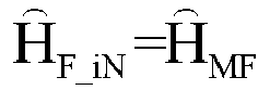

- Step S604. Filter the determined channel estimate


- Step S605. Estimate sending content of all symbols iN+2 to (i+1)N+1 by the channel estimate

- It should be noted that, a pilot symbol is usually a known symbol during channel estimation. Therefore, when received data symbols are demodulated or estimated, the pilot symbol may not be demodulated or estimated. Instead, the known pilot symbol may directly be used. Apparently, the pilot symbol may also be demodulated or estimated to ensure accuracy of the pilot symbol, thereby ensuring channel estimation accuracy and improving channel estimation performance.
- Further, an example in which the first channel estimation manner is the FFT channel estimation manner and the second channel estimation manner is the matched filtering channel estimation manner is used theoretically blow to show the effects of the foregoing embodiments.
- Specifically, if a transmitted chirp signal is


R represents a receiving signal vector, and R=(r 0, r 1, ...,r N-1) T , where N=2 SF , and ri represents an ith chirp receiving signal sampling value in a symbol; W represents white Gaussian noise, and W = (w 0, w 1,...,w N-1) T ; H represents a channel estimate, and H=(h-L1 ,...,h -1 ,h 0, h 1 ,h 2 ,...,h L2-1) T because of impact of a filter, where hl represents a channel response value of a 1st path, h L2-1 represents an h value corresponding to a maximum delay of a channel under impact of a filter, and h -L1 represents an h value corresponding to a maximum delay after a channel extends forward under impact of a filter; and X represents a matrix formed by sending signals, and may be represented as:


- When the matched filtering channel estimation manner is used to perform channel estimation on a pilot symbol, the estimation manner shown in
FIG. 3 may be used. That is, convolution operation is performed on a received pilot symbol and a matched filter, to obtain a matched filtering channel estimate of the pilot symbol, which may be marked as


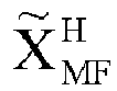

- For the matched filtering channel estimation (in which sending content of preceding and next symbols may be different):

XMF_ ideal, XMF_1, XMF_2, XMF_3, and XMF_4 are as follows:

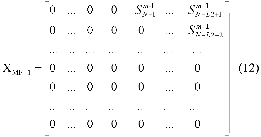
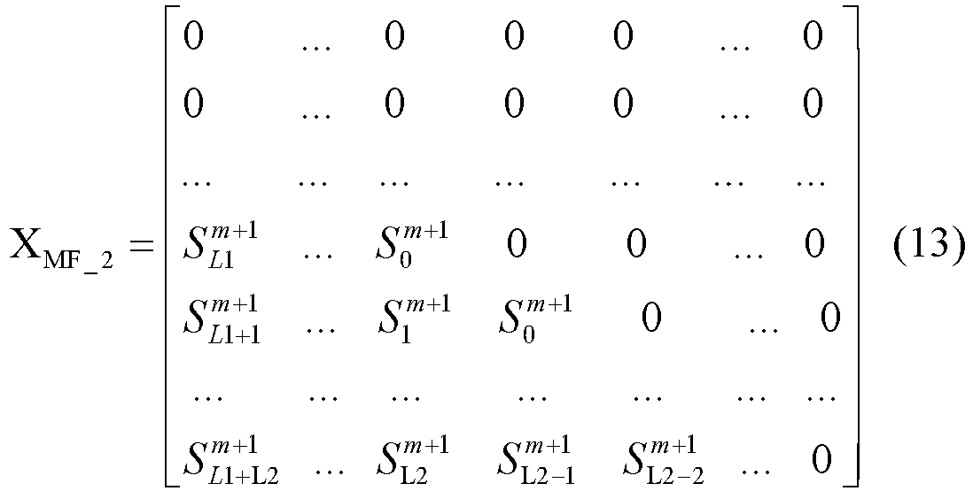


- The channel estimation is:


- When the FFT channel estimation manner is used to perform channel estimation on a pilot symbol, the estimation manner shown in
FIG. 4 may be used. That is, a received pilot symbol is multiplied by a conjugate of a sent pilot symbol first, and then IFFT is performed, and then a transformation result is multiplied by a rotation phase, to obtain an FFT channel estimate of the pilot symbol, which may be marked as ĤFFT . The rotation phase may be obtained according to an initial phase of the pilot symbol and a multipath index, and may be specifically obtained by the formula


- B can be derived to be:

- Channel estimation of ĤFFT =(ĥ 0,ĥ 1, ĥ 2,...,ĥ L2-1) T is estimated to be:


line 1 to line L2 of B, and X=XFFT_ideal + IFFT_1 + IFFT_2 -IFFT_3- IFFT_4 , where XFFT_ideal , IFFT_1, IFFT_2 , IFFT_3, and IFFT_4 are as follows:


- The channel estimation is:


- The following may be obtained by analyzing the interference ISI:
- 1. When the preceding data symbol of the pilot symbol and the next data symbol of the pilot symbol are the same as the pilot symbol, that is, IFFT_i = I MF_i = 0, i =1∼ 4, if no interference ISI exists, results of the matched filtering channel estimation and the FFT channel estimation are the same;
- 2. When the preceding data symbol of the pilot symbol and the next data symbol of the pilot symbol are different from the pilot symbol, that is, IFFT_i ≠ 0, I MF_i ≠ 0, i =1 ∼4, for ĥ 0, the two channel estimation manners have the same interference ISI. In the FFT channel estimation manner, the ISI impact rarely changes for ĥi,i>0 as i becomes greater. In the matched filtering channel estimation, the ISI impact becomes greater for ĥi,i<0 and smaller for ĥi,i>0 as i becomes greater. In an actual channel, ĥi signal energy mainly exists when i>0. Therefore, for ĥi,i >0 , performance of the matched filtering channel estimation manner is better;
- 3. When the preceding data symbol of the pilot symbol is the same as the pilot symbol and the next data symbol of the pilot symbol is different from the pilot symbol, that is, I MF_1 = I MF_3 = I FFT_1 = I FFT_3 = 0, and IFFT_i ≠ 0, I MF_i ≠ 0, i = 2,4, in the FFT channel estimation manner, the ISI impact rarely changes for ĥi,i >0 as i becomes greater. In the matched filtering channel estimation, the ISI impact becomes greater for ĥi,i<0 as i becomes greater. Therefore, performance of the FFT channel estimation manner is better;
- 4. When the preceding data symbol of the pilot symbol is different from the pilot symbol and the next data symbol of the pilot symbol is the same as the pilot symbol, that is, I MF_2 = I MF_4 = I FFT_2 = I FFT_4 = 0, and IFFT_i ≠ 0, I MF_i ≠ 0, i = 1,3 , in the FFT channel estimation manner, the ISI impact rarely changes for ĥi,i>0 as i becomes greater. In the matched filtering channel estimation, the ISI impact becomes smaller for ĥi,i<0 as i becomes greater. Therefore, performance of the matched filtering channel estimation is better.
- For the effects of channel estimation performed when the first channel estimation manner is the LS channel estimation manner and the second channel estimation manner is the matched filtering channel estimation manner, and when the first channel estimation manner is the MMSE channel estimation manner and the second channel estimation manner is the matched filtering channel estimation manner, corresponding theoretical analysis is not provided herein.
- It can be learned from the above that, channel estimation is performed in any of the manners in Table 3 according to the content of the pilot symbol and the content of the preceding and next data symbols of the pilot symbol, so that the obtained channel estimate of each pilot symbol is good. This can ensure accuracy of the channel estimate and improve channel estimation performance and demodulation performance of a linear frequency modulation signal.
- In this embodiment, a suitable channel estimate is selected from a plurality of channel estimates according to content of the next pilot symbol and the content of the preceding and next data symbols, so that accuracy of the channel estimate is improved. In this way, channel estimation performance and demodulation performance of a linear frequency modulation signal can be improved.
- For a fourth embodiment of the channel estimation method:
Refer toFIG. 9 , the channel estimation method for a linear frequency modulation communications system may include the following steps: - Step S701. Perform channel estimation on each pilot symbol in a first channel estimation manner and a second channel estimation manner, to obtain a first channel estimate and a second channel estimate. The first channel estimation manner is an FFT channel estimation manner, and the second channel estimation manner is a matched filtering channel estimation manner. Please refer to relevant description in step S501, and details are not described herein again.
- Step S702. Demodulate preceding and next data symbols of a next pilot symbol in advance according to a channel estimate of a current pilot symbol, to obtain content of the preceding and next data symbols of the next pilot symbol, and estimate a delay spread or a maximum path of a channel.
- It should be noted that, for the demodulating preceding and next data symbols of a next pilot symbol in advance according to a channel estimate of a current pilot symbol, to obtain content of the preceding and next data symbols of the next pilot symbol in step S702, please refer to relevant description in step S502, and details are not described herein again.
- Further, optionally, before selecting the channel estimate of the next pilot symbol as the channel estimate of the current pilot symbol to demodulate in advance the preceding and next data symbols of the next pilot symbol, the method further includes filtering the selected channel estimate of the next pilot symbol. Please refer to relevant description in step S502, and details are not described herein again.
- How to estimate a delay spread or a maximum path of the channel is mainly described herein. It should be noted that, estimation of a delay spread or a maximum path may be performed at an interval of a preset number (for example, 1, 2 and the like) of pilot symbols.
- Optionally, in some embodiments, the estimating a delay spread or a maximum path of the channel includes: obtaining a first delay spread or a first maximum path according to a synchronous signal; obtaining a second delay spread or a second maximum path according to the pilot symbol; and estimating the delay spread of the channel according to at least one of the first delay spread and the second delay spread, or estimating the maximum path of the channel according to at least one of the first maximum path and the second maximum path.
- Further, optionally, the obtaining a first delay spread or a first maximum path according to a synchronous signal includes: performing, if the synchronous signal is sent in an up chirp manner, pointwise multiplication on a received synchronous signal and a conjugate of the sent synchronous signal, and performing IFFT, to obtain a first power spectrum; or performing, if the synchronous signal is sent in a down chirp manner, pointwise multiplication on a received synchronous signal and a conjugate of the sent synchronous signal, and performing FFT, to obtain a second power spectrum; and obtaining the first delay spread according to the first power spectrum or the second power spectrum through calculation, or obtaining the first maximum path according to the first power spectrum or the second power spectrum through calculation.
- Further, optionally, the obtaining a second delay spread or a second maximum path according to the pilot symbol includes: performing, if the pilot symbol is sent in an up chirp manner, pointwise multiplication on a received pilot symbol and a conjugate of the sent pilot symbol, and performing IFFT, to obtain a third power spectrum; or performing, if the pilot symbol is sent in a down chirp manner, pointwise multiplication on a received pilot symbol and a conjugate of the sent pilot symbol, and performing FFT, to obtain a fourth power spectrum; and obtaining the second delay spread according to the third power spectrum or the fourth power spectrum through calculation, or obtaining the second maximum path according to the third power spectrum or the fourth power spectrum through calculation.
- Further, optionally, the estimating the delay spread of the channel according to at least one of the first delay spread and the second delay spread includes: filtering the first delay spread to obtain the delay spread of the channel, or filtering the second delay spread to obtain the delay spread of the channel, or performing weighting calculation on the filtered first delay spread and the filtered second delay spread, to obtain the delay spread of the channel.
- Further, optionally, the estimating the maximum path of the channel according to at least one of the first maximum path and the second maximum path includes: filtering the first maximum path to obtain the maximum path of the channel, or filtering the second maximum path to obtain the maximum path of the channel, or performing weighting calculation on the filtered first maximum path and the filtered second maximum path, to obtain the maximum path of the channel.
- It should be noted that, for the estimating a delay spread or a maximum path of the channel, please refer to relevant description in step S201, and details are not described herein again.
- Step S703. Select a channel estimate of the next pilot symbol from the first channel estimate and the second channel estimate according to the content of the preceding and next data symbols of the next pilot symbol and the delay spread or the maximum path, to obtain a channel estimate of each pilot symbol.
- That is, in this application, the channel estimate of the next pilot symbol may be obtained according to the content of the next pilot symbol, the content of the preceding and next data symbols of the next pilot symbol, and the delay spread. Or, the channel estimate of the next pilot symbol may be obtained according to the content of the next pilot symbol, the content of the preceding and next data symbols of the next pilot symbol, and the maximum path. During actual application, either of the delay spread and the maximum path may be used.
- Specifically, supposing that the current pilot symbol is the first pilot symbol, for example, the
pilot symbol 0 shown inFIG. 1 , after the content of the pilot symbol N, the data symbol N-1 and the data symbol N+1 is estimated according to the channel estimate of thepilot symbol 0, the channel estimate of the pilot symbol N may be determined from the first channel estimate (that is, the FFT channel estimate) and the second channel estimate (that is, the matched filtering channel estimate) according to the content of the pilot symbol N, the data symbol N-1 and the data symbol N+1, and the delay spread (or the maximum path) of the channel estimation obtained through estimation. When the pilot symbol is not the first pilot symbol, for example, is the pilot symbol N shown inFIG. 1 , after the content of the pilot symbol 2N, the data symbol 2N-1 and the data symbol 2N+1 is estimated according to the channel estimate of the pilot symbol N, the channel estimate of the pilot symbol 2N may be determined from the first channel estimate (that is, the FFT channel estimate) and the second channel estimate (that is, the matched filtering channel estimate) according to the content of the pilot symbol 2N, the data symbol 2N-1 and the data symbol 2N+1, and the delay spread (or the maximum path) of the channel estimation obtained through estimation. The rest can be deduced by analog, until a channel estimate of each pilot symbol is obtained. - Optionally, in some embodiments, the selecting a channel estimate of the next pilot symbol from the first channel estimate and the second channel estimate according to the content of the preceding and next data symbols of the next pilot symbol and the delay spread or the maximum path includes: when the delay spread or the maximum path is equal to or greater than a preset threshold, if the content of the preceding data symbol of the next pilot symbol is the same as content of the next pilot symbol, selecting the first channel estimate as the channel estimate of the next pilot symbol; otherwise, selecting the second channel estimate as the channel estimate of the next pilot symbol; or when the delay spread or the maximum path is less than the preset threshold, if the content of the next data symbol of the next pilot symbol is the same as the content of the next pilot symbol, selecting the second channel estimate as the channel estimate of the next pilot symbol; otherwise, selecting the first channel estimate as the channel estimate of the next pilot symbol.
- Specifically, supposing that the current pilot symbol is the first pilot symbol, for example, the
pilot symbol 0 shown inFIG. 1 , when the delay spread (or the maximum path) obtained at the pilot symbol N is less than the preset threshold, for example, 0.25 µs, if the content of the next data symbol N+1 of the pilot symbol N is the same as the content of the pilot symbol N, the channel estimate of the pilot symbol N is an estimate obtained by performing channel estimation in the second channel estimation manner, that is, the second channel estimate (that is, the matched filtering channel estimate); otherwise, the channel estimate of the pilot symbol N is an estimate obtained by performing channel estimation in the first channel estimation manner, that is, the first channel estimate (that is, the FFT channel estimate). When the delay spread (or the maximum path) obtained at the pilot symbol N is equal to or greater than the preset threshold, for example, 0.25 µs, if the content of the preceding data symbol N-1 of the pilot symbol N is the same as the content of the pilot symbol N, the channel estimate of the pilot symbol N is an estimate obtained by performing channel estimation in the first channel estimation manner, that is, the first channel estimate (that is, the FFT channel estimate); otherwise, the channel estimate of the pilot symbol N is an estimate obtained by performing channel estimation in the second channel estimation manner, that is, the second channel estimate (that is, the matched filtering channel estimate). - Similarly, if the pilot symbol is not the first pilot symbol, for example, is the pilot symbol N shown in
FIG. 1 , when the delay spread (or the maximum path) obtained at the pilot symbol 2N is less than the preset threshold, for example, 0.25 µs, if the content of the next data symbol 2N+1 of the pilot symbol 2N is the same as the content of the pilot symbol 2N, the channel estimate of the pilot symbol 2N is an estimate obtained by performing channel estimation in the second channel estimation manner, that is, the second channel estimate (that is, the matched filtering channel estimate); otherwise, the channel estimate of the pilot symbol 2N is an estimate obtained by performing channel estimation in the first channel estimation manner, that is, the first channel estimate (that is, the FFT channel estimate). When the delay spread (or the maximum path) obtained at the pilot symbol 2N is equal to or greater than the preset threshold, for example, 0.25 µs, if the content of the preceding data symbol 2N-1 of the pilot symbol 2N is the same as the content of the pilot symbol 2N, the channel estimate of the pilot symbol 2N is an estimate obtained by performing channel estimation in the first channel estimation manner, that is, the first channel estimate (that is, the FFT channel estimate); otherwise, the channel estimate of the pilot symbol 2N is an estimate obtained by performing channel estimation in the second channel estimation manner, that is, the second channel estimate (that is, the matched filtering channel estimate). - The channel estimate of each pilot symbol can be obtained by analog. In short, channel estimation may be performed in any of the manners in Table 4 according to the content of the pilot symbol, the content of the preceding and next data symbols of the pilot symbol, and the delay spread or the maximum path, to obtain the channel estimate of each pilot symbol.
Table 4 Seque nce A relationship between content of a pilot symbol and content of a preceding data symbol of the pilot symbol A relationship between content of a pilot symbol and content of a next data symbol of the pilot symbol A channel estimation manner of a pilot symbol when a delay spread or a maximum path is equal to or greater than a preset threshold A channel estimation manner of a pilot symbol when a delay spread or a maximum path is less than a preset threshold 1 Same Same FFT channel estimation manner or matched filtering channel estimation manner Matched filtering channel estimation manner or FFT channel estimation manner 2 Same Different FFT channel estimation manner FFT channel estimation manner 3 Different Same Matched filtering channel estimation manner Matched filtering channel estimation manner 4 Different Different Matched filtering channel estimation manner FFT channel estimation manner - It should be noted that, in Table 4, the first channel estimation manner is the FFT channel estimation manner, and the second channel estimation manner is the matched filtering channel estimation manner.
- In addition, it should be noted that, when the current pilot symbol is the first pilot symbol, for example, the
pilot symbol 0 shown inFIG. 1 , the second channel estimate (that is, the matched filtering channel estimate) may be regarded as the channel estimate of the first pilot symbol by default. In addition, when both the content of the preceding and next data symbols of the pilot symbol is the same as the content of the pilot symbol, as the first case shown in Table 4, whatever the delay spread or the maximum path is, the channel estimate of the pilot symbol may be obtained in the FFT channel estimation manner or the matched filtering channel estimation manner, and there is little difference between accuracy of obtained channel estimates. - In a specific example, refer to
FIG. 10 , the channel estimation method for a linear frequency modulation communications system may include: - Step S801. Perform channel estimation on each pilot symbol in the matched filtering channel estimation manner and the FFT channel estimation manner, to obtain a matched filtering channel estimate and an FFT channel estimate of each pilot symbol, which may be respectively marked as


- Step S802. When the pilot symbol is the
first pilot symbol 0, regard the matched filtering channel estimate as the channel estimate of thepilot symbol 0 by default, which may be marked as
symbols 1 to N+1 according to the channel estimate
pilot symbol 0. - Step S803. Select a channel estimate of a pilot symbol iN according to content of preceding and next data symbols iN-1 and iN+1 of the pilot symbol iN and a delay spread or a maximum path, which may be marked as

- A specific manner is as follows. Estimation is performed at an interval of one or a plurality of pilot symbols to obtain a delay spread or a maximum path of the channel. When the delay spread or the maximum path is equal to or greater than the preset threshold (for example, 0.25 µs), it is considered that the delay spread or the maximum path is great; otherwise, it is considered that the delay spread or the maximum path is small. If the delay spread or the maximum path is great, when the content of the data symbol iN-1 is the same as the content of the pilot symbol iN, the FFT channel estimate


- Step S804. Filter the determined channel estimate


- Step S805. Estimate sending content of all symbols iN+2 to (i+1)N+1 by the channel estimate

- Further, whether channel estimation performance is improved may be verified by an emulation test. For example, a system bandwidth may be set to 3.6 MHz, a spreading factor to 3, and a delay spread threshold to 0.25 µs. It can be determined according to the threshold that channel models ETU and EVA are of large delay spreads, and channel models AWGN and EPA are of small delay spreads. Then, emulation analysis is performed according to these channels. As shown in
FIG. 11a andFIG. 11b , it can be determined from an emulation result that the channel estimation performance after optimization is apparently improved. - In this embodiment, a suitable channel estimate is selected from a plurality of channel estimates according to content of the next pilot symbol, the content of the preceding and next data symbols, and the delay spread or the maximum path of the channel. This can further improve accuracy of the channel estimate and effectively improve channel estimation performance and demodulation performance of a linear frequency modulation signal.
- For a fifth embodiment of the channel estimation method:
Refer toFIG. 12 , the channel estimation method for a linear frequency modulation communications system may include the following steps: - Step S901. Perform channel estimation on each pilot symbol in a first channel estimation manner and a second channel estimation manner, to obtain a first channel estimate and a second channel estimate. The first channel estimation manner includes either of an LS channel estimation manner and an MMSE channel estimation manner, and the second channel estimation manner includes a matched filtering channel estimation manner. Please refer to relevant description in step S501, and details are not described herein again.
- Step S902. Demodulate preceding and next data symbols of a next pilot symbol in advance according to a channel estimate of a current pilot symbol, to obtain content of the preceding and next data symbols of the next pilot symbol, and estimate a delay spread or a maximum path of a channel.
- It should be noted that, for the demodulating preceding and next data symbols of a next pilot symbol in advance according to a channel estimate of a current pilot symbol, to obtain content of the preceding and next data symbols of the next pilot symbol in step S902, please refer to relevant description in step S502, and details are not described herein again.
- Further, optionally, before selecting the channel estimate of the next pilot symbol as the channel estimate of the current pilot symbol to demodulate in advance the preceding and next data symbols of the next pilot symbol, the method further includes filtering the selected channel estimate of the next pilot symbol. Please refer to relevant description in step S502, and details are not described herein again.
- How to estimate a delay spread or a maximum path of the channel is mainly described herein. It should be noted that, estimation of a delay spread or a maximum path may be performed at an interval of a preset number (for example, 1, 2 and the like) of pilot symbols.
- Optionally, in some embodiments, the estimating a delay spread or a maximum path of the channel includes: obtaining a first delay spread or a first maximum path according to a synchronous signal; obtaining a second delay spread or a second maximum path according to the pilot symbol; and estimating the delay spread of the channel according to at least one of the first delay spread and the second delay spread, or estimating the maximum path of the channel according to at least one of the first maximum path and the second maximum path.
- Further, optionally, the obtaining a first delay spread or a first maximum path according to a synchronous signal includes: performing, if the synchronous signal is sent in an up chirp manner, pointwise multiplication on a received synchronous signal and a conjugate of the sent synchronous signal, and performing IFFT, to obtain a first power spectrum; or performing, if the synchronous signal is sent in a down chirp manner, pointwise multiplication on a received synchronous signal and a conjugate of the sent synchronous signal, and performing FFT, to obtain a second power spectrum; and obtaining the first delay spread according to the first power spectrum or the second power spectrum through calculation, or obtaining the first maximum path according to the first power spectrum or the second power spectrum through calculation.
- Further, optionally, the obtaining a second delay spread or a second maximum path according to the pilot symbol includes: performing, if the pilot symbol is sent in an up chirp manner, pointwise multiplication on a received pilot symbol and a conjugate of the sent pilot symbol, and performing IFFT, to obtain a third power spectrum; or performing, if the pilot symbol is sent in a down chirp manner, pointwise multiplication on a received pilot symbol and a conjugate of the sent pilot symbol, and performing FFT, to obtain a fourth power spectrum; and obtaining the second delay spread according to the third power spectrum or the fourth power spectrum through calculation, or obtaining the second maximum path according to the third power spectrum or the fourth power spectrum through calculation.
- Further, optionally, the estimating the delay spread of the channel according to at least one of the first delay spread and the second delay spread includes: filtering the first delay spread to obtain the delay spread of the channel, or filtering the second delay spread to obtain the delay spread of the channel, or performing weighting calculation on the filtered first delay spread and the filtered second delay spread, to obtain the delay spread of the channel.
- Further, optionally, the estimating the maximum path of the channel according to at least one of the first maximum path and the second maximum path includes: filtering the first maximum path to obtain the maximum path of the channel, or filtering the second maximum path to obtain the maximum path of the channel, or performing weighting calculation on the filtered first maximum path and the filtered second maximum path, to obtain the maximum path of the channel.
- It should be noted that, for the estimating a delay spread or a maximum path of the channel, please refer to relevant description in step S201, and details are not described herein again.
- Step S903. Select a channel estimate of the next pilot symbol from the first channel estimate and the second channel estimate according to the content of the preceding and next data symbols of the next pilot symbol and the delay spread or the maximum path, to obtain a channel estimate of each pilot symbol.
- That is, in this application, the channel estimate of the next pilot symbol may be obtained according to the content of the next pilot symbol, the content of the preceding and next data symbols of the next pilot symbol, and the delay spread. Or, the channel estimate of the next pilot symbol may be obtained according to the content of the next pilot symbol, the content of the preceding and next data symbols of the next pilot symbol, and the maximum path. During actual application, either of the delay spread and the maximum path may be used.
- Specifically, supposing that the current pilot symbol is the first pilot symbol, for example, the
pilot symbol 0 shown inFIG. 1 , after the content of the pilot symbol N, the data symbol N-1 and the data symbol N+1 is estimated according to the channel estimate of thepilot symbol 0, the channel estimate of the pilot symbol N may be determined from the first channel estimate (for example, the LS channel estimate or the MMSE channel estimate) and the second channel estimate (for example, the matched filtering channel estimate) according to the content of the pilot symbol N, the data symbol N-1 and the data symbol N+1, and the delay spread (or the maximum path) of the channel estimation obtained through estimation. When the pilot symbol is not the first pilot symbol, for example, is the pilot symbol N shown inFIG. 1 , after the content of the pilot symbol 2N, the data symbol 2N-1 and the data symbol 2N+1 is estimated according to the channel estimate of the pilot symbol N, the channel estimate of the pilot symbol 2N may be determined from the first channel estimate (for example, the LS channel estimate or the MMSE channel estimate) and the second channel estimate (for example, the matched filtering channel estimate) according to the content of the pilot symbol 2N, the data symbol 2N-1 and the data symbol 2N+1, and the delay spread (or the maximum path) of the channel estimation obtained through estimation. The rest can be deduced by analog, until a channel estimate of each pilot symbol is obtained. - Optionally, in some embodiments, the selecting a channel estimate of the next pilot symbol from the first channel estimate and the second channel estimate according to the content of the preceding and next data symbols of the next pilot symbol and the delay spread or the maximum path includes: when the delay spread or the maximum path is equal to or greater than a preset threshold, if the content of the preceding data symbol of the next pilot symbol is the same as content of the next pilot symbol, selecting the first channel estimate as the channel estimate of the next pilot symbol; otherwise, selecting the second channel estimate as the channel estimate of the next pilot symbol; or when the delay spread or the maximum path is less than the preset threshold, if the content of the next data symbol of the next pilot symbol is the same as the content of the next pilot symbol, selecting the second channel estimate as the channel estimate of the next pilot symbol; otherwise, selecting the first channel estimate as the channel estimate of the next pilot symbol.
- Specifically, supposing that the current pilot symbol is the first pilot symbol, for example, the
pilot symbol 0 shown inFIG. 1 , when the delay spread (or maximum path) obtained at the pilot symbol N is less than the preset threshold, for example, 0.25 µs, if the content of the next data symbol N+1 of the pilot symbol N is the same as the content of the pilot symbol N, the channel estimate of the pilot symbol N is an estimate obtained by performing channel estimation in the second channel estimation manner, that is, the second channel estimate (for example, the matched filtering channel estimate); otherwise, the channel estimate of the pilot symbol N is an estimate obtained by performing channel estimation in the first channel estimation manner, that is, the first channel estimate (for example, the LS channel estimate or the MMSE channel estimate). When the delay spread (or the maximum path) obtained at the pilot symbol N is equal to or greater than the preset threshold, for example, 0.25 µs, if the content of the preceding data symbol N-1 of the pilot symbol N is the same as the content of the pilot symbol N, the channel estimate of the pilot symbol N is an estimate obtained by performing channel estimation in the first channel estimation manner, that is, the first channel estimate (for example, the LS channel estimate or the MMSE channel estimate); otherwise, the channel estimate of the pilot symbol N is an estimate obtained by performing channel estimation in the second channel estimation manner, that is, the second channel estimate (for example, the matched filtering channel estimate). - Similarly, if the pilot symbol is not the first pilot symbol, for example, is the pilot symbol N shown in
FIG. 1 , when the delay spread (or the maximum path) obtained at the pilot symbol 2N is less than the preset threshold, for example, 0.25 µs, if the content of the next data symbol 2N+1 of the pilot symbol 2N is the same as the content of the pilot symbol 2N, the channel estimate of the pilot symbol 2N is an estimate obtained by performing channel estimation in the second channel estimation manner, that is, the second channel estimate (for example, the matched filtering channel estimate); otherwise, the channel estimate of the pilot symbol 2N is an estimate obtained by performing channel estimation in the first channel estimation manner, that is, the first channel estimate (for example, the LS channel estimate or the MMSE channel estimate). When the delay spread (or the maximum path) obtained at the pilot symbol 2N is equal to or greater than the preset threshold, for example, 0.25 µs, if the content of the preceding data symbol 2N-1 of the pilot symbol 2N is the same as the content of the pilot symbol 2N, the channel estimate of the pilot symbol 2N is an estimate obtained by performing channel estimation in the first channel estimation manner, that is, the first channel estimate (for example, the LS channel estimate or the MMSE channel estimate); otherwise, the channel estimate of the pilot symbol 2N is an estimate obtained by performing channel estimation in the second channel estimation manner, that is, the second channel estimate (for example, the matched filtering channel estimate). - The channel estimate of each pilot symbol can be obtained by analog. In short, channel estimation may be performed in any of the manners in Table 5 according to the content of the pilot symbol, the content of the preceding and next data symbols of the pilot symbol, and the delay spread or the maximum path, to obtain the channel estimate of each pilot symbol.
Table 5 Seque nce A relationship between content of a pilot symbol and content of a preceding data symbol of the pilot symbol A relationship between content of a pilot symbol and content of a next data symbol of the pilot symbol A channel estimation manner of a pilot symbol when a delay spread or a maximum path is equal to or greater than a preset threshold A channel estimation manner of a pilot symbol when a delay spread or a maximum path is less than a preset threshold 1 Same Same First channel estimation manner or second channel estimation manner Second channel estimation manner or first channel estimation manner 2 Same Different First channel estimation manner First channel estimation manner 3 Different Same Second channel estimation manner Second channel estimation manner 4 Different Different Second channel estimation manner First channel estimation manner - It should be noted that, in Table 5, the first channel estimation manner is the LS channel estimation manner or the MMSE channel estimation manner, and the second channel estimation manner is the matched filtering channel estimation manner.
- In addition, it should be noted that, when the current pilot symbol is the first pilot symbol, for example, the
pilot symbol 0 shown inFIG. 1 , the second channel estimate (for example, the matched filtering channel estimate) may be regarded as the channel estimate of the first pilot symbol by default. In addition, when both the content of the preceding and next data symbols of the pilot symbol is the same as the content of the pilot symbol, as the first case shown in Table 5, whatever the delay spread or the maximum path is, the channel estimate of the pilot symbol may be obtained in the first channel estimation manner or the second channel estimation manner, and there is little difference between accuracy of obtained channel estimates. - In this embodiment, a suitable channel estimate is selected from a plurality of channel estimates according to content of the next pilot symbol, the content of the preceding and next data symbols, and the delay spread or the maximum path of the channel. This can further improve accuracy of the channel estimate and effectively improve channel estimation performance and demodulation performance of a linear frequency modulation signal.
- Based on the above, the channel estimation method for a linear frequency modulation communications system according to the embodiments of the present disclosure can effectively ensure accuracy of the channel estimate and improve the channel estimation performance and demodulation performance of a linear frequency modulation signal, and is especially suitable for a small multipath channel and a small spreading factor SF.
- The channel estimation apparatus for a linear frequency modulation communications system of this application is described in detail below with reference to the accompanying drawings.
- For a first embodiment of the channel estimation apparatus:
Refer toFIG. 13 , the channel estimation apparatus for a linear frequency modulation communications system may include: afirst demodulation module 110 and a firstchannel estimation module 120. Thefirst demodulation module 110 is configured to demodulate preceding and next data symbols of a next pilot symbol in advance according to a channel estimate of a current pilot symbol, to obtain content of the preceding and next data symbols of the next pilot symbol; and the firstchannel estimation module 120 is configured to adjust a start location of the next pilot symbol according to content of the next pilot symbol and the content of the preceding and next data symbols of the next pilot symbol, and perform channel estimation on the next pilot symbol at the start location, to obtain a channel estimate of the next pilot symbol. - Optionally, in some embodiments, the first
channel estimation module 120 is specifically configured to: if the content of the next data symbol of the next pilot symbol is different from the content of the next pilot symbol, adjust the start location of the next pilot symbol to a first location, and perform channel estimation on the next pilot symbol at the first location, to obtain the channel estimate of the next pilot symbol; otherwise, adjust the start location of the next pilot symbol to a second location, and perform channel estimation on the next pilot symbol at the second location, to obtain the channel estimate of the next pilot symbol, where the first location is ahead of the second location. - Optionally, in some embodiments, the first
channel estimation module 120 is specifically configured to: perform channel estimation on the next pilot symbol at the start location in any of an FFT channel estimation manner, a matched filtering channel estimation manner, an LS channel estimation manner and an MMSE channel estimation manner, to obtain the channel estimate of the next pilot symbol. - Optionally, in some embodiments, refer to
FIG. 13 , the channel estimation apparatus for a linear frequency modulation communications system may further include: afirst filtering module 130, configured to: before thefirst demodulation module 110 demodulates preceding and next data symbols of a next pilot symbol in advance according to a channel estimate of a current pilot symbol, to obtain content of the preceding and next data symbols of the next pilot symbol, filter the channel estimate of the current pilot symbol. - It should be noted that, for the description of the first channel estimation apparatus for a linear frequency modulation communications system, please refer to the description of the first channel estimation method for a linear frequency modulation communications system in this application, and details are not described herein again.
- In another example, the channel estimation apparatus for a linear frequency modulation communications system includes a processor, and the processor is configured to execute the foregoing program modules stored in a memory. The program modules include: the
first demodulation module 110, configured to demodulate preceding and next data symbols of a next pilot symbol in advance according to a channel estimate of a current pilot symbol, to obtain content of the preceding and next data symbols of the next pilot symbol; the firstchannel estimation module 120, configured to adjust a start location of the next pilot symbol according to content of the next pilot symbol and the content of the preceding and next data symbols of the next pilot symbol, and perform channel estimation on the next pilot symbol at the start location, to obtain a channel estimate of the next pilot symbol; and thefirst filtering module 130, configured to: before thefirst demodulation module 110 demodulates preceding and next data symbols of a next pilot symbol in advance according to a channel estimate of a current pilot symbol, to obtain content of the preceding and next data symbols of the next pilot symbol, filter the channel estimate of the current pilot symbol. - For a second embodiment of the channel estimation apparatus:
Refer toFIG. 14 , the channel estimation apparatus for a linear frequency modulation communications system may include: afirst demodulation module 110, a firstchannel estimation module 120 and a first delay spreadestimation module 140. Thefirst demodulation module 110 is configured to demodulate preceding and next data symbols of a next pilot symbol in advance according to a channel estimate of a current pilot symbol, to obtain content of the preceding and next data symbols of the next pilot symbol; the first delay spreadestimation module 140 is configured to estimate a delay spread or a maximum path of a channel; and the firstchannel estimation module 120 is configured to adjust a start location of the next pilot symbol according to content of the next pilot symbol, the content of the preceding and next data symbols of the next pilot symbol, and the delay spread or the maximum path of the channel, and perform channel estimation on the next pilot symbol at the start location, to obtain a channel estimate of the next pilot symbol. - Optionally, in some embodiments, the first channel estimation module 120 is specifically configured to: when the delay spread or the maximum path is less than a preset threshold, if the content of the next data symbol of the next pilot symbol is the same as the content of the next pilot symbol, adjust the start location of the next pilot symbol to a second location, and perform channel estimation on the next pilot symbol at the second location, to obtain the channel estimate of the next pilot symbol; otherwise, adjust the start location of the next pilot symbol to a first location, and perform channel estimation on the next pilot symbol at the first location, to obtain the channel estimate of the next pilot symbol, where the first location is ahead of the second location; or when the delay spread or the maximum path is equal to or greater than the preset threshold, if the content of the preceding data symbol of the next pilot symbol is the same as the content of the next pilot symbol, adjust the start location of the next pilot symbol to the first location, and perform channel estimation on the next pilot symbol at the first location, to obtain the channel estimate of the next pilot symbol; otherwise, adjust the start location of the next pilot symbol to the second location, and perform channel estimation on the next pilot symbol at the second location, to obtain the channel estimate of the next pilot symbol.
- Optionally, in some embodiments, the first
channel estimation module 120 is specifically configured to: perform channel estimation on the next pilot symbol at the start location in any of an FFT channel estimation manner, a matched filtering channel estimation manner, an LS channel estimation manner and an MMSE channel estimation manner, to obtain the channel estimate of the next pilot symbol. - Optionally, in some embodiments, refer to
FIG. 14 , the channel estimation apparatus for a linear frequency modulation communications system may further include: afirst filtering module 130, configured to: before thefirst demodulation module 110 demodulates preceding and next data symbols of a next pilot symbol in advance according to a channel estimate of a current pilot symbol, to obtain content of the preceding and next data symbols of the next pilot symbol, filter the channel estimate of the current pilot symbol. - Optionally, in some embodiments, the first delay spread
estimation module 140 is specifically configured to: obtain a first delay spread or a first maximum path according to a synchronous signal; obtain a second delay spread or a second maximum path according to the pilot symbol; and estimate the delay spread of the channel according to at least one of the first delay spread and the second delay spread, or estimate the maximum path of the channel according to at least one of the first maximum path and the second maximum path. - Optionally, in some embodiments, the first delay spread
estimation module 140 is specifically configured to: perform, if the synchronous signal is sent in an up chirp manner, pointwise multiplication on a received synchronous signal and a conjugate of the sent synchronous signal, and perform IFFT, to obtain a first power spectrum; or perform, if the synchronous signal is sent in a down chirp manner, pointwise multiplication on a received synchronous signal and a conjugate of the sent synchronous signal, and perform FFT, to obtain a second power spectrum; and obtain the first delay spread according to the first power spectrum or the second power spectrum through calculation, or obtain the first maximum path according to the first power spectrum or the second power spectrum through calculation. - Optionally, in some embodiments, the first delay spread
estimation module 140 is specifically configured to: perform, if the pilot symbol is sent in an up chirp manner, pointwise multiplication on a received pilot symbol and a conjugate of the sent pilot symbol, and perform IFFT, to obtain a third power spectrum; or perform, if the pilot symbol is sent in a down chirp manner, pointwise multiplication on a received pilot symbol and a conjugate of the sent pilot symbol, and perform FFT, to obtain a fourth power spectrum; and obtain the second delay spread according to the third power spectrum or the fourth power spectrum through calculation, or obtain the second maximum path according to the third power spectrum or the fourth power spectrum through calculation. - Optionally, in some embodiments, the first delay spread
estimation module 140 is specifically configured to: when estimating the delay spread of the channel according to at least one of the first delay spread and the second delay spread, filter the first delay spread to obtain the delay spread of the channel, or filter the second delay spread to obtain the delay spread of the channel, or perform weighting calculation on the filtered first delay spread and the filtered second delay spread, to obtain the delay spread of the channel. - Optionally, in some embodiments, the first delay spread
estimation module 140 is specifically configured to: when estimating the maximum path of the channel according to at least one of the first maximum path and the second maximum path, filter the first maximum path to obtain the maximum path of the channel, or filter the second maximum path to obtain the maximum path of the channel, or perform weighting calculation on the filtered first maximum path and the filtered second maximum path, to obtain the maximum path of the channel. - It should be noted that, for description of the second channel estimation apparatus for a linear frequency modulation communications system, please refer to the description of the second channel estimation method for a linear frequency modulation communications system in this application, and details are not described herein again.
- In another example, the channel estimation apparatus for a linear frequency modulation communications system includes a processor, and the processor is configured to execute the foregoing program modules stored in a memory. The program modules include: the
first demodulation module 110, the firstchannel estimation module 120, the first delay spreadestimation module 140, and thefirst filtering module 130. - For a third embodiment of the channel estimation apparatus:
Refer toFIG. 15 , the channel estimation apparatus for a linear frequency modulation communications system includes: a secondchannel estimation module 210, asecond demodulation module 220 and afirst selection module 230. The secondchannel estimation module 210 is configured to perform channel estimation on each pilot symbol in a first channel estimation manner and a second channel estimation manner, to obtain a first channel estimate and a second channel estimate, where the first channel estimation manner includes either of an LS channel estimation manner and an MMSE channel estimation manner, and the second channel estimation manner includes a matched filtering channel estimation manner; thesecond demodulation module 220 is configured to demodulate preceding and next data symbols of a next pilot symbol in advance according to a channel estimate of a current pilot symbol, to obtain content of the preceding and next data symbols of the next pilot symbol; and thefirst selection module 230 is configured to select a channel estimate of the next pilot symbol from the first channel estimate and the second channel estimate according to the content of the preceding and next data symbols of the next pilot symbol, to obtain a channel estimate of each pilot symbol. - Optionally, in some embodiments, the
first selection module 230 is specifically configured to: select the first channel estimate as the channel estimate of the next pilot symbol if the content of the next data symbol of the next pilot symbol is different from content of the next pilot symbol; otherwise, select the second channel estimate as the channel estimate of the next pilot symbol. - Optionally, in some embodiments, the
first selection module 230 is further configured to: when the current pilot symbol is the first pilot symbol, regard the second channel estimate as the channel estimate of the first pilot symbol by default. - Optionally, in some embodiments, refer to
FIG. 15 , the channel estimation apparatus for a linear frequency modulation communications system may further include: asecond filtering module 240, configured to: before thesecond demodulation module 220 uses the selected channel estimate of the next pilot symbol as the channel estimate of the current pilot symbol to demodulate in advance the preceding and next data symbols of the next pilot symbol, filter the selected channel estimate of the next pilot symbol. - It should be noted that, for the description of the third channel estimation apparatus for a linear frequency modulation communications system, please refer to the description of the third channel estimation method for a linear frequency modulation communications system in this application, and details are not described herein again.
- In another example, the channel estimation apparatus for a linear frequency modulation communications system includes a processor, and the processor is configured to execute the foregoing program modules stored in a memory. The program modules include: the second
channel estimation module 210, thesecond demodulation module 220, thefirst selection module 230, and thesecond filtering module 240. - For a fourth embodiment of the channel estimation apparatus:
Refer toFIG. 16 , the channel estimation apparatus for a linear frequency modulation communications system includes: a thirdchannel estimation module 310, athird demodulation module 320, a third delay spreadestimation module 350, and asecond selection module 330. The thirdchannel estimation module 310 is configured to perform channel estimation on each pilot symbol in a first channel estimation manner and a second channel estimation manner, to obtain a first channel estimate and a second channel estimate, where the first channel estimation manner is an FFT channel estimation manner, and the second channel estimation manner is a matched filtering channel estimation manner; thethird demodulation module 320 is configured to demodulate preceding and next data symbols of a next pilot symbol in advance according to a channel estimate of a current pilot symbol, to obtain content of the preceding and next data symbols of the next pilot symbol; the third delay spreadestimation module 350 is configured to estimate a delay spread or a maximum path of the channel; and thesecond selection module 330 is configured to select a channel estimate of the next pilot symbol from the first channel estimate and the second channel estimate according to the content of the preceding and next data symbols of the next pilot symbol and the delay spread or the maximum path, to obtain a channel estimate of each pilot symbol. - Optionally, in some embodiments, the
second selection module 330 is specifically configured to: when the delay spread or the maximum path is equal to or greater than a preset threshold, if the content of the preceding data symbol of the next pilot symbol is the same as content of the next pilot symbol, select the first channel estimate as the channel estimate of the next pilot symbol; otherwise, select the second channel estimate as the channel estimate of the next pilot symbol; or when the delay spread or the maximum path is less than the preset threshold, if the content of the next data symbol of the next pilot symbol is the same as the content of the next pilot symbol, select the second channel estimate as the channel estimate of the next pilot symbol; otherwise, select the first channel estimate as the channel estimate of the next pilot symbol. - Optionally, in some embodiments, the
second selection module 330 is further configured to: when the current pilot symbol is the first pilot symbol, regard the second channel estimate as the channel estimate of the first pilot symbol by default. - Optionally, in some embodiments, refer to
FIG. 16 , the channel estimation apparatus for a linear frequency modulation communications system may further include: athird filtering module 340, configured to: before thethird demodulation module 320 uses the selected channel estimate of the next pilot symbol as the channel estimate of the current pilot symbol to demodulate in advance the preceding and next data symbols of the next pilot symbol, filter the selected channel estimate of the next pilot symbol. - Optionally, in some embodiments, the third delay spread
estimation module 350 is specifically configured to: obtain a first delay spread or a first maximum path according to a synchronous signal; obtain a second delay spread or a second maximum path according to the pilot symbol; and estimate the delay spread of the channel according to at least one of the first delay spread and the second delay spread, or estimate the maximum path of the channel according to at least one of the first maximum path and the second maximum path. - Optionally, in some embodiments, the third delay spread
estimation module 350 is specifically configured to: perform, if the synchronous signal is sent in an up chirp manner, pointwise multiplication on a received synchronous signal and a conjugate of the sent synchronous signal, and perform IFFT, to obtain a first power spectrum; or perform, if the synchronous signal is sent in a down chirp manner, pointwise multiplication on a received synchronous signal and a conjugate of the sent synchronous signal, and perform FFT, to obtain a second power spectrum; and obtain the first delay spread according to the first power spectrum or the second power spectrum through calculation, or obtain the first maximum path according to the first power spectrum or the second power spectrum through calculation. - Optionally, in some embodiments, the third delay spread
estimation module 350 is specifically configured to: perform, if the pilot symbol is sent in an up chirp manner, pointwise multiplication on a received pilot symbol and a conjugate of the sent pilot symbol, and perform IFFT, to obtain a third power spectrum; or perform, if the pilot symbol is sent in a down chirp manner, pointwise multiplication on a received pilot symbol and a conjugate of the sent pilot symbol, and perform FFT, to obtain a fourth power spectrum; and obtain the second delay spread according to the third power spectrum or the fourth power spectrum through calculation, or obtain the second maximum path according to the third power spectrum or the fourth power spectrum through calculation. - Optionally, in some embodiments, the third delay spread
estimation module 350 is specifically configured to: when estimating the delay spread of the channel according to at least one of the first delay spread and the second delay spread, filter the first delay spread to obtain the delay spread of the channel, or filter the second delay spread to obtain the delay spread of the channel, or perform weighting calculation on the filtered first delay spread and the filtered second delay spread, to obtain the delay spread of the channel. - Optionally, in some embodiments, the third delay spread
estimation module 350 is specifically configured to: when estimating the maximum path of the channel according to at least one of the first maximum path and the second maximum path, filter the first maximum path to obtain the maximum path of the channel, or filter the second maximum path to obtain the maximum path of the channel, or perform weighting calculation on the filtered first maximum path and the filtered second maximum path, to obtain the maximum path of the channel. - It should be noted that, for the description of the fourth channel estimation apparatus for a linear frequency modulation communications system, please refer to the description of the fourth channel estimation method for a linear frequency modulation communications system in this application, and details are not described herein again.
- In another example, the channel estimation apparatus for a linear frequency modulation communications system includes a processor, and the processor is configured to execute the foregoing program modules stored in a memory. The program modules include: the third
channel estimation module 310, thethird demodulation module 320, the third delay spreadestimation module 350, thesecond selection module 330 and thethird filtering module 340. - For a fifth embodiment of the channel estimation apparatus:
Refer toFIG. 17 , the channel estimation apparatus for a linear frequency modulation communications system includes: a secondchannel estimation module 210, asecond demodulation module 220, a second delay spreadestimation module 250 and afirst selection module 230. The secondchannel estimation module 210 is configured to perform channel estimation on each pilot symbol in a first channel estimation manner and a second channel estimation manner, to obtain a first channel estimate and a second channel estimate, where the first channel estimation manner includes either of an LS channel estimation manner and an MMSE channel estimation manner, and the second channel estimation manner includes a matched filtering channel estimation manner; thesecond demodulation module 220 is configured to demodulate preceding and next data symbols of a next pilot symbol in advance according to a channel estimate of a current pilot symbol, to obtain content of the preceding and next data symbols of the next pilot symbol; the second delay spreadestimation module 250 is configured to estimate a delay spread or a maximum path of the channel; and thefirst selection module 230 is configured to select a channel estimate of the next pilot symbol from the first channel estimate and the second channel estimate according to the content of the preceding and next data symbols of the next pilot symbol and the delay spread or the maximum path, to obtain a channel estimate of each pilot symbol. - Optionally, in some embodiments, the
first selection module 230 is specifically configured to: when the delay spread or the maximum path is equal to or greater than a preset threshold, if the content of the preceding data symbol of the next pilot symbol is the same as content of the next pilot symbol, select the first channel estimate as the channel estimate of the next pilot symbol; otherwise, select the second channel estimate as the channel estimate of the next pilot symbol; or when the delay spread or the maximum path is less than the preset threshold, if the content of the next data symbol of the next pilot symbol is the same as the content of the next pilot symbol, select the second channel estimate as the channel estimate of the next pilot symbol; otherwise, select the first channel estimate as the channel estimate of the next pilot symbol. - Optionally, in some embodiments, the
first selection module 230 is further configured to: when the current pilot symbol is the first pilot symbol, regard the second channel estimate as the channel estimate of the first pilot symbol by default. - Optionally, in some embodiments, refer to
FIG. 17 , the channel estimation apparatus for a linear frequency modulation communications system may further include: asecond filtering module 240, configured to: before thesecond demodulation module 220 uses the channel estimate of the next pilot symbol as the channel estimate of the current pilot symbol to demodulate in advance the preceding and next data symbols of the next pilot symbol, filter the selected channel estimate of the next pilot symbol. - Optionally, in some embodiments, the second delay spread
estimation module 250 is specifically configured to: obtain a first delay spread or a first maximum path according to a synchronous signal; obtain a second delay spread or a second maximum path according to the pilot symbol; and estimate the delay spread of the channel according to at least one of the first delay spread and the second delay spread, or estimate the maximum path of the channel according to at least one of the first maximum path and the second maximum path. - Optionally, in some embodiments, the second delay spread
estimation module 250 is specifically configured to: perform, if the synchronous signal is sent in an up chirp manner, pointwise multiplication on a received synchronous signal and a conjugate of the sent synchronous signal, and perform IFFT, to obtain a first power spectrum; or perform, if the synchronous signal is sent in a down chirp manner, pointwise multiplication on a received synchronous signal and a conjugate of the sent synchronous signal, and perform FFT, to obtain a second power spectrum; and obtain the first delay spread according to the first power spectrum or the second power spectrum through calculation, or obtain the first maximum path according to the first power spectrum or the second power spectrum through calculation. - Optionally, in some embodiments, the second delay spread
estimation module 250 is specifically configured to: perform, if the pilot symbol is sent in an up chirp manner, pointwise multiplication on a received pilot symbol and a conjugate of the sent pilot symbol, and perform IFFT, to obtain a third power spectrum; or perform, if the pilot symbol is sent in a down chirp manner, pointwise multiplication on a received pilot symbol and a conjugate of the sent pilot symbol, and perform FFT, to obtain a fourth power spectrum; and obtain the second delay spread according to the third power spectrum or the fourth power spectrum through calculation, or obtain the second maximum path according to the third power spectrum or the fourth power spectrum through calculation. - Optionally, in some embodiments, the second delay spread
estimation module 250 is specifically configured to: when estimating the delay spread of the channel according to at least one of the first delay spread and the second delay spread, filter the first delay spread to obtain the delay spread of the channel, or filter the second delay spread to obtain the delay spread of the channel, or perform weighting calculation on the filtered first delay spread and the filtered second delay spread, to obtain the delay spread of the channel. - Optionally, in some embodiments, the second delay spread
estimation module 250 is specifically configured to: when estimating the maximum path of the channel according to at least one of the first maximum path and the second maximum path, filter the first maximum path to obtain the maximum path of the channel, or filter the second maximum path to obtain the maximum path of the channel, or perform weighting calculation on the filtered first maximum path and the filtered second maximum path, to obtain the maximum path of the channel. - It should be noted that, for the description of the fifth channel estimation apparatus for a linear frequency modulation communications system, please refer to the description of the fifth channel estimation method for a linear frequency modulation communications system in this application, and details are not described herein again.
- In another example, the channel estimation apparatus for a linear frequency modulation communications system includes a processor, and the processor is configured to execute the foregoing program modules stored in a memory. The program modules include: the second
channel estimation module 210, thesecond demodulation module 220, the second delay spreadestimation module 250, thefirst selection module 230 and thesecond filtering module 240. - The channel estimation apparatus for a linear frequency modulation communications system according to the embodiments of the present disclosure can effectively ensure accuracy of the channel estimate and improve the channel estimation performance and demodulation performance of a linear frequency modulation signal, and is especially suitable for a small multipath channel and a small spreading factor SF.
- In some embodiments, a linear frequency modulation communications system is provided. The system may include any of the first to the fifth channel estimation apparatuses for a linear frequency modulation communications system. The system can effectively ensure accuracy of a channel estimate and improve channel estimation performance and demodulation performance of a linear frequency modulation signal by any of the channel estimation apparatuses for a linear frequency modulation communications system.
- In some embodiments, a computer-readable storage medium is provided. A channel estimation program for a linear frequency modulation communications system is stored in the computer-readable storage medium, and the channel estimation program is executed by a processor to achieve any of the first to the fifth channel estimation methods for a linear frequency modulation communications system. The storage medium can effectively ensure accuracy of a channel estimate and improve channel estimation performance and demodulation performance of a linear frequency modulation signal by performing any of the channel estimation methods for a linear frequency modulation communications system.
- In some embodiments, a chip is provided. The chip includes a memory and a processor. A computer program is stored in the memory, and the computer program is executed by the processor to achieve any of the first to the fifth channel estimation methods for a linear frequency modulation communications system. The chip can effectively ensure accuracy of a channel estimate and improve channel estimation performance and demodulation performance of a linear frequency modulation signal by performing any of the channel estimation methods for a linear frequency modulation communications system.
- It should be noted that, the logic and/or steps represented in the flow chart or described in other manners herein, for example, may be considered as a sequenced list of executable instructions for implementing logical functions, and may be implemented in any computer-readable medium, for use by instruction execution systems, apparatuses, or devices (such as computer-based systems, systems including processors, or other systems that can fetch instructions from the instruction execution systems, apparatuses, or devices and execute the instructions), or used in combination with these instruction execution systems, apparatuses, or devices. For the purposes of this specification, a "computer-readable medium" may be any apparatus that can contain, store, communicate, propagate, or transmit a program for use by instruction execution systems, apparatuses, or devices or in combination with these instruction execution systems, apparatuses, or devices. More specific examples (a non-exhaustive list) of the computer-readable medium include the following: an electrical connection (electronic device) with one or more wiring, a portable computer disk cartridge (magnetic device), a random access memory (RAM), a read-only memory (ROM), an erasable and editable read-only memory (an EPROM or a flash memory), a fiber optic device, and a portable compact disk read-only memory (CDROM). In addition, the computer-readable medium may even be a paper or other suitable mediums on which the program can be printed, because the program may be obtained electronically, for example, by optically scanning the paper or other mediums, followed by editing, interpreting, or processing in other suitable manners if necessary. The program is then stored in a computer memory.
- It should be understood that the present disclosure may be implemented by hardware, software, firmware, or a combination thereof. In the foregoing implementations, multiple steps or methods may be implemented by software or firmware that is stored in a memory and that is executed by a proper instruction execution system. For example, if implemented by hardware, as in another embodiment, this implementation may be implemented by any one or a combination of the following technologies known in the art: a discrete logic circuit with a logic gate circuit for implementing a logic function on a data symbol, an application-specific integrated circuit with a suitable combinational logic gate circuit, a programmable gate array (PGA), a field programmable gate array (FPGA), and the like.
- In the specification, the description of "one embodiment", "some embodiments", "an example", "a specific example" and "some examples" means that a specific feature, structure, material or characteristic described in combination with the embodiment (s) or example (s) are included in at least one embodiment or example of the present disclosure. In this specification, the schematic representation of the above terms does not necessarily refer to the same embodiment or example. Moreover, the specific features, structures, materials or characteristics described may be combined in any suitable manner in any one or more embodiments or examples.
- Moreover, the terms "first" and "second" are used only for the purpose of description and should not be construed as indicating or implying a relative importance, or implicitly indicating a quantity of indicated technical features. Therefore, features defined by "first" and "second" may explicitly or implicitly include at least one of the features. In description of the present disclosure, "a plurality of means at least two, for example, two or three, unless otherwise clearly and specifically limited.
- In the present disclosure, unless otherwise clearly limited, the terms "installation", "interconnection", "connection" and "fixation" etc. are intended to be understood in a broad sense. For example, the "connection" may be a fixed connection, removable connection or integral connection; may be a mechanical connection or electrical connection; may be a direct connection or indirect connection using a medium; and may be a communication or interaction between two elements, unless otherwise clearly specified and limited. Those of ordinary skill in the art may understand specific meanings of the above terms in the present disclosure based on a specific situation.
- Although the embodiments of the present disclosure have been illustrated and described above, it will be appreciated that the above embodiments are illustrative and should not be construed as limiting the scope of the present disclosure. Changes, modifications, substitutions and variations can be made to the above embodiments by a person of ordinary skill in the art within the scope of the present disclosure.
Claims (29)
- A channel estimation method for a linear frequency modulation communications system, comprising the following steps:demodulating preceding and next data symbols of a next pilot symbol in advance according to a channel estimate of a current pilot symbol, to obtain content of the preceding and next data symbols of the next pilot symbol; andadjusting a start location of the next pilot symbol according to content of the next pilot symbol and the content of the preceding and next data symbols of the next pilot symbol, and performing channel estimation on the next pilot symbol at the start location, to obtain a channel estimate of the next pilot symbol.
- The channel estimation method for a linear frequency modulation communications system according to claim 1, wherein the adjusting a start location of the next pilot symbol according to content of the next pilot symbol and the content of the preceding and next data symbols of the next pilot symbol, and performing channel estimation on the next pilot symbol at the start location, to obtain a channel estimate of the next pilot symbol comprises:
if the content of the next data symbol of the next pilot symbol is different from the content of the next pilot symbol, adjusting the start location of the next pilot symbol to a first location, and performing channel estimation on the next pilot symbol at the first location, to obtain the channel estimate of the next pilot symbol; otherwise, adjusting the start location of the next pilot symbol to a second location, and performing channel estimation on the next pilot symbol at the second location, to obtain the channel estimate of the next pilot symbol, wherein the first location is ahead of the second location. - The channel estimation method for a linear frequency modulation communications system according to claim 1, wherein the method further comprises:estimating a delay spread or a maximum path of a channel; andadjusting a start location of the next pilot symbol according to the content of the next pilot symbol, the content of the preceding and next data symbols of the next pilot symbol, and the delay spread or the maximum path, and performing channel estimation on the next pilot symbol at the start location, to obtain a channel estimate of the next pilot symbol.
- The channel estimation method for a linear frequency modulation communications system according to claim 3, wherein the adjusting a start location of the next pilot symbol according to the content of the next pilot symbol, the content of the preceding and next data symbols of the next pilot symbol, and the delay spread or the maximum path, and performing channel estimation on the next pilot symbol at the start location, to obtain a channel estimate of the next pilot symbol comprises:when the delay spread or the maximum path is less than a preset threshold, if the content of the next data symbol of the next pilot symbol is the same as the content of the next pilot symbol, adjusting the start location of the next pilot symbol to a second location, and performing channel estimation on the next pilot symbol at the second location, to obtain the channel estimate of the next pilot symbol; otherwise, adjusting the start location of the next pilot symbol to a first location, and performing channel estimation on the next pilot symbol at the first location, to obtain the channel estimate of the next pilot symbol, wherein the first location is ahead of the second location; orwhen the delay spread or the maximum path is equal to or greater than the preset threshold, if the content of the preceding data symbol of the next pilot symbol is the same as the content of the next pilot symbol, adjusting the start location of the next pilot symbol to the first location, and performing channel estimation on the next pilot symbol at the first location, to obtain the channel estimate of the next pilot symbol; otherwise, adjusting the start location of the next pilot symbol to the second location, and performing channel estimation on the next pilot symbol at the second location, to obtain the channel estimate of the next pilot symbol.
- The channel estimation method for a linear frequency modulation communications system according to claim 3, wherein the estimating a delay spread or a maximum path of a channel comprises:obtaining a first delay spread or a first maximum path according to a synchronous signal;obtaining a second delay spread or a second maximum path according to the pilot symbol; andestimating the delay spread of the channel according to at least one of the first delay spread and the second delay spread, or estimating the maximum path of the channel according to at least one of the first maximum path and the second maximum path.
- The channel estimation method for a linear frequency modulation communications system according to claim 5, wherein the obtaining a first delay spread or a first maximum path according to a synchronous signal comprises:performing, if the synchronous signal is sent in an up chirp manner, pointwise multiplication on a received synchronous signal and a conjugate of the sent synchronous signal, and performing inverse fast Fourier transform (IFFT), to obtain a first power spectrum; orperforming, if the synchronous signal is sent in a down chirp manner, pointwise multiplication on a received synchronous signal and a conjugate of the sent synchronous signal, and performing fast Fourier transform (FFT), to obtain a second power spectrum; andobtaining the first delay spread according to the first power spectrum or the second power spectrum through calculation, or obtaining the first maximum path according to the first power spectrum or the second power spectrum through calculation.
- The channel estimation method for a linear frequency modulation communications system according to claim 5, wherein the obtaining a second delay spread or a second maximum path according to the pilot symbol comprises:performing, if the pilot symbol is sent in an up chirp manner, pointwise multiplication on a received pilot symbol and a conjugate of the sent pilot symbol, and performing IFFT, to obtain a third power spectrum; orperforming, if the pilot symbol is sent in a down chirp manner, pointwise multiplication on a received pilot symbol and a conjugate of the sent pilot symbol, and performing FFT, to obtain a fourth power spectrum; andobtaining the second delay spread according to the third power spectrum or the fourth power spectrum through calculation, or obtaining the second maximum path according to the third power spectrum or the fourth power spectrum through calculation.
- The channel estimation method for a linear frequency modulation communications system according to claim 5, wherein the estimating the delay spread of the channel according to at least one of the first delay spread and the second delay spread comprises:
filtering the first delay spread to obtain the delay spread of the channel, or filtering the second delay spread to obtain the delay spread of the channel, or performing weighting calculation on the filtered first delay spread and the filtered second delay spread, to obtain the delay spread of the channel. - The channel estimation method for a linear frequency modulation communications system according to claim 5, wherein the estimating the maximum path of the channel according to at least one of the first maximum path and the second maximum path comprises:
filtering the first maximum path to obtain the maximum path of the channel, or filtering the second maximum path to obtain the maximum path of the channel, or performing weighting calculation on the filtered first maximum path and the filtered second maximum path, to obtain the maximum path of the channel. - The channel estimation method for a linear frequency modulation communications system according to any one of claims 1 to 9, wherein channel estimation is performed on the next pilot symbol at the start location in any of an FFT channel estimation manner, a matched filtering channel estimation manner, a least square (LS) channel estimation manner and a minimum mean square error (MMSE) channel estimation manner, to obtain the channel estimate of the next pilot symbol.
- The channel estimation method for a linear frequency modulation communications system according to claim 1, before the demodulating preceding and next data symbols of a next pilot symbol in advance according to a channel estimate of a current pilot symbol, to obtain content of the preceding and next data symbols of the next pilot symbol, further comprising filtering the channel estimate of the current pilot symbol.
- A channel estimation method for a linear frequency modulation communications system, comprising the following steps:performing channel estimation on each pilot symbol in a first channel estimation manner and a second channel estimation manner, to obtain a first channel estimate and a second channel estimate, wherein the first channel estimation manner comprises either of an LS channel estimation manner and an MMSE channel estimation manner, and the second channel estimation manner comprises a matched filtering channel estimation manner;demodulating preceding and next data symbols of a next pilot symbol in advance according to a channel estimate of a current pilot symbol, to obtain content of the preceding and next data symbols of the next pilot symbol; andselecting a channel estimate of the next pilot symbol from the first channel estimate and the second channel estimate according to the content of the preceding and next data symbols of the next pilot symbol, to obtain a channel estimate of each pilot symbol.
- A channel estimation method for a linear frequency modulation communications system, comprising the following steps:performing channel estimation on each pilot symbol in a first channel estimation manner and a second channel estimation manner, to obtain a first channel estimate and a second channel estimate, wherein the first channel estimation manner is an FFT channel estimation manner, and the second channel estimation manner is a matched filtering channel estimation manner;demodulating preceding and next data symbols of a next pilot symbol in advance according to a channel estimate of a current pilot symbol, to obtain content of the preceding and next data symbols of the next pilot symbol, and estimating a delay spread or a maximum path of a channel; andselecting a channel estimate of the next pilot symbol from the first channel estimate and the second channel estimate according to the content of the preceding and next data symbols of the next pilot symbol and the delay spread or the maximum path, to obtain a channel estimate of each pilot symbol.
- The channel estimation method for a linear frequency modulation communications system according to claim 12, wherein the selecting a channel estimate of the next pilot symbol from the first channel estimate and the second channel estimate according to the content of the preceding and next data symbols of the next pilot symbol comprises:
selecting the first channel estimate as the channel estimate of the next pilot symbol if the content of the next data symbol of the next pilot symbol is different from content of the next pilot symbol; otherwise, selecting the second channel estimate as the channel estimate of the next pilot symbol. - The channel estimation method for a linear frequency modulation communications system according to claim 12, wherein the method further comprises:estimating a delay spread or a maximum path of a channel; andselecting a channel estimate of the next pilot symbol from the first channel estimate and the second channel estimate according to the content of the preceding and next data symbols of the next pilot symbol and the delay spread or the maximum path, to obtain a channel estimate of each pilot symbol.
- The channel estimation method for a linear frequency modulation communications system according to claim 13 or 15, wherein the selecting a channel estimate of the next pilot symbol from the first channel estimate and the second channel estimate according to the content of the preceding and next data symbols of the next pilot symbol and the delay spread or the maximum path comprises:when the delay spread or the maximum path is equal to or greater than a preset threshold, if the content of the preceding data symbol of the next pilot symbol is the same as content of the next pilot symbol, selecting the first channel estimate as the channel estimate of the next pilot symbol; otherwise, selecting the second channel estimate as the channel estimate of the next pilot symbol; orwhen the delay spread or the maximum path is less than the preset threshold, if the content of the next data symbol of the next pilot symbol is the same as the content of the next pilot symbol, selecting the second channel estimate as the channel estimate of the next pilot symbol; otherwise, selecting the first channel estimate as the channel estimate of the next pilot symbol.
- The channel estimation method for a linear frequency modulation communications system according to claim 13 or 15, wherein the estimating a delay spread or a maximum path of the channel comprises:obtaining a first delay spread or a first maximum path according to a synchronous signal;obtaining a second delay spread or a second maximum path according to the pilot symbol; andestimating the delay spread of the channel according to at least one of the first delay spread and the second delay spread, or estimating the maximum path of the channel according to at least one of the first maximum path and the second maximum path.
- The channel estimation method for a linear frequency modulation communications system according to claim 17, wherein the obtaining a first delay spread or a first maximum path according to a synchronous signal comprises:performing, if the synchronous signal is sent in an up chirp manner, pointwise multiplication on a received synchronous signal and a conjugate of the sent synchronous signal, and performing IFFT, to obtain a first power spectrum; orperforming, if the synchronous signal is sent in a down chirp manner, pointwise multiplication on a received synchronous signal and a conjugate of the sent synchronous signal, and performing FFT, to obtain a second power spectrum; andobtaining the first delay spread according to the first power spectrum or the second power spectrum through calculation, or obtaining the first maximum path according to the first power spectrum or the second power spectrum through calculation.
- The channel estimation method for a linear frequency modulation communications system according to claim 17, wherein the obtaining a second delay spread or a second maximum path according to the pilot symbol comprises:performing, if the pilot symbol is sent in an up chirp manner, pointwise multiplication on a received pilot symbol and a conjugate of the sent pilot symbol, and performing IFFT, to obtain a third power spectrum; orperforming, if the pilot symbol is sent in a down chirp manner, pointwise multiplication on a received pilot symbol and a conjugate of the sent pilot symbol, and performing FFT, to obtain a fourth power spectrum; andobtaining the second delay spread according to the third power spectrum or the fourth power spectrum through calculation, or obtaining the second maximum path according to the third power spectrum or the fourth power spectrum through calculation.
- The channel estimation method for a linear frequency modulation communications system according to claim 17, wherein the estimating the delay spread of the channel according to at least one of the first delay spread and the second delay spread comprises:
filtering the first delay spread to obtain the delay spread of the channel, or filtering the second delay spread to obtain the delay spread of the channel, or performing weighting calculation on the filtered first delay spread and the filtered second delay spread, to obtain the delay spread of the channel. - The channel estimation method for a linear frequency modulation communications system according to claim 17, wherein the estimating the maximum path of the channel according to at least one of the first maximum path and the second maximum path comprises:
filtering the first maximum path to obtain the maximum path of the channel, or filtering the second maximum path to obtain the maximum path of the channel, or performing weighting calculation on the filtered first maximum path and the filtered second maximum path, to obtain the maximum path of the channel. - The channel estimation method for a linear frequency modulation communications system according to claim 12 or 13, wherein when the current pilot symbol is a first pilot symbol, regarding the second channel estimate as the channel estimate of the first pilot symbol by default.
- The channel estimation method for a linear frequency modulation communications system according to claim 12 or 13, before selecting the channel estimate of the next pilot symbol as the channel estimate of the current pilot symbol to demodulate in advance the preceding and next data symbols of the next pilot symbol, further comprising filtering the selected channel estimate of the next pilot symbol.
- A channel estimation apparatus for a linear frequency modulation communications system comprising:a first demodulation module, configured to demodulate preceding and next data symbols of a next pilot symbol in advance according to a channel estimate of a current pilot symbol, to obtain content of the preceding and next data symbols of the next pilot symbol; anda first channel estimation module, configured to adjust a start location of the next pilot symbol according to content of the next pilot symbol and the content of the preceding and next data symbols of the next pilot symbol, and perform channel estimation on the next pilot symbol at the start location, to obtain a channel estimate of the next pilot symbol.
- A channel estimation apparatus for a linear frequency modulation communications system, comprising:a second channel estimation module, configured to perform channel estimation on each pilot symbol in a first channel estimation manner and a second channel estimation manner, to obtain a first channel estimate and a second channel estimate, wherein the first channel estimation manner comprises either of an LS channel estimation manner and an MMSE channel estimation manner, and the second channel estimation manner comprises a matched filtering channel estimation manner;a second demodulation module, configured to demodulate preceding and next data symbols of a next pilot symbol in advance according to a channel estimate of a current pilot symbol, to obtain content of the preceding and next data symbols of the next pilot symbol; anda first selection module, configured to select a channel estimate of the next pilot symbol from the first channel estimate and the second channel estimate according to the content of the preceding and next data symbols of the next pilot symbol, to obtain a channel estimate of each pilot symbol.
- A channel estimation apparatus for a linear frequency modulation communications system, comprising:a third channel estimation module, configured to perform channel estimation on each pilot symbol in a first channel estimation manner and a second channel estimation manner, to obtain a first channel estimate and a second channel estimate, wherein the first channel estimation manner is an FFT channel estimation manner, and the second channel estimation manner is a matched filtering channel estimation manner;a third demodulation module, configured to demodulate preceding and next data symbols of a next pilot symbol in advance according to a channel estimate of a current pilot symbol, to obtain content of the preceding and next data symbols of the next pilot symbol;a third delay spread estimation module, configured to estimate a delay spread or a maximum path of a channel; anda second selection module, configured to select a channel estimate of the next pilot symbol from the first channel estimate and the second channel estimate according to the content of the preceding and next data symbols of the next pilot symbol and the delay spread or the maximum path, to obtain a channel estimate of each pilot symbol.
- A linear frequency modulation communications system, comprising the channel estimation apparatus for a linear frequency modulation communications system according to any one of claims 24 to 26.
- A computer-readable storage medium, wherein a channel estimation program for a linear frequency modulation communications system is stored in the computer-readable storage medium, and the channel estimation program is executed by a processor to achieve the channel estimation method for a linear frequency modulation communications system according to any one of claims 1 to 23.
- A chip, comprising a memory and a processor, wherein a computer program is stored in the memory, and the computer program is executed by the processor to achieve the channel estimation method for a linear frequency modulation communications system according to any one of claims 1 to 23.
Applications Claiming Priority (3)
| Application Number | Priority Date | Filing Date | Title |
|---|---|---|---|
| CN202010941423.9A CN112260974A (en) | 2020-09-09 | 2020-09-09 | Linear frequency modulation communication system, channel estimation method and device thereof, and storage medium |
| CN202111044240.8A CN113746770B (en) | 2020-09-09 | 2021-09-07 | Linear frequency modulation communication system and channel estimation method, device, medium and chip thereof |
| PCT/CN2021/117273 WO2022052960A1 (en) | 2020-09-09 | 2021-09-08 | Linear frequency modulation communication system and channel estimation method and apparatus therefor, medium, and chip |
Publications (2)
| Publication Number | Publication Date |
|---|---|
| EP4213453A1 true EP4213453A1 (en) | 2023-07-19 |
| EP4213453A4 EP4213453A4 (en) | 2024-03-20 |
Family
ID=74233065
Family Applications (1)
| Application Number | Title | Priority Date | Filing Date |
|---|---|---|---|
| EP21866013.2A Pending EP4213453A4 (en) | 2020-09-09 | 2021-09-08 | LINEAR FREQUENCY MODULATION COMMUNICATION SYSTEM AND CHANNEL ESTIMATION METHOD AND RELATED APPARATUS, MEDIUM, AND CHIP |
Country Status (3)
| Country | Link |
|---|---|
| EP (1) | EP4213453A4 (en) |
| CN (2) | CN112260974A (en) |
| WO (1) | WO2022052960A1 (en) |
Families Citing this family (5)
| Publication number | Priority date | Publication date | Assignee | Title |
|---|---|---|---|---|
| CN112260974A (en) * | 2020-09-09 | 2021-01-22 | 北京智芯微电子科技有限公司 | Linear frequency modulation communication system, channel estimation method and device thereof, and storage medium |
| CN117439846A (en) * | 2022-07-15 | 2024-01-23 | 中兴通讯股份有限公司 | Signal processing methods, electronic devices and storage media |
| CN115834303B (en) * | 2023-02-14 | 2023-04-28 | 南京创芯慧联技术有限公司 | Adaptive frequency domain channel estimation method, device, communication equipment and storage medium |
| CN117111126B (en) * | 2023-10-20 | 2023-12-22 | 成都格理特电子技术有限公司 | Joint positioning method and device for petrochemical workers based on Beidou |
| CN121239527A (en) * | 2024-06-21 | 2025-12-30 | 北京紫光展锐通信技术有限公司 | Communication methods and related products |
Family Cites Families (11)
| Publication number | Priority date | Publication date | Assignee | Title |
|---|---|---|---|---|
| WO2008007020A2 (en) * | 2006-07-12 | 2008-01-17 | France Telecom | Methods for the transmission and reception of a multicarrier signal comprising isolated pilots, and corresponding devices and computer program products |
| CN101212429B (en) * | 2006-12-25 | 2010-09-08 | 北大方正集团有限公司 | A channel estimation method and system for a multi-carrier code division multiple access system |
| CN101325568B (en) * | 2007-06-12 | 2012-02-22 | 华为技术有限公司 | Channel estimation method and apparatus based on OFDM system |
| WO2012067424A2 (en) * | 2010-11-19 | 2012-05-24 | 한국전자통신연구원 | Apparatus and method for transceiving data |
| US20130051320A1 (en) * | 2011-08-25 | 2013-02-28 | Texas Instruments Incorporated | Channel Estimation using Pilot-Based Symbols |
| CN103179056B (en) * | 2011-12-23 | 2017-12-08 | 山东比特智能科技股份有限公司 | Channel estimation methods and device |
| CN106788629A (en) * | 2016-11-30 | 2017-05-31 | 哈尔滨工业大学 | Low complex degree Beamforming Method and device for beam selection based on channel estimation |
| US10461963B2 (en) * | 2017-06-01 | 2019-10-29 | Silicon Laboratories Inc. | Two-dimensional filtering of pilots and carriers for OFDM channel estimation |
| CN107733464A (en) * | 2017-11-01 | 2018-02-23 | 中山大学花都产业科技研究院 | A kind of associated detecting method and system of Chirp spread spectrum communication systems |
| CN109412987B (en) * | 2018-12-07 | 2022-02-18 | 中国电子科技集团公司第五十四研究所 | Channel tracking method of OFDM system |
| CN112260974A (en) * | 2020-09-09 | 2021-01-22 | 北京智芯微电子科技有限公司 | Linear frequency modulation communication system, channel estimation method and device thereof, and storage medium |
-
2020
- 2020-09-09 CN CN202010941423.9A patent/CN112260974A/en active Pending
-
2021
- 2021-09-07 CN CN202111044240.8A patent/CN113746770B/en active Active
- 2021-09-08 EP EP21866013.2A patent/EP4213453A4/en active Pending
- 2021-09-08 WO PCT/CN2021/117273 patent/WO2022052960A1/en not_active Ceased
Also Published As
| Publication number | Publication date |
|---|---|
| CN113746770A (en) | 2021-12-03 |
| CN113746770B (en) | 2022-11-11 |
| CN112260974A (en) | 2021-01-22 |
| EP4213453A4 (en) | 2024-03-20 |
| WO2022052960A1 (en) | 2022-03-17 |
Similar Documents
| Publication | Publication Date | Title |
|---|---|---|
| CN113746770B (en) | Linear frequency modulation communication system and channel estimation method, device, medium and chip thereof | |
| US6614857B1 (en) | Iterative channel estimation and compensation based thereon | |
| US8605804B2 (en) | Method of channel estimation and a channel estimator | |
| EP2164214B1 (en) | A channel estimation method of the mobile communication system based on the time division pilot field | |
| CN117254991B (en) | OTFS communication perception-based integrated Doppler robust parameter estimation method | |
| CN101651648A (en) | System and method for executing initial synchronization in wireless communication system | |
| CN102710561A (en) | Channel estimation by adaptive interpolation | |
| EP2582112A1 (en) | Robust and Low-Complexity Combined Signal Power Estimation for OFDM | |
| CN101489238B (en) | Time difference measuring method, system and apparatus | |
| CN101494468B (en) | Estimation method and device for multi-district united channel | |
| CN1483250A (en) | Parameter estimation for adaptive antenna system | |
| CN101965047B (en) | Method and device for detecting speed of mobile terminal | |
| CN101827057A (en) | Channel estimation method and channel estimator for orthogonal frequency division multiplexing (OFDM ) communication system | |
| CN102215184B (en) | Method and system for estimating uplink timing error | |
| CN102271102B (en) | Channel estimating method and equipment based on sliding window | |
| US6792036B2 (en) | Method for estimating channel impulse responses of a mobile radio channel | |
| US7672407B2 (en) | Mitigation of interference from periodic noise | |
| EP2413552B1 (en) | Method and device for determining smooth window length in channel estimation | |
| CN104506477A (en) | Multi-threshold adaptive detection and estimation method of OFDM (Orthogonal Frequency Division Multiplexing) system at low signal-noise ratio | |
| CN102957637B (en) | Device and method for channel estimation of single-carrier frequency-domain-equalization high-speed service | |
| US20060067292A1 (en) | Apparatus and method for detecting pilot signal in mobile communication system | |
| CN101442339B (en) | Method and apparatus for estimating noise power | |
| CN101217525A (en) | A method and device for realizing downlink frame synchronization in an OFDM system | |
| CN101312597B (en) | Channel estimation unit and channel estimation method | |
| CN110224963B (en) | Method and device for determining symbol timing synchronization position and storage medium |
Legal Events
| Date | Code | Title | Description |
|---|---|---|---|
| STAA | Information on the status of an ep patent application or granted ep patent |
Free format text: STATUS: THE INTERNATIONAL PUBLICATION HAS BEEN MADE |
|
| PUAI | Public reference made under article 153(3) epc to a published international application that has entered the european phase |
Free format text: ORIGINAL CODE: 0009012 |
|
| STAA | Information on the status of an ep patent application or granted ep patent |
Free format text: STATUS: REQUEST FOR EXAMINATION WAS MADE |
|
| 17P | Request for examination filed |
Effective date: 20230404 |
|
| AK | Designated contracting states |
Kind code of ref document: A1 Designated state(s): AL AT BE BG CH CY CZ DE DK EE ES FI FR GB GR HR HU IE IS IT LI LT LU LV MC MK MT NL NO PL PT RO RS SE SI SK SM TR |
|
| DAV | Request for validation of the european patent (deleted) | ||
| DAX | Request for extension of the european patent (deleted) | ||
| A4 | Supplementary search report drawn up and despatched |
Effective date: 20240215 |
|
| RIC1 | Information provided on ipc code assigned before grant |
Ipc: H04L 27/10 20060101ALI20240209BHEP Ipc: H04L 25/02 20060101ALI20240209BHEP Ipc: H04L 27/26 20060101AFI20240209BHEP |