EP4213110A1 - System for detecting objects on a water surface and marine vessel with a system for detecting objects on a water surface - Google Patents
System for detecting objects on a water surface and marine vessel with a system for detecting objects on a water surface Download PDFInfo
- Publication number
- EP4213110A1 EP4213110A1 EP22217173.8A EP22217173A EP4213110A1 EP 4213110 A1 EP4213110 A1 EP 4213110A1 EP 22217173 A EP22217173 A EP 22217173A EP 4213110 A1 EP4213110 A1 EP 4213110A1
- Authority
- EP
- European Patent Office
- Prior art keywords
- imager
- hull
- water area
- detection system
- object detection
- Prior art date
- Legal status (The legal status is an assumption and is not a legal conclusion. Google has not performed a legal analysis and makes no representation as to the accuracy of the status listed.)
- Pending
Links
Images



Classifications
-
- G—PHYSICS
- G06—COMPUTING OR CALCULATING; COUNTING
- G06V—IMAGE OR VIDEO RECOGNITION OR UNDERSTANDING
- G06V20/00—Scenes; Scene-specific elements
- G06V20/50—Context or environment of the image
- G06V20/56—Context or environment of the image exterior to a vehicle by using sensors mounted on the vehicle
-
- B—PERFORMING OPERATIONS; TRANSPORTING
- B63—SHIPS OR OTHER WATERBORNE VESSELS; RELATED EQUIPMENT
- B63B—SHIPS OR OTHER WATERBORNE VESSELS; EQUIPMENT FOR SHIPPING
- B63B49/00—Arrangements of nautical instruments or navigational aids
-
- B—PERFORMING OPERATIONS; TRANSPORTING
- B63—SHIPS OR OTHER WATERBORNE VESSELS; RELATED EQUIPMENT
- B63B—SHIPS OR OTHER WATERBORNE VESSELS; EQUIPMENT FOR SHIPPING
- B63B79/00—Monitoring properties or operating parameters of vessels in operation
- B63B79/10—Monitoring properties or operating parameters of vessels in operation using sensors, e.g. pressure sensors, strain gauges or accelerometers
-
- B—PERFORMING OPERATIONS; TRANSPORTING
- B63—SHIPS OR OTHER WATERBORNE VESSELS; RELATED EQUIPMENT
- B63B—SHIPS OR OTHER WATERBORNE VESSELS; EQUIPMENT FOR SHIPPING
- B63B79/00—Monitoring properties or operating parameters of vessels in operation
- B63B79/40—Monitoring properties or operating parameters of vessels in operation for controlling the operation of vessels, e.g. monitoring their speed, routing or maintenance schedules
-
- G—PHYSICS
- G01—MEASURING; TESTING
- G01C—MEASURING DISTANCES, LEVELS OR BEARINGS; SURVEYING; NAVIGATION; GYROSCOPIC INSTRUMENTS; PHOTOGRAMMETRY OR VIDEOGRAMMETRY
- G01C21/00—Navigation; Navigational instruments not provided for in groups G01C1/00 - G01C19/00
- G01C21/20—Instruments for performing navigational calculations
- G01C21/203—Instruments for performing navigational calculations specially adapted for water-borne vessels
-
- G—PHYSICS
- G01—MEASURING; TESTING
- G01C—MEASURING DISTANCES, LEVELS OR BEARINGS; SURVEYING; NAVIGATION; GYROSCOPIC INSTRUMENTS; PHOTOGRAMMETRY OR VIDEOGRAMMETRY
- G01C21/00—Navigation; Navigational instruments not provided for in groups G01C1/00 - G01C19/00
- G01C21/38—Electronic maps specially adapted for navigation; Updating thereof
- G01C21/3804—Creation or updating of map data
- G01C21/3833—Creation or updating of map data characterised by the source of data
- G01C21/3837—Data obtained from a single source
-
- G—PHYSICS
- G05—CONTROLLING; REGULATING
- G05D—SYSTEMS FOR CONTROLLING OR REGULATING NON-ELECTRIC VARIABLES
- G05D1/00—Control of position, course, altitude or attitude of land, water, air or space vehicles, e.g. using automatic pilots
- G05D1/02—Control of position or course in two dimensions
- G05D1/0206—Control of position or course in two dimensions specially adapted to water vehicles
-
- G—PHYSICS
- G06—COMPUTING OR CALCULATING; COUNTING
- G06T—IMAGE DATA PROCESSING OR GENERATION, IN GENERAL
- G06T7/00—Image analysis
- G06T7/70—Determining position or orientation of objects or cameras
-
- G—PHYSICS
- G06—COMPUTING OR CALCULATING; COUNTING
- G06V—IMAGE OR VIDEO RECOGNITION OR UNDERSTANDING
- G06V10/00—Arrangements for image or video recognition or understanding
- G06V10/10—Image acquisition
- G06V10/12—Details of acquisition arrangements; Constructional details thereof
- G06V10/14—Optical characteristics of the device performing the acquisition or on the illumination arrangements
- G06V10/147—Details of sensors, e.g. sensor lenses
-
- G—PHYSICS
- G06—COMPUTING OR CALCULATING; COUNTING
- G06V—IMAGE OR VIDEO RECOGNITION OR UNDERSTANDING
- G06V10/00—Arrangements for image or video recognition or understanding
- G06V10/10—Image acquisition
- G06V10/16—Image acquisition using multiple overlapping images; Image stitching
-
- G—PHYSICS
- G06—COMPUTING OR CALCULATING; COUNTING
- G06V—IMAGE OR VIDEO RECOGNITION OR UNDERSTANDING
- G06V10/00—Arrangements for image or video recognition or understanding
- G06V10/20—Image preprocessing
- G06V10/24—Aligning, centring, orientation detection or correction of the image
-
- G—PHYSICS
- G06—COMPUTING OR CALCULATING; COUNTING
- G06V—IMAGE OR VIDEO RECOGNITION OR UNDERSTANDING
- G06V20/00—Scenes; Scene-specific elements
-
- G—PHYSICS
- G06—COMPUTING OR CALCULATING; COUNTING
- G06T—IMAGE DATA PROCESSING OR GENERATION, IN GENERAL
- G06T2207/00—Indexing scheme for image analysis or image enhancement
- G06T2207/10—Image acquisition modality
- G06T2207/10004—Still image; Photographic image
- G06T2207/10012—Stereo images
-
- G—PHYSICS
- G06—COMPUTING OR CALCULATING; COUNTING
- G06T—IMAGE DATA PROCESSING OR GENERATION, IN GENERAL
- G06T2207/00—Indexing scheme for image analysis or image enhancement
- G06T2207/30—Subject of image; Context of image processing
- G06T2207/30244—Camera pose
-
- G—PHYSICS
- G06—COMPUTING OR CALCULATING; COUNTING
- G06T—IMAGE DATA PROCESSING OR GENERATION, IN GENERAL
- G06T2207/00—Indexing scheme for image analysis or image enhancement
- G06T2207/30—Subject of image; Context of image processing
- G06T2207/30248—Vehicle exterior or interior
- G06T2207/30252—Vehicle exterior; Vicinity of vehicle
Definitions
- the present invention relates to a water area object detection system and a marine vessel with a water area object detection system, and more particularly, it relates to a water area object detection system including a plurality of imager provided on a hull to image the surroundings of the hull.
- a water area object detection system including a plurality of imager provided on a hull to image the surroundings of the hull is known in general.
- Such a water area object detection system is disclosed in JP 2005-180949 A , for example.
- JP 2005-180949 A discloses an automatic marine vessel docking system including a plurality of imagers to image the surroundings of a hull.
- the plurality of imagers of the automatic marine vessel docking system are provided side by side on the hull.
- the automatic marine vessel docking system images one imaging target such as a quay with the plurality of imagers to calculate a distance to the imaging target based on the principle of triangulation.
- a technique is conventionally known to calculate a distance to a feature point included in an imaging target (an object around the hull) using two imagers to create a surrounding map of the hull.
- it is known to reduce the load of image arithmetic processing using epipolar constraints, which are geometric constraints that all points located between one of the imagers and the feature point must be present on an epipolar line obtained by projecting a line connecting one of the imagers to the feature point onto an image captured by the other of the imagers, when the surrounding map of the hull is created.
- the plurality of imagers are provided side by side on the hull, and thus many epipolar lines extending in a transverse direction in which the imagers are aligned are acquired. That is, the angular dispersion of the plurality of epipolar lines (the difference in the angles of the plurality of epipolar lines) is relatively small, and the positional accuracy of the surrounding map is low. Therefore, conventionally, it is desired to create a surrounding map with higher positional accuracy based on images captured by a plurality of imagers.
- said object is solved by a water area object detection system having the features of independent claim 1. Preferred embodiments are laid down in the dependent claims.
- a water area object detection system includes a first imager configured to be provided on a hull and configured to image an object around the hull, a second imager configured to be provided on the hull such that an imaging direction of the second imager is same as an imaging direction of the first imager and configured to image the object around the hull, and a controller configured or programmed to perform a control to create a water area map around the hull based on images captured by the first imager and the second imager.
- the second imager is configured to be deviated in an upward-downward direction of the hull from the first imager, and the first imager is configured to be deviated in the imaging directions from the second imager so as to not overlap the second imager in the upward-downward direction perpendicular to the imaging directions.
- a water area object detection system includes the first imager and the second imager to image the object around the hull, the second imager is deviated in the upward-downward direction from the first imager, and the first imager is deviated in the imaging directions from the second imager so as to not overlap the second imager in the upward-downward direction perpendicular to the imaging directions.
- the angular dispersion of a plurality of epipolar lines becomes larger (an angular difference becomes larger) as compared with a case in which the two imagers are deviated from each other only in a direction perpendicular to the imaging direction, such as a transverse direction or an upward-downward direction. Therefore, with the structure as described above, the first imager is deviated by a relatively large amount so as to not overlap the second imager in the upward-downward direction perpendicular to the imaging directions in order to increase the angular dispersion of a plurality of epipolar lines.
- the positional accuracy of the water area map created based on the images captured by the first imager and the second imager is improved. Furthermore, the second imager is deviated in the upward-downward direction from the first imager such that an imaging range just in front of the second imager is prevented from being restricted by the first imager.
- the first imager and the second imager are preferably configured to image a rear side direction of the hull as the imaging directions, and the second imager is preferably configured to be deviated in an upward direction of the hull from the first imager, and is preferably configured to be deviated in a forward direction of the hull from the first imager. Accordingly, the first imager is located below the second imager in the imaging directions, and thus appearance of the first imager and a structure to install the first imager, for example, in the image captured by the second imager is reduced or prevented.
- the first imager and the second imager are preferably configured to be located at a stern of the hull and on a roof of the hull, respectively. Accordingly, using the existing stern and roof, the first imager and the second imager are easily provided such that the first imager is located below and behind the second imager in the imaging directions.
- the second imager is preferably configured to be located such that the first imager fits within an imaging range of the second imager. Accordingly, the second imager is prevented from being located such that the first imager does not fit within the imaging range of the second imager. That is, the second imager is prevented from approaching an arrangement in which the second imager is aligned with the first imager in a transverse direction or the upward-downward direction perpendicular to the imaging directions. Therefore, the positional accuracy of the water area map created based on the images captured by the first imager and the second imager is further improved.
- the first imager is preferably configured to have an installation angle of 50 degrees or less with respect to a horizontal plane and the second imager. Accordingly, the installation angle of the first imager with respect to the horizontal plane and the second imager is limited to 50 degrees or less, and thus the second imager is prevented from approaching an arrangement in which the second imager is directly above the first imager due to an excessive increase in the installation angle. In other words, the second imager is prevented from approaching an arrangement in which the second imager is in a direction perpendicular to the imaging directions, such as the transverse direction or the upward-downward direction (directly above), from the first imager, and thus the angular dispersion of the plurality of epipolar lines is prevented from becoming small. Therefore, the positional accuracy of the water area map created based on the images captured by the first imager and the second imager is still further improved.
- the controller is preferably configured or programmed to automatically dock the hull by automatically moving the hull toward a shore structure corresponding to the object imaged by the first imager and the second imager. Accordingly, the hull is easily docked at the shore structure.
- the second imager is preferably configured to be located with respect to the first imager such that a target error of a distance to the object measured using the first imager and the second imager is 10 cm or less when the distance to the object imaged by the first imager and the second imager is 10 m or less. Accordingly, the target error of the distance to the object measured using the first imager and the second imager is maintained small, and thus the positional accuracy of the water area map created based on the images captured by the first imager and the second imager is further improved.
- the controller is preferably configured or programmed to create the two-dimensional water area map to be extending in a horizontal direction perpendicular to the upward-downward direction in which the first imager and the second imager are deviated from each other. Accordingly, the processing load on the controller is reduced as compared with a case in which a three-dimensional water area map is created in consideration of the upward-downward direction (height direction).
- a distance between the first imager and the second imager is preferably 2.0 m or less. Accordingly, the first imager and the second imager are relatively close to each other, and thus the first imager and the second imager are easily installed in a relatively small marine vessel.
- the controller is preferably configured or programmed to detect a feature point corresponding to the object in images based on the images captured by the first imager and the second imager to create the water area map in which an object presence range including a likelihood that the object is present is set around the feature point. Accordingly, the object presence range to be avoided by a marine vessel is shown in the water area map, and thus the object around the hull is easily known.
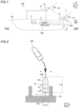
- FIGS. 1 to 9 The structure of a marine vessel 100 including a water area object detection system 103 according to preferred embodiments is now described with reference to FIGS. 1 to 9 .
- arrow FWD represents the forward movement direction of the marine vessel 100 (front side with reference to a hull 101)
- arrow BWD represents the reverse movement direction of the marine vessel 100 (rear side with reference to the hull 101).
- Arrow BWD also represents the imaging directions of a first imager 1a and a second imager 1b.
- a centerline ⁇ 1 of an imaging range A1 of the first imager 1a and a centerline ⁇ 2 of an imaging range A2 of the second imager 1b are parallel to arrow BWD.
- the centerline ⁇ 1 and the centerline ⁇ 2 are parallel to a centerline ⁇ (see FIG. 2 ) of the hull 101 in a right-left direction.
- arrow L represents the portside direction of the marine vessel 100 (left side with respect to the hull 101), and arrow R represents the starboard direction of the marine vessel 100 (right side with respect to the hull 101).
- a Z direction indicates an upward-downward direction.
- a Z1 direction indicates an upward direction.
- a Z2 direction indicates a downward direction.
- the marine vessel 100 includes the hull 101, a marine propulsion device 102 provided on the hull 101, and the water area object detection system 103 provided on or in the hull 101.
- the water area object detection system 103 includes the first imager 1a and the second imager 1b.
- the marine propulsion device 102 is attached to a stern (transom) T of the hull 101 from behind. That is, in preferred embodiments, the marine propulsion device 102 is an outboard motor, and the marine vessel 100 is an outboard motor boat.
- the overall length (length in a forward-rearward direction) L10 of the hull 101 shown in FIG. 2 is 20 m (about 65 feet) or less, which is relatively small.
- the hull 101 is a hull of a small marine vessel with an overall length L10 of about 8.7 m (about 28 feet), and is docked with a shore structure O1 positioned not to the left of the hull 101 but to the rear of the hull 101.
- the width L11 of the hull 101 is about 2.5 m.
- the water area object detection system 103 (controller 3) shown in FIG. 1 performs a control to estimate the self-position of the hull 101 in a water area map M while creating the two-dimensional water area map M (see FIG. 3 ) around the hull 101 that extends in a horizontal direction.
- the two-dimensional water area map M extends in the horizontal direction perpendicular to the upward-downward direction (Z direction) in which the first imager 1a and the second imager 1b are deviated from each other.
- control described above is achieved by simultaneous localization and mapping (SLAM).
- SLAM simultaneous localization and mapping
- the SLAM is a technique to simultaneously create an environment map around a mobile device and estimate the self-position of the mobile device in the environment map, using an image captured by a camera installed on the mobile device, for example.
- estimation of the self-position of the mobile device using the SLAM is able to be performed even in an environment such as indoors in which a GPS or the like is not usable.
- the SLAM enables the mobile device to move while avoiding surrounding objects so as to not collide with the objects, and to move along an optimal movement route without duplication of routes, for example.
- the SLAM includes passive SLAM (such as so-called visual SLAM) that uses an image sensor such as a camera to image a surrounding object, and active SLAM (such as so-called LiDAR SLAM) performed by irradiating a surrounding object with a laser beam of a laser device and detecting the reflected laser beam.
- passive SLAM such as so-called visual SLAM
- active SLAM such as so-called LiDAR SLAM
- the water area object detection system 103 performs a control using a technique such as the former passive SLAM.
- the marine vessel 100 performs a control to automatically move while avoiding obstacles (objects O) along a movement route r and a control to automatically dock the hull 101 at the shore structure O1 (see FIG. 2 ) such as a floating pier, using the water area map M created using the water area object detection system 103.
- the marine vessel 100 uses the water area map M as a way to know the positions of the obstacles (objects O) not only when the marine vessel 100 automatically moves but also when a user manually maneuvers the marine vessel 100. That is, the water area map M is a so-called cost map to indicate the positions of the obstacles (objects O) that are present around the marine vessel 100, for example.
- the water area object detection system 103 includes the first imager 1a, the second imager 1b, a display 2, and a controller 3.
- the first imager 1a, the second imager 1b, the display 2, and the controller 3 are provided on or in the hull 101.
- the water area object detection system 103 (controller 3) performs a control to create the water area map M in which an object presence range F1 including a likelihood that an object O is present is set around a feature point F by detecting, based on images captured by the first imager 1a and the second imager 1b, the feature point F corresponding to the object O in the images together with a distance to the feature point F.
- the first imager 1a and the second imager 1b shown in FIG. 1 capture images around the hull 101.
- the first imager 1a and the second imager 1b include monocular cameras including the same structure. That is, the second imager 1b is separate from the first imager 1a.
- the first imager 1a and the second imager 1b each include an imaging device such as a CCD sensor or a CMOS sensor.
- the first imager 1a and the second imager 1b are provided on the centerline ⁇ (see FIG. 2 ) of the hull 101 in the right-left direction in a plan view.
- the first imager 1a is provided at the stern (transom) T of the hull 101.
- the second imager 1b is provided on a roof R of the hull 101.
- the second imager 1b is provided on the hull 101 such that the imaging direction thereof is substantially the same as the imaging direction of the first imager 1a. Specifically, the first imager 1a and the second imager 1b image the rear (BWD) side of the hull 101 as the imaging directions.
- the second imager 1b is deviated in the upward-downward direction from the first imager 1a, and the first imager 1a is deviated in the imaging directions from the second imager 1b so as to not overlap the second imager 1b in the upward-downward direction perpendicular to the imaging directions.
- the second imager 1b is deviated in the upward direction from the first imager 1a, and is deviated in a forward direction from the first imager 1a.
- the rear end (the end on the first imager 1a side) of the second imager 1b is located forward of the front end (the end on the second imager 1b side) of the first imager 1a.
- the second imager 1b is deviated in the upward direction from the first imager 1a such that a range just in front of the second imager 1b in the imaging range A2 (a central portion of the image) of the second imager 1b is not restricted by the first imager 1a.
- the second imager 1b is located such that the first imager 1a fits within the imaging range A2 of the second imager 1b. That is, the second imager 1b is located such that the first imager 1a appears on the lower side of the image captured by the second imager 1b.
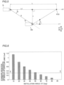
- the installation angle ⁇ (see FIG. 5 ) of the first imager 1a with respect to a horizontal plane and the second imager 1b is 50 degrees or less.
- the installation angle ⁇ of the first imager 1a with respect to the horizontal plane and the second imager 1b is 30 degrees. It is known from the viewpoint of epipolar constraints, which are geometric constraints, that as the installation angle ⁇ decreases, the angular dispersion of a plurality of acquired epipolar lines becomes larger, a measurement error of the distance to the feature point becomes smaller, and the positional accuracy of the water area map increases.
- FIG. 6 shows the results of calculating the standard deviation [rad] of the angles of a plurality of epipolar lines by fixing a distance in the horizontal direction between the first imager 1a and the second imager 1b shown in FIG. 5 at L1 and acquiring a plurality of epipolar lines for each of imager arrangements in which the installation angle ⁇ of the first imager 1a with respect to the horizontal plane and the second imager 1b is changed at intervals of 10 degrees up to 90 degrees.
- the standard deviation of the angles of the epipolar lines decreases.
- the standard deviation is larger than 0.3 when the installation angle ⁇ is 50 degrees or less. Cases in which the installation angle ⁇ shown in FIG. 6 is 60 to 90 degrees are Comparative Examples.
- a distance D between the first imager 1a and the second imager 1b is 2.0 m or less.
- the distance D between the first imager 1a and the second imager 1b is 1.5 m.
- a range in which the distance D is 2.0 m or less takes into consideration a structure in which the overall length L10 (see FIG. 2 ) of the hull 101 is 20 m (about 65 feet) or less.
- FIG. 7 shows Example of a preferred embodiment showing the epipolar lines in the image captured by the second imager 1b in a case in which the distance D between the first imager 1a and the second imager 1b is 1.5 m, and the installation angle ⁇ of the first imager 1a with respect to the horizontal plane and the second imager 1b is 30 degrees.
- FIG. 8 shows Comparative Example showing the epipolar lines in the image captured by the second imager in a case in which the first imager and the second imager are provided side by side in the right-left direction.
- the plurality of epipolar lines extend radially in the image of FIG. 7 .
- the plurality of epipolar lines extend in the right-left direction in the image of FIG. 8 .
- the water area object detection system 103 (controller 3) measures the distance to the feature point F using the first imager 1a and the second imager 1b. Specifically, the water area object detection system 103 (controller 3) measures the distance to the feature point F corresponding to the object O in an image captured by triangulation based on the images captured by the first imager 1a and the second imager 1b.
- the "feature point F corresponding to the object O in an image” refers to a specific point shown in a portion of the image in which the object O is located.
- the feature point F is set in a portion of the image in which there is a particularly large change in brightness or color tone.
- the water area object detection system 103 preliminarily performs distortion correction of the images captured by the first imager 1a and the second imager 1b, rectification to associate the images with each other, parallax estimation by matching corresponding feature points F on the images, and estimation of a relative position/relative orientation between the first imager 1a and the second imager 1b, for example, as preprocessing for distance measurement by the triangulation.
- a distance L in the horizontal direction from the second imager 1b to the feature point F (object O) is obtained by the following formula (1).
- the parallax d is a difference between the coordinates on the images of corresponding feature points of the images captured by the first imager 1a and the second imager 1b, and the unit is pixels.
- Mathematical Formula 1 L fx pd + L 1
- the second imager 1b is located with respect to the first imager 1a such that a target error ⁇ of a distance to the object O measured using the first imager 1a and the second imager 1b is 10 cm or less when the distance L to the object O imaged by the first imager 1a and the second imager 1b is 10 m or less.
- an area above a broken line shown in FIG. 9 satisfies the error conditions described above.
- the target error ⁇ is greater than 10 cm.
- the display 2 displays the water area map M created by the controller 3 (see FIG. 1 ).
- the display 2 displays the water area map M within a display image of 450 pixels wide by 600 pixels long.
- the display image of 450 pixels wide by 600 pixels long is a display image in which a point group is plotted in a world coordinate system.
- the size of one pixel of the water area map M corresponds to a size of 10 cm horizontally and 10 cm vertically in the world coordinate system.
- the display 2 displays the hull 101 on the water area map M.
- the display 2 displays a schematic model of the hull 101 on the water area map M.
- the display 2 displays the feature points F on the water area map M. Furthermore, the display 2 displays, on the water area map M, the object presence range F1 set around the feature point F and including a likelihood that the object O is present.
- the controller 3 performs a control to display one feature point F in one pixel of the display 2 and set a perfect circular object presence range F1 around one pixel P in which the feature point F is displayed to display the feature point F and the perfect circular object presence range F1 on the display 2.
- the object presence range F 1 has a circular shape with a smaller radius as it is closer to the hull 101.
- the object presence range F1 refers to a range set around the feature point F and including a likelihood that the object O is present.
- the object presence range F1 refers to a range in which the object O is probabilistically present. In other words, the object presence range F1 should be avoided when the marine vessel 100 moves, and a movement route for movement of the marine vessel 100 is not set in the object presence range F1.
- the display 2 displays an imaging area A with a predetermined angle of view indicating a range currently being imaged by the first imager 1a and the second imager 1b on the water area map M.
- the controller 3 shown in FIG. 1 includes a circuit board including a central processing unit (CPU), a read-only memory (ROM), a random access memory (RAM), etc., for example.
- the controller 3 is connected to the first imager 1a, the second imager 1b, the display 2, and the marine propulsion device 102 by signal lines.
- the controller 3 performs a control to automatically move the hull 101 by setting the movement route r for automatic movement based on the created water area map M (see FIG. 3 ) and controlling driving of the marine propulsion device 102.
- the controller 3 performs a control to create the water area map M in which the perfect circular object presence range F1 including a likelihood that the object O is present is set around the feature point F by detecting the feature point F corresponding to the object O in the images together with the distance to the feature point F based on the images captured by the first imager 1a and the second imager 1b.
- the controller 3 creates the two-dimensional water area map M extending in the horizontal direction around the hull 101 by setting the object presence range F1 in the horizontal plane perpendicular to the upward-downward direction (Z direction) in which the first imager 1a and the second imager 1b are deviated from each other.
- images were captured by changing the position of the first imager to positions 1 to 7 with respect to the fixed position of the second imager.
- the imaging directions of the first imager and the second imager are along arrow BWD.
- the positions 2 and 3 of the first imager are Examples, and the others (positions 1 and 4 to 7) are Comparative Examples.
- the first imager is located directly in front of the second imager.
- the first imager is located on the lower rear side within the angle of view of the second imager.
- the first imager is located on the lower rear side outside the angle of view of the second imager.
- the first imager is located directly below the second imager.
- the first imager is located on the rear left side within the angle of view of the second imager.
- the first imager is located on the rear left side outside the angle of view of the second imager.
- the first imager is located directly to the left within the angle of view of the second imager.
- FIG. 11 shows the variation of the relative orientation between the captured images at the position 7 of the first imager.
- Image numbers in FIG. 11 indicate the number of images captured in order.
- the yaw varies greatly between the images, and an error of the relative orientation in the captured images (an error of the relative orientation between the first imager and the second imager) is large.
- FIG. 12 shows the standard deviations [deg] of errors of the relative orientation for the pitch, yaw, and roll at each of the positions 1 to 7 of the first imager. It can be seen that the standard deviations [deg] of the errors of the relative orientation for all the pitch, yaw, and roll are small at the positions 1 to 3 of the first imager. On the other hand, it can be seen that the standard deviation [deg] of the errors of the relative orientation for any of the pitch, yaw, and roll is large at the positions 4 to 7 of the first imager.
- FIG. 13 shows the results of measuring the angular dispersion of the epipolar lines when a predetermined number of feature points are specified and a plurality of epipolar lines are acquired at each of the positions 1 to 7 of the first imager. At the positions 4 and 7 of the first imager, the plurality of epipolar lines become parallel lines extending vertically or horizontally on the image, and thus the dispersion becomes zero.
- a direction in which the first imager and the second imager are aligned coincides with a direction in which an object to be imaged (an object for which feature points are to be acquired) extends, and thus the plurality of epipolar lines extend horizontally on the image, and the dispersion becomes small.
- the direction in which the object to be imaged (the object for which feature points are to be acquired) extends refers to a horizontal direction in which a shore structure such as a pier extends.
- the position of the first imager is shifted from the position of the second imager in the imaging direction, and thus the dispersion becomes large.
- FIG. 14 shows the correlation between the error of the relative orientation between the captured images and the angular dispersion of the epipolar lines, together with a dashed power approximation curve.
- the coefficient of determination (R2) of the power approximation curve is 0.7049. In a range in which the dispersion is 0.3 or more, measurement points are generally located on the power approximation curve. Therefore, when the dispersion is at least 0.3 or more, the error of the relative orientation between the first imager and the second imager is maintained sufficiently small.
- the water area object detection system 103 includes the first imager 1a and the second imager 1b to image the object O around the hull 101, the second imager 1b is deviated in the upward-downward direction from the first imager 1a, and the first imager 1a is deviated in the imaging directions from the second imager 1b so as to not overlap the second imager 1b in the upward-downward direction perpendicular to the imaging directions.
- the angular dispersion of a plurality of epipolar lines becomes larger (an angular difference becomes larger) as compared with a case in which the two imagers are deviated from each other only in a direction perpendicular to the imaging direction, such as a transverse direction or an upward-downward direction. Therefore, with the structure as described above, the first imager 1b is deviated by a relatively large amount so as to not overlap the second imager 1b in the upward-downward direction perpendicular to the imaging directions in order to increase the angular dispersion of the plurality of epipolar lines.
- the positional accuracy of the water area map M created based on the images captured by the first imager 1a and the second imager 1b is improved.
- the second imager 1b is deviated in the upward-downward direction from the first imager 1a such that the imaging range just in front of the second imager 1b is prevented from being restricted by the first imager 1a.
- the first imager 1a and the second imager 1b are separate from each other, and thus their positions are freely adjusted.
- the first imager 1a and the second imager 1b are operable to image the rear side of the hull 101 as the imaging directions, and the second imager 1b is deviated in the upward direction from the first imager 1a, and is deviated in the forward direction from the first imager 1a. Accordingly, the first imager 1a is located below the second imager 1b in the imaging directions, and thus appearance of the first imager 1a and a structure to install the first imager 1a, for example, in the image captured by the second imager 1b is reduced or prevented.
- the first imager 1a and the second imager 1b are located at the stern T of the hull 101 and on the roof R of the hull 101, respectively. Accordingly, using the existing stern T and roof R, the first imager 1a and the second imager 1b are easily provided such that the first imager 1a is located below and behind the second imager 1b in the imaging directions.
- the second imager 1b is located such that the first imager 1a fits within the imaging range of the second imager 1b. Accordingly, the second imager 1b is prevented from being located such that the first imager 1a does not fit within the imaging range of the second imager 1b. That is, the second imager 1b is prevented from approaching an arrangement in which the second imager 1b is aligned with the first imager 1a in a transverse direction or the upward-downward direction perpendicular to the imaging directions. Therefore, the positional accuracy of the water area map M created based on the images captured by the first imager 1a and the second imager 1b is further improved.
- the installation angle of the first imager 1a with respect to the horizontal plane and the second imager 1b is 50 degrees or less. Accordingly, the installation angle of the first imager 1a with respect to the horizontal plane and the second imager 1b is limited to 50 degrees or less, and thus the second imager 1b is prevented from approaching an arrangement in which the second imager 1b is directly above the first imager 1a due to an excessive increase in the installation angle.
- the second imager 1b is prevented from approaching an arrangement in which the second imager 1b is in a direction perpendicular to the imaging directions, such as the transverse direction or the upward-downward direction (directly above), from the first imager 1a, and thus the angular dispersion of the plurality of epipolar lines is prevented from becoming small. Therefore, the positional accuracy of the water area map M created based on the images captured by the first imager 1a and the second imager 1b is still further improved.
- the controller 3 is configured or programmed to automatically dock the hull 101 by automatically moving the hull 101 toward the shore structure O1 corresponding to the object O imaged by the first imager 1a and the second imager 1b. Accordingly, the hull 101 is easily docked at the shore structure O1.
- the second imager 1b is located with respect to the first imager 1a such that the target error of the distance to the object O measured using the first imager 1a and the second imager 1b is 10 cm or less when the distance to the object O imaged by the first imager 1a and the second imager 1b is 10 m or less. Accordingly, the target error of the distance to the object O measured using the first imager 1a and the second imager 1b is maintained small, and thus the positional accuracy of the water area map created based on the images captured by the first imager 1a and the second imager 1b is further improved.
- the controller 3 is configured or programmed to create the two-dimensional water area map M extending in the horizontal direction perpendicular to the upward-downward direction in which the first imager 1a and the second imager 1b are deviated from each other. Accordingly, the processing load on the controller 3 is reduced as compared with a case in which a three-dimensional water area map M is created in consideration of the upward-downward direction (height direction).
- the distance between the first imager 1a and the second imager 1b is 2.0 m or less. Accordingly, the first imager 1a and the second imager 1b are relatively close to each other, and thus the first imager 1a and the second imager 1b are easily installed in the relatively small marine vessel 100.
- the controller 3 is configured or programmed to detect the feature point F corresponding to the object O in the images based on the images captured by the first imager 1a and the second imager 1b to create the water area map M in which the object presence range F1 including a likelihood that the object O is present is set around the feature point F. Accordingly, the object presence range F1 to be avoided by the marine vessel 100 is shown in the water area map M, and thus the object O around the hull 101 is easily known.
- the overall length L10 of the hull 101 is 20 m or less. Accordingly, in the relatively small marine vessel 100, the positional accuracy of the water area map M created based on the images captured by the first imager 1a and the second imager 1b is improved.
- the installation angle of the first imager with respect to the horizontal plane and the second imager is preferably 50 degrees or less in preferred embodiments described above, the present teaching is not restricted to this. In the present teaching, the installation angle of the first imager with respect to the horizontal plane and the second imager may alternatively be greater than 50 degrees.
- the distance between the first imager and the second imager is preferably 2.0 m or less in preferred embodiments described above, the present teaching is not restricted to this. In the present teaching, the distance between the first imager and the second imager may alternatively be greater than 2.0 m.
- the overall length of the hull is preferably 20 m or less in preferred embodiments described above, the present teaching is not restricted to this. In the present teaching, the overall length of the hull may alternatively be greater than 20 m.
- the marine vessel is preferably an outboard motor boat in preferred embodiments described above, the present teaching is not restricted to this.
- the marine vessel may alternatively be a marine vessel other than an outboard motor boat.
- the marine vessel may be a marine vessel including an inboard motor, an inboard-outboard motor, or a jet propulsion device.
- the object presence range is preferably indicated by a perfect circle in the water area map in preferred embodiments described above, the present teaching is not restricted to this.
- the object presence range may alternatively be indicated by a shape different from a perfect circle, such as an ellipse.
- the imaging direction of the first imager and the second imager is preferably set to the rear side of the hull in preferred embodiments described above, the present teaching is not restricted to this.
- the imaging direction of the first imager and the second imager may alternatively be different from the rear side of the hull, such as the front side, left side, or right side of the hull.
- the first imager is preferably provided at the stern of the hull in preferred embodiments described above, the present teaching is not restricted to this. In the present teaching, the first imager may alternatively be provided at a location different from the stern of the hull.
- the second imager is preferably provided on the roof of the hull in preferred embodiments described above, the present teaching is not restricted to this. In the present teaching, the second imager may alternatively be provided at a location different from the roof of the hull.
- first imager located on the rear side of the second imager which is the imaging direction
- first imager located on the rear side of the second imager which is the imaging direction
- present teaching is not restricted to this.
- first imager located on the rear side of the second imager, which is the imaging direction may alternatively be located above the second imager.
Landscapes
- Engineering & Computer Science (AREA)
- Radar, Positioning & Navigation (AREA)
- Remote Sensing (AREA)
- Physics & Mathematics (AREA)
- General Physics & Mathematics (AREA)
- Theoretical Computer Science (AREA)
- Multimedia (AREA)
- Automation & Control Theory (AREA)
- Combustion & Propulsion (AREA)
- Chemical & Material Sciences (AREA)
- Mechanical Engineering (AREA)
- Ocean & Marine Engineering (AREA)
- Aviation & Aerospace Engineering (AREA)
- Computer Vision & Pattern Recognition (AREA)
- Health & Medical Sciences (AREA)
- General Health & Medical Sciences (AREA)
- Vascular Medicine (AREA)
- Image Processing (AREA)
- Length Measuring Devices By Optical Means (AREA)
- Measurement Of Optical Distance (AREA)
Abstract
Description
- The present invention relates to a water area object detection system and a marine vessel with a water area object detection system, and more particularly, it relates to a water area object detection system including a plurality of imager provided on a hull to image the surroundings of the hull.
- A water area object detection system including a plurality of imager provided on a hull to image the surroundings of the hull is known in general. Such a water area object detection system is disclosed in
JP 2005-180949 A -
JP 2005-180949 A - Although not clearly described in
JP 2005-180949 A - When such a technique is applied to the automatic marine vessel docking system described in
JP 2005-180949 A - It is an object of the present invention to provide a water area object detection system and a marine vessel with a water area object detection system that can improve the positional accuracy of a water area map created based on images captured by a plurality of imagers. According to the present invention, said object is solved by a water area object detection system having the features of
independent claim 1. Preferred embodiments are laid down in the dependent claims. - A water area object detection system according to a preferred embodiment includes a first imager configured to be provided on a hull and configured to image an object around the hull, a second imager configured to be provided on the hull such that an imaging direction of the second imager is same as an imaging direction of the first imager and configured to image the object around the hull, and a controller configured or programmed to perform a control to create a water area map around the hull based on images captured by the first imager and the second imager. The second imager is configured to be deviated in an upward-downward direction of the hull from the first imager, and the first imager is configured to be deviated in the imaging directions from the second imager so as to not overlap the second imager in the upward-downward direction perpendicular to the imaging directions.
- A water area object detection system according to a preferred embodiment includes the first imager and the second imager to image the object around the hull, the second imager is deviated in the upward-downward direction from the first imager, and the first imager is deviated in the imaging directions from the second imager so as to not overlap the second imager in the upward-downward direction perpendicular to the imaging directions. In a technique to create a water area map using two imagers with the same imaging direction, when the two imagers are deviated from each other in the imaging direction, the angular dispersion of a plurality of epipolar lines becomes larger (an angular difference becomes larger) as compared with a case in which the two imagers are deviated from each other only in a direction perpendicular to the imaging direction, such as a transverse direction or an upward-downward direction. Therefore, with the structure as described above, the first imager is deviated by a relatively large amount so as to not overlap the second imager in the upward-downward direction perpendicular to the imaging directions in order to increase the angular dispersion of a plurality of epipolar lines. Consequently, the positional accuracy of the water area map created based on the images captured by the first imager and the second imager is improved. Furthermore, the second imager is deviated in the upward-downward direction from the first imager such that an imaging range just in front of the second imager is prevented from being restricted by the first imager.
- In a water area object detection system according to a preferred embodiment, the first imager and the second imager are preferably configured to image a rear side direction of the hull as the imaging directions, and the second imager is preferably configured to be deviated in an upward direction of the hull from the first imager, and is preferably configured to be deviated in a forward direction of the hull from the first imager. Accordingly, the first imager is located below the second imager in the imaging directions, and thus appearance of the first imager and a structure to install the first imager, for example, in the image captured by the second imager is reduced or prevented.
- In such a case, the first imager and the second imager are preferably configured to be located at a stern of the hull and on a roof of the hull, respectively. Accordingly, using the existing stern and roof, the first imager and the second imager are easily provided such that the first imager is located below and behind the second imager in the imaging directions.
- In a water area object detection system according to a preferred embodiment, the second imager is preferably configured to be located such that the first imager fits within an imaging range of the second imager. Accordingly, the second imager is prevented from being located such that the first imager does not fit within the imaging range of the second imager. That is, the second imager is prevented from approaching an arrangement in which the second imager is aligned with the first imager in a transverse direction or the upward-downward direction perpendicular to the imaging directions. Therefore, the positional accuracy of the water area map created based on the images captured by the first imager and the second imager is further improved.
- In such a case, the first imager is preferably configured to have an installation angle of 50 degrees or less with respect to a horizontal plane and the second imager. Accordingly, the installation angle of the first imager with respect to the horizontal plane and the second imager is limited to 50 degrees or less, and thus the second imager is prevented from approaching an arrangement in which the second imager is directly above the first imager due to an excessive increase in the installation angle. In other words, the second imager is prevented from approaching an arrangement in which the second imager is in a direction perpendicular to the imaging directions, such as the transverse direction or the upward-downward direction (directly above), from the first imager, and thus the angular dispersion of the plurality of epipolar lines is prevented from becoming small. Therefore, the positional accuracy of the water area map created based on the images captured by the first imager and the second imager is still further improved.
- In a water area object detection system according to a preferred embodiment, the controller is preferably configured or programmed to automatically dock the hull by automatically moving the hull toward a shore structure corresponding to the object imaged by the first imager and the second imager. Accordingly, the hull is easily docked at the shore structure.
- In a water area object detection system according to a preferred embodiment, the second imager is preferably configured to be located with respect to the first imager such that a target error of a distance to the object measured using the first imager and the second imager is 10 cm or less when the distance to the object imaged by the first imager and the second imager is 10 m or less. Accordingly, the target error of the distance to the object measured using the first imager and the second imager is maintained small, and thus the positional accuracy of the water area map created based on the images captured by the first imager and the second imager is further improved.
- In a water area object detection system according to a preferred embodiment, the controller is preferably configured or programmed to create the two-dimensional water area map to be extending in a horizontal direction perpendicular to the upward-downward direction in which the first imager and the second imager are deviated from each other. Accordingly, the processing load on the controller is reduced as compared with a case in which a three-dimensional water area map is created in consideration of the upward-downward direction (height direction).
- In a water area object detection system according to a preferred embodiment, a distance between the first imager and the second imager is preferably 2.0 m or less. Accordingly, the first imager and the second imager are relatively close to each other, and thus the first imager and the second imager are easily installed in a relatively small marine vessel.
- In a water area object detection system according to a preferred embodiment, the controller is preferably configured or programmed to detect a feature point corresponding to the object in images based on the images captured by the first imager and the second imager to create the water area map in which an object presence range including a likelihood that the object is present is set around the feature point. Accordingly, the object presence range to be avoided by a marine vessel is shown in the water area map, and thus the object around the hull is easily known.
- The above and other elements, features, steps, characteristics and advantages of preferred embodiments will become more apparent from the following detailed description of the preferred embodiments with reference to the attached drawings.
-
-
FIG. 1 is a side view showing a marine vessel including a water area object detection system according to a preferred embodiment. -
FIG. 2 is a plan view illustrating docking of a marine vessel at a shore structure according to a preferred embodiment. -
FIG. 3 is a diagram showing a water area map created by a water area object detection system according to a preferred embodiment. -
FIG. 4 is a schematic view illustrating the sizes of object presence ranges on a water area map created by a water area object detection system according to a preferred embodiment. -
FIG. 5 is a diagram illustrating triangulation using a first imager and a second imager of a water area object detection system according to a preferred embodiment. -
FIG. 6 is a graph showing a relationship between the installation angle (θ) of a first imager with respect to a horizontal plane and a second imager and the standard deviation of the angles of epipolar lines. -
FIG. 7 is a diagram illustrating Example in which epipolar lines are shown in an image captured by a second imager when a first imager and the second imager are deviated in an imaging direction. -
FIG. 8 is a diagram illustrating Comparative Example in which epipolar lines are shown in an image captured by a second imager when a first imager and the second imager are located side by side. -
FIG. 9 is a graph showing a relationship between the installation angle (θ) of a first imager with respect to a horizontal plane and a second imager and a distance (D) between the first imager and the second imager. -
FIG. 10 is a diagram illustrating arrangements of a first imager with respect to a second imager in Examples (2 and 3) and Comparative Examples (1 and 4 to 7). -
FIG. 11 is a graph showing changes in a relative orientation between captured images when a plurality of images are captured with a first imager and a second imager located at a predetermined position. -
FIG. 12 is a graph showing a relationship between arrangements of a first imager with respect to a second imager and the standard variation of errors of a relative orientation between captured images. -
FIG. 13 is a graph showing a relationship between arrangements of a first imager with respect to a second imager and the angular dispersion of epipolar lines. -
FIG. 14 is a graph showing a relationship between the angular dispersion of epipolar lines and errors of a relative orientation between captured images. - Preferred embodiments are hereinafter described with reference to the drawings.
- The structure of a
marine vessel 100 including a water areaobject detection system 103 according to preferred embodiments is now described with reference toFIGS. 1 to 9 . - In the figures, arrow FWD represents the forward movement direction of the marine vessel 100 (front side with reference to a hull 101), and arrow BWD represents the reverse movement direction of the marine vessel 100 (rear side with reference to the hull 101). Arrow BWD also represents the imaging directions of a
first imager 1a and asecond imager 1b. A centerline α1 of an imaging range A1 of thefirst imager 1a and a centerline α2 of an imaging range A2 of thesecond imager 1b are parallel to arrow BWD. Furthermore, the centerline α1 and the centerline α2 are parallel to a centerline β (seeFIG. 2 ) of thehull 101 in a right-left direction. - In the figures, arrow L represents the portside direction of the marine vessel 100 (left side with respect to the hull 101), and arrow R represents the starboard direction of the marine vessel 100 (right side with respect to the hull 101).
- In the figures, a Z direction indicates an upward-downward direction. A Z1 direction indicates an upward direction. A Z2 direction indicates a downward direction.
- As shown in
FIG. 1 , themarine vessel 100 includes thehull 101, amarine propulsion device 102 provided on thehull 101, and the water areaobject detection system 103 provided on or in thehull 101. The water areaobject detection system 103 includes thefirst imager 1a and thesecond imager 1b. - The
marine propulsion device 102 is attached to a stern (transom) T of thehull 101 from behind. That is, in preferred embodiments, themarine propulsion device 102 is an outboard motor, and themarine vessel 100 is an outboard motor boat. - The overall length (length in a forward-rearward direction) L10 of the
hull 101 shown inFIG. 2 is 20 m (about 65 feet) or less, which is relatively small. As an example, thehull 101 is a hull of a small marine vessel with an overall length L10 of about 8.7 m (about 28 feet), and is docked with a shore structure O1 positioned not to the left of thehull 101 but to the rear of thehull 101. As an example, the width L11 of thehull 101 is about 2.5 m. - The water area object detection system 103 (controller 3) shown in
FIG. 1 performs a control to estimate the self-position of thehull 101 in a water area map M while creating the two-dimensional water area map M (seeFIG. 3 ) around thehull 101 that extends in a horizontal direction. The two-dimensional water area map M extends in the horizontal direction perpendicular to the upward-downward direction (Z direction) in which thefirst imager 1a and thesecond imager 1b are deviated from each other. - As an example, the control described above (the control to estimate the self-position of the
hull 101 in the water area map M while creating the water area map M) is achieved by simultaneous localization and mapping (SLAM). - The SLAM is a technique to simultaneously create an environment map around a mobile device and estimate the self-position of the mobile device in the environment map, using an image captured by a camera installed on the mobile device, for example. Unlike estimation of a self-position on a map using a global positioning system (GPS), for example, estimation of the self-position of the mobile device using the SLAM is able to be performed even in an environment such as indoors in which a GPS or the like is not usable.
- The SLAM enables the mobile device to move while avoiding surrounding objects so as to not collide with the objects, and to move along an optimal movement route without duplication of routes, for example.
- The SLAM includes passive SLAM (such as so-called visual SLAM) that uses an image sensor such as a camera to image a surrounding object, and active SLAM (such as so-called LiDAR SLAM) performed by irradiating a surrounding object with a laser beam of a laser device and detecting the reflected laser beam. The water area
object detection system 103 according to preferred embodiments performs a control using a technique such as the former passive SLAM. - As shown in
FIGS. 3 and 4 , themarine vessel 100 performs a control to automatically move while avoiding obstacles (objects O) along a movement route r and a control to automatically dock thehull 101 at the shore structure O1 (seeFIG. 2 ) such as a floating pier, using the water area map M created using the water areaobject detection system 103. - The
marine vessel 100 uses the water area map M as a way to know the positions of the obstacles (objects O) not only when themarine vessel 100 automatically moves but also when a user manually maneuvers themarine vessel 100. That is, the water area map M is a so-called cost map to indicate the positions of the obstacles (objects O) that are present around themarine vessel 100, for example. - As shown in
FIG. 1 , the water areaobject detection system 103 includes thefirst imager 1a, thesecond imager 1b, adisplay 2, and acontroller 3. Thefirst imager 1a, thesecond imager 1b, thedisplay 2, and thecontroller 3 are provided on or in thehull 101. - As shown in
FIG. 4 , the water area object detection system 103 (controller 3) performs a control to create the water area map M in which an object presence range F1 including a likelihood that an object O is present is set around a feature point F by detecting, based on images captured by thefirst imager 1a and thesecond imager 1b, the feature point F corresponding to the object O in the images together with a distance to the feature point F. - The
first imager 1a and thesecond imager 1b shown inFIG. 1 capture images around thehull 101. Thefirst imager 1a and thesecond imager 1b include monocular cameras including the same structure. That is, thesecond imager 1b is separate from thefirst imager 1a. Thefirst imager 1a and thesecond imager 1b each include an imaging device such as a CCD sensor or a CMOS sensor. Thefirst imager 1a and thesecond imager 1b are provided on the centerline β (seeFIG. 2 ) of thehull 101 in the right-left direction in a plan view. - The
first imager 1a is provided at the stern (transom) T of thehull 101. Thesecond imager 1b is provided on a roof R of thehull 101. - The
second imager 1b is provided on thehull 101 such that the imaging direction thereof is substantially the same as the imaging direction of thefirst imager 1a. Specifically, thefirst imager 1a and thesecond imager 1b image the rear (BWD) side of thehull 101 as the imaging directions. - The
second imager 1b is deviated in the upward-downward direction from thefirst imager 1a, and thefirst imager 1a is deviated in the imaging directions from thesecond imager 1b so as to not overlap thesecond imager 1b in the upward-downward direction perpendicular to the imaging directions. Specifically, thesecond imager 1b is deviated in the upward direction from thefirst imager 1a, and is deviated in a forward direction from thefirst imager 1a. The rear end (the end on thefirst imager 1a side) of thesecond imager 1b is located forward of the front end (the end on thesecond imager 1b side) of thefirst imager 1a. Thus, thesecond imager 1b is deviated in the upward direction from thefirst imager 1a such that a range just in front of thesecond imager 1b in the imaging range A2 (a central portion of the image) of thesecond imager 1b is not restricted by thefirst imager 1a. - The
second imager 1b is located such that thefirst imager 1a fits within the imaging range A2 of thesecond imager 1b. That is, thesecond imager 1b is located such that thefirst imager 1a appears on the lower side of the image captured by thesecond imager 1b. - The installation angle θ (see
FIG. 5 ) of thefirst imager 1a with respect to a horizontal plane and thesecond imager 1b is 50 degrees or less. As an example, the installation angle θ of thefirst imager 1a with respect to the horizontal plane and thesecond imager 1b is 30 degrees. It is known from the viewpoint of epipolar constraints, which are geometric constraints, that as the installation angle θ decreases, the angular dispersion of a plurality of acquired epipolar lines becomes larger, a measurement error of the distance to the feature point becomes smaller, and the positional accuracy of the water area map increases. - As an example,
FIG. 6 shows the results of calculating the standard deviation [rad] of the angles of a plurality of epipolar lines by fixing a distance in the horizontal direction between thefirst imager 1a and thesecond imager 1b shown inFIG. 5 at L1 and acquiring a plurality of epipolar lines for each of imager arrangements in which the installation angle θ of thefirst imager 1a with respect to the horizontal plane and thesecond imager 1b is changed at intervals of 10 degrees up to 90 degrees. As the installation angle θ decreases, the standard deviation of the angles of the epipolar lines decreases. In Example, the standard deviation is larger than 0.3 when the installation angle θ is 50 degrees or less. Cases in which the installation angle θ shown inFIG. 6 is 60 to 90 degrees are Comparative Examples. - A distance D between the
first imager 1a and thesecond imager 1b is 2.0 m or less. As an example, the distance D between thefirst imager 1a and thesecond imager 1b is 1.5 m. A range in which the distance D is 2.0 m or less takes into consideration a structure in which the overall length L10 (seeFIG. 2 ) of thehull 101 is 20 m (about 65 feet) or less. -
FIG. 7 shows Example of a preferred embodiment showing the epipolar lines in the image captured by thesecond imager 1b in a case in which the distance D between thefirst imager 1a and thesecond imager 1b is 1.5 m, and the installation angle θ of thefirst imager 1a with respect to the horizontal plane and thesecond imager 1b is 30 degrees.FIG. 8 shows Comparative Example showing the epipolar lines in the image captured by the second imager in a case in which the first imager and the second imager are provided side by side in the right-left direction. The plurality of epipolar lines extend radially in the image ofFIG. 7 . The plurality of epipolar lines extend in the right-left direction in the image ofFIG. 8 . - The water area object detection system 103 (controller 3) measures the distance to the feature point F using the
first imager 1a and thesecond imager 1b. Specifically, the water area object detection system 103 (controller 3) measures the distance to the feature point F corresponding to the object O in an image captured by triangulation based on the images captured by thefirst imager 1a and thesecond imager 1b. - The "feature point F corresponding to the object O in an image" refers to a specific point shown in a portion of the image in which the object O is located. As an example, the feature point F is set in a portion of the image in which there is a particularly large change in brightness or color tone.
- The water area object detection system 103 (controller 3) preliminarily performs distortion correction of the images captured by the
first imager 1a and thesecond imager 1b, rectification to associate the images with each other, parallax estimation by matching corresponding feature points F on the images, and estimation of a relative position/relative orientation between thefirst imager 1a and thesecond imager 1b, for example, as preprocessing for distance measurement by the triangulation. - Measurement of the distance to the feature point F by the triangulation performed by the water area object detection system 103 (controller 3) is now described with reference to
FIG. 5 . - Assuming that L1 represents the distance in a horizontal direction (imaging directions) between the
first imager 1a and thesecond imager 1b as described above, x represents a distance in the upward-downward direction between thefirst imager 1a and thesecond imager 1b, d represents the parallax of thefirst imager 1a and thesecond imager 1b, p represents the element pitch of the imaging device of thefirst imager 1a (second imager 1b), and f represents a focal length of thefirst imager 1a (second imager 1b), a distance L in the horizontal direction from thesecond imager 1b to the feature point F (object O) is obtained by the following formula (1). The parallax d is a difference between the coordinates on the images of corresponding feature points of the images captured by thefirst imager 1a and thesecond imager 1b, and the unit is pixels.
Mathematical Formula 1
- The
second imager 1b is located with respect to thefirst imager 1a such that a target error δ of a distance to the object O measured using thefirst imager 1a and thesecond imager 1b is 10 cm or less when the distance L to the object O imaged by thefirst imager 1a and thesecond imager 1b is 10 m or less. The target error δ is an estimated distance resolution determined by the resolution of the parallax d near the distance L = 10 m. Assuming that the unit of the resolution of the parallax d is 1 pixel, and da and db represent the parallaxes of two imagers (da = 10 pixels and db = 11 pixels, for example), the resolution of the distance L, i.e., the target error δ (the unit is [m]) is obtained by the following formula (2).
Mathematical Formula 2
- Considering the relationship between the linear distance D between the
first imager 1a and thesecond imager 1b and the installation angle θ of thefirst imager 1a with respect to the horizontal plane and thesecond imager 1b so as to satisfy the error conditions described above, an area above a broken line shown inFIG. 9 satisfies the error conditions described above. In an area below the broken line, the target error δ is greater than 10 cm. - When the installation angle θ is set to 50 degrees or less and the distance D is set to 2.0 m or less under the error conditions described above, a hatched area in
FIG. 9 satisfies the error conditions described above. - As shown in
FIGS. 3 and 4 , the display 2 (seeFIG. 1 ) displays the water area map M created by the controller 3 (seeFIG. 1 ). As an example, thedisplay 2 displays the water area map M within a display image of 450 pixels wide by 600 pixels long. The display image of 450 pixels wide by 600 pixels long is a display image in which a point group is plotted in a world coordinate system. As an example, the size of one pixel of the water area map M corresponds to a size of 10 cm horizontally and 10 cm vertically in the world coordinate system. - The
display 2 displays thehull 101 on the water area map M. Thedisplay 2 displays a schematic model of thehull 101 on the water area map M. - The
display 2 displays the feature points F on the water area map M. Furthermore, thedisplay 2 displays, on the water area map M, the object presence range F1 set around the feature point F and including a likelihood that the object O is present. As a specific example, thecontroller 3 performs a control to display one feature point F in one pixel of thedisplay 2 and set a perfect circular object presence range F1 around one pixel P in which the feature point F is displayed to display the feature point F and the perfect circular object presence range F1 on thedisplay 2. The objectpresence range F 1 has a circular shape with a smaller radius as it is closer to thehull 101. - The object presence range F1 refers to a range set around the feature point F and including a likelihood that the object O is present. In short, the object presence range F1 refers to a range in which the object O is probabilistically present. In other words, the object presence range F1 should be avoided when the
marine vessel 100 moves, and a movement route for movement of themarine vessel 100 is not set in the object presence range F1. - The
display 2 displays an imaging area A with a predetermined angle of view indicating a range currently being imaged by thefirst imager 1a and thesecond imager 1b on the water area map M. - The
controller 3 shown inFIG. 1 includes a circuit board including a central processing unit (CPU), a read-only memory (ROM), a random access memory (RAM), etc., for example. Thecontroller 3 is connected to thefirst imager 1a, thesecond imager 1b, thedisplay 2, and themarine propulsion device 102 by signal lines. - The
controller 3 performs a control to automatically move thehull 101 by setting the movement route r for automatic movement based on the created water area map M (seeFIG. 3 ) and controlling driving of themarine propulsion device 102. - The
controller 3 performs a control to create the water area map M in which the perfect circular object presence range F1 including a likelihood that the object O is present is set around the feature point F by detecting the feature point F corresponding to the object O in the images together with the distance to the feature point F based on the images captured by thefirst imager 1a and thesecond imager 1b. - The
controller 3 creates the two-dimensional water area map M extending in the horizontal direction around thehull 101 by setting the object presence range F1 in the horizontal plane perpendicular to the upward-downward direction (Z direction) in which thefirst imager 1a and thesecond imager 1b are deviated from each other. - Examples and Comparative Examples regarding the correlation between the angular dispersion of the epipolar lines and errors in the captured images are now described with reference to
FIGS. 10 to 14 . - As shown in
FIG. 10 , images were captured by changing the position of the first imager topositions 1 to 7 with respect to the fixed position of the second imager. The imaging directions of the first imager and the second imager are along arrow BWD. Thepositions positions - At the
position 1, the first imager is located directly in front of the second imager. At theposition 2, the first imager is located on the lower rear side within the angle of view of the second imager. At theposition 3, the first imager is located on the lower rear side outside the angle of view of the second imager. At theposition 4, the first imager is located directly below the second imager. At theposition 5, the first imager is located on the rear left side within the angle of view of the second imager. At theposition 6, the first imager is located on the rear left side outside the angle of view of the second imager. At theposition 7, the first imager is located directly to the left within the angle of view of the second imager. - Then, for each of the
positions 1 to 7 of the first imager, a predetermined number of images (eleven, for example) were captured, and a relative orientation [deg] including a pitch angle, a yaw angle, and a roll angle between the first imager and the second imager was estimated from the captured images. As an example,FIG. 11 shows the variation of the relative orientation between the captured images at theposition 7 of the first imager. Image numbers inFIG. 11 indicate the number of images captured in order. InFIG. 11 , it can be seen that the yaw varies greatly between the images, and an error of the relative orientation in the captured images (an error of the relative orientation between the first imager and the second imager) is large. InFIG. 11 , it is ideal that all of the pitch, yaw, and roll extend in a straight line in the lateral direction, because the error of the relative orientation in the images becomes small. -
FIG. 12 shows the standard deviations [deg] of errors of the relative orientation for the pitch, yaw, and roll at each of thepositions 1 to 7 of the first imager. It can be seen that the standard deviations [deg] of the errors of the relative orientation for all the pitch, yaw, and roll are small at thepositions 1 to 3 of the first imager. On the other hand, it can be seen that the standard deviation [deg] of the errors of the relative orientation for any of the pitch, yaw, and roll is large at thepositions 4 to 7 of the first imager. -
FIG. 13 shows the results of measuring the angular dispersion of the epipolar lines when a predetermined number of feature points are specified and a plurality of epipolar lines are acquired at each of thepositions 1 to 7 of the first imager. At thepositions - At the
positions positions 1 to 3 of the first imager, the position of the first imager is shifted from the position of the second imager in the imaging direction, and thus the dispersion becomes large. -
FIG. 14 shows the correlation between the error of the relative orientation between the captured images and the angular dispersion of the epipolar lines, together with a dashed power approximation curve. The coefficient of determination (R2) of the power approximation curve is 0.7049. In a range in which the dispersion is 0.3 or more, measurement points are generally located on the power approximation curve. Therefore, when the dispersion is at least 0.3 or more, the error of the relative orientation between the first imager and the second imager is maintained sufficiently small. - According to the various preferred embodiments described above, the following advantageous effects are achieved.
- According to a preferred embodiment, the water area
object detection system 103 includes thefirst imager 1a and thesecond imager 1b to image the object O around thehull 101, thesecond imager 1b is deviated in the upward-downward direction from thefirst imager 1a, and thefirst imager 1a is deviated in the imaging directions from thesecond imager 1b so as to not overlap thesecond imager 1b in the upward-downward direction perpendicular to the imaging directions. In a technique to create a water area map using two imagers with the same imaging direction, when the two imagers are deviated from each other in the imaging direction, the angular dispersion of a plurality of epipolar lines becomes larger (an angular difference becomes larger) as compared with a case in which the two imagers are deviated from each other only in a direction perpendicular to the imaging direction, such as a transverse direction or an upward-downward direction. Therefore, with the structure as described above, thefirst imager 1b is deviated by a relatively large amount so as to not overlap thesecond imager 1b in the upward-downward direction perpendicular to the imaging directions in order to increase the angular dispersion of the plurality of epipolar lines. Consequently, the positional accuracy of the water area map M created based on the images captured by thefirst imager 1a and thesecond imager 1b is improved. Furthermore, thesecond imager 1b is deviated in the upward-downward direction from thefirst imager 1a such that the imaging range just in front of thesecond imager 1b is prevented from being restricted by thefirst imager 1a. Moreover, thefirst imager 1a and thesecond imager 1b are separate from each other, and thus their positions are freely adjusted. - According to a preferred embodiment, the
first imager 1a and thesecond imager 1b are operable to image the rear side of thehull 101 as the imaging directions, and thesecond imager 1b is deviated in the upward direction from thefirst imager 1a, and is deviated in the forward direction from thefirst imager 1a. Accordingly, thefirst imager 1a is located below thesecond imager 1b in the imaging directions, and thus appearance of thefirst imager 1a and a structure to install thefirst imager 1a, for example, in the image captured by thesecond imager 1b is reduced or prevented. - According to a preferred embodiment, the
first imager 1a and thesecond imager 1b are located at the stern T of thehull 101 and on the roof R of thehull 101, respectively. Accordingly, using the existing stern T and roof R, thefirst imager 1a and thesecond imager 1b are easily provided such that thefirst imager 1a is located below and behind thesecond imager 1b in the imaging directions. - According to a preferred embodiment, the
second imager 1b is located such that thefirst imager 1a fits within the imaging range of thesecond imager 1b. Accordingly, thesecond imager 1b is prevented from being located such that thefirst imager 1a does not fit within the imaging range of thesecond imager 1b. That is, thesecond imager 1b is prevented from approaching an arrangement in which thesecond imager 1b is aligned with thefirst imager 1a in a transverse direction or the upward-downward direction perpendicular to the imaging directions. Therefore, the positional accuracy of the water area map M created based on the images captured by thefirst imager 1a and thesecond imager 1b is further improved. - According to a preferred embodiment, the installation angle of the
first imager 1a with respect to the horizontal plane and thesecond imager 1b is 50 degrees or less. Accordingly, the installation angle of thefirst imager 1a with respect to the horizontal plane and thesecond imager 1b is limited to 50 degrees or less, and thus thesecond imager 1b is prevented from approaching an arrangement in which thesecond imager 1b is directly above thefirst imager 1a due to an excessive increase in the installation angle. In other words, thesecond imager 1b is prevented from approaching an arrangement in which thesecond imager 1b is in a direction perpendicular to the imaging directions, such as the transverse direction or the upward-downward direction (directly above), from thefirst imager 1a, and thus the angular dispersion of the plurality of epipolar lines is prevented from becoming small. Therefore, the positional accuracy of the water area map M created based on the images captured by thefirst imager 1a and thesecond imager 1b is still further improved. - According to a preferred embodiment, the
controller 3 is configured or programmed to automatically dock thehull 101 by automatically moving thehull 101 toward the shore structure O1 corresponding to the object O imaged by thefirst imager 1a and thesecond imager 1b. Accordingly, thehull 101 is easily docked at the shore structure O1. - According to a preferred embodiment, the
second imager 1b is located with respect to thefirst imager 1a such that the target error of the distance to the object O measured using thefirst imager 1a and thesecond imager 1b is 10 cm or less when the distance to the object O imaged by thefirst imager 1a and thesecond imager 1b is 10 m or less. Accordingly, the target error of the distance to the object O measured using thefirst imager 1a and thesecond imager 1b is maintained small, and thus the positional accuracy of the water area map created based on the images captured by thefirst imager 1a and thesecond imager 1b is further improved. - According to a preferred embodiment, the
controller 3 is configured or programmed to create the two-dimensional water area map M extending in the horizontal direction perpendicular to the upward-downward direction in which thefirst imager 1a and thesecond imager 1b are deviated from each other. Accordingly, the processing load on thecontroller 3 is reduced as compared with a case in which a three-dimensional water area map M is created in consideration of the upward-downward direction (height direction). - According to a preferred embodiment, the distance between the
first imager 1a and thesecond imager 1b is 2.0 m or less. Accordingly, thefirst imager 1a and thesecond imager 1b are relatively close to each other, and thus thefirst imager 1a and thesecond imager 1b are easily installed in the relatively smallmarine vessel 100. - According to a preferred embodiment, the
controller 3 is configured or programmed to detect the feature point F corresponding to the object O in the images based on the images captured by thefirst imager 1a and thesecond imager 1b to create the water area map M in which the object presence range F1 including a likelihood that the object O is present is set around the feature point F. Accordingly, the object presence range F1 to be avoided by themarine vessel 100 is shown in the water area map M, and thus the object O around thehull 101 is easily known. - According to a preferred embodiment, the overall length L10 of the
hull 101 is 20 m or less. Accordingly, in the relatively smallmarine vessel 100, the positional accuracy of the water area map M created based on the images captured by thefirst imager 1a and thesecond imager 1b is improved. - The preferred embodiments described above are illustrative for present teaching but the present teaching also relates to modifications of the preferred embodiments.
- For example, while the installation angle of the first imager with respect to the horizontal plane and the second imager is preferably 50 degrees or less in preferred embodiments described above, the present teaching is not restricted to this. In the present teaching, the installation angle of the first imager with respect to the horizontal plane and the second imager may alternatively be greater than 50 degrees.
- While the distance between the first imager and the second imager is preferably 2.0 m or less in preferred embodiments described above, the present teaching is not restricted to this. In the present teaching, the distance between the first imager and the second imager may alternatively be greater than 2.0 m.
- While the overall length of the hull is preferably 20 m or less in preferred embodiments described above, the present teaching is not restricted to this. In the present teaching, the overall length of the hull may alternatively be greater than 20 m.
- While the marine vessel is preferably an outboard motor boat in preferred embodiments described above, the present teaching is not restricted to this. In the present teaching, the marine vessel may alternatively be a marine vessel other than an outboard motor boat. For example, the marine vessel may be a marine vessel including an inboard motor, an inboard-outboard motor, or a jet propulsion device.
- While the object presence range is preferably indicated by a perfect circle in the water area map in preferred embodiments described above, the present teaching is not restricted to this. In the present teaching, the object presence range may alternatively be indicated by a shape different from a perfect circle, such as an ellipse.
- While the imaging direction of the first imager and the second imager is preferably set to the rear side of the hull in preferred embodiments described above, the present teaching is not restricted to this. In the present teaching, the imaging direction of the first imager and the second imager may alternatively be different from the rear side of the hull, such as the front side, left side, or right side of the hull.
- While the first imager is preferably provided at the stern of the hull in preferred embodiments described above, the present teaching is not restricted to this. In the present teaching, the first imager may alternatively be provided at a location different from the stern of the hull.
- While the second imager is preferably provided on the roof of the hull in preferred embodiments described above, the present teaching is not restricted to this. In the present teaching, the second imager may alternatively be provided at a location different from the roof of the hull.
- While the first imager located on the rear side of the second imager, which is the imaging direction, is preferably located below the second imager in preferred embodiments described above, the present teaching is not restricted to this. In the present teaching, the first imager located on the rear side of the second imager, which is the imaging direction, may alternatively be located above the second imager.
Claims (11)
- A water area object detection system (103) for a marine vessel (100) having a hull (101), the system comprising:a first imager (1a) configured to be provided on the hull (101) and configured to image an object (O) around the hull (101);a second imager (1b) configured to be provided on the hull (101) such that an imaging direction of the second imager (1b) is same as an imaging direction of the first imager (1a) and configured to image the object (O) around the hull (101); anda controller (3) configured or programmed to perform a control to create a water area map (M) around the hull (101) based on images captured by the first imager (1a) and the second imager (1b); whereinthe second imager (1b) is configured to be deviated in an upward-downward direction (Z) of the hull (101) from the first imager (1a); andthe first imager (1a) is configured to be deviated in the imaging directions from the second imager (1b) so as to not overlap the second imager (1b) in the upward-downward direction (Z) perpendicular to the imaging directions.
- The water area object detection system (103) according to claim 1, wherein the first imager (1a) and the second imager (1b) are configured to image a rear side direction of the hull (101) as the imaging directions; and
the second imager (1b) is configured to be deviated in an upward direction (Z1) of the hull (101) from the first imager (1a), and is configured to be deviated in a forward direction of the hull (101) from the first imager (1a). - The water area object detection system (103) according to claim 2, wherein the first imager (1a) is configured to be located at a stern (T) of the hull (101) and the second imager (1b) is configured to be located on a roof (R) of the hull (101).
- The water area object detection system (103) according to any one of claims 1 to 3, wherein the second imager (1b) is configured to be located such that the first imager (1a) fits within an imaging range (A2) of the second imager (1b).
- The water area object detection system (103) according to claim 4, wherein the first imager (1a) is configured to have an installation angle (θ) of 50 degrees or less with respect to a horizontal plane of the hull (101) and the second imager (1b).
- The water area object detection system (103) according to any one of claims 1 to 5, wherein the controller (3) is configured or programmed to control automatically docking the hull (101) by controlling automatically moving the hull (101) toward a shore structure (O1) corresponding to the object (O) imaged by the first imager (1a) and the second imager (1b).
- The water area object detection system (103) according to any one of claims 1 to 6, wherein the second imager (1b) is configured to be located with respect to the first imager (1a) such that a target error (δ) of a distance to the object (O) measured using the first imager (1a) and the second imager (1b) is 10 cm or less when the distance to the object (O) imaged by the first imager (1a) and the second imager (1b) is 10 m or less.
- The water area object detection system (103) according to any one of claims 1 to 7, wherein the controller (3) is configured or programmed to create the two-dimensional water area map (M) to be extending in a horizontal direction perpendicular to the upward-downward direction of the hull (101) in which the first imager (1a) and the second imager (1b) are deviated from each other.
- The water area object detection system (103) according to any one of claims 1 to 8, wherein a distance (D) between the first imager (1a) and the second imager (1b) is 2.0 m or less.
- The water area object detection system (103) according to any one of claims 1 to 9, wherein the controller (3) is configured or programmed to detect a feature point (F) corresponding to the object (O) in images based on the images captured by the first imager (1a) and the second imager (1b) to create the water area map (M) in which an object presence range (F1) including a likelihood that the object (O) is present is set around the feature point (F).
- A marine vessel (100) having a hull (101) and a water area object detection system (103) according to any one of claims 1 to 10.
Applications Claiming Priority (1)
| Application Number | Priority Date | Filing Date | Title |
|---|---|---|---|
| JP2022004597A JP7637080B2 (en) | 2022-01-14 | 2022-01-14 | Water object detection system and vessel |
Publications (1)
| Publication Number | Publication Date |
|---|---|
| EP4213110A1 true EP4213110A1 (en) | 2023-07-19 |
Family
ID=84888696
Family Applications (1)
| Application Number | Title | Priority Date | Filing Date |
|---|---|---|---|
| EP22217173.8A Pending EP4213110A1 (en) | 2022-01-14 | 2022-12-29 | System for detecting objects on a water surface and marine vessel with a system for detecting objects on a water surface |
Country Status (3)
| Country | Link |
|---|---|
| US (1) | US12540822B2 (en) |
| EP (1) | EP4213110A1 (en) |
| JP (1) | JP7637080B2 (en) |
Families Citing this family (3)
| Publication number | Priority date | Publication date | Assignee | Title |
|---|---|---|---|---|
| JP7328378B2 (en) * | 2022-01-14 | 2023-08-16 | ヤマハ発動機株式会社 | Aquatic Object Detection System, Vessel and Peripheral Object Detection System |
| KR102858729B1 (en) * | 2025-03-13 | 2025-09-12 | 주식회사 에이로보틱스 | Man forklift safety operation support apparatus using ai camera |
| CN121582767B (en) * | 2026-01-27 | 2026-04-17 | 深圳潜行创新科技有限公司 | Methods, devices, equipment and media for hull inspection based on underwater unmanned aerial vehicles (UAVs) |
Citations (3)
| Publication number | Priority date | Publication date | Assignee | Title |
|---|---|---|---|---|
| US20040105579A1 (en) * | 2001-03-28 | 2004-06-03 | Hirofumi Ishii | Drive supporting device |
| JP2005180949A (en) | 2003-12-16 | 2005-07-07 | Tama Tlo Kk | Automatic berthing system for vessel |
| US20200275036A1 (en) * | 2019-02-25 | 2020-08-27 | Xacti Corporation | Imaging device for ship and ship including the device |
Family Cites Families (18)
| Publication number | Priority date | Publication date | Assignee | Title |
|---|---|---|---|---|
| JP3456843B2 (en) * | 1996-07-22 | 2003-10-14 | 富士通株式会社 | Front inter-vehicle distance measurement device |
| JP4214219B2 (en) | 2002-11-26 | 2009-01-28 | 独立行政法人海上技術安全研究所 | Ship handling support device for berthing |
| JP2006113836A (en) * | 2004-10-15 | 2006-04-27 | Fuji Heavy Ind Ltd | Road information provision system |
| JP4835201B2 (en) * | 2006-02-27 | 2011-12-14 | トヨタ自動車株式会社 | 3D shape detector |
| JP6652253B2 (en) | 2016-01-20 | 2020-02-19 | 国立大学法人 筑波大学 | 3D object shape estimation device |
| JP2017211366A (en) * | 2016-05-19 | 2017-11-30 | 株式会社リコー | Mobile body system and information display device |
| CA3026231A1 (en) | 2016-06-08 | 2017-12-14 | Sony Corporation | Imaging control device and method, and vehicle |
| EP3760974A4 (en) | 2018-02-28 | 2021-12-15 | Furuno Electric Co., Ltd. | Navigation device, vslam correction method, spatial information estimating method, vslam correction program, and spatial information estimating program |
| EP3805089B1 (en) | 2018-05-29 | 2023-04-19 | Yamaha Hatsudoki Kabushiki Kaisha | Ship docking assisting apparatus and ship docking assisting method |
| WO2020031812A1 (en) * | 2018-08-09 | 2020-02-13 | ソニー株式会社 | Information processing device, information processing method, information processing program, and moving body |
| JP6942675B2 (en) * | 2018-08-09 | 2021-09-29 | 東亜建設工業株式会社 | Ship navigation system |
| IT201900002659A1 (en) * | 2019-02-25 | 2020-08-25 | Ultraflex Spa | Control system for boats |
| JP7339002B2 (en) | 2019-03-19 | 2023-09-05 | ヤマハ発動機株式会社 | Vessel and marine imager |
| US11820468B2 (en) * | 2019-10-08 | 2023-11-21 | ExxonMobil Technology and Engineering Company | Unmanned surface vehicles, survey systems, and methods for using the same |
| JP7396937B2 (en) * | 2020-03-12 | 2023-12-12 | ヤンマーパワーテクノロジー株式会社 | Map generation method and map generation device |
| CN115777116A (en) * | 2020-07-14 | 2023-03-10 | 索尼半导体解决方案公司 | Information processing apparatus, information processing method, and program |
| JP7554105B2 (en) * | 2020-12-02 | 2024-09-19 | ヤマハ発動機株式会社 | Distance recognition system and control method thereof, ship |
| EP4263342A1 (en) * | 2020-12-21 | 2023-10-25 | Seesafe Innovation Srl | Detection apparatus of floating bodies on sea |
-
2022
- 2022-01-14 JP JP2022004597A patent/JP7637080B2/en active Active
- 2022-12-29 EP EP22217173.8A patent/EP4213110A1/en active Pending
-
2023
- 2023-01-04 US US18/092,966 patent/US12540822B2/en active Active
Patent Citations (3)
| Publication number | Priority date | Publication date | Assignee | Title |
|---|---|---|---|---|
| US20040105579A1 (en) * | 2001-03-28 | 2004-06-03 | Hirofumi Ishii | Drive supporting device |
| JP2005180949A (en) | 2003-12-16 | 2005-07-07 | Tama Tlo Kk | Automatic berthing system for vessel |
| US20200275036A1 (en) * | 2019-02-25 | 2020-08-27 | Xacti Corporation | Imaging device for ship and ship including the device |
Non-Patent Citations (1)
| Title |
|---|
| SINGH SANJIV ET AL: "Autonomous Cross-Country Navigation Using Stereo Vision", 1 January 1999 (1999-01-01), pages 1 - 74, XP093050000, Retrieved from the Internet <URL:http://www.frc.ri.cmu.edu/~ssingh/pubs/DRES98.pdf> [retrieved on 20230526] * |
Also Published As
| Publication number | Publication date |
|---|---|
| US20230228576A1 (en) | 2023-07-20 |
| JP2023103837A (en) | 2023-07-27 |
| JP7637080B2 (en) | 2025-02-27 |
| US12540822B2 (en) | 2026-02-03 |
Similar Documents
| Publication | Publication Date | Title |
|---|---|---|
| US12540822B2 (en) | Water area object detection system and marine vessel | |
| US11768492B2 (en) | Automatic location placement system | |
| KR102785021B1 (en) | Device and method for real-time monitoring of ship and port | |
| US20260044157A1 (en) | Ship docking assistance device | |
| JP6507437B2 (en) | Ship auxiliary docking method and system | |
| US12077266B2 (en) | Navigation scene analysis systems and methods | |
| US12332078B2 (en) | Map generation method and map generation device | |
| CN115214866B (en) | Automatic positioning and placing system | |
| KR101683274B1 (en) | System for supporting vessel berth using unmanned aerial vehicle and the method thereof | |
| EP3860908B1 (en) | System and method for assisting docking of a vessel | |
| CN115131720A (en) | Ship berthing assisting method based on artificial intelligence | |
| EP3874337B1 (en) | Assisted docking graphical user interface systems and methods | |
| US11741193B2 (en) | Distance recognition system for use in marine vessel, control method thereof, and marine vessel | |
| US12576952B2 (en) | Sensor calibration system for watercraft and watercraft | |
| US12392617B2 (en) | Water area object detection system, marine vessel, and surrounding object detection system | |
| GB2590760A (en) | Ultrasonic perimeter ranging sensor systems and methods | |
| US12559212B1 (en) | System and method for controlling docking for a marine vessel | |
| US12497141B1 (en) | Navigation control system and method for a marine vessel | |
| US12457420B1 (en) | Systems and methods for adjusting a field of view of a vision system on a marine vessel | |
| CN116149316B (en) | A visual guidance method for dynamic recovery of unmanned surface vessels | |
| US12570387B1 (en) | Systems and methods for detecting waves using a vision system of a secured marine vessel and controlling the secured marine vessel based on the detected waves | |
| US20260030901A1 (en) | Systems and methods for automatically identifying available docking positions using a vision system of a marine vessel | |
| CN114264305A (en) | Intelligent prejudging method for Beidou navigation channel in inland river blind area | |
| WO2024057826A1 (en) | Navigation supporting device, navigation supporting system, navigation supporting method, and navigation supporting program | |
| CN118760167A (en) | A method for constructing cooperative situation of unmanned boats based on optoelectronic equipment |
Legal Events
| Date | Code | Title | Description |
|---|---|---|---|
| PUAI | Public reference made under article 153(3) epc to a published international application that has entered the european phase |
Free format text: ORIGINAL CODE: 0009012 |
|
| STAA | Information on the status of an ep patent application or granted ep patent |
Free format text: STATUS: THE APPLICATION HAS BEEN PUBLISHED |
|
| AK | Designated contracting states |
Kind code of ref document: A1 Designated state(s): AL AT BE BG CH CY CZ DE DK EE ES FI FR GB GR HR HU IE IS IT LI LT LU LV MC ME MK MT NL NO PL PT RO RS SE SI SK SM TR |
|
| P01 | Opt-out of the competence of the unified patent court (upc) registered |
Effective date: 20230807 |
|
| STAA | Information on the status of an ep patent application or granted ep patent |
Free format text: STATUS: REQUEST FOR EXAMINATION WAS MADE |
|
| 17P | Request for examination filed |
Effective date: 20240118 |
|
| RBV | Designated contracting states (corrected) |
Designated state(s): AL AT BE BG CH CY CZ DE DK EE ES FI FR GB GR HR HU IE IS IT LI LT LU LV MC ME MK MT NL NO PL PT RO RS SE SI SK SM TR |