EP4213091B1 - Erkennung von anomalien in geformten metallteilen auf der grundlage physikalischer daten - Google Patents
Erkennung von anomalien in geformten metallteilen auf der grundlage physikalischer daten Download PDFInfo
- Publication number
- EP4213091B1 EP4213091B1 EP22151483.9A EP22151483A EP4213091B1 EP 4213091 B1 EP4213091 B1 EP 4213091B1 EP 22151483 A EP22151483 A EP 22151483A EP 4213091 B1 EP4213091 B1 EP 4213091B1
- Authority
- EP
- European Patent Office
- Prior art keywords
- anomaly detection
- image
- regions
- engine
- formed metal
- Prior art date
- Legal status (The legal status is an assumption and is not a legal conclusion. Google has not performed a legal analysis and makes no representation as to the accuracy of the status listed.)
- Active
Links
Images




Classifications
-
- G—PHYSICS
- G06—COMPUTING OR CALCULATING; COUNTING
- G06T—IMAGE DATA PROCESSING OR GENERATION, IN GENERAL
- G06T7/00—Image analysis
- G06T7/0002—Inspection of images, e.g. flaw detection
- G06T7/0004—Industrial image inspection
-
- G—PHYSICS
- G06—COMPUTING OR CALCULATING; COUNTING
- G06T—IMAGE DATA PROCESSING OR GENERATION, IN GENERAL
- G06T7/00—Image analysis
- G06T7/0002—Inspection of images, e.g. flaw detection
- G06T7/0004—Industrial image inspection
- G06T7/0008—Industrial image inspection checking presence/absence
-
- G—PHYSICS
- G06—COMPUTING OR CALCULATING; COUNTING
- G06T—IMAGE DATA PROCESSING OR GENERATION, IN GENERAL
- G06T7/00—Image analysis
- G06T7/0002—Inspection of images, e.g. flaw detection
- G06T7/0004—Industrial image inspection
- G06T7/0006—Industrial image inspection using a design-rule based approach
-
- G—PHYSICS
- G06—COMPUTING OR CALCULATING; COUNTING
- G06T—IMAGE DATA PROCESSING OR GENERATION, IN GENERAL
- G06T7/00—Image analysis
- G06T7/0002—Inspection of images, e.g. flaw detection
- G06T7/0004—Industrial image inspection
- G06T7/001—Industrial image inspection using an image reference approach
-
- G—PHYSICS
- G06—COMPUTING OR CALCULATING; COUNTING
- G06T—IMAGE DATA PROCESSING OR GENERATION, IN GENERAL
- G06T7/00—Image analysis
- G06T7/30—Determination of transform parameters for the alignment of images, i.e. image registration
- G06T7/33—Determination of transform parameters for the alignment of images, i.e. image registration using feature-based methods
-
- G—PHYSICS
- G06—COMPUTING OR CALCULATING; COUNTING
- G06T—IMAGE DATA PROCESSING OR GENERATION, IN GENERAL
- G06T7/00—Image analysis
- G06T7/30—Determination of transform parameters for the alignment of images, i.e. image registration
- G06T7/33—Determination of transform parameters for the alignment of images, i.e. image registration using feature-based methods
- G06T7/337—Determination of transform parameters for the alignment of images, i.e. image registration using feature-based methods involving reference images or patches
-
- G—PHYSICS
- G06—COMPUTING OR CALCULATING; COUNTING
- G06V—IMAGE OR VIDEO RECOGNITION OR UNDERSTANDING
- G06V10/00—Arrangements for image or video recognition or understanding
- G06V10/20—Image preprocessing
- G06V10/24—Aligning, centring, orientation detection or correction of the image
- G06V10/245—Aligning, centring, orientation detection or correction of the image by locating a pattern; Special marks for positioning
-
- G—PHYSICS
- G06—COMPUTING OR CALCULATING; COUNTING
- G06V—IMAGE OR VIDEO RECOGNITION OR UNDERSTANDING
- G06V10/00—Arrangements for image or video recognition or understanding
- G06V10/20—Image preprocessing
- G06V10/25—Determination of region of interest [ROI] or a volume of interest [VOI]
-
- G—PHYSICS
- G06—COMPUTING OR CALCULATING; COUNTING
- G06V—IMAGE OR VIDEO RECOGNITION OR UNDERSTANDING
- G06V10/00—Arrangements for image or video recognition or understanding
- G06V10/40—Extraction of image or video features
-
- G—PHYSICS
- G06—COMPUTING OR CALCULATING; COUNTING
- G06V—IMAGE OR VIDEO RECOGNITION OR UNDERSTANDING
- G06V10/00—Arrangements for image or video recognition or understanding
- G06V10/70—Arrangements for image or video recognition or understanding using pattern recognition or machine learning
- G06V10/74—Image or video pattern matching; Proximity measures in feature spaces
- G06V10/761—Proximity, similarity or dissimilarity measures
-
- G—PHYSICS
- G06—COMPUTING OR CALCULATING; COUNTING
- G06V—IMAGE OR VIDEO RECOGNITION OR UNDERSTANDING
- G06V10/00—Arrangements for image or video recognition or understanding
- G06V10/70—Arrangements for image or video recognition or understanding using pattern recognition or machine learning
- G06V10/77—Processing image or video features in feature spaces; using data integration or data reduction, e.g. principal component analysis [PCA] or independent component analysis [ICA] or self-organising maps [SOM]; Blind source separation
- G06V10/774—Generating sets of training patterns; Bootstrap methods, e.g. bagging or boosting
-
- G—PHYSICS
- G06—COMPUTING OR CALCULATING; COUNTING
- G06T—IMAGE DATA PROCESSING OR GENERATION, IN GENERAL
- G06T2207/00—Indexing scheme for image analysis or image enhancement
- G06T2207/10—Image acquisition modality
- G06T2207/10024—Color image
-
- G—PHYSICS
- G06—COMPUTING OR CALCULATING; COUNTING
- G06T—IMAGE DATA PROCESSING OR GENERATION, IN GENERAL
- G06T2207/00—Indexing scheme for image analysis or image enhancement
- G06T2207/20—Special algorithmic details
- G06T2207/20081—Training; Learning
-
- G—PHYSICS
- G06—COMPUTING OR CALCULATING; COUNTING
- G06T—IMAGE DATA PROCESSING OR GENERATION, IN GENERAL
- G06T2207/00—Indexing scheme for image analysis or image enhancement
- G06T2207/20—Special algorithmic details
- G06T2207/20084—Artificial neural networks [ANN]
-
- G—PHYSICS
- G06—COMPUTING OR CALCULATING; COUNTING
- G06T—IMAGE DATA PROCESSING OR GENERATION, IN GENERAL
- G06T2207/00—Indexing scheme for image analysis or image enhancement
- G06T2207/30—Subject of image; Context of image processing
- G06T2207/30108—Industrial image inspection
-
- G—PHYSICS
- G06—COMPUTING OR CALCULATING; COUNTING
- G06T—IMAGE DATA PROCESSING OR GENERATION, IN GENERAL
- G06T2207/00—Indexing scheme for image analysis or image enhancement
- G06T2207/30—Subject of image; Context of image processing
- G06T2207/30108—Industrial image inspection
- G06T2207/30136—Metal
-
- G—PHYSICS
- G06—COMPUTING OR CALCULATING; COUNTING
- G06T—IMAGE DATA PROCESSING OR GENERATION, IN GENERAL
- G06T2207/00—Indexing scheme for image analysis or image enhancement
- G06T2207/30—Subject of image; Context of image processing
- G06T2207/30108—Industrial image inspection
- G06T2207/30164—Workpiece; Machine component
-
- G—PHYSICS
- G06—COMPUTING OR CALCULATING; COUNTING
- G06V—IMAGE OR VIDEO RECOGNITION OR UNDERSTANDING
- G06V2201/00—Indexing scheme relating to image or video recognition or understanding
- G06V2201/07—Target detection
Definitions
- the present disclosure relates to detection of defects in parts manufactured by metal forming processes, such as stamping.
- Embodiments of the disclosure specifically relate to methods and systems for automatically detecting defects in formed metal parts using machine learning techniques.
- Stamping is a process of placing flat sheet metal in either blank or coil form into a stamping press, where a tool and die surface forms the metal into a net shape.
- Metal stamping is used across many different industries, such as automotive, aerospace, medical etc. Specifically, the role of metal stamping can be crucial in the automotive industry.
- stamping approaches and forming techniques have been utilized in automotive manufacturing, such as punching, blanking, embossing, bending, flanging and coining, among others.
- Automotive manufacturers often desire to have a precise pattern matching and alignment solutions for automotive stamping parts, including frame pieces (underbody, floor pans, door panels etc.), motors and engines.
- stamped products might end up with various types of defects where the sheet metal internal characteristics are not correct and/or where problems related to die and press machine parameters are present. Some common defects are splits/cracks, deep scratches, wrinkles etc.
- aspects of the present disclosure provide a solution for automatically and reliably detecting defects in formed metal parts using a technique of physics-informed anomaly detection with machine learning.
- a first aspect of the disclosure provides a computer-implemented method for detecting defects in a formed metal part.
- the method comprises locating one or more regions of interest in a synthetic image of a part manufactured by a forming process.
- the synthetic image is informed based on a physics-based simulation of material state resulting from the forming process.
- the one or more regions of interest are indicative of a higher risk of having a defect resulting from the forming process than other regions in the synthetic image.
- the method further comprises registering a set of training images comprising real images of actual manufactured parts with the synthetic image, and overlaying the one or more regions of interest on each of the training images to extract patches from the training images that correspond to high-risk regions.
- the method further comprises training a first anomaly detection model on the patches extracted from the training images, wherein the first anomaly detection model is executable by a processor to detect a defect in a formed metal part in a manufacturing line from an acquired image of the formed metal part by detecting an anomaly in a patch extracted from the acquired image that corresponds to a high-risk region.
- Patent document US 2020160083 discloses a system for surface defect inspection which includes a camera for taking optical images from a sample of a surface having surface defects; a heatmap generator; a ROI extractor that extracts a region of the heat map including a defect; an analyzer for comparing the region of interest including the defect from the heat map to a binary classification model using a sliding window based voting mechanism to determine whether the defect is greater than or less than a threshold failure value.
- Patent document US 2018335296 discloses a method for identifying strain distribution. The method begins by etching or printing a grid of a plurality of cells on a surface of a blank. Dots of paint are then applied to the surface of the blank that are measured in a pre-forming condition and identified as to the location of the dots relative to the grid. The blank is then formed into a formed part and the dots are measured in one or more cells in a post-forming condition. The size of the dots in the pre-forming condition is compared to the size of the dots in the post-forming condition to determine the extent of stretching in localized areas of the formed part.
- Embodiments of the present disclosure provide solutions for automatically and reliably detecting defects in formed metal parts sing a technique of physics-informed anomaly detection with deep learning.
- the disclosed methodology provides an inventive pre-processing technique applied to the model training data that integrates physic-based simulations into the model training.
- the method aims to locate high-risk regions in a synthetic image of a formed metal part informed by physics-based simulations and overlay the high-risk regions on real training images of manufactured parts. Patches corresponding to the high-risk regions may be extracted from the real training images, which can be used to train a deep learning model to identity defects from an acquired image, focusing on the high-risk regions, making the model highly sensitive to identifying defects in expected areas of a formed metal part.
- the disclosed methodology further uses the pre-processed training data obtained as described above to train a deep learning model for anomaly detection.
- anomaly detection refers to a process of identifying unexpected items or events in data sets, which differ from the norm. Anomaly detection is usually based on the assumptions that anomalies occur rarely in the data and that their features differ from the normal or "nominal" instances significantly.
- the trained deep learning model herein referred to as a physics-informed anomaly detection model, is executable by a processor to detect a defect in a formed metal part in a manufacturing line from an acquired image of the formed metal part by detecting an anomaly in a patch extracted from the acquired image that corresponds to a high-risk region.
- the disclosed method can obviate the need for "defective" data in the training process as the model training can be implemented using only nominal or defect-free data (which is abundantly available).
- the trained model can thereby detect any defect, such as split, crack, scratch, etc., without having to be trained with the knowledge of any specific type of defect.
- FIG. 1 illustrates a system 100 for training an anomaly detection model for detecting a defect in a formed metal part according to an example embodiment.
- the various engines described herein, including the physics-based simulation engine 102, the high-risk region extraction engine 110 and the model training engine 116, including components thereof, may be implemented by a computing system in various ways, for example, as hardware and programming.
- the programming for the engines 102, 110, 116 may take the form of processor-executable instructions stored on non-transitory machine-readable storage mediums and the hardware for the engines may include processors to execute those instructions.
- the processing capability of the systems, devices, and engines described herein, including the physics-based simulation engine 102, the high-risk region extraction engine 110 and the model training engine 116 may be distributed among multiple system components, such as among multiple processors and memories, optionally including multiple distributed processing systems or cloud/network elements.
- the system 100 comprises a physics-based simulation engine 102 that can be utilized to generate a synthetic image 104 of a metal part manufactured by a forming process.
- the synthetic image 104 may be a physics-informed image that contains information pertaining to a material state resulting from the forming process, based on simulations carried out via the physics-based simulation engine 102.
- the synthetic image 104 may comprise a color and/or intensity mapping of different regions of the part in the synthetic image 104 to a simulated strain level resulting from the forming process.
- the synthetic image 104 may thus represent a physical prior indicating which regions of the manufactured parts are more prone defects, such as splits, wrinkles, or scratches.
- the physics-based simulation engine 102 may include known software tools for generating the synthetic image 104.
- the color and/or intensity mapping in the synthetic image may be based on a forming limit diagram (FLD) pertaining to a material of the part to be manufactured.
- FLD forming limit diagram
- a FLD analysis may be performed during the design of the part to be manufactured, as is commonly done in the automotive industry.
- a FLD is used in sheet metal forming for predicting forming behavior of a sheet metal.
- the diagram attempts to provide a graphical description of material failure tests. By repeating the mechanical test to generate a range of stress states, the FLD can be generated as a line at which failure is onset.
- FIG. 2 illustrates one example of a known type of forming limit diagram 200.
- the y-axis represents major strain and the x-axis represents minor strain.
- the major strain is always defined as the higher of the principal strains and the minor strain is defined as the lower of the principal strains.
- the x and y coordinates together represent a strain state of the material.
- the illustrated FLD 200 defines multiple regions 202, 204, 206, 208 that represent different material states of a sheet metal subject to deformation by a forming process. For example, the region 202 indicates thickening, the region 204 indicates wrinkles, the region 206 indicates a well-stretched sheet (safe region) and the region 208 indicates a risk of developing splits.
- regions 202, 204, 206, 208 are assumed to be understood by those skilled in the art and will not be described in any greater detail.
- the various regions in the FLD 200 may be visualized using different colors or grayscale intensities.
- the physics-based simulation engine 102 may utilize a finite element analysis (FEA) tool to simulate a physical response to a forming operation on a sheet metal of a specified material to produce a part having a specified geometry.
- the FEA tool may be used to generate a simulation output specifying a computed strain level for each element in a finite element mesh over a digitized geometric model (e.g., a CAD model) of the formed metal part.
- the strain level for each element may be defined by a minor strain component and a major strain component.
- the simulation output of the physics-based simulation engine 102 may be utilized to generate a 2-D synthetic image of the stamped metal part, as shown in FIG. 3 .
- the synthetic image may be generated based on a reference position or view of the part, which may, for example, correspond to the position/ view of the part in a real image used for training and testing of a machine learning model.
- the synthetic image 300 may comprise a color or grayscale intensity mapping of various regions of the synthetic image 300 to the simulated strain level, the color or grayscale intensity mapping being based on the FLD 200.
- the regions, 302, 304, 306 and 308 in the synthetic image 300 correspond to the regions 202, 204, 206 and 208 of the FLD 200.
- the synthetic image 300 is informed at least about the following information pertaining to material state by the FLD 200, namely: the region 302 is prone to thickening, the region 304 is prone to wrinkles, the region 306 is likely a safe region and the region 308 has a risk of developing splits.
- the region 310 of the image 300 indicates insufficient stretch and is also a likely safe region.
- the regions 302, 304, and 308 can be considered regions of interest (ROI) for having a higher risk of developing defects than regions 306 and 310.
- ROI regions of interest
- the system 100 includes a high-risk region extraction engine 110 to extract high-risk regions from a set of real training images 108 of actual manufactured parts, which may be acquired via one or more shop floor sensors or cameras 106.
- the high-risk region extraction engine 110 is configured to locate or localize one or more ROIs in the synthetic image 104 (such as the ROIs 302, 304, 308 described above), for example, by determining bounding boxes around the ROIs, register the set of training images 108 with the synthetic image 104, and overlay the one or more ROIs on each of the training images 108 to extract patches from the training images 108 that correspond to high-risk regions.
- the term "patch”, as used herein, refers to small, typically rectangular, piece of an image.
- locating the one or more ROIs in the synthetic image 104 may include suitably thresholding the synthetic image 104.
- the regions 302, 304, 306, 308 and 310 may have the respective colors, namely, purple, blue, green, yellow and gray.
- a thresholding may be implemented in HSV (hue, saturation value) color space, where the gray and green regions (i.e., safe regions 310 and 306) are separatable from the rest of the image.
- a next step may include segmentation of the synthetic image, for example, based on a binary segmentation mask, to determine contours of the one or more ROIs.
- the contours may be determined as a sequence of points (pixels) separating the one or more ROIs from the background in the synthetic image 104, for example, based on computer vision algorithms, deep learning-based visual perception algorithms, or other known techniques.
- the one or more ROIs may be located or localized on the synthetic image 104 by determining a respective bounding box around each ROI, typically by determining coordinates of the x and y extremities of the determined contours.
- the high-risk region extraction engine 110 may execute morphological operations to eliminate any false ROIs caused by processing. Additionally, the high-risk region extraction engine 110 may extend an ROI in the synthetic image 104 to cover regions around the high-risk area to provide additional information, which can help with anomaly detection. Furthermore, the high-risk region extraction engine 110 may connect one or more smaller ROIs to a larger ROI in the synthetic image 104 to decrease the number of bounding boxes. This is because significant unbalances in bounding box sizes may cause the deep learning model to only focus on the larger ROIs and ignore the smaller ROI, which may cause the deep learning model to miss some small-sized defects. The above operation may also make visualization easier for an operator to locate a defective region.
- the high-risk region extraction engine 110 may register the set of training images 108 to be aligned with the synthetic image 104 using any of several available techniques.
- Image registration generally refers to a process of geometrically aligning different images to a common coordinate system, for example, by determining an optimum geometric transformation to bring homologous points of two images as close as possible.
- the high-risk region extraction engine 110 may be configured to implement a feature-based image registration process.
- one of the training images 108 may be used as a reference real image.
- the reference real image may first be aligned with the synthetic image 104 based on matching (homologous) points, to compute a homogenous transformation matrix.
- the matching points may be determined based on features such as edges, holes or recesses, ridges, patterns, etc., which may be selected manually or automatically by the high-risk region extraction engine 110.
- the reference real image may be used to automatically align the remaining images in the set of training images 108 with the synthetic image 104.
- the high-risk region extraction engine 110 may automatically detect feature points using ORB (Oriented FAST and Rotated BRIEF) method in the reference real image and a new training image 108 and then match the detected feature points using a brute force nearest neighbor matcher.
- ORB Oriented FAST and Rotated BRIEF
- a registration transformation matrix can be computed based on the matching feature point pairs.
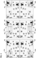
- FIG. 4 shows an illustrative example depicting alignment of a real image of a large automotive part with a synthetic image 402.
- the images herein are schematically represented as line drawings.
- a total of six real images 404a, 404b, 404c, 404d, 404e, 404f are acquired to capture the whole part, while the synthetic image 402 includes a single high-resolution image.
- One way of accomplishing the image acquisition task may include mounting a movable array of sensors over the automotive part (3 sensors in this case) which can be triggered to capture images in two positions.
- images 404a-404c are captured when the sensor array is in a first position while images 404d-404f are captured when the sensor array has moved to a second position over the automotive part.
- the sensor array may be stationary while the part is movable on a conveyor belt relative to the sensor array.
- an array of six stationary sensors may be positioned to the capture different regions of the large part.
- each of the real images 404a-404f is aligned with the synthetic image 402, for example, based on a process of image registration as described above.
- each image 404a-404f is positioned at a respective location over the synthetic image 402 as determined by a respective registration transformation matrix.
- the synthetic image 402 includes bounding boxes 406 locating ROIs based on FLD analysis. As shown, respective bounding boxes 406 are overlaid on each aligned image 404a-404f to extract patches corresponding to high-risk regions. In an alternate approach, the images 404a-404f may be stitched into a single image of the entire part prior to alignment with the synthetic image 402 and overlay of the bounding boxes 406. The above-described process may be repeated for each image in the set of real training images 108.
- the high-risk region extraction engine 110 may be provided with an alert list 112 by an operator, specifying one or more regions in addition to that obtained from the FLD analysis.
- the operator-specified regions of interest may be determined, for example, based on domain specific knowledge.
- the high-risk region extraction engine 110 may be configured to locate (e.g., using bounding boxes) and extract patches from the real training images 108 that correspond to those specified regions in addition to the FLD informed ROIs.
- the system 100 further comprises a model training engine 116 for training a machine learning model 118 for anomaly detection using a training dataset comprising the extracted patches 114 from the set of real training images 108.
- the machine learning model 118 may typically comprise a deep learning model including one or more neural networks. For a neural network, an "anomaly" is usually defined as an out-of-normal-distribution sample.
- the deep learning model 118 may include a skeleton neural network (e.g., with unadjusted weights and biases).
- the model training engine 116 may be configured to train the deep learning model 118 via an unsupervised deep learning process in which the set of training images 108 consist only of nominal images, i.e., real images of defect-free manufactured parts.
- the deep learning model 118 may thereby be trained to learn a distribution of normal data pertaining specifically to the extracted high-risk regions.
- the model training engine 116 may be configured to train the deep learning model 118 via a semi-supervised or supervised learning process.
- the deep learning model 118 may comprise an autoencoder, and desirably, an autoencoder having an extended architecture with custom layers and multi-loss functions.
- An autoencoder is an unsupervised artificial neural network that can learn how to efficiently compress and encode data and then reconstruct the data back from the reduced encoded representation to a representation that is as close to the original input as possible.
- Autoencoders can be used for image anomaly detection, for example, as described in the publication: Paul Bergmann, Michael Fauser, David Sattlegger, Carsten Steger; Proceedings of the IEEE/CVF Conference on Computer Vision and Pattern Recognition (CVPR), 2019, pp. 9592-9600 .
- the trained deep learning model referred to herein as the physics-informed anomaly detection model 120
- the physics-informed anomaly detection model 120 may be deployed to a computing system, such as an industrial computing device for inspecting a manufacturing line for defective parts.
- the physics-informed anomaly detection model 120 may be capable of detecting a variety of different types of defects without being explicitly trained on any specific type of defect, by detecting anomalies in certain high-risk regions of an image of a formed metal part.
- the disclosed methodology requires the deployed physics-informed anomaly detection model 120 to process small portions or patches extracted from the acquired image of the formed metal part, making the model highly efficient and sensitive even to very small defects (e.g., less than 3mm) in expected regions.
- FIG. 5 shows an exemplary embodiment of a system 500 for inspecting a manufacturing line.
- the various engines 508, 510, 512, 514 described herein, including components thereof, may be implemented by a computing system in various ways, for example, as hardware and programming.
- the programming for the engines 508, 510, 512, 514 may take the form of processor-executable instructions stored on non-transitory machine-readable storage mediums and the hardware for the engines may include processors to execute those instructions.
- An example of a computing system suitable for implementing the various engines is described below referring to FIG. 8 .
- such a computing system be provided with one or more deep learning processors such as neural processing units (NPU) to run the deployed deep learning models in a computationally efficient fashion.
- NPU neural processing units
- the system 500 may comprise at least one sensor 502 positioned to acquire images 506 of formed metal parts in a manufacturing line 504.
- the manufacturing line 504 may comprise a queue of formed metal parts positioned on a conveyor system.
- the manufacturing line 504 may be a press line for producing automotive parts by a stamping process.
- one or more sensors may be employed to capture one or more images of an individual part.
- an array of sensors may be used to capture images of different regions of the part.
- the acquired image 506 for each individual part in the manufacturing line 504 may accordingly include a single image or a plurality of images.
- the senor(s) 502 may be used to acquire an image 506 for each individual part in the manufacturing line 504, which may be provided as an input to a physics-informed anomaly detection engine 508.
- the physics-informed anomaly detection engine 508 utilizes the above-described physics-informed anomaly detection model 120, to extract one or more patches from the acquired image 506 that correspond to high-risk regions and detect an anomaly in the one or more patches to identify a defect in the formed metal part.
- the physics-informed anomaly detection engine 508 may first register the acquired image 506 to be aligned with the synthetic image 104 to extract patches from the acquired image 506 corresponding to the high-risk regions, based on the one or more regions of interest in the synthetic image 104.
- the registration process may utilize the pre-aligned reference real image that was used to register the set of training images 108.
- feature points may be automatically detected in the incoming image 506 (e.g., using ORB method) and matched with corresponding feature points on the reference real image. Thereby, by registering each acquired image 506 with the reference real image, the respective acquired image 506 is also aligned or registered with the synthetic image 104.
- the bounding boxes on the synthetic image 104 may be overlaid on the acquired image 506 to extract the patches corresponding to the high-risk regions. Again, the bounding boxes may be overlaid on a single acquired image of the entire part or on multiple acquired images corresponding to different regions of the part (for example, as described in FIG. 4 ), to extract the patches.
- the physics-informed anomaly detection engine 508 may reconstruct a respective nominal image for each extracted patch of the acquired image 506.
- FIG. 6 shows an example of an extracted patch 602 that represents a small but high-risk region in an acquired image of a formed metal part.
- the images herein are schematically represented as line drawings.
- the extracted patch 602 includes defects 604a, 604b, 604c, 604d. Since the deep learning model was trained to only learn distribution of normal data (without defects) pertaining to the extracted regions, any defects such as 604a, 604b, 604c, 604d appearing on the extracted patch 602 will not recognized by the model. The reconstructed nominal image would thereby exclude such defects as being out-of-normal-distribution. Defects in the acquired image 506 may be revealed by comparing each extracted patch of the acquired image (e.g., patch 602) to the respective reconstructed nominal image, to detect an anomaly.
- each extracted patch of the acquired image e.g., patch 602
- the physics-informed anomaly detection engine 508 may determine a pixel-wise location of a defect based on a loss map, which is defined by a difference between the extracted patch of the acquired image and the reconstructed nominal image.
- FIG. 6 shows an example of a loss map 606 corresponding to the extracted patch 602.
- the loss map 606 may be generated by determining a pixel-wise anomaly score based on a reconstruction error between the extracted image patch 602 and the reconstructed nominal image corresponding to the patch 602, with higher scores representing more likely anomalies.
- the residual map may be smoothed out by filtering.
- a binary segmentation may be carried out to identify the location of an anomaly.
- the anomalies 608a, 608b, 608c, 608d in the loss map 606 indicate the location of the defects 604a, 604b, 604c, 604d respectively.
- a post processing engine 514 may be used to draw bounding boxes around the determined locations of the defects on the actual acquired image 506 of the formed metal part (e.g., based on the loss maps).
- the identified defects relevant information including the presence and location of the identified defects, can then be visualized and displayed to the operator via a user interface 516, such as an HMI device, among others.
- the system 500 may comprise a generic anomaly detection engine 510 in addition to a physics-informed anomaly detection engine 508, as shown in FIG. 5 .
- the physics-informed anomaly detection engine 508 can detect defects efficiently and with high sensitivity in regions of a formed metal part that have a high risk of developing defects, in rare instances, defects can randomly develop in other regions of the formed part.
- the generic anomaly detection engine 510 may utilize a separate deep learning model trained on entire images in the set of training images to detect randomly occurring defects on any portion of a formed metal part.
- the deep learning model for generic anomaly detection may also be trained via an unsupervised deep learning process using only nominal real images of manufactured parts as training images, to learn a distribution of normal data pertaining to the entire image.
- the generic anomaly detection engine 510 can detect defects on the whole part, it may not be nearly as sensitive as the physics-informed anomaly detection engine 508 in detecting defects in the high-risk regions.
- the combination of the physics-informed anomaly detection engine 508 and the generic anomaly detection engine 510 may thereby significantly improve the reliability and sensitivity of the system 500.
- the physics-informed anomaly detection engine 508 may be employed either individually or in combination with the generic anomaly detection engine 510.
- the acquired image 506 of each individual part may be simultaneously provided as input to both, the generic anomaly detection engine 510 and the physics-informed anomaly detection engine 508.
- the generic anomaly detection engine 510 may reconstruct a nominal image corresponding to the entire acquired image 506 and compare the entire acquired image 506 to the reconstructed nominal image to detect an anomaly and locate a defect anywhere in the acquired image, for example, by generating a loss map as described above.
- the system 500 may further comprise a model output combination engine 512 for combining outputs of the physics-informed anomaly detection engine 508 and the generic anomaly detection engine 510, to generate a common output indicating presence and location of one or more defects on the acquired image 506.
- the outputs of the two anomaly detection engines 508 and 510 may be combined in many ways. According to one embodiment, the loss maps output by the two anomaly detection engines 508 and 510 may be combined in a way such that, for overlapping regions of the acquired image that are processed by both the anomaly detection engines 508 and 510, a positive detection by the physics-informed anomaly detection engine 508 is prioritized.
- the combined output would indicate presence of a defect at a location where only the physics-informed anomaly detection engine 508 reacted with a positive anomaly detection but the generic anomaly detection engine 510 did not react.
- the detected defects may also be assigned a confidence score based on the combined output of the anomaly detection engines 508 and 510 (e.g., a high score if both models react).
- the output of the generic anomaly detection engine 510 may be solely used to indicate the presence and location of a defect.
- the post-processing engine 514 may be used to draw bounding boxes around the locations of the defects on the actual acquired image 506 of the formed metal part, as determined by the model output combination engine 512.
- the identified defects relevant information including the presence and location of the identified defects, can then be visualized and displayed to the operator via a user interface 516, such as an HMI device, among others.
- FIG. 7 shows a visualization 700 of a combined output of the physics-informed anomaly detection engine 508 and the generic anomaly detection engine 510.
- the images herein are schematically represented as line drawings.
- synthetically generated defects, as determined by the model output combination engine 512 are located by bounding boxes 702.
- control action may include isolating a defective part from production, shutting down production to avoid a catastrophic event (e.g., defects are detected in a succession of formed parts), and so on.
- the control action may be executed automatically, semi-automatically, or manually, responsive to the output of the anomaly detection engine(s), specifically, a positive defect detection in one or more formed metal parts in the manufacturing line 504. For example, in one embodiment, as shown in FIG.
- the system 500 may include a field controller 518 for automatically executing a control action to control the manufacturing line 504 based on the output of the anomaly detection engine(s).
- the field controller 518 may comprise or be integrated with automation system equipment such as PLCs (Programmable Logic Controllers), drives, etc. for executing the control action.
- operators can correct or override the automatically determined defects detected by, e.g., drawing a bounding box to missing defects, or pass the false alarm samples. All those missing defects and false alarms data may be stored in record for updating the deep learning models.
- FIG. 8 shows an example of a computing system 800 that can support detection of a defect in a formed metal part in a manufacturing line according to disclosed embodiments.
- the computing system 800 may be configured as an edge-enabled device.
- the computing system 800 includes at least one processor 810, which may take the form of a single or multiple processors.
- the processor(s) 810 may include a central processing unit (CPU), a graphics processing unit (GPU), a neural processing unit (NPU), a microprocessor, or any hardware device suitable for executing instructions stored on a memory comprising a machine-readable medium.
- the computing system 800 further includes a machine-readable medium 820.
- the machine-readable medium 820 may take the form of any non-transitory electronic, magnetic, optical, or other physical storage device that stores executable instructions, such as physics-informed anomaly detection instructions 822, generic anomaly detection instructions 824, model output combination instructions 826 and post processing instructions 828, as shown in FIG. 8 .
- the machine-readable medium 820 may be, for example, Random Access Memory (RAM) such as a dynamic RAM (DRAM), flash memory, spin-transfer torque memory, an Electrically-Erasable Programmable Read-Only Memory (EEPROM), a storage drive, an optical disk, and the like.
- RAM Random Access Memory
- DRAM dynamic RAM
- EEPROM Electrically-Erasable Programmable Read-Only Memory
- the computing system 800 may execute instructions stored on the machine-readable medium 820 through the processor(s) 810. Executing the instructions (e.g., the physics-informed anomaly detection instructions 822, the generic anomaly detection instructions 824, the model output combination instructions 826 and the post processing instructions 828) may cause the computing system 800 to perform any of the technical features described herein, including according to any of the features of the physics-informed anomaly detection engine 508, the generic anomaly detection engine 510, the model output combination engine 512 and the post processing engine 514 described above.
- Executing the instructions e.g., the physics-informed anomaly detection instructions 822, the generic anomaly detection instructions 824, the model output combination instructions 826 and the post processing instructions 828, may cause the computing system 800 to perform any of the technical features described herein, including according to any of the features of the physics-informed anomaly detection engine 508, the generic anomaly detection engine 510, the model output combination engine 512 and the post processing engine 514 described above.
- the systems, methods, devices, and logic described above may be implemented in many different ways in many different combinations of hardware, logic, circuitry, and executable instructions stored on a machine-readable medium.
- these engines may include circuitry in a controller, a microprocessor, or an application specific integrated circuit (ASIC), or may be implemented with discrete logic or components, or a combination of other types of analog or digital circuitry, combined on a single integrated circuit or distributed among multiple integrated circuits.
- ASIC application specific integrated circuit
- a product such as a computer program product, may include a storage medium and machine-readable instructions stored on the medium, which when executed in an endpoint, computer system, or other device, cause the device to perform operations according to any of the description above, including according to any features of the physics-informed anomaly detection engine 508, the generic anomaly detection engine 510, the model output combination engine 512 and the post processing engine 514.
- Computer readable program instructions described herein can be downloaded to respective computing/processing devices from a computer readable storage medium or to an external computer or external storage device via a network, for example, the Internet, a local area network, a wide area network and/or a wireless network.
- the processing capability of the systems, devices, and engines described herein, including the physics-informed anomaly detection engine 508, the generic anomaly detection engine 510, the model output combination engine 512 and the post processing engine 514 may be distributed among multiple system components, such as among multiple processors and memories, optionally including multiple distributed processing systems or cloud/network elements.
- Parameters, databases, and other data structures may be separately stored and managed, may be incorporated into a single memory or database, may be logically and physically organized in many different ways, and may be implemented in many ways, including data structures such as linked lists, hash tables, or implicit storage mechanisms.
- Programs may be parts (e.g., subroutines) of a single program, separate programs, distributed across several memories and processors, or implemented in many different ways, such as in a library (e.g., a shared library).
Landscapes
- Engineering & Computer Science (AREA)
- Theoretical Computer Science (AREA)
- Physics & Mathematics (AREA)
- General Physics & Mathematics (AREA)
- Computer Vision & Pattern Recognition (AREA)
- Multimedia (AREA)
- Quality & Reliability (AREA)
- Artificial Intelligence (AREA)
- Health & Medical Sciences (AREA)
- Computing Systems (AREA)
- Databases & Information Systems (AREA)
- Evolutionary Computation (AREA)
- General Health & Medical Sciences (AREA)
- Medical Informatics (AREA)
- Software Systems (AREA)
- Image Analysis (AREA)
Claims (15)
- Computergestütztes Verfahren zum Erkennen von Schäden in einem geformten Metallteil, umfassend:Auffinden eines oder mehrerer interessierender Gebiete in einem synthetischen Bild eines Bauteils, das durch einen Formprozess gefertigt wird, wobei das synthetische Bild auf der Grundlage einer physikalisch basierten Simulation eines Materialzustands unterrichtet wird, der sich aus dem Formprozess ergibt, wobei das eine oder die mehreren interessierenden Gebiete anzeigen, dass sie ein höheres Risiko für einen Schaden aufweisen, der sich aus dem Formprozess ergibt, als andere Gebiete in dem synthetischen Bild,Registrieren einer Gruppe von Trainingsbildern, die echte Bilder von tatsächlichen Bauteilen umfassen, die gemäß dem Formprozess gefertigt wurden, zusammen mit dem synthetischen Bild und Überlagern des einen oder mehreren interessierenden Gebiete in jedem der Trainingsbilder, um Ausschnitte aus den Trainingsbildern zu extrahieren, die Hochrisikogebieten entsprechen, undTrainieren eines ersten Anomalieerkennungsmodells (120) an den Ausschnitten, die aus den Trainingsbildern extrahiert wurden, wobei das erste Anomalieerkennungsmodell durch einen Prozessor ausführbar ist, um einen Schaden in einem geformten Metallteil, das in einer Fertigungslinie gemäß dem Formprozess gefertigt wurde, aus einem erfassten Bild des geformten Metallteils zu erkennen, indem eine Anomalie in einem Ausschnitt erkannt wird, der aus dem erfassten Bild extrahiert wurde und der einem Hochrisikogebiet entspricht.
- Verfahren nach Anspruch 1, wobei das Auffinden eines oder mehrerer interessierender Gebiete ein Zuordnen einer Farbe und/oder einer Intensität von verschiedenen Gebieten des Bauteils in dem synthetischen Bild zu einem simulierten Belastungsgrad umfasst, der sich aus dem Formprozess ergibt, wobei das Zuordnen der Farbe und/oder der Intensität auf einem Grenzformänderungsdiagramm beruht, das zu einem Material des Bauteils gehört; und
Auffinden des eines oder der mehreren interessierenden Gebiete gemäß dem Belastungsgrad. - Verfahren nach einem der Ansprüche 1 und 2, wobei das Auffinden des einen oder der mehreren interessierenden Gebiete in dem synthetischen Bild ein Ermitteln eines Begrenzungsrechtecks für jedes interessierende Gebiet umfasst, wobei die Begrenzungsrechtecke auf die Trainingsbilder überlagert werden, um die Ausschnitte aus den Trainingsbildern zu extrahieren, die den Hochrisikogebieten entsprechen.
- Verfahren nach einem der Ansprüche 1 bis 3, wobei das Trainieren des ersten Anomalieerkennungsmodells einen unüberwachten Tiefenlernprozess umfasst, in dem die Gruppe von Trainingsbildern nur nominale echte Bilder von gefertigten Bauteilen umfasst, um das erste Anomalieerkennungsmodell zum Erlernen einer Verteilung von normalen Daten zu trainieren, die zu den Hochrisikogebieten gehören.
- Verfahren nach einem der Ansprüche 1 bis 4, das ein Ausführen, durch einen oder mehrere Prozessoren, der Anweisungen zum Überprüfen einer Fertigungslinie umfasst, wobei das Ausführen der Anweisungen umfasst:Erfassen eines Bildes eines geformten Metallteils in der Fertigungslinie über einen oder mehrere Sensoren (502),Registrieren, durch eine physikalisch unterrichtete Engine zum Erkennen von Anomalien (508), die das erste Anomalieerkennungsmodell (120) umfasst, des erfassten Bildes mit dem synthetischen Bild; und Extrahieren von Ausschnitten aus dem erfassten Bild, die den Hochrisikogebieten entsprechen, auf der Grundlage von einem oder mehreren interessierenden Gebieten in dem synthetischen Bild,Wiederherstellen, durch das erste Anomalieerkennungsmodell (120) eines nominalen Bildes, das jedem extrahierten Ausschnitt des erfassten Bildes entspricht, undVergleichen, durch die physikalisch unterrichtete Engine zum Erkennen von Anomalien (508), von jedem extrahierten Ausschnitt des erfassten Bildes mit dem entsprechenden wiederhergestellten nominalen Bild, um eine Anomalie zu erkennen.
- Verfahren nach Anspruch 5, das ein pixelweises Ermitteln eines Orts eines Schadens auf der Grundlage einer Verlustzuordnung zwischen jedem extrahierten Ausschnitt des erfassten Bildes und dem entsprechenden wiederhergestellten nominalen Bild umfasst.
- Verfahren nach Anspruch 6, das eine Visualisierung des Schadens über eine Benutzeroberfläche umfasst, indem ein Begrenzungsrechteck um den ermittelten Ort des Schadens in dem erfassten Bild des geformten Metallteils gezeichnet wird.
- Verfahren nach einem der Ansprüche 5 bis 7, das ferner ein Ausführen eines zweiten Anomalieerkennungsmodells durch den einen oder die mehreren Prozessoren zum Überprüfen der Fertigungslinie umfasst, wobei das zweite Anomalieerkennungsmodell an vollständigen Bildern in der Gruppe von Trainingsbildern trainiert wird, um zufällig auftretende Schäden an einem beliebigen Abschnitt eines geformten Metallteils zu erkennen, wobei das Ausführen des zweiten Anomalieerkennungsmodells umfasst:Wiederherstellen eines nominalen Bildes, das dem vollständigen erfassten Bild entspricht undVergleichen des vollständigen erfassten Bildes mit dem wiederhergestellten nominalen Bild, um eine Anomalie zu erkennen und einen Schaden aufzufinden.
- Verfahrens nach Anspruch 8, das ein Kombinieren von Ausgaben des ersten und des zweiten Anomalieerkennungsmodells, um eine gemeinsame Ausgabe zu erzeugen, die das Vorhandensein und den Ort von einem oder mehreren Schäden in dem erfassten Bild anzeigt, und ein Visualisieren der gemeinsamen Ausgabe über eine Benutzeroberfläche umfasst.
- Verfahren nach Anspruch 9, wobei das Kombinieren der Ausgaben ein Priorisieren einer positiven Erkennung durch das erste Anomalieerkennungsmodell in Gebieten des erfassten Bildes umfasst, die sowohl durch das erste als auch das zweite Anomalieerkennungsmodell verarbeitet werden.
- Verfahren nach einem der Ansprüche 8 bis 10, das ferner ein Ausführen einer Steueraktion umfasst, um die Fertigungslinie als Reaktion auf eine Ausgabe des ersten Anomalieerkennungsmodells oder auf der Grundlage einer kombinierten Ausgabe des ersten und des zweiten Anomalieerkennungsmodells zu steuern.
- Nicht-flüchtiges computerlesbares Speichermedium, das Anweisungen beinhaltete, die, wenn sie durch ein Computersystem verarbeitet werden, das Computersystem zum Durchführen des Verfahrens nach einem der Ansprüche 1 bis 11 konfigurieren.
- System zum Überprüfen einer Fertigungslinie, umfassend:einen oder mehrere Sensoren zum diskreten Aufnehmen von Bildern von geformten Metallteilen in der Fertigungslinie, undein Computersystem, umfassend:einen oder mehrere Prozessoren,einen Speicher, in dem algorithmische Module gespeichert sind, die durch den einen oder die mehreren Prozessoren ausführbar sind, wobei die algorithmischen Module umfassen:
eine Engine zum Trainieren von Modellen (116), eine physikalisch unterrichtete Engine zum Erkennen von Anomalien (508), die ein erstes Anomalieerkennungsmodell (120) verwendet, wobei das erste Anomalieerkennungsmodell durch die Engine zum Trainieren von Modellen (116) mit einem Verfahren nach einem der Ansprüche 1 bis 4 trainiert wird, wobei die physikalisch unterrichtete Engine zum Erkennen von Anomalien konfiguriert ist zum:Erfassen eines Bildes eines geformten Metallteils in der Fertigungslinie über einen oder mehrere Sensoren,Extrahieren eines Ausschnitts aus dem erfassten Bild, der einem Hochrisikogebiet entspricht, undErkennen, unter Verwendung des ersten Anomalieerkennungsmodells, einer Anomalie in dem extrahierten Ausschnitt, um einen Schaden in dem geformten Metallteil zu erkennen. - System nach Anspruch 13, wobei die algorithmischen Module ferner eine generische Engine zum Erkennen von Anomalien umfassen, die ein zweites Anomalieerkennungsmodell verwendet, das an vollständigen Bildern in der Gruppe von Trainingsbildern trainiert wird, um zufällig auftretende Schäden an einem beliebigen Abschnitt eines geformten Metallteils zu erkennen,
wobei die generische Engine zum Erkennen von Anomalien konfiguriert ist zum Vergleichen der Gesamtheit des erfassten Bildes mit der Gesamtheit des wiederhergestellten nominalen Bildes, um einen Schaden in dem geformten Metallteil zu identifizieren. - System nach Anspruch 14, wobei die algorithmischen Module ferner eine Engine für eine Modellausgabekombination umfassen, um ein Vorhandensein und einen Ort von einem oder mehreren Schäden in dem erfassten Bild des geformten Metallteils auf der Grundlage einer Kombination der physikalisch unterrichtete Engine zum Erkennen von Anomalien und der generischen Engine zum Erkennen von Anomalien zu ermitteln.
Priority Applications (4)
| Application Number | Priority Date | Filing Date | Title |
|---|---|---|---|
| EP22151483.9A EP4213091B1 (de) | 2022-01-14 | 2022-01-14 | Erkennung von anomalien in geformten metallteilen auf der grundlage physikalischer daten |
| ES22151483T ES2989011T3 (es) | 2022-01-14 | 2022-01-14 | Detección de anomalías basada en la física en piezas metálicas conformadas |
| US18/149,686 US12394037B2 (en) | 2022-01-14 | 2023-01-04 | Physics-informed anomaly detection in formed metal parts |
| CN202310066366.8A CN116452493A (zh) | 2022-01-14 | 2023-01-12 | 用于检测成型金属部件中的缺陷的方法 |
Applications Claiming Priority (1)
| Application Number | Priority Date | Filing Date | Title |
|---|---|---|---|
| EP22151483.9A EP4213091B1 (de) | 2022-01-14 | 2022-01-14 | Erkennung von anomalien in geformten metallteilen auf der grundlage physikalischer daten |
Publications (3)
| Publication Number | Publication Date |
|---|---|
| EP4213091A1 EP4213091A1 (de) | 2023-07-19 |
| EP4213091C0 EP4213091C0 (de) | 2024-08-14 |
| EP4213091B1 true EP4213091B1 (de) | 2024-08-14 |
Family
ID=80112476
Family Applications (1)
| Application Number | Title | Priority Date | Filing Date |
|---|---|---|---|
| EP22151483.9A Active EP4213091B1 (de) | 2022-01-14 | 2022-01-14 | Erkennung von anomalien in geformten metallteilen auf der grundlage physikalischer daten |
Country Status (4)
| Country | Link |
|---|---|
| US (1) | US12394037B2 (de) |
| EP (1) | EP4213091B1 (de) |
| CN (1) | CN116452493A (de) |
| ES (1) | ES2989011T3 (de) |
Families Citing this family (8)
| Publication number | Priority date | Publication date | Assignee | Title |
|---|---|---|---|---|
| KR20240067420A (ko) * | 2022-11-09 | 2024-05-17 | 현대자동차주식회사 | 사이드 아우터 추출 시스템 및 사이드 아우터 추출 방법 |
| CN117274190A (zh) * | 2023-09-20 | 2023-12-22 | 深圳智机视觉科技有限公司 | 手机摄像头支架的缺陷检测方法、计算机设备及存储介质 |
| CN117876364A (zh) * | 2024-03-11 | 2024-04-12 | 陕西煜成和汇金属材料有限公司 | 基于图像识别的金属棒材缺陷检测方法及系统 |
| CN119295367B (zh) * | 2024-08-19 | 2025-06-27 | 北京奔驰汽车有限公司 | 一种生产线冲压件质量检测方法、装置及系统 |
| CN122003698A (zh) * | 2024-09-02 | 2026-05-08 | 京东方科技集团股份有限公司 | 缺陷检测方法、电子设备、存储介质及程序产品 |
| CN119048519B (zh) * | 2024-11-01 | 2025-03-18 | 四川托璞勒科技股份有限公司 | 刀具状态检测方法、装置、电子设备及可读存储介质 |
| CN119673346B (zh) * | 2024-12-17 | 2025-10-17 | 华中科技大学 | 一种金属材料多模态融合的仿真数据生成方法 |
| CN120235760B (zh) * | 2025-05-21 | 2025-08-12 | 浙江巨丰模架有限公司 | 一种快速定位的模架精度的检测控制方法及系统 |
Family Cites Families (8)
| Publication number | Priority date | Publication date | Assignee | Title |
|---|---|---|---|---|
| US20080004850A1 (en) * | 2006-06-05 | 2008-01-03 | Phida, Inc. | Method of Universal Formability Analysis in Sheet Metal Forming by Utilizing Finite Element Analysis and Circle Grid Analysis |
| US10861147B2 (en) * | 2015-01-13 | 2020-12-08 | Sikorsky Aircraft Corporation | Structural health monitoring employing physics models |
| US10907957B2 (en) * | 2017-05-16 | 2021-02-02 | Oakland University | Method of measuring localized strains in sheet metal stampings |
| US11199506B2 (en) * | 2018-02-21 | 2021-12-14 | Applied Materials Israel Ltd. | Generating a training set usable for examination of a semiconductor specimen |
| US10896341B2 (en) * | 2018-11-15 | 2021-01-19 | International Business Machines Corporation | Efficient defect localization/segmentation for surface defect inspection |
| SE1930421A1 (en) * | 2019-12-30 | 2021-07-01 | Unibap Ab | Method and means for detection of imperfections in products |
| CN111223093A (zh) * | 2020-03-04 | 2020-06-02 | 武汉精立电子技术有限公司 | 一种aoi缺陷检测方法 |
| CN113610794A (zh) * | 2021-07-30 | 2021-11-05 | 无锡瑞视晶科技有限公司 | 一种基于生成式对抗网络的金属表面瑕疵检测方法 |
-
2022
- 2022-01-14 EP EP22151483.9A patent/EP4213091B1/de active Active
- 2022-01-14 ES ES22151483T patent/ES2989011T3/es active Active
-
2023
- 2023-01-04 US US18/149,686 patent/US12394037B2/en active Active
- 2023-01-12 CN CN202310066366.8A patent/CN116452493A/zh active Pending
Also Published As
| Publication number | Publication date |
|---|---|
| US20230230224A1 (en) | 2023-07-20 |
| ES2989011T3 (es) | 2024-11-25 |
| EP4213091A1 (de) | 2023-07-19 |
| EP4213091C0 (de) | 2024-08-14 |
| US12394037B2 (en) | 2025-08-19 |
| CN116452493A (zh) | 2023-07-18 |
Similar Documents
| Publication | Publication Date | Title |
|---|---|---|
| US12394037B2 (en) | Physics-informed anomaly detection in formed metal parts | |
| US12183066B2 (en) | Method of deep learning-based examination of a semiconductor specimen and system thereof | |
| CN111325713B (zh) | 基于神经网络的木材缺陷检测方法、系统及存储介质 | |
| CN111507976B (zh) | 基于多角度成像的缺陷检测方法及系统 | |
| EP3791336B1 (de) | System und verfahren zur erkennung von fehlern auf abgebildeten objekten | |
| Martins et al. | Automatic detection of surface defects on rolled steel using computer vision and artificial neural networks | |
| EP4515486B1 (de) | Selbstüberwachter anomaliedetektionsrahmen zur visuellen qualitätsinspektion bei der herstellung | |
| Kim et al. | A vision-based system for monitoring block assembly in shipbuilding | |
| KR102297232B1 (ko) | 형태학적 영상처리를 활용한 이상 탐지 방법 | |
| TW201606854A (zh) | 用於晶粒對資料庫光罩檢查之自動校準樣本選擇 | |
| CN113902695B (zh) | 一种针对色织物裁片缺陷区域的检测方法 | |
| CN117274148B (zh) | 基于深度学习的无监督晶圆缺陷检测方法 | |
| CN115564734B (zh) | 一种产品检测方法、电子设备及存储介质 | |
| CN114565825B (zh) | 一种基于图像识别的安检复检方法及系统 | |
| CN119205646A (zh) | 基于工件生产的人工智能视觉检测方法、系统及装置 | |
| Serrano et al. | Development of an Artificial Vision Algorithm for T-shirt Inspection | |
| Weimer et al. | Context-aware deep convolutional neural networks for industrial inspection | |
| JP7345764B2 (ja) | 検査システムおよび検査プログラム | |
| Vengaloor et al. | Automatic Surface Defect Detection System for White-Goods Logistics Industries using mU-NET | |
| TWI918531B (zh) | 異常導引式皮革瑕疵自動分類定位方法及其系統 | |
| Subramanian et al. | Revolutionizing Manufacturing Quality Control with Optimized ResNet50: A Deep Learning Approach for Real-Time Defect Detection | |
| CN117809138B (zh) | 一种多余物检测图像数据集增强方法及系统 | |
| Monti et al. | Die-vis: an automated visual inspection system for cardboard box manufacturing | |
| Dong et al. | Artificial Intelligence Defect Detection Robustness in Real-time Non-Destructive Testing of Metal Surfaces | |
| Priya et al. | A Novel Computer Vision Framework for the Automated Visual Inspection for Quality Control of Automotive Fasteners |
Legal Events
| Date | Code | Title | Description |
|---|---|---|---|
| PUAI | Public reference made under article 153(3) epc to a published international application that has entered the european phase |
Free format text: ORIGINAL CODE: 0009012 |
|
| STAA | Information on the status of an ep patent application or granted ep patent |
Free format text: STATUS: REQUEST FOR EXAMINATION WAS MADE |
|
| 17P | Request for examination filed |
Effective date: 20220114 |
|
| AK | Designated contracting states |
Kind code of ref document: A1 Designated state(s): AL AT BE BG CH CY CZ DE DK EE ES FI FR GB GR HR HU IE IS IT LI LT LU LV MC MK MT NL NO PL PT RO RS SE SI SK SM TR |
|
| RBV | Designated contracting states (corrected) |
Designated state(s): AL AT BE BG CH CY CZ DE DK EE ES FI FR GB GR HR HU IE IS IT LI LT LU LV MC MK MT NL NO PL PT RO RS SE SI SK SM TR |
|
| GRAP | Despatch of communication of intention to grant a patent |
Free format text: ORIGINAL CODE: EPIDOSNIGR1 |
|
| STAA | Information on the status of an ep patent application or granted ep patent |
Free format text: STATUS: GRANT OF PATENT IS INTENDED |
|
| INTG | Intention to grant announced |
Effective date: 20240315 |
|
| GRAS | Grant fee paid |
Free format text: ORIGINAL CODE: EPIDOSNIGR3 |
|
| GRAA | (expected) grant |
Free format text: ORIGINAL CODE: 0009210 |
|
| STAA | Information on the status of an ep patent application or granted ep patent |
Free format text: STATUS: THE PATENT HAS BEEN GRANTED |
|
| AK | Designated contracting states |
Kind code of ref document: B1 Designated state(s): AL AT BE BG CH CY CZ DE DK EE ES FI FR GB GR HR HU IE IS IT LI LT LU LV MC MK MT NL NO PL PT RO RS SE SI SK SM TR |
|
| REG | Reference to a national code |
Ref country code: GB Ref legal event code: FG4D |
|
| REG | Reference to a national code |
Ref country code: CH Ref legal event code: EP |
|
| REG | Reference to a national code |
Ref country code: DE Ref legal event code: R096 Ref document number: 602022005223 Country of ref document: DE |
|
| REG | Reference to a national code |
Ref country code: IE Ref legal event code: FG4D |
|
| U01 | Request for unitary effect filed |
Effective date: 20240814 |
|
| U07 | Unitary effect registered |
Designated state(s): AT BE BG DE DK EE FI FR IT LT LU LV MT NL PT RO SE SI Effective date: 20240902 |
|
| REG | Reference to a national code |
Ref country code: ES Ref legal event code: FG2A Ref document number: 2989011 Country of ref document: ES Kind code of ref document: T3 Effective date: 20241125 |
|
| PG25 | Lapsed in a contracting state [announced via postgrant information from national office to epo] |
Ref country code: NO Free format text: LAPSE BECAUSE OF FAILURE TO SUBMIT A TRANSLATION OF THE DESCRIPTION OR TO PAY THE FEE WITHIN THE PRESCRIBED TIME-LIMIT Effective date: 20241114 |
|
| PG25 | Lapsed in a contracting state [announced via postgrant information from national office to epo] |
Ref country code: PL Free format text: LAPSE BECAUSE OF FAILURE TO SUBMIT A TRANSLATION OF THE DESCRIPTION OR TO PAY THE FEE WITHIN THE PRESCRIBED TIME-LIMIT Effective date: 20240814 Ref country code: GR Free format text: LAPSE BECAUSE OF FAILURE TO SUBMIT A TRANSLATION OF THE DESCRIPTION OR TO PAY THE FEE WITHIN THE PRESCRIBED TIME-LIMIT Effective date: 20241115 |
|
| PG25 | Lapsed in a contracting state [announced via postgrant information from national office to epo] |
Ref country code: IS Free format text: LAPSE BECAUSE OF FAILURE TO SUBMIT A TRANSLATION OF THE DESCRIPTION OR TO PAY THE FEE WITHIN THE PRESCRIBED TIME-LIMIT Effective date: 20241214 |
|
| PG25 | Lapsed in a contracting state [announced via postgrant information from national office to epo] |
Ref country code: HR Free format text: LAPSE BECAUSE OF FAILURE TO SUBMIT A TRANSLATION OF THE DESCRIPTION OR TO PAY THE FEE WITHIN THE PRESCRIBED TIME-LIMIT Effective date: 20240814 |
|
| PG25 | Lapsed in a contracting state [announced via postgrant information from national office to epo] |
Ref country code: RS Free format text: LAPSE BECAUSE OF FAILURE TO SUBMIT A TRANSLATION OF THE DESCRIPTION OR TO PAY THE FEE WITHIN THE PRESCRIBED TIME-LIMIT Effective date: 20241114 |
|
| PG25 | Lapsed in a contracting state [announced via postgrant information from national office to epo] |
Ref country code: RS Free format text: LAPSE BECAUSE OF FAILURE TO SUBMIT A TRANSLATION OF THE DESCRIPTION OR TO PAY THE FEE WITHIN THE PRESCRIBED TIME-LIMIT Effective date: 20241114 Ref country code: PL Free format text: LAPSE BECAUSE OF FAILURE TO SUBMIT A TRANSLATION OF THE DESCRIPTION OR TO PAY THE FEE WITHIN THE PRESCRIBED TIME-LIMIT Effective date: 20240814 Ref country code: NO Free format text: LAPSE BECAUSE OF FAILURE TO SUBMIT A TRANSLATION OF THE DESCRIPTION OR TO PAY THE FEE WITHIN THE PRESCRIBED TIME-LIMIT Effective date: 20241114 Ref country code: IS Free format text: LAPSE BECAUSE OF FAILURE TO SUBMIT A TRANSLATION OF THE DESCRIPTION OR TO PAY THE FEE WITHIN THE PRESCRIBED TIME-LIMIT Effective date: 20241214 Ref country code: HR Free format text: LAPSE BECAUSE OF FAILURE TO SUBMIT A TRANSLATION OF THE DESCRIPTION OR TO PAY THE FEE WITHIN THE PRESCRIBED TIME-LIMIT Effective date: 20240814 Ref country code: GR Free format text: LAPSE BECAUSE OF FAILURE TO SUBMIT A TRANSLATION OF THE DESCRIPTION OR TO PAY THE FEE WITHIN THE PRESCRIBED TIME-LIMIT Effective date: 20241115 |
|
| U20 | Renewal fee for the european patent with unitary effect paid |
Year of fee payment: 4 Effective date: 20250120 |
|
| PG25 | Lapsed in a contracting state [announced via postgrant information from national office to epo] |
Ref country code: SM Free format text: LAPSE BECAUSE OF FAILURE TO SUBMIT A TRANSLATION OF THE DESCRIPTION OR TO PAY THE FEE WITHIN THE PRESCRIBED TIME-LIMIT Effective date: 20240814 |
|
| PG25 | Lapsed in a contracting state [announced via postgrant information from national office to epo] |
Ref country code: CZ Free format text: LAPSE BECAUSE OF FAILURE TO SUBMIT A TRANSLATION OF THE DESCRIPTION OR TO PAY THE FEE WITHIN THE PRESCRIBED TIME-LIMIT Effective date: 20240814 |
|
| PG25 | Lapsed in a contracting state [announced via postgrant information from national office to epo] |
Ref country code: SK Free format text: LAPSE BECAUSE OF FAILURE TO SUBMIT A TRANSLATION OF THE DESCRIPTION OR TO PAY THE FEE WITHIN THE PRESCRIBED TIME-LIMIT Effective date: 20240814 |
|
| PLBE | No opposition filed within time limit |
Free format text: ORIGINAL CODE: 0009261 |
|
| STAA | Information on the status of an ep patent application or granted ep patent |
Free format text: STATUS: NO OPPOSITION FILED WITHIN TIME LIMIT |
|
| PGFP | Annual fee paid to national office [announced via postgrant information from national office to epo] |
Ref country code: ES Payment date: 20250422 Year of fee payment: 4 |
|
| 26N | No opposition filed |
Effective date: 20250515 |
|
| REG | Reference to a national code |
Ref country code: CH Ref legal event code: PL |
|
| PG25 | Lapsed in a contracting state [announced via postgrant information from national office to epo] |
Ref country code: MC Free format text: LAPSE BECAUSE OF FAILURE TO SUBMIT A TRANSLATION OF THE DESCRIPTION OR TO PAY THE FEE WITHIN THE PRESCRIBED TIME-LIMIT Effective date: 20240814 |
|
| PG25 | Lapsed in a contracting state [announced via postgrant information from national office to epo] |
Ref country code: CH Free format text: LAPSE BECAUSE OF NON-PAYMENT OF DUE FEES Effective date: 20250131 |
|
| PG25 | Lapsed in a contracting state [announced via postgrant information from national office to epo] |
Ref country code: IE Free format text: LAPSE BECAUSE OF NON-PAYMENT OF DUE FEES Effective date: 20250114 |
|
| U20 | Renewal fee for the european patent with unitary effect paid |
Year of fee payment: 5 Effective date: 20260119 |