EP4213053A1 - Ressourcenzuweisungsverfahren und -vorrichtung sowie speichermedium - Google Patents
Ressourcenzuweisungsverfahren und -vorrichtung sowie speichermedium Download PDFInfo
- Publication number
- EP4213053A1 EP4213053A1 EP20955842.8A EP20955842A EP4213053A1 EP 4213053 A1 EP4213053 A1 EP 4213053A1 EP 20955842 A EP20955842 A EP 20955842A EP 4213053 A1 EP4213053 A1 EP 4213053A1
- Authority
- EP
- European Patent Office
- Prior art keywords
- counter
- sub
- storage resource
- value
- resource
- Prior art date
- Legal status (The legal status is an assumption and is not a legal conclusion. Google has not performed a legal analysis and makes no representation as to the accuracy of the status listed.)
- Pending
Links
Images


Classifications
-
- H—ELECTRICITY
- H04—ELECTRIC COMMUNICATION TECHNIQUE
- H04L—TRANSMISSION OF DIGITAL INFORMATION, e.g. TELEGRAPHIC COMMUNICATION
- H04L9/00—Cryptographic mechanisms or cryptographic arrangements for secret or secure communications; Network security protocols
- H04L9/32—Cryptographic mechanisms or cryptographic arrangements for secret or secure communications; Network security protocols including means for verifying the identity or authority of a user of the system or for message authentication, e.g. authorization, entity authentication, data integrity or data verification, non-repudiation, key authentication or verification of credentials
- H04L9/3236—Cryptographic mechanisms or cryptographic arrangements for secret or secure communications; Network security protocols including means for verifying the identity or authority of a user of the system or for message authentication, e.g. authorization, entity authentication, data integrity or data verification, non-repudiation, key authentication or verification of credentials using cryptographic hash functions
- H04L9/3242—Cryptographic mechanisms or cryptographic arrangements for secret or secure communications; Network security protocols including means for verifying the identity or authority of a user of the system or for message authentication, e.g. authorization, entity authentication, data integrity or data verification, non-repudiation, key authentication or verification of credentials using cryptographic hash functions involving keyed hash functions, e.g. message authentication codes [MACs], CBC-MAC or HMAC
-
- G—PHYSICS
- G06—COMPUTING OR CALCULATING; COUNTING
- G06F—ELECTRIC DIGITAL DATA PROCESSING
- G06F21/00—Security arrangements for protecting computers, components thereof, programs or data against unauthorised activity
- G06F21/60—Protecting data
- G06F21/64—Protecting data integrity, e.g. using checksums, certificates or signatures
-
- G—PHYSICS
- G06—COMPUTING OR CALCULATING; COUNTING
- G06F—ELECTRIC DIGITAL DATA PROCESSING
- G06F9/00—Arrangements for program control, e.g. control units
- G06F9/06—Arrangements for program control, e.g. control units using stored programs, i.e. using an internal store of processing equipment to receive or retain programs
- G06F9/46—Multiprogramming arrangements
- G06F9/50—Allocation of resources, e.g. of the central processing unit [CPU]
- G06F9/5005—Allocation of resources, e.g. of the central processing unit [CPU] to service a request
- G06F9/5011—Allocation of resources, e.g. of the central processing unit [CPU] to service a request the resources being hardware resources other than CPUs, Servers and Terminals
- G06F9/5016—Allocation of resources, e.g. of the central processing unit [CPU] to service a request the resources being hardware resources other than CPUs, Servers and Terminals the resource being the memory
Definitions
- This application relates to the field of computer security technologies, and in particular, to a resource allocation apparatus and apparatus, and a storage medium.
- Data integrity is one of three basic key points of information security, to ensure that in processes of transmitting, storing, and processing information or data, the information or data is not tampered with without authorization or can be quickly detected after being tampered with.
- an integrity tree Integrity tree
- SGX Software Guard Extensions
- the integrity tree is used to protect integrity of data in a memory and protect the data in the memory from a replay attack.
- Counters of a leaf layer of the integrity tree are used to protect data in a dynamic random access memory (Dynamic Random Access Memory, DRAM), and counters of a middle layer of the integrity tree are used to protect data in a next layer.
- DRAM Dynamic Random Access Memory
- a middle layer of the integrity tree are used to protect data in a next layer.
- Embodiments of this application provide a resource allocation apparatus and apparatus, and a storage medium, to prevent frequent overflow of a counter in an integrity tree, thereby improving performance of data integrity verification of the integrity tree.
- an embodiment of this application provides a resource allocation method, including: obtaining, in response to a write request for a target data block, a value of a first sub-counter corresponding to the target data block in an integrity tree, where the first sub-counter is a sub-counter of a first shared counter, a first storage resource of the first sub-counter belongs to a storage resource of the first shared counter, and the first shared counter is a shared counter of a leaf node corresponding to the target data block in the integrity tree; and allocating a second storage resource to the first sub-counter when it is detected that a value obtained after a first value is added to the value of the first sub-counter is greater than a maximum storage value of the first storage resource, where the second storage resource belongs to the storage resource of the first shared counter, and the first value is a positive integer.
- the first sub-counter is a sub-counter of the first shared counter, and the first storage resource of the first sub-counter belongs to the storage resource of the first shared counter.
- a processor allocates the second storage resource in the storage resource of the first shared counter to the first sub-counter, so as to implement dynamic adjustment of the storage resource of the first shared counter, thereby improving utilization of the storage resource of the first shared counter. In this way, the adjusted storage resource of the first sub-counter is increased, thereby further preventing overflow of the first sub-counter and improving performance of data integrity verification of the integrity tree.
- the first value is 1.
- the first shared counter further includes a second sub-counter, a third storage resource of the second sub-counter belongs to the storage resource of the first shared counter, and the second storage resource includes an idle storage resource that is not used in the third storage resource.
- the first shared counter further includes a resource partitioning identifier, and the resource partitioning identifier indicates a storage resource of the first sub-counter.
- the obtaining, in response to a write request for a target data block, a value of a first sub-counter corresponding to the target data block in an integrity tree includes: obtaining the first shared counter in response to the write request for the target data block; obtaining a first resource partitioning identifier from the first shared counter; obtaining the first storage resource based on the first resource partitioning identifier and a preset correspondence between a resource partitioning identifier and a storage resource; and parsing out the value of the first sub-counter from the first shared counter based on the first storage resource, to implement accurate parsing for the value of the first sub-counter.
- the allocating a second storage resource to the first sub-counter includes: obtaining, based on the first storage resource and the preset correspondence between a resource partitioning identifier and a storage resource, a storage resource corresponding to a second resource partitioning identifier, where the storage resource corresponding to the second resource partitioning identifier is greater than the first storage resource; determining a size of the second storage resource based on a size of the storage resource corresponding to the second resource partitioning identifier and a size of the first storage resource; and obtaining, based on the size of the second storage resource, the second storage resource from the idle storage resource that is not used in the third storage resource, and allocating the obtained second storage resource to the first sub-counter, so as to increase the storage resource of the first counter.
- the processor needs to add the first value to the value of the first sub-counter when the second storage resource is allocated to the first sub-counter; and determine a message authentication code MAC value of the target data block based on the value of the first sub-counter after addition.
- the allocating a second storage resource to the first sub-counter includes: when it is detected that there is an unused idle storage resource in the third storage resource, allocating the second storage resource in the unused idle storage resource to the first sub-counter.
- a second value is added to a value of an overflow counter of a first node in which the first shared counter is located, and values of both the first sub-counter and the second sub-counter are set to a third value, where the second value is a positive integer, and the third value is a positive number.
- the second value is 1, and the third value is 0.
- the method in embodiments of this application further includes: setting values of all counters other than the overflow counter in the first node to the third value when the values of the first counter and the second sub-counter are set to the third value.
- a distance between storage addresses, in a storage device, of data blocks corresponding to two adjacent sub-counters in the first shared counter is a preset value.
- an embodiment of this application provides a resource allocation apparatus.
- the apparatus includes a processor.
- the processor is configured to: obtain, in response to a write request for a target data block, a value of a first sub-counter corresponding to the target data block in an integrity tree, where the first sub-counter is a sub-counter of a first shared counter, a first storage resource of the first sub-counter belongs to a storage resource of the first shared counter, and the first shared counter is a shared counter of a leaf node corresponding to the target data block in the integrity tree; and allocate a second storage resource to the first sub-counter when it is detected that a value obtained after a first value is added to the value of the first sub-counter is greater than a maximum storage value of the first storage resource, where the second storage resource belongs to the storage resource of the first shared counter, and the first value is a positive integer.
- the first shared counter further includes a second sub-counter, a third storage resource of the second sub-counter belongs to the storage resource of the first shared counter, and the second storage resource includes an idle storage resource that is not used in the third storage resource.
- the first shared counter further includes a resource partitioning identifier, and the resource partitioning identifier indicates a storage resource of the first sub-counter.
- the processor is specifically configured to: obtain the first shared counter in response to the write request for the target data block; obtain a first resource partitioning identifier from the first shared counter; obtain the first storage resource based on the first resource partitioning identifier and a preset correspondence between a resource partitioning identifier and a storage resource; and parse out the value of the first sub-counter from the first shared counter based on the first storage resource.
- the processor is specifically configured to: obtain, based on the first storage resource and the preset correspondence between a resource partitioning identifier and a storage resource, a storage resource corresponding to a second resource partitioning identifier, where the storage resource corresponding to the second resource partitioning identifier is greater than the first storage resource; determine a size of the second storage resource based on a size of the storage resource corresponding to the second resource partitioning identifier and a size of the first storage resource; and obtain, based on the size of the second storage resource, the second storage resource from the idle storage resource that is not used in the third storage resource, and allocate the obtained second storage resource to the first sub-counter.
- the processor is further configured to: add the first value to the value of the first sub-counter when the second storage resource is allocated to the first sub-counter; and determine a message authentication code MAC value of the target data block based on the value of the first sub-counter after addition.
- the processor is further configured to: when it is detected that there is an unused idle storage resource in the storage resource of the second sub-counter, allocate the second storage resource in the unused idle storage resource to the first sub-counter.
- the processor is further configured to: when it is detected that there is no unused idle storage resource in the storage resource of the second sub-counter and there is no idle storage resource that is not allocated in the first shared counter, add a second value to a value of an overflow counter of a first node in which the first shared counter is located, and set values of both the first sub-counter and the second sub-counter to a third value, where the second value is a positive integer, and the third value is a positive number.
- the apparatus further includes: setting values of all counters other than the overflow counter in the first node to the third value when the values of the first counter and the second sub-counter are set to the third value.
- a distance between storage addresses, in a storage device, of data blocks corresponding to two adjacent sub-counters in the first shared counter is a preset value.
- an embodiment of this application provides a computer storage medium.
- the storage medium includes a computer instruction, and when the instruction is executed by a computer, the computer is enabled to implement the resource allocation method according to any one of the first aspect.
- an embodiment of this application provides a computer program product.
- the program product includes a computer program, and the computer program is stored in a readable storage medium.
- At least one processor of a communication device may read the computer program from the readable storage medium, and the at least one processor executes the computer program to enable the communication device to implement the resource allocation method according to any one of the first aspect.
- a value of a first sub-counter corresponding to the target data block in an integrity tree is obtained, where the first sub-counter is a sub-counter of a first shared counter, and a first storage resource of the first sub-counter belongs to a storage resource of the first shared counter.
- a second storage resource is allocated to the first sub-counter when it is detected that a value obtained after a first value is added to the value of the first sub-counter is greater than a maximum storage value of the first storage resource, so as to implement dynamic adjustment of the storage resource of the first shared counter, thereby improving utilization of the storage resource of the first shared counter. In this way, the adjusted storage resource of the first sub-counter is increased, thereby further preventing overflow of the first sub-counter and improving performance of data integrity verification of the integrity tree.
- B corresponding to A indicates that B is associated with A.
- B may be determined based on A.
- determining B based on A does not mean determining B only based on A, and B may further be determined based on A and/or other information.
- the term "a plurality of” in this specification means two or more than two.
- the term “and/or” in this specification describes only an association relationship for describing associated objects and represents that three relationships may exist. For example, A and/or B may represent the following three cases: Only A exists, both A and B exist, and only B exists.
- the character "/" in this specification usually indicates an "or” relationship between the associated objects. In the formula, the character "/" indicates a "division" relationship between the associated objects.
- FIG. 1 is a schematic diagram of a structure of a computer system stack according to an embodiment of this application.
- the computer system stack includes a software side and a hardware side.
- the software side includes an untrusted application (Untrusted App), enclave data (Enclave), and an operating system kernel (OS Kernel).
- the hardware side includes a processor, a DRAM, and a flash memory (Disk).
- a cloud provider provides a large computing capability for a cloud tenant, to release the cloud tenant from hardware and work such as network maintenance and capacity expansion.
- This also brings about security problems: All data of the cloud tenant is fully open to the cloud provider.
- a malicious cloud provider or cloud provider employee can easily steal and tamper with data of the cloud tenant.
- the cloud tenant does not dare to migrate confidential data to the cloud, which restricts the development of cloud computing.
- the cloud tenant trusts only a processor (such as an Intel CPU) instead of the cloud provider.
- Applications of the cloud tenant are run in an isolated running mode (referred to as an Enclave).
- the cloud provider cannot read or tamper with enclave data from software or hardware.
- the untrusted application, the operating system kernel, the DRAM, and the flash memory are untrustworthy, and the Enclave and the processor are trustworthy.
- cloud provider software (including an operating system, a driver, and a software library) is isolated from the enclave and cannot read or write the enclave data.
- the enclave data is encrypted and stored in both a memory and a hard disk, and is decrypted only in the processor. Due to complexity and high density of processor circuits, it is generally difficult for the cloud provider to physically open the processor to obtain data.
- Data integrity is one of three basic key points of information security, to ensure that in processes of transmitting, storing, and processing information or data, the information or data is not tampered with without authorization or can be quickly detected after being tampered with.
- an attacker In a replay attack, an attacker records data and a MAC value at a time point T1 and replays, at a time point T2, the data and the MAC value recorded at the time point T1, to change the data at the time point T2 to the data at the time point T1.
- a branching factor also referred to as fan-out, describes a quantity of sub-nodes of a node in a tree structure.
- a cache is a storage unit faster than the memory.
- the present patent relates to two types of caches: a data cache (L1, L2, L3) and an integrity tree node cache.
- Cache line Read and write operations performed by the CPU for the memory is in the unit of one cache line.
- a size is usually 64 Bytes.
- Nonce is short for Number used once (number used once), and is a number that can be used only once in encrypted communication to prevent a replay attack.
- a counter is introduced. A value of the counter is increased by 1 each time a write operation is performed on the memory, to ensure that the data written each time is different.
- a counter in a Merkle Tree is used as a Nonce.
- a data block is a basic data unit for memory integrity protection.
- An integrity tree is a data structure used to protect memory integrity.
- the integrity tree is a tree structure and formed by a plurality of integrity tree nodes.
- a feature of the integrity tree is that integrity of local data can be quickly verified.
- the integrity tree is widely used in scenarios such as bitcoin and system partitions of an Android mobile phone.
- the Merkle Tree is a typical integrity tree.
- the integrity tree has a plurality of variants.
- the following describes a common integrity tree.
- FIG. 2 is a schematic diagram of a structure of an integrity tree according to an embodiment of this application.
- the integrity tree includes four layers, and layers are associated with each other through specific dependency.
- a branching factor is 8.
- each node includes eight sub-nodes.
- FIG. 2 is merely an example.
- a quantity of layers of the integrity tree is not limited to four layers in FIG. 2 , and may be more than four or less than four.
- the branching factor is not limited to 8, for example, may be more than 8 or less than 8. As shown in FIG.
- n30 is one of eight root nodes; and n20, n21, ..., and n27 are eight sub-nodes of the root node n30, and are located at a layer 2.
- Each node in n20, n21, ..., and n27 includes eight counters.
- eight counters included in the node n20 are n200 to n207, and eight counters included in the node n27 are n270 to n277.
- n10, n11, ..., and n17 are eight sub-nodes of the node n20, and are located at a layer 1.
- Each node in n10, n11, ..., and n17 includes eight counters.
- n00, n01, ..., and n07 are eight sub-nodes of the node n10, are also referred to as leaf nodes, and are located at a layer 0.
- Each node in n00, n01, ..., and n07 includes eight counters.
- eight counters included in the node n00 are n000 to n007, and eight counters included in the node n07 are n070 to n077.
- a storage region of a memory is partitioned into a plurality of data blocks.
- Each counter in a leaf node corresponds to one data block.
- a counter n000 in the leaf node n00 corresponds to a data block 0 and is configured to maintain integrity of data in the data block 0.
- a counter n001 in the leaf node n00 corresponds to a data block 1 and is configured to maintain integrity of data in the data block 1.
- a counter n007 in the leaf node n00 corresponds to a data block 7 and is configured to maintain integrity of data in the data block 7.
- each sub-node includes eight counters and one tag (Tag, T for short).
- the tag may be understood as a Nonce.
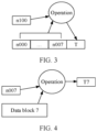
- FIG. 3 and FIG. 4 show a process of determining a value of a tag.
- a node corresponds to a counter in a parent node of the node.
- a tag of the node may be determined according to a preset operation rule based on a value of the corresponding counter in the parent node of the node and a value of each counter in the node.
- the node n00 corresponds to a counter n100 in the parent node n10. In this way, as shown in FIG.
- a value of a tag T of the node n00 may be obtained according to the preset operation rule based on a value of the counter n100 and values of counters n000 to n007 in the node n10.
- each data block also corresponds to a tag T.
- a process of determining a value of a tag of a data block is similar to a process of determining a value of a tag of a node.
- one data block corresponds to one counter in a leaf node.
- the data block 7 corresponds to the counter n007 in the leaf node n00.
- a value of a tag of a data block may be determined according to a preset operation rule based on a value of the counter corresponding to the data block and data in the data block. For example, as shown in FIG. 4 , the value of the tag T7 corresponding to the data block 7 is obtained according to the preset operation rule based on the data stored in the data block 7 and the value of the counter n007 corresponding to the data block 7.
- the operation rule used for determining a tag may be a hash (hash) operation, or may be a MAC operation, that is, a value of the tag may be a MAC value.
- FIG. 5A and FIG. 5B are another schematic diagram of a data structure of a counter integrity tree according to an embodiment of this application.
- the integrity tree includes five layers. It is assumed that a tag of each node is a message authentication code (MAC).
- a root node b33 is used as an example.
- a root counter corresponding to the root node b33 is a root counter 11, the root node b33 includes eight counters and a MAC 10, and the eight counters are respectively denoted as C0 to C7.
- the MAC 10 is obtained through calculation by using a MAC function based on the root counter 11 and values of eight counters C0 to C7 of the root node b33.
- the eight counters of the root node b33 are respectively in one-to-one correspondence with eight sub-nodes b20 to b27 of the root node b33.
- the node b20 corresponds to the counter C0 of the root node b33
- the node b21 corresponds to the counter C1 of the root node b33
- the node b27 corresponds to the counter C7 of the root node b33.
- Each of the sub-nodes b20 to b27 includes eight counters and one MAC.
- the sub-node b20 includes eight counters C00 to C07 and a MAC 20.
- the MAC 20 is obtained through calculation by using the MAC function based on the counter C0 of the root node b33 and the eight counters C00 to C07 of the sub-node b20.
- a MAC 27 of the sub-node b27 is obtained through calculation by using the MAC function based on the counter C7 of the root node b33 and eight counters C70 to C77 of the sub-node b27.
- a MAC 30 of a sub-node b10 is obtained through calculation by using the MAC function based on the counter C00 of the node b20 and eight counters C000 to C007 of the node b 10
- a MAC 37 of a sub-node b17 is obtained through calculation by using the MAC function based on the counter C07 of the node b20 and eight counters C070 to C077 of the node b17
- a MAC 40 of a sub-node b00 is obtained through calculation by using the MAC function based on the counter C000 of the node b10 and eight counters C0000 to C0007 of the node b00
- a MAC 47 of a sub-node b07 is obtained through calculation by using the MAC function based on the counter C007 of the node b 10 and eight counters C0070 to C0077 of the node b07.
- each leaf node includes eight counters and one MAC.
- a leaf node v0 is used as an example.
- the leaf node v0 includes eight counters C00000 to C00007 and a MAC 50.
- the MAC 50 is obtained through calculation by using the MAC function based on the counter C0000 of the sub-node b00 and the eight counters C00000 to C00007 of the leaf node v0.
- the eight counters of the leaf node v0 respectively correspond to eight data blocks in the memory, and each data block corresponds to one MAC.
- a MAC 60 of a data block 70 is obtained through calculation by using the MAC function based on the counter C00000 and data 000 in the data block 70
- a MAC 67 of a data block 77 is obtained through calculation by using the MAC function based on the counter C00007 and data 007 in the data block 77.
- the tag T and the MAC each may be understood as a Nonce.
- a MAC used to verify integrity of data in a data block is maintained by a leaf node corresponding to the data block
- a MAC used to verify integrity of a leaf node is maintained by a parent node of the leaf node. Integrity of the parent node may be maintained by using another parent node in the tree. The rest is deduced by analogy, until the root node is verified.
- each time data is written into a data block a value of a corresponding counter in the integrity tree is incremented or updated. For example, when data is written into the data block 70, and the data in the data block 70 is updated, a value of the counter C00000 in the leaf node v0 corresponding to the data block 70 is incremented, for example, increased by 1. Incrementing the value of the counter C00000 in the leaf node v0 triggers recalculation of the MAC of the leaf node v0.
- data 000 in the data block 70 is read.
- the MAC 60 of the data block 70 is verified.
- the counter C00000 in the leaf node v0 is read, a value 1 is obtained through calculation by using the MAC function based on a value of the counter C00000 and the data 000, and the value 1 obtained through calculation is matched with a value 2 of the MAC 60 stored in the data block 70. If the stored value 2 does not match the value 1 obtained through calculation, it indicates that the data 000 is tampered with. If the stored value 2 matches the calculated value 1, integrity of the leaf node v0 continues to be verified.
- a parent node (that is, the node b00) of the leaf node v0 is read, and a calculated MAC of the leaf node v0 is obtained through calculation by using the MAC function based on a value of a counter (that is, the counter C0000) corresponding to the leaf node v0 in the node b00 and the values of the eight counters of the leaf node v0.
- the calculated MAC of the leaf node v0 is matched with the stored MAC of the leaf node v0. If the stored MAC of the leaf node v0 does not match the calculated MAC of the leaf node v0, it indicates that the leaf node v0 is tampered with, and the integrity verification of the data 000 fails.
- the integrity of the parent node (that is, the node b00) of the leaf node v0 continues to be verified. The rest is deduced by analogy, until the root node b33 is verified. If it is verified that the stored MAC of the root node b33 matches a calculated MAC of the root node b33, it indicates that the data 000 is not tampered with.
- FIG. 5A and FIG. 5B show that a tag of a data block and corresponding data are stored in a same cache line.
- a tag of a data block and corresponding data may be separately stored.
- a MAC of the node and a plurality of counters of the node are stored in a same cache line, to ensure the integrity of the node.
- a MAC of a node is stored together.
- FIG. 6 FIG.
- a MAC of a node may be separately stored, that is, the MAC of the node may be divided into a plurality of parts for separate storage.
- the MAC of the node is divided into eight equal parts, and the eight parts are stored together with eight counters of the node in a one-to-one correspondence, where each counter occupies 56 bits.
- a size of the MAC shown in FIG. 6 is 56 bits.
- the 56-bit MAC is divided into eight equal parts, and each part is 8 bits, where 7 bits of the 8 bits are used and 1 bit is not used.
- the size of the MAC includes but is not limited to 56 bits, and the MAC may not be stored in equal parts during partitioning.
- the MAC function in FIG. 5A and FIG. 5B may be a one-way cryptographic function such as AES-GCM or SHA-256.
- one data block corresponds to one counter, and each time data is written into a data block, a counter corresponding to the data block is increased by 1.
- access frequencies of the processor for different data blocks are different. For example, a quantity of times of writing data into a data block 1 is greater than a quantity of times of writing data into a data block 2. In this case, the data block 1 requires a larger storage resource of a counter than the data block 2.
- the counter corresponding to the data block 1 needs a 30-bit storage resource to record a quantity of times of performing a write operation on the data block 1 and prevent overflow
- the counter corresponding to the data block 2 only needs a 10-bit storage resource to record a quantity of times of performing a write operation on the data block 2.
- storage resources of counters corresponding to different data blocks are the same.
- a storage resource of each counter is 50 bits.
- a shared counter is set.
- the shared counter includes at least two sub-counters, and the at least two sub-counters share a storage resource of the shared counter.
- a size of a shared storage resource of each sub-counter may be dynamically adjusted based on an access status of a data block. For example, a sub-counter 1 occupies, at a first time, 30-bit storage resource of a shared counter to which the sub-counter 1 belongs.
- a storage resource of the sub-counter 1 may be adjusted from 30 bits to 40 bits, thereby dynamically adjusting a storage resource of each sub-counter, reducing an overflow probability of a counter corresponding to a data block with a high access frequency, improving utilization of a storage resource of a counter, and improving performance of data integrity verification.
- FIG. 7 is a schematic diagram of a computing system with an integrity protection mechanism according to an embodiment of this application.
- the computer system includes a processor and a DRAM (main memory).
- the processor is trustworthy, and the DRAM is untrustworthy.
- data in the processor cannot be attacked or tampered with by an attacker. Therefore, an edge of the processor may be used as a trust boundary.
- Data in the DRAM may be arbitrarily attacked or tampered with by an attacker.
- data in the main memory or data on a physical channel between the main memory and the processor may be intercepted or tampered with.
- the processor and the main memory are communicatively connected by using a bus, for example, by using a bus.
- the data in the DRAM needs to be encrypted, so that the attacker cannot read the data in the DRAM.
- integrity verification needs to be performed on the data each time the data is read from the DRAM.
- the processor includes a computing core (for example, a CPU core), a first cache, an integrity tree root node (Merkle tree root), an integrity protection and control unit (Memory Integrity Controller), and an integrity tree cache (Merkle tree cache).
- a computing core for example, a CPU core
- a first cache for example, a CPU core
- an integrity tree root node for example, a CPU core
- an integrity protection and control unit for example, a CPU core
- Merkle tree cache an integrity tree cache
- the first cache may include a plurality of levels of caches, for example, include a cache L1, a cache L2, and a cache L3.
- the first cache is used to cache data, for example, cache data read from a main memory, where the data in the first cache is data on which integrity verification succeeds.
- the processor first queries the first cache for the target data. Specifically, the processor queries the cache L1 for the target data, queries the cache L2 for the target data if the target data is not found in the cache L1, and queries the cache L3 for the target data if the target data is not found in the cache L2. After finding the target data in the first cache, the processor directly returns the found target data.
- the processor does not find the target data in the first cache, the processor reads the target data from the main memory, and performs integrity verification on the target data.
- the integrity tree root node is the root of the integrity tree. Private data that cannot be tampered with externally is stored in the processor, to prevent the root node from being read or tampered with by an attacker, thereby ensuring reliability and accuracy of data integrity verification.
- Integrity tree cache In a general-purpose system, data of sub-nodes of an integrity tree is usually stored in a main memory, and an access speed is relatively slow.
- the integrity tree cache can cache data of the integrity tree that is recently accessed, so as to accelerate an access speed and improve performance.
- the integrity tree cache caches one or more sub-nodes of the integrity tree that are read during the previous integrity verification.
- the processor first queries the integrity tree cache for a required sub-node, for example, a node 1. If the node 1 is found in the integrity tree cache, the node 1 is directly used to perform the integrity verification, without being read from the main memory, thereby improving the speed of integrity verification.
- an integrity tree cache caches a leaf node v00, a node b16, and a node b22.
- the processor reads data 000 in a data block 70 and a MAC 60 corresponding to the data 000 from the main memory, and then performs integrity verification on the data 000.
- the processor determines, based on a correspondence between a data block and a leaf node, that the data block 70 corresponds to the leaf node v00. Then, the processor queries the integrity tree cache to determine whether the leaf node v00 is cached. If the leaf node v00 is found in the integrity tree cache, the processor calculates, by using a MAC function based on counters C00000 to C00007 of the leaf node v00 and the read data 000, a MAC corresponding to the data 000, and records the MAC as a MAC 6. The processor matches the calculated MAC 6 with a MAC 60 read from the main memory.
- the processor If the MAC 6 matches the MAC 60, it indicates that the data 000 is not tampered with, the integrity verification succeeds, and integrity verification does not need to be performed on the leaf node v00. If the processor does not find the leaf node v00 in the integrity tree cache, the processor reads the leaf node v00 from the main memory, and determines, based on the foregoing method, whether the calculated MAC 6 matches the MAC 60 read from the main memory. If the MAC 6 matches the MAC 60, the processor reads a parent node of the leaf node v00 from the main memory, to verify integrity of the leaf node v00. The rest is deduced by analogy, until the root node is verified.
- the processor further includes an encryption engine (memory encryption engine, MEE).
- MEE memory encryption engine
- the MEE is configured to encrypt plaintext based on a counter, and is further configured to decrypt ciphertext read from the main memory. This can prevent malicious observers from reading data in the main memory.
- An encryption key used for encryption and decryption may be stored in the processor, for example, stored in a register in the processor.
- An encryption or decryption method used by the encryption engine is not limited in embodiments of this application.
- the DRAM includes a memory protection region, integrity tree (Merkle Tree) data, and a non-memory protection region (Normal Region).
- integrity tree Merkle Tree
- Normal Region non-memory protection region
- the memory protection region is a memory region on which integrity protection is performed in the main memory.
- the data block in embodiments of this application is a data block corresponding to the memory protection region.
- Non-memory protection region a memory region without integrity protection in the main memory.
- Integrity tree data is data used to protect an integrity tree of the main memory.
- the data is stored in the main memory, or may be stored in another storage component, for example, a CPU chip.
- the main memory includes ciphertext data, where password data is data encrypted by the encryption engine.
- the processor controls the encryption engine to encrypt plaintext data to obtain ciphertext data, and stores the ciphertext data in the main memory. After being read by an attacker, the ciphertext data cannot be decrypted, thereby preventing a malicious observer from reading data in the main memory.
- the main memory further includes plaintext data.
- the plaintext data is data that is not encrypted, and an attacker may randomly read the plaintext data.
- the plaintext data is stored in the non-memory protection region of the main memory.
- the processor first queries, in the first cache, whether target data that is to be read is cached, and if the target data is cached in the first cache, directly reads the target data from the first cache. If the target data is not found in the first cache, the target data is read from the main memory. Specifically, the ciphertext data of the target data is read from the memory protection region of the main memory, and is decrypted and stored in the first cache. To verify integrity of the target data, the processor queries the integrity tree cache to determine whether an integrity tree node corresponding to the target data exist. If the integrity tree node exists, the processor uses the integrity tree node to verify the integrity of the target data.
- the processor If the processor does not find the integrity tree node corresponding to the target data in the integrity tree cache, the processor reads the integrity tree node, for example, a node 1, corresponding to the target data from the integrity tree data of the main memory, and uses the node 1 to calculate a MAC of the target data. If the calculated MAC matches a stored MAC of the target data, integrity of the node 1 continues to be verified. The rest is deduced by analogy, until the corresponding root node is verified.
- the integrity tree node for example, a node 1, corresponding to the target data from the integrity tree data of the main memory
- the computing core In a write process of data, the computing core writes the target data into a corresponding data block in the memory protection region, and simultaneously updates a value of a counter and a MAC value that correspond to the data block.
- a resource allocation method provided in embodiments of this application is described in detail with reference to FIG. 8 .
- FIG. 8 is a schematic flowchart of a resource allocation method according to an embodiment of this application. As shown in FIG. 8 , the apparatus in embodiments of this application includes the following steps.
- S101 Obtain, in response to a write request for a target data block, a value of a first sub-counter corresponding to the target data block in an integrity tree.
- the first sub-counter is a sub-counter of a first shared counter, and a first storage resource of the first sub-counter belongs to a storage resource of the first shared counter.
- FIG. 9 is a schematic diagram of a structure of an integrity tree according to an embodiment of this application. The following describes in detail the integrity tree according to embodiments of this application with reference to FIG. 9 .
- a conventional integrity tree counter with a fixed width is changed to a counter whose width can be dynamically adjusted.
- the width herein may be understood as a storage resource of the counter.
- one shared counter includes two or more sub-counters, and the two or more sub-counters share a storage resource of the shared counter.
- one node includes a plurality of shared counters (Share Counter).
- the node includes eight shared counters, each shared counter may be shared by a plurality of sub-counters, and partitioning of a storage resource of a shared counter may be dynamically adjusted according to a requirement of sub-counters.
- Each sub-counter of a leaf node corresponds to one data block.
- FIG. 10 is a schematic diagram of a structure of a shared counter.
- the shared counter includes n sub-counters, and the n sub-counters share a storage resource of the shared counter.
- the storage resource of the shared counter is 50 bits
- the n sub-counters share the 50-bit storage resource. It is assumed that n is 2, and the two sub-counters are respectively denoted as a sub-counter 1 and a sub-counter 2.
- the sub-counter 1 occupies 12 bits in the 50-bit storage resource of the shared counter
- the sub-counter 2 occupies 35 bits in the 50-bit storage resource of the shared counter.
- the processor receives a write request for a target data block, where the write request is used to request to write data into the target data block. After receiving the write request for the target data block, the processor obtains a value of a first sub-counter corresponding to the target data block in the integrity tree. For example, it is assumed that the target data block is a data block 0 in FIG. 9 . When receiving a write request for the target data block, the processor obtains a value of a first sub-counter corresponding to the target data block. It is assumed that the obtained value of the first sub-counter is 111111111111.
- S102 Allocate a second storage resource to the first sub-counter when it is detected that a value obtained after a first value is added to the value of the first sub-counter is greater than a maximum storage value of the first storage resource.
- the second storage resource also belongs to the storage resource of the first shared counter.
- the first shared counter includes two sub-counters: a first sub-counter and a second sub-counter, and the first sub-counter and the second sub-counter share a storage resource of the first shared counter.
- storage resources of the first sub-counter and the second sub-counter both belong to the storage resource of the first shared counter, and a storage resource of the first sub-counter does not overlap a storage resource of the second sub-counter.
- Table 1 Allocation manner 1 12 35 Allocation manner 2 16 31 ... ... ...
- Table 1 shows m allocation manner of the storage resource of the first shared counter. For example, in an allocation manner 1, when the first sub-counter occupies a 12-bit storage resource of the first shared counter, the second sub-counter occupies a 35-bit storage resource of the shared counter. In an allocation manner 2, when the first sub-counter occupies a 20-bit storage resource of the first shared counter, the second sub-counter occupies a 27-bit storage resource of the first shared counter.
- the processor when writing data into the target data block, the processor obtains a value of a first sub-counter corresponding to the target data block, and determines whether a value obtained after a first value is added to the value of the first sub-counter is greater than a maximum storage value of the first storage resource that is currently allocated to the first sub-counter, where the first value is a positive integer.
- the value of the first sub-counter obtained by the processor is 111111111111
- the first sub-counter occupies a 12-bit storage resource of the first shared counter, that is, a size of the first storage resource is 12 bits.
- the processor After adding the first value to the value of the first sub-counter, the processor determines that a value obtained after the first value is added to the value of the first sub-counter is greater than a maximum storage value of the first storage resource, that is, 111111111111. In this case, it indicates that the first sub-counter overflows, and the first storage resource currently allocated to the first sub-counter cannot meet an actual requirement of the first sub-counter. In this case, the processor allocates a second storage resource to the first sub-counter. In this case, a storage resource of the first sub-counter is a sum of the first storage resource and the second storage resource. For example, as shown in Table 2, a 4-bit storage resource is further allocated to the first sub-counter, so that the adjusted storage resource of the first sub-counter is 16 bits. In this way, the storage resource of the first sub-counter is increased, thereby further preventing overflow of the first sub-counter and improving performance of data integrity verification of the integrity tree.
- the second storage resource is allocated to the first sub-counter, so as to dynamically adjust the storage resource of the first shared counter according to a requirement of a storage resource of a sub-counter, thereby improving utilization of the storage resource of the first shared counter.
- the second storage resource may be an idle storage resource that is not allocated in the first shared counter.
- the first shared counter further includes a second sub-counter
- a storage resource of the second sub-counter is denoted as a third storage resource
- the third storage resource also belongs to the storage resource of the first shared counter.
- the first sub-counter and the second sub-counter share the storage resource of the first shared counter.
- the second storage resource includes an idle storage resource that is not used in the third storage resource.
- the second storage resource includes an idle storage resource that is not allocated in the first shared counter and an idle storage resource that is not used in the third storage resource.
- an embodiment of this application further includes adjusting the third storage resource, so that a difference between the third storage resource before the adjustment and the third storage resource after the adjustment is equal to the second storage resource.
- a value of a first sub-counter corresponding to the target data block in an integrity tree is obtained, where the first sub-counter is a sub-counter of a first shared counter, and a first storage resource of the first sub-counter belongs to a storage resource of the first shared counter.
- a second storage resource is allocated to the first sub-counter when it is detected that a value obtained after a first value is added to the value of the first sub-counter is greater than a maximum storage value of the first storage resource, so as to implement dynamic adjustment of the storage resource of the first shared counter, thereby improving utilization of the storage resource of the first shared counter.
- the adjusted storage resource of the first sub-counter is increased, thereby further preventing overflow of the first sub-counter and improving performance of data integrity verification of the integrity tree.
- a shared counter in addition to the at least two sub-counters, a shared counter further includes a resource partitioning identifier (for example, Metadata), and the resource partitioning identifier indicates a storage resource of a sub-counter.
- the first shared counter belongs to the shared counter to be described in embodiments of this application.
- the first shared counter in addition to the first sub-counter and the second sub-counter, the first shared counter further includes a resource partitioning identifier, and the resource partitioning identifier indicates a storage resource of the first sub-counter and/or the second sub-counter.
- resource partitioning manners There may be different resource partitioning manners. The following describes two resource partitioning manners: continuous resource partitioning and discontinuous resource partitioning.
- Manner 1 is the continuous resource partitioning. In this partitioning manner, a resource partitioning granularity is relatively small.
- a shared counter includes two sub-counters, which are denoted as a sub-counter 1 and a sub-counter 2.
- a storage resource of the shared counter is 50 bits, and a resource partitioning granularity is 1 bit.
- a resource partitioning identifier needs to be represented by 6 bits, and the sub-counter 1 and the sub-counter 2 share 44 bits. Different correspondences between a resource partitioning identifier and each storage resource are shown in Table 2.
- Table 2 Resource partitioning identifier Size of storage resource of sub-counter 1 (bits) Size of storage resource of sub-counter 2 (bits) 000000 1 43 000001 2 42 000010 3 41 000011 4 40 ... ... ...
- a resource partitioning identifier 000001 indicates that the sub-counter 1 occupies a storage resource of the shared counter as follows: Starting from the 7 th bit from the left, the sub-counter 1 occupies a 2-bit storage resource of the shared counter, and the sub-counter 2 occupies the remaining 42-bit storage resource of the shared counter.
- Table 2 is merely an example of continuous resource partitioning in embodiments of this application, and a resource partitioning manner of the shared counter in embodiments of this application includes but is not limited to that shown in Table 2.
- Manner 2 is discontinuous resource partitioning.
- the resource partitioning identifier occupies a relatively few storage resource of the shared counter.
- a shared counter includes two sub-counters, which are denoted as a sub-counter 1 and a sub-counter 2.
- a storage resource of the shared counter is 50 bits, and there are eight types of preset resource allocation manners. In this case, 3 bits are needed to identify the eight types of resource allocation manners, that is, the resource partitioning identifier needs to be represented by 3 bits, and the sub-counter 1 and the sub-counter 2 share 47 bits.
- Table 3 Resource partitioning identifier Size of storage resource of sub-counter 1 (bits) Size of storage resource of sub-counter 2 (bits) 000 12 35 001 16 31 010 20 27 011 23 24 100 24 23 101 27 20 110 31 16 111 35 12
- a resource partitioning identifier 101 indicates that the sub-counter 1 occupies a storage resource of the shared counter as follows: Starting from the 4 th bit from the left, the sub-counter 1 occupies a 20-bit storage resource of the shared counter, and the sub-counter 2 occupies the remaining 27-bit storage resource of the shared counter.
- Table 3 is merely an example of discontinuous resource partitioning in embodiments of this application, and a resource partitioning manner of the shared counter in embodiments of this application includes but is not limited to that shown in Table 3.
- differences between sizes of storage resources of a same sub-counter corresponding to two adjacent resource partitioning identifiers are the same.
- a difference between sizes of storage resources of the sub-counter 1 corresponding to a resource partitioning identifier 000000 and a resource partitioning identifier 00001 that are adjacent is 1 bit
- a difference between sizes of storage resources of the sub-counter 1 corresponding to a resource partitioning identifier 000001 and a resource partitioning identifier 00010 that are adjacent is 1 bit.
- a difference between sizes of storage resources of the sub-counter 2 corresponding to the resource partitioning identifier 000000 and the resource partitioning identifier 00001 that are adjacent is 1 bit
- a difference between sizes of storage resources of the sub-counter 2 corresponding to the resource partitioning identifier 000001 and the resource partitioning identifier 00010 that are adjacent is 1 bit.
- differences between sizes of storage resources of a same sub-counter corresponding to two adjacent resource partitioning identifiers are different.
- a difference between sizes of storage resources of the sub-counter 1 corresponding to a resource partitioning identifier 010 and a resource partitioning identifier 011 that are adjacent is 3 bits, and a difference between sizes of storage resources of the sub-counter 1 corresponding to a resource partitioning identifier 011 and a resource partitioning identifier 100 that are adjacent is 1 bit.
- a difference between sizes of storage resources of the sub-counter 2 corresponding to the resource partitioning identifier 010 and the resource partitioning identifier 011 that are adjacent is 3 bits, and a difference between sizes of storage resources of the sub-counter 2 corresponding to the resource partitioning identifier 011 and the resource partitioning identifier 100 that are adjacent is 1 bit.
- a data structure of the shared counter is related to a quantity of sub-counters included in the shared counter.
- the shared counter includes two sub-counters and one resource partitioning identifier, where the resource partitioning identifier indicates a storage resource of at least one of the two sub-counters, and a total storage resource that is of the shared counter and that is occupied by the two sub-counters is equal to a remaining storage resource in the storage resource of the shared counter except a storage resource occupied by the resource partitioning identifier.
- the shared counter is a first shared counter
- the first shared counter includes a first sub-counter, a second sub-counter, and a resource partitioning identifier
- the resource partitioning identifier indicates a storage resource of the first sub-counter and/or the second sub-counter.
- the shared counter includes one resource partitioning identifier and two sub-counters.
- the two sub-counters are a sub-counter 1 and a sub-counter 2.
- the sub-counter 1 corresponds to a data block 1 and is used to maintain data integrity of the data block 1.
- the sub-counter 2 corresponds to a data block 2 and is used to maintain data integrity of the data block 2.
- the shared counter has a storage resource with a total of 50 bits.
- the resource partitioning identifier occupies a y-bit storage resource of the shared counter 1
- the sub-counter 1 occupies an x-bit storage resource of the shared counter 1
- the sub-counter 2 occupies a (50-x-y)-bit storage resource of the shared counter 1. It is assumed that y is equal to 3.
- the sub-counter 1 occupies a 16-bit storage resource of the shared counter 1, that is, x is equal to 16, and the sub-counter 2 occupies a remaining 3 1-bit storage resource of the shared counter.
- the sub-counter 1 occupies a 20-bit storage resource of the shared counter 1, that is, x is equal to 20, and the sub-counter 2 occupies a remaining 27-bit storage resource of the shared counter.
- the processor may dynamically adjust a storage resource required by a sub-counter by selecting different resource partitioning identifiers, thereby improving utilization of the storage resource, reducing an overflow probability of the sub-counter, and improving performance of data integrity verification.
- the shared counter includes n sub-counters and n resource partitioning identifiers, where n is a positive integer greater than or equal to 3, the n resource partitioning identifiers are in a one-to-one correspondence with the n sub-counters, and each of the n resource partitioning identifiers indicates a storage resource of a corresponding sub-counter.
- the shared counter is a first shared counter.
- the first shared counter includes a first sub-counter, n-1 second sub-counters, and n resource partitioning identifiers.
- Each of the n resource partitioning identifiers indicates a storage resource of a corresponding sub-counter.
- the shared counter includes a plurality of sub-counters, and the plurality of sub-counters share the storage resource of the shared counter.
- the shared counter includes four resource partitioning identifiers and four sub-counters, where the four resource partitioning identifiers are respectively denoted as MD1, MD2, MD3, and MD4, and the four counters are respectively denoted as a sub-counter 1, a sub-counter 2, a sub-counter 3, and a sub-counter 4.
- the sub-counter 1 corresponds to a data block 1 and is used to maintain data integrity of the data block 1.
- the sub-counter 2 corresponds to a data block 2 and is used to maintain data integrity of the data block 2.
- the sub-counter 3 corresponds to a data block 3 and is used to maintain data integrity of the data block 3.
- the sub-counter 4 corresponds to a data block 4 and is used to maintain data integrity of the data block 4.
- the shared counter has a storage resource with a total of 50 bits.
- the four resource partitioning identifiers respectively occupy a 2-bit storage resource of the shared counter, and the four sub-counters share a remaining 32-bit storage resource of the shared counter.
- Table 4 shows a resource partitioning manner according to an embodiment of this application. It should be noted that Table 4 is merely an example. A resource partitioning manner in embodiments of this application includes but is not limited to that shown in Table 4.
- Table 4 Resource partitioning identifier Size of resource of sub-counter (bits) 00 0 01 8 10 16 11 24
- a total storage resource that is of the shared counter and that is occupied by the n sub-counters is equal to a remaining storage resource in the storage resource of the shared counter except the storage resource occupied by the n resource partitioning identifiers.
- the shared counter includes four resource partitioning identifiers and four sub-counters, and a storage resource of the shared counter is 50 bits.
- Each of the four resource partitioning identifiers occupies a 2-bit storage resource, and the four resource partitioning identifiers occupy an 8-bit storage resource of the shared counter in total.
- a remaining 32-bit storage resource is shared by the four sub-counters. As shown in FIG. 14 , it is assumed that values in the shared counter are: 00011001 10000101 01010001 00110000 10001010. A value of each resource partitioning identifier is obtained by parsing the shared counter.
- a value of MD1 is 00, indicating that the sub-counter 1 occupies a 0-bit storage resource of the shared counter
- a value of MD2 is 01
- a value of MD3 is 10
- a value of MD4 is 01, indicating that the sub-counter 4 occupies an 8-bit storage resource of the shared counter.
- a total storage resource that is of the shared counter and that is occupied by the n sub-counters is less than a remaining storage resource in the storage resource of the shared counter except the storage resource occupied by the n resource partitioning identifiers.
- the shared counter includes four resource partitioning identifiers and four sub-counters, and a storage resource of the shared counter is 50 bits.
- Each of the four resource partitioning identifiers occupies a 2-bit storage resource, and the four resource partitioning identifiers occupy an 8-bit storage resource of the shared counter in total.
- a remaining 32-bit storage resource is shared by the four sub-counters. As shown in FIG. 15 , it is assumed that values in the shared counter are: 01010010 10000101 01010001 00000000 10001010. A value of each resource partitioning identifier is obtained by parsing an 8-bit resource partitioning identifier.
- a value of MD1 is 01, indicating that the sub-counter 1 occupies an 8-bit storage resource of the shared counter
- a value of MD2 is 01
- a value of MD3 is 00
- a value of MD4 is 01, indicating that the sub-counter 4 occupies an 8-bit storage resource of the shared counter.
- the four sub-counters occupy a 24-bit storage resource of the shared counter in total, and the shared counter has an 8-bit idle storage resource.
- the processor may parse the shared counter by using at least two threads, to obtain a value of a sub-counter corresponding to each of the n resource partitioning identifiers. As shown in FIG. 14 and FIG. 15 , the processor starts two threads (a thread 1 and a thread 2) to perform parsing from two ends of the shared counter 2. For example, the thread 1 starts parsing from a left end of the shared counter, and the thread 2 starts parsing from a right end of the sub-counter, so as to quickly obtain a value of each sub-counter.
- the thread 1 and the thread 2 need to first parse values of the resource partitioning identifiers. Specifically, the thread 1 parses the values of the resource partitioning identifiers from the left side of a storage location of the resource partitioning identifiers. The thread 2 starts to parse the values of the resource partitioning identifier from the right side of the storage location of the resource partitioning identifiers.
- the sub-counter 1 occupies an 8-bit storage resource of the shared counter
- the sub-counter 2 occupies an 8-bit storage resource of the shared counter
- the sub-counter 3 occupies a 0-bit storage resource of the shared counter
- the sub-counter 4 occupies an 8-bit storage resource of the shared counter.
- the thread 1 offsets by 8 bits from the 9 th bit from the left end, to obtain a value of the sub-counter 1 as 10000101, offsets by 8 bits to the right from the 17 th bit, to obtain a value of the sub-counter 2 as 01010001.
- the thread 2 offsets by 8 bits to the left from the right end, to obtain a value of the sub-counter 4 as 10001010, and obtain a value of the sub-counter 3 as 0.
- a distance between storage addresses, in a storage device, of data blocks corresponding to two adjacent sub-counters is a preset value.
- the first shared counter is used as an example. As shown in FIG. 16 , it is assumed that the first shared counter includes a sub-counter 1 and a sub-counter 2, where the target data block is a data block 1 in FIG. 16 , and the second data block is a data block 2 in FIG. 16 .
- the data block 1 is adjacent to the data block 2, that is, a storage address of the target data block is adjacent to a storage address of the second moment block.
- the storage address of the data block herein refers to a storage address of the data block in a storage device (for example, a memory).
- the first shared counter is used as an example. As shown in FIG. 17 , it is assumed that the first shared counter includes a sub-counter 1 and a sub-counter 2, the target data block is a data block 1 in FIG. 17 , and the second data block is a data block p in FIG. 17 . A distance between a storage address of the data block 1 and a storage address of the data block 2 is longest. During actual program running, there is a specific rule of data access, and a quantity of times of data access between adjacent addresses are usually close. Therefore, requirements for counter resources are usually close. However, data blocks whose addresses with distant addresses are mapped to adjacent sub-counters, and the quantity of times of access of data blocks with distant addresses is less correlated. In this way, utilization of the shared storage resource can be maximized.
- the shared counter when the shared counter includes the resource partitioning identifier, a data structure of the shared counter is described in detail. Based on this, the resource partitioning method provided in embodiments of this application is further described with reference to FIG. 18 .
- FIG. 18 is another schematic flowchart of a resource partitioning method according to an embodiment of this application. Based on FIG. 11 to FIG. 17 , as shown in FIG. 18 , the method in embodiments of this application includes the following steps.
- S201 Obtain a first shared counter in response to a write request for a target data block.
- a processor receives a write request for a target data block, obtains a first sub-counter corresponding to the target data block, and obtains a first shared counter to which the first sub-counter belongs.
- the target data block is a data block 1.
- a corresponding first sub-counter is a sub-counter 1
- the sub-counter 1 belongs to a shared counter 1.
- the shared counter 1 is denoted as a first shared counter.
- S202 Obtain a first resource partitioning identifier corresponding to the first sub-counter from the first shared counter. Specifically, the processor parses the first shared counter to obtain a first resource partitioning identifier corresponding to the first sub-counter in the first shared counter. For example, the first resource partitioning identifier corresponding to the first sub-counter obtained through parsing is b001 in Table 3.
- S203 Obtain a first storage resource based on the first resource partitioning identifier and a preset correspondence between a resource partitioning identifier and a storage resource.
- S204 Parse out a value of the first sub-counter from the first shared counter based on the first storage resource.
- the processor searches the preset correspondence between a resource partitioning identifier and a storage resource for a storage resource corresponding to the first resource partitioning identifier based on the obtained first resource partitioning identifier, denotes the storage resource as the first storage resource, and obtains a value of the first sub-counter corresponding to the first storage resource in the first shared counter.
- the first shared counter has a 50-bit storage resource, and a value of the storage resource is 001 1111111111111111 0000000000000011100001000000100, where the leftmost 3 bits are the storage resource occupied by the first resource partitioning identifier, and the value of the first resource partitioning identifier is 001.
- Table 3 it may be found that the first storage resource corresponding to 001 is 16 bits, that is, the first sub-counter occupies a 16-bit storage resource of the first shared counter at a current moment, and the value of the first sub-counter is 1111111111111111.
- S205 Obtain, based on the first storage resource and the preset correspondence between a resource partitioning identifier and a storage resource, a storage resource corresponding to a second resource partitioning identifier when it is detected that a value obtained after a first value is added to the value of the first sub-counter is greater than a maximum storage value of the first storage resource.
- the storage resource corresponding to the second resource partitioning identifier is greater than the first storage resource.
- S206 Determine a size of the second storage resource based on a size of the storage resource corresponding to the second resource partitioning identifier and a size of the first storage resource.
- S207 Obtain, based on the size of the second storage resource, the second storage resource from an idle storage resource that is not used in a third storage resource, and allocate the second storage resource to the first sub-counter. Specifically, after obtaining the value of the first sub-counter according to the foregoing step, the processor determines whether a value obtained after a first value is added to the value of the first sub-counter is greater than a maximum storage value of the first storage resource. Still refer to the foregoing example. It is assumed that the first storage resource is 16 bits, the maximum storage value of the first storage resource is 1111111111111111, and the value of the first sub-counter at the current moment is also 1111111111111111.
- the storage resource of the first sub-counter is dynamically adjusted, that is, the second storage resource is added based on the first storage resource, so as to increase the storage resource of the first sub-counter, thereby reducing an overflow frequency of the first sub-counter.
- a storage resource corresponding to a second resource partitioning identifier is obtained based on the first storage resource and the preset correspondence between a resource partitioning identifier and a storage resource, where the storage resource corresponding to the second resource partitioning identifier is greater than the first storage resource.
- a size of the second storage resource is determined based on a size of the storage resource corresponding to the second resource partitioning identifier and a size of the first storage resource, and the second storage resource is obtained based on the size of the second storage resource from an idle storage resource that is not used in a third storage resource, and is allocated to the first sub-counter.
- any value of 20 bits, 23 bits, 24 bits, and 27 bits may be selected for the second storage resource.
- the second resource partitioning identifier b011 is used, and a storage resource corresponding to the second resource partitioning identifier b011 is 23 bits.
- the processor obtains the second storage resource from an idle storage resource that is not used in a third storage resource, and allocates the second storage resource to the first sub-counter. In this way, the processor adjusts the storage resource of the first sub-counter from 16 bits to 23 bits, and correspondingly adjusts the storage resource of the second sub-counter from 31 bits to 24 bits.
- the first resource partitioning identifier and the second resource partitioning identifier are two adjacent resource partitioning identifiers in the correspondence. Still refer to Table 3. If the first resource partitioning identifier is b001, the second resource partitioning identifier is b010.
- the first resource partitioning identifier in the first shared counter is replaced with the second resource partitioning identifier.
- the processor allocates the second storage resource to the first sub-counter, and simultaneously, the processor replaces the first resource partitioning identifier in the first shared counter with the second resource partitioning identifier.
- the processor may obtain the second resource partitioning identifier from the first shared counter, accurately determine the storage resource of the first sub-counter based on the second resource partitioning identifier, and accurately read the value of the first sub-counter from the first shared counter for data integrity verification.
- the adjusted first storage resource is 23 bits
- the corresponding second resource partitioning identifier is b011.
- the first resource partitioning identifier b001 in the first shared counter is replaced with the second resource partitioning identifier b011, and a value of the first shared counter after replacement is 011 00000001111111111111111 000000011100001000000100, where the first sub-counter occupies a 23-bit storage resource of the first shared counter, the value of the first sub-counter is 00000001111111111111, the second sub-counter occupies a 24-bit storage resource of the first shared counter, and the value of the second sub-counter is 000000011100001000000100.
- the processor allocates the second storage resource to the first sub-counter according to the foregoing steps, so that the storage resource of the first sub-counter is increased. In this way, when the first value is added to the value of the first sub-counter, the first sub-counter does not overflow, so that the first sub-counter can accurately record one write operation performed by the processor on the target data block.
- S209 Determine a MAC value of the target data block based on the value of the first sub-counter after addition.
- the processor adds the first value to the value of the first sub-counter
- the value of the first sub-counter corresponding to the target data block changes.
- the MAC value of the target data block needs to be recalculated by using a MAC calculation function based on the updated value of the first sub-counter and the data in the target data block.
- the processor when the first shared counter includes a resource partitioning identifier, the processor obtains the first shared counter in the integrity tree in response to a write request for a target data block, obtains a first resource partitioning identifier corresponding to a first sub-counter from the first shared counter, and obtains a value of the first sub-counter in the first shared counter based on the first resource partitioning identifier and a preset correspondence between a resource partitioning identifier and a storage resource.
- the processor obtains, based on a first storage resource and the preset correspondence between a resource partitioning identifier and a storage resource, a storage resource corresponding to a second resource partitioning identifier when it is detected that a value obtained after a first value is added to the value of the first sub-counter is greater than a maximum storage value of the first storage resource, where the storage resource corresponding to the second resource partitioning identifier is greater than the first storage resource; determines a size of the second storage resource based on a size of the storage resource corresponding to the second resource partitioning identifier and a size of the first storage resource; obtains, based on the size of the second storage resource, the second storage resource from an idle storage resource that is not used in the third storage resource, and allocates the second storage resource to the first sub-counter; and adds the first value to the value of the first sub-counter, and determines a MAC value of the target data block based on the value of the first sub-counter after addition.
- the storage resource of the first sub-counter is adjusted from the storage resource corresponding to the first resource partitioning identifier to the storage resource corresponding to the second resource partitioning identifier, thereby increasing the storage resource of the first sub-counter, reducing an overflow probability of the first sub-counter, and improving resource utilization of the first shared counter.
- a second value is added to a value of an overflow counter of a first node in which the first shared counter is located, and both the values of the first sub-counter and the second sub-counter are set to a third value, where the second value is a positive integer, and the third value is a positive number.
- a value of the first shared counter is 001 1111111111111111 1000000000000011100001000000100, where a value of the first sub-counter is 1111111111111111, and a maximum storage value of the first storage resource is 1111111111111111.
- a value obtained after the first value is added to the value of the first sub-counter is greater than the maximum storage value that is of the first storage resource and that is currently allocated to the first sub-counter, and a value of the second sub-counter is 1000000000000011100001000000100. Therefore, it is determined that an idle storage resource that is not used in the third storage resource is allocated to the first sub-counter.
- a second value is added to a value of an overflow counter of a first node in which the first shared counter is located, for example, the second value is 1, and values of all sub-counters of the first shared counter are all set to a third value, that is, values of both the first sub-counter and the second sub-counter are set to the third value.
- a reset value of the first shared counter is 001 000000000000 00000000000000000000000.
- a value of the resource partitioning identifier in the first shared counter may also be set to the third value (for example, 0), and a resource partitioning manner is re-determined, for example, re-determined to be a resource partitioning manner corresponding to the resource partitioning identifier 010 in Table 3, that is, the first sub-counter occupies a 20-bit storage resource of the first shared counter, and the second sub-counter occupies a 27-bit storage resource of the first shared counter.
- values of counters other than the first shared counter and the overflow counter in the first node may also be set to the third value (for example, 0).
- a value of at least one counter in the first node changes.
- the value of the overflow counter and the value of the first shared counter in the first node change.
- a MAC value of the first node needs to be re-determined based on a reset value of each counter in the first node.
- the MAC value of the first node is obtained through corresponding running based on the reset value of each counter in the first node and a value of a counter corresponding to the first node in a parent node.
- one sub-counter corresponds to one data block
- a MAC value corresponding to the data block also changes. Therefore, in embodiments of this application, after the sub-counter is reset, a MAC value of the data block corresponding to the sub-counter needs to be re-determined based on a reset value of the sub-counter. Specifically, the MAC value of the data block is re-determined through corresponding running based on the reset value of the sub-counter and data in the data block.
- FIG. 19 is a schematic diagram of a structure of a resource allocation apparatus according to an embodiment of this application.
- the resource allocation apparatus 100 includes a processor 110.
- the processor 100 is configured to: obtain, in response to a write request for a target data block, a value of a first sub-counter corresponding to the target data block in an integrity tree, where the first sub-counter is a sub-counter of a first shared counter, a first storage resource of the first sub-counter belongs to a storage resource of the first shared counter, and the first shared counter is a shared counter of a leaf node corresponding to the target data block in the integrity tree; and allocate a second storage resource to the first sub-counter when it is detected that a value obtained after a first value is added to the value of the first sub-counter is greater than a maximum storage value of the first storage resource, where the second storage resource belongs to the storage resource of the first shared counter, and the first value is a positive integer.
- the first shared counter further includes a second sub-counter, a third storage resource of the second sub-counter belongs to the storage resource of the first shared counter, and the second storage resource includes an idle storage resource that is not used in the third storage resource.
- the first shared counter further includes a resource partitioning identifier, and the resource partitioning identifier indicates a storage resource of the first sub-counter.
- the processor 100 is specifically configured to: obtain the first shared counter in response to the write request for the target data block; obtain a first resource partitioning identifier from the first shared counter; obtain the first storage resource based on the first resource partitioning identifier and a preset correspondence between a resource partitioning identifier and a storage resource; and parse out the value of the first sub-counter from the first shared counter based on the first storage resource.
- the processor 100 is specifically configured to: obtain, based on the first storage resource and the preset correspondence between a resource partitioning identifier and a storage resource, a storage resource corresponding to a second resource partitioning identifier, where the storage resource corresponding to the second resource partitioning identifier is greater than the first storage resource; determine a size of the second storage resource based on a size of the storage resource corresponding to the second resource partitioning identifier and a size of the first storage resource; and obtain, based on the size of the second storage resource, the second storage resource from the idle storage resource that is not used in the third storage resource, and allocate the obtained second storage resource to the first sub-counter.
- the processor 100 is further configured to: add the first value to the value of the first sub-counter when the second storage resource is allocated to the first sub-counter; and determine a message authentication code MAC value of the target data block based on the value of the first sub-counter after addition.
- the processor 100 is further configured to: when it is detected that there is an unused idle storage resource in the storage resource of the second sub-counter, allocate the second storage resource in the unused idle storage resource to the first sub-counter.
- the processor 100 is further configured to: when it is detected that there is no unused idle storage resource in the storage resource of the second sub-counter and there is no idle storage resource that is not allocated in the first shared counter, add a second value to a value of an overflow counter of a first node in which the first shared counter is located, and set values of both the first sub-counter and the second sub-counter to a third value, where the second value is a positive integer, and the third value is a positive number.
- values of all counters other than the overflow counter in the first node are set to the third value when the values of the first counter and the second sub-counter are set to the third value.
- a distance between storage addresses, in a storage device, of data blocks corresponding to two adjacent sub-counters in the first shared counter is a preset value.
- the resource allocation apparatus in embodiments of this application may be configured to perform the technical solutions of the foregoing methods. Implementation principles and technical effects of the resource allocation apparatus are similar, and details are not described herein again.
- All or some of the foregoing embodiments may be implemented by using software, hardware, firmware, or any combination thereof.
- software is used to implement the embodiments, all or a part of the embodiments may be implemented in a form of a computer program product.
- the computer program product includes one or more computer instructions.
- the computer may be a general-purpose computer, a dedicated computer, a computer network, or another programmable apparatus.
- the computer instructions may be stored in a computer-readable storage medium or may be transmitted from a computer-readable storage medium to another computer-readable storage medium.
- the computer instructions may be transmitted from a website, computer, server, or data center to another website, computer, server, or data center in a wired (for example, a coaxial cable, an optical fiber, or a digital subscriber line (DSL)) or wireless (for example, infrared, radio, or microwave) manner.
- the computer-readable storage medium may be any usable medium accessible by the computer, or a data storage device, for example, a server or a data center, integrating one or more available media.
- the available medium may be a magnetic medium (for example, a floppy disk, a hard disk, or a magnetic tape), an optical medium (for example, a DVD), a semiconductor medium (for example, a solid-state disk Solid-State Disk (SSD)), or the like.
- a magnetic medium for example, a floppy disk, a hard disk, or a magnetic tape
- an optical medium for example, a DVD
- a semiconductor medium for example, a solid-state disk Solid-State Disk (SSD)
Landscapes
- Engineering & Computer Science (AREA)
- Theoretical Computer Science (AREA)
- Computer Security & Cryptography (AREA)
- Software Systems (AREA)
- General Engineering & Computer Science (AREA)
- General Physics & Mathematics (AREA)
- Physics & Mathematics (AREA)
- Signal Processing (AREA)
- Computer Networks & Wireless Communication (AREA)
- Power Engineering (AREA)
- Health & Medical Sciences (AREA)
- Bioethics (AREA)
- General Health & Medical Sciences (AREA)
- Computer Hardware Design (AREA)
- Storage Device Security (AREA)
- Information Retrieval, Db Structures And Fs Structures Therefor (AREA)
Applications Claiming Priority (1)
| Application Number | Priority Date | Filing Date | Title |
|---|---|---|---|
| PCT/CN2020/119755 WO2022067822A1 (zh) | 2020-09-30 | 2020-09-30 | 资源分配装置、装置与存储介质 |
Publications (2)
| Publication Number | Publication Date |
|---|---|
| EP4213053A1 true EP4213053A1 (de) | 2023-07-19 |
| EP4213053A4 EP4213053A4 (de) | 2023-11-01 |
Family
ID=80951166
Family Applications (1)
| Application Number | Title | Priority Date | Filing Date |
|---|---|---|---|
| EP20955842.8A Pending EP4213053A4 (de) | 2020-09-30 | 2020-09-30 | Ressourcenzuweisungsverfahren und -vorrichtung sowie speichermedium |
Country Status (4)
| Country | Link |
|---|---|
| US (1) | US12519653B2 (de) |
| EP (1) | EP4213053A4 (de) |
| CN (1) | CN116171443A (de) |
| WO (1) | WO2022067822A1 (de) |
Families Citing this family (4)
| Publication number | Priority date | Publication date | Assignee | Title |
|---|---|---|---|---|
| US12468707B1 (en) * | 2022-03-31 | 2025-11-11 | Amazon Technologies, Inc. | Down-sized cluster performance modeling for a tiered data processing service |
| US12216653B1 (en) | 2022-03-31 | 2025-02-04 | Amazon Technologies, Inc. | Thrashing detection and avoidance for a tiered data processing service |
| CN115269734B (zh) * | 2022-09-27 | 2022-11-29 | 北京奥星贝斯科技有限公司 | 分布式数据库的存储管理方法及装置 |
| CN119557260B (zh) * | 2025-01-26 | 2025-07-15 | 深圳市纽创信安科技开发有限公司 | 数据处理方法和数据处理芯片 |
Family Cites Families (26)
| Publication number | Priority date | Publication date | Assignee | Title |
|---|---|---|---|---|
| JPH01303527A (ja) * | 1988-05-31 | 1989-12-07 | Hitachi Ltd | 共有資源の管理方法 |
| WO2009061432A1 (en) * | 2007-11-06 | 2009-05-14 | Credit Suisse Securities (Usa) Llc | Predicting and managing resource allocation according to service level agreements |
| JP5159849B2 (ja) * | 2010-09-24 | 2013-03-13 | 株式会社東芝 | メモリ管理装置及びメモリ管理方法 |
| EP2726991B1 (de) * | 2011-06-29 | 2018-03-14 | Intel Corporation | Verfahren und vorrichtung zur verschlüsselung eines speichers mit einer integritätsprüfung und schutz gegen wiedergabeangriffen |
| WO2013100964A1 (en) * | 2011-12-28 | 2013-07-04 | Intel Corporation | Method and system for protecting memory information in a platform |
| US9053346B2 (en) | 2011-12-28 | 2015-06-09 | Intel Corporation | Low-overhead cryptographic method and apparatus for providing memory confidentiality, integrity and replay protection |
| CN102629236B (zh) * | 2012-02-22 | 2015-02-25 | 哈尔滨工程大学 | 基于不等长计数器的存储器保护方法 |
| US8819455B2 (en) | 2012-10-05 | 2014-08-26 | Intel Corporation | Parallelized counter tree walk for low overhead memory replay protection |
| JP6181004B2 (ja) * | 2014-06-20 | 2017-08-16 | 株式会社東芝 | メモリ管理装置、プログラム、及び方法 |
| US10185842B2 (en) | 2015-03-18 | 2019-01-22 | Intel Corporation | Cache and data organization for memory protection |
| US9798900B2 (en) | 2015-03-26 | 2017-10-24 | Intel Corporation | Flexible counter system for memory protection |
| US9710675B2 (en) | 2015-03-26 | 2017-07-18 | Intel Corporation | Providing enhanced replay protection for a memory |
| US9678894B2 (en) | 2015-03-27 | 2017-06-13 | Intel Corporation | Cache-less split tracker architecture for replay protection trees |
| US10230528B2 (en) | 2015-05-04 | 2019-03-12 | Intel Corporation | Tree-less integrity and replay memory protection for trusted execution environment |
| CN105138478B (zh) | 2015-07-28 | 2018-10-26 | 哈尔滨工程大学 | 一种非平衡哈希树的存储器完整性保护方法 |
| CN105069379B (zh) * | 2015-07-29 | 2017-11-21 | 哈尔滨工程大学 | 一种基于写计数器的存储器完整性保护方法 |
| CN105022968B (zh) | 2015-07-30 | 2017-12-19 | 哈尔滨工程大学 | 一种内存数据的完整性校验方法 |
| US10025956B2 (en) | 2015-12-18 | 2018-07-17 | Intel Corporation | Techniques to compress cryptographic metadata for memory encryption |
| US10243990B1 (en) | 2016-09-23 | 2019-03-26 | Apple Inc. | Systems and methods for detecting replay attacks on security space |
| US10303612B2 (en) | 2016-12-30 | 2019-05-28 | Intel Corporation | Power and performance-efficient cache design for a memory encryption engine |
| CN109308220B (zh) * | 2017-07-26 | 2021-12-14 | 华为技术有限公司 | 共享资源分配方法及装置 |
| US10733313B2 (en) * | 2018-02-09 | 2020-08-04 | Arm Limited | Counter integrity tree for memory security |
| EP3662404B1 (de) * | 2017-08-03 | 2021-09-01 | ARM Limited | Zählerintegritätsbaum für speichersicherheit |
| US10540297B2 (en) | 2017-08-03 | 2020-01-21 | Arm Limited | Memory organization for security and reliability |
| US11082231B2 (en) | 2017-12-29 | 2021-08-03 | Intel Corporation | Indirection directories for cryptographic memory protection |
| US11088846B2 (en) * | 2019-03-28 | 2021-08-10 | Intel Corporation | Key rotating trees with split counters for efficient hardware replay protection |
-
2020
- 2020-09-30 WO PCT/CN2020/119755 patent/WO2022067822A1/zh not_active Ceased
- 2020-09-30 EP EP20955842.8A patent/EP4213053A4/de active Pending
- 2020-09-30 CN CN202080103728.0A patent/CN116171443A/zh active Pending
-
2023
- 2023-03-30 US US18/192,834 patent/US12519653B2/en active Active
Also Published As
| Publication number | Publication date |
|---|---|
| US20230239159A1 (en) | 2023-07-27 |
| EP4213053A4 (de) | 2023-11-01 |
| CN116171443A8 (zh) | 2024-05-17 |
| CN116171443A (zh) | 2023-05-26 |
| US12519653B2 (en) | 2026-01-06 |
| WO2022067822A1 (zh) | 2022-04-07 |
Similar Documents
| Publication | Publication Date | Title |
|---|---|---|
| US12519653B2 (en) | Resource allocation method and apparatus, and storage medium | |
| US11088846B2 (en) | Key rotating trees with split counters for efficient hardware replay protection | |
| CN109558740B (zh) | 用于页面粒度、软件控制的多密钥存储器加密的系统、装置和方法 | |
| US20210311640A1 (en) | Integrity tree for memory integrity checking | |
| CN109800050B (zh) | 一种虚拟机的内存管理方法、装置、相关设备及系统 | |
| CN107562515A (zh) | 一种在虚拟化技术中管理内存的方法 | |
| US12406097B2 (en) | Data processing method and device and storage medium | |
| US11216592B2 (en) | Dynamic cryptographic key expansion | |
| CN109725983B (zh) | 一种数据交换方法、装置、相关设备及系统 | |
| CN107430555B (zh) | 用于存储器保护的高速缓存和数据组织 | |
| US11763041B2 (en) | Data storage device performing in-storage processing | |
| US20230409492A1 (en) | Method, apparatus, and system for storing memory encryption realm key ids | |
| CN112099979A (zh) | 一种访问控制方法、装置、计算机设备和存储介质 | |
| JP2021090151A (ja) | ストレージシステムおよびストレージシステムのデータ保護方法 | |
| CN117131541A (zh) | 一种用于隐私保护的数据处理方法和计算设备 | |
| CN112416526A (zh) | 一种直接存储访问方法、装置及相关设备 | |
| CN113518988B (zh) | 嵌入式中央处理单元上的抗侧通道攻击存储器访问 | |
| CN114041119A (zh) | 跨越信任边界的存储器解除分配 | |
| CN111159097A (zh) | 一种片上访存保护系统及方法 | |
| CN103699855A (zh) | 一种数据处理方法和装置 | |
| CN119065873B (zh) | 进程通信方法、装置、电子设备及可读存储介质 | |
| CN116566642B (zh) | 基于云服务器密码机的隐私保护系统和方法 | |
| CA3176858C (en) | Data processing method and system | |
| CN120688073A (zh) | 一种数据读取、数据写入方法及装置 | |
| WO2025260658A1 (zh) | 密钥保护方法、密码运算方法、密钥保护装置、密码运算装置、处理器、芯片及电子设备 |
Legal Events
| Date | Code | Title | Description |
|---|---|---|---|
| STAA | Information on the status of an ep patent application or granted ep patent |
Free format text: STATUS: THE INTERNATIONAL PUBLICATION HAS BEEN MADE |
|
| PUAI | Public reference made under article 153(3) epc to a published international application that has entered the european phase |
Free format text: ORIGINAL CODE: 0009012 |
|
| STAA | Information on the status of an ep patent application or granted ep patent |
Free format text: STATUS: REQUEST FOR EXAMINATION WAS MADE |
|
| 17P | Request for examination filed |
Effective date: 20230413 |
|
| AK | Designated contracting states |
Kind code of ref document: A1 Designated state(s): AL AT BE BG CH CY CZ DE DK EE ES FI FR GB GR HR HU IE IS IT LI LT LU LV MC MK MT NL NO PL PT RO RS SE SI SK SM TR |
|
| A4 | Supplementary search report drawn up and despatched |
Effective date: 20230929 |
|
| RIC1 | Information provided on ipc code assigned before grant |
Ipc: G06F 21/64 20130101AFI20230925BHEP |
|
| DAV | Request for validation of the european patent (deleted) | ||
| DAX | Request for extension of the european patent (deleted) |