EP4212797A1 - Refrigerant piping unit and refrigerating apparatus - Google Patents
Refrigerant piping unit and refrigerating apparatus Download PDFInfo
- Publication number
- EP4212797A1 EP4212797A1 EP21866338.3A EP21866338A EP4212797A1 EP 4212797 A1 EP4212797 A1 EP 4212797A1 EP 21866338 A EP21866338 A EP 21866338A EP 4212797 A1 EP4212797 A1 EP 4212797A1
- Authority
- EP
- European Patent Office
- Prior art keywords
- plate
- valve
- refrigerant
- valve body
- flow path
- Prior art date
- Legal status (The legal status is an assumption and is not a legal conclusion. Google has not performed a legal analysis and makes no representation as to the accuracy of the status listed.)
- Granted
Links
Images










Classifications
-
- F—MECHANICAL ENGINEERING; LIGHTING; HEATING; WEAPONS; BLASTING
- F25—REFRIGERATION OR COOLING; COMBINED HEATING AND REFRIGERATION SYSTEMS; HEAT PUMP SYSTEMS; MANUFACTURE OR STORAGE OF ICE; LIQUEFACTION SOLIDIFICATION OF GASES
- F25B—REFRIGERATION MACHINES, PLANTS OR SYSTEMS; COMBINED HEATING AND REFRIGERATION SYSTEMS; HEAT PUMP SYSTEMS
- F25B41/00—Fluid-circulation arrangements
- F25B41/40—Fluid line arrangements
-
- F—MECHANICAL ENGINEERING; LIGHTING; HEATING; WEAPONS; BLASTING
- F25—REFRIGERATION OR COOLING; COMBINED HEATING AND REFRIGERATION SYSTEMS; HEAT PUMP SYSTEMS; MANUFACTURE OR STORAGE OF ICE; LIQUEFACTION SOLIDIFICATION OF GASES
- F25B—REFRIGERATION MACHINES, PLANTS OR SYSTEMS; COMBINED HEATING AND REFRIGERATION SYSTEMS; HEAT PUMP SYSTEMS
- F25B41/00—Fluid-circulation arrangements
- F25B41/20—Disposition of valves, e.g. of on-off valves or flow control valves
- F25B41/26—Disposition of valves, e.g. of on-off valves or flow control valves of fluid flow reversing valves
-
- F—MECHANICAL ENGINEERING; LIGHTING; HEATING; WEAPONS; BLASTING
- F16—ENGINEERING ELEMENTS AND UNITS; GENERAL MEASURES FOR PRODUCING AND MAINTAINING EFFECTIVE FUNCTIONING OF MACHINES OR INSTALLATIONS; THERMAL INSULATION IN GENERAL
- F16K—VALVES; TAPS; COCKS; ACTUATING-FLOATS; DEVICES FOR VENTING OR AERATING
- F16K11/00—Multiple-way valves, e.g. mixing valves; Pipe fittings incorporating such valves
- F16K11/02—Multiple-way valves, e.g. mixing valves; Pipe fittings incorporating such valves with all movable sealing faces moving as one unit
- F16K11/08—Multiple-way valves, e.g. mixing valves; Pipe fittings incorporating such valves with all movable sealing faces moving as one unit comprising only taps or cocks
- F16K11/085—Multiple-way valves, e.g. mixing valves; Pipe fittings incorporating such valves with all movable sealing faces moving as one unit comprising only taps or cocks with cylindrical plug
- F16K11/0853—Multiple-way valves, e.g. mixing valves; Pipe fittings incorporating such valves with all movable sealing faces moving as one unit comprising only taps or cocks with cylindrical plug having all the connecting conduits situated in a single plane perpendicular to the axis of the plug
-
- F—MECHANICAL ENGINEERING; LIGHTING; HEATING; WEAPONS; BLASTING
- F16—ENGINEERING ELEMENTS AND UNITS; GENERAL MEASURES FOR PRODUCING AND MAINTAINING EFFECTIVE FUNCTIONING OF MACHINES OR INSTALLATIONS; THERMAL INSULATION IN GENERAL
- F16K—VALVES; TAPS; COCKS; ACTUATING-FLOATS; DEVICES FOR VENTING OR AERATING
- F16K27/00—Construction of housing; Use of materials therefor
- F16K27/003—Housing formed from a plurality of the same valve elements
-
- F—MECHANICAL ENGINEERING; LIGHTING; HEATING; WEAPONS; BLASTING
- F16—ENGINEERING ELEMENTS AND UNITS; GENERAL MEASURES FOR PRODUCING AND MAINTAINING EFFECTIVE FUNCTIONING OF MACHINES OR INSTALLATIONS; THERMAL INSULATION IN GENERAL
- F16K—VALVES; TAPS; COCKS; ACTUATING-FLOATS; DEVICES FOR VENTING OR AERATING
- F16K27/00—Construction of housing; Use of materials therefor
- F16K27/06—Construction of housing; Use of materials therefor of taps or cocks
- F16K27/065—Construction of housing; Use of materials therefor of taps or cocks with cylindrical plugs
-
- F—MECHANICAL ENGINEERING; LIGHTING; HEATING; WEAPONS; BLASTING
- F16—ENGINEERING ELEMENTS AND UNITS; GENERAL MEASURES FOR PRODUCING AND MAINTAINING EFFECTIVE FUNCTIONING OF MACHINES OR INSTALLATIONS; THERMAL INSULATION IN GENERAL
- F16K—VALVES; TAPS; COCKS; ACTUATING-FLOATS; DEVICES FOR VENTING OR AERATING
- F16K5/00—Plug valves; Taps or cocks comprising only cut-off apparatus having at least one of the sealing faces shaped as a more or less complete surface of a solid of revolution, the opening and closing movement being predominantly rotary
- F16K5/04—Plug valves; Taps or cocks comprising only cut-off apparatus having at least one of the sealing faces shaped as a more or less complete surface of a solid of revolution, the opening and closing movement being predominantly rotary with plugs having cylindrical surfaces; Packings therefor
-
- F—MECHANICAL ENGINEERING; LIGHTING; HEATING; WEAPONS; BLASTING
- F25—REFRIGERATION OR COOLING; COMBINED HEATING AND REFRIGERATION SYSTEMS; HEAT PUMP SYSTEMS; MANUFACTURE OR STORAGE OF ICE; LIQUEFACTION SOLIDIFICATION OF GASES
- F25B—REFRIGERATION MACHINES, PLANTS OR SYSTEMS; COMBINED HEATING AND REFRIGERATION SYSTEMS; HEAT PUMP SYSTEMS
- F25B13/00—Compression machines, plants or systems, with reversible cycle
-
- F—MECHANICAL ENGINEERING; LIGHTING; HEATING; WEAPONS; BLASTING
- F25—REFRIGERATION OR COOLING; COMBINED HEATING AND REFRIGERATION SYSTEMS; HEAT PUMP SYSTEMS; MANUFACTURE OR STORAGE OF ICE; LIQUEFACTION SOLIDIFICATION OF GASES
- F25B—REFRIGERATION MACHINES, PLANTS OR SYSTEMS; COMBINED HEATING AND REFRIGERATION SYSTEMS; HEAT PUMP SYSTEMS
- F25B2400/00—Component parts or details not otherwise provided for in this subclass
- F25B2400/13—Economisers
-
- F—MECHANICAL ENGINEERING; LIGHTING; HEATING; WEAPONS; BLASTING
- F25—REFRIGERATION OR COOLING; COMBINED HEATING AND REFRIGERATION SYSTEMS; HEAT PUMP SYSTEMS; MANUFACTURE OR STORAGE OF ICE; LIQUEFACTION SOLIDIFICATION OF GASES
- F25B—REFRIGERATION MACHINES, PLANTS OR SYSTEMS; COMBINED HEATING AND REFRIGERATION SYSTEMS; HEAT PUMP SYSTEMS
- F25B2500/00—Problems to be solved
- F25B2500/18—Optimization, e.g. high integration of refrigeration components
-
- F—MECHANICAL ENGINEERING; LIGHTING; HEATING; WEAPONS; BLASTING
- F25—REFRIGERATION OR COOLING; COMBINED HEATING AND REFRIGERATION SYSTEMS; HEAT PUMP SYSTEMS; MANUFACTURE OR STORAGE OF ICE; LIQUEFACTION SOLIDIFICATION OF GASES
- F25B—REFRIGERATION MACHINES, PLANTS OR SYSTEMS; COMBINED HEATING AND REFRIGERATION SYSTEMS; HEAT PUMP SYSTEMS
- F25B41/00—Fluid-circulation arrangements
- F25B41/20—Disposition of valves, e.g. of on-off valves or flow control valves
-
- Y—GENERAL TAGGING OF NEW TECHNOLOGICAL DEVELOPMENTS; GENERAL TAGGING OF CROSS-SECTIONAL TECHNOLOGIES SPANNING OVER SEVERAL SECTIONS OF THE IPC; TECHNICAL SUBJECTS COVERED BY FORMER USPC CROSS-REFERENCE ART COLLECTIONS [XRACs] AND DIGESTS
- Y02—TECHNOLOGIES OR APPLICATIONS FOR MITIGATION OR ADAPTATION AGAINST CLIMATE CHANGE
- Y02B—CLIMATE CHANGE MITIGATION TECHNOLOGIES RELATED TO BUILDINGS, e.g. HOUSING, HOUSE APPLIANCES OR RELATED END-USER APPLICATIONS
- Y02B30/00—Energy efficient heating, ventilation or air conditioning [HVAC]
- Y02B30/70—Efficient control or regulation technologies, e.g. for control of refrigerant flow, motor or heating
Definitions
- the present disclosure relates to a refrigerant pipe unit and a refrigeration apparatus.
- Patent Literature 1 discloses a refrigerant pipe unit including three plates that are stacked on top of each other. In this refrigerant pipe unit, a refrigerant flow path is defined between two of the stacked plates, and a valve body, such as an expansion valve or an electromagnetic valve, for controlling the flow of the refrigerant is inserted in one of the plates.
- PATENT LITERATURE 1 Japanese Laid-Open Patent Publication No. 2009-41812
- the valve body is inserted in one of the plates and is configured to move, by linear motion, between a position to narrow the refrigerant flow path and a position to open the refrigerant flow path; therefore, this plate requires a space for allowing the valve body to move linearly. Consequently, the refrigerant pipe unit disclosed in Patent Literature 1 is less likely to achieve a size reduction in a direction in which the valve body moves.
- An object of the present disclosure is to provide a compact refrigerant pipe unit and a refrigeration apparatus including the same.
- One of or both the first plate and the second plate includes or include a refrigerant flow path.
- the control valve includes
- the term "to change a flow of a refrigerant” refers to, for example, adjusting a flow rate of the refrigerant or switching a flow direction of the refrigerant.
- the valve body of the control valve includes the refrigerant passage, and the flow of the refrigerant at the refrigerant flow path changes by a rotation of the valve body.
- This configuration therefore eliminates or considerably reduces a movement of the valve body in changing the flow of the refrigerant (e.g., a linear movement in a radial direction or along an axial center of rotation of the valve body).
- the first plate has almost no necessity to ensure a space that allows the movement of the valve body. This configuration thus achieves a reduction in size of the refrigerant pipe unit.
- an inlet-side refrigerant flow path through which the refrigerant flows into the refrigerant passage in the valve body and an outlet-side refrigerant flow path through which the refrigerant flows out of the refrigerant passage in the valve body can be arranged in a linear or planar form in a direction crossing the axial center of rotation of the valve body.
- the first plate includes a first accommodation space communicating with the refrigerant flow path.
- the valve body is accommodated in the first accommodation space.
- the first plate is provided with a first valve seat that is in contact with the valve body in the first accommodation space.
- the valve body is directly disposed in the first plate. Therefore, the control valve can be constituted of the valve seat disposed in the first plate, the valve body, and the driver. This configuration also achieves a reduction in size of the refrigerant pipe unit.
- the valve body has a cylindrical shape or a conical shape.
- the valve body is easily accommodated in the accommodation space from the outside of the first plate.
- conical shape involves a truncated cone shape corresponding to a conical shape from which a leading end is cut.
- the first valve seat includes a sealing member disposed in the first plate.
- This configuration ensures hermeticity between the valve body and the first valve seat corresponding to the sealing member and therefore inhibits leakage of the refrigerant.
- the second plate includes a second accommodation space communicating with the refrigerant flow path.
- the valve body is accommodated in the first accommodation space and the second accommodation space so as to extend over the first accommodation space and the second accommodation space.
- the second plate is provided with a second valve seat that is in contact with the valve body in the second accommodation space.
- This configuration allows the refrigerant pipe unit to have a function of controlling multiple flows of the refrigerant.
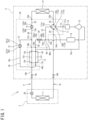
- FIG. 1 is a diagram of a schematic configuration of a refrigeration apparatus to which a refrigerant pipe unit according to a first embodiment of the present disclosure is applied.
- the refrigeration apparatus 1 is, for example, an air conditioner for cooling and heating air in a room.
- the refrigeration apparatus 1 includes an outdoor unit 2 installed outside the room, and an indoor unit 3 installed in the room.
- the outdoor unit 2 and the indoor unit 3 are connected to each other with a refrigerant pipe 10.
- the refrigeration apparatus 1 may include a single indoor unit 3 or may include a plurality of indoor units 3.
- the refrigeration apparatus 1 includes a refrigerant circuit 4 for carrying out a vapor compression refrigeration cycle operation.
- the refrigerant circuit 4 includes an indoor heat exchanger 11, a compressor 12, a supercooler 13, an outdoor heat exchanger 14, an outdoor expansion valve 15, an accumulator 16, a four-way switching valve 17, shutoff valves 18L and 18G, an oil separator 19, an indoor expansion valve 20, and the like which are connected to each other with the refrigerant pipe 10.
- the indoor heat exchanger 11 and the indoor expansion valve 20 are of the indoor unit 3.
- the compressor 12, the supercooler 13, the outdoor heat exchanger 14, the outdoor expansion valve 15, the accumulator 16, the four-way switching valve 17, the shutoff valves 18L and 18G, and the oil separator 19 are of the outdoor unit 2.
- the four-way switching valve 17 is switched to a state indicated by a solid line illustrated in FIG. 1 , and the outdoor heat exchanger 14 functions as a refrigerant condenser (radiator) while the indoor heat exchanger 11 functions as a refrigerant evaporator.
- the gas-state refrigerant discharged from the compressor 12 passes through the oil separator 19 and then flows into the outdoor heat exchanger 14.
- the oil separator 19 separates a refrigerating machine oil contained in the gas-state refrigerant, from the gas-state refrigerant.
- the outdoor heat exchanger 14 condenses the gas-state refrigerant into the liquid-state refrigerant by heat exchange with outside air.
- the liquid-state refrigerant then flows into the supercooler 13 via the outdoor expansion valve 15.
- the supercooler 13 cools the refrigerant condensed by the outdoor heat exchanger 14.
- the refrigerant is decompressed at the indoor expansion valve 20.
- the indoor heat exchanger 11 then evaporates the refrigerant by heat exchange with indoor air.
- the refrigerant then passes through the accumulator 16.
- the refrigerant is then sucked into the compressor 12.
- the accumulator 16 separates the gas-state refrigerant and the liquid-state refrigerant from each other. Only the gas-state refrigerant is sucked into the compressor 12.
- the supercooler 13 includes a main flow path 13e and an auxiliary flow path 13f.
- the main flow path 13e includes a first end communicating with a first port 13a of the supercooler 13.
- the supercooler 13 is connected at the first port 13a to a refrigerant pipe 10a extending from the outdoor heat exchanger 14.
- the main flow path 13e includes a second end communicating with a second port 13b of the supercooler 13.
- the supercooler 13 is connected at the second port 13b to a refrigerant pipe 10b extending to the indoor heat exchanger 11.
- the auxiliary flow path 13f includes a first end communicating with a third port 13c of the supercooler 13.
- the supercooler 13 is connected at the third port 13c to a refrigerant pipe 10c branching off the refrigerant pipe 10a.
- the refrigerant pipe 10c is provided with a supercooling expansion valve 21.
- the auxiliary flow path 13f includes a second end communicating with a fourth port 13d of the supercooler 13.
- the supercooler 13 is connected at the fourth port 13d to a refrigerant pipe 10d extending to the accumulator 16.
- the refrigerant pipe 10d is provided with an open-close valve 22.
- the high-pressure liquid refrigerant flowing from the outdoor heat exchanger 14 to the main flow path 13e exchanges heat with the low-pressure gas-liquid two-phase refrigerant decompressed at the supercooling expansion valve 21 and flowing through the auxiliary flow path 13f.
- the refrigeration apparatus 1 includes a refrigerant pipe unit 30 that includes one or more constituent components and refrigerant flow paths connected to and integrated with the constituent components.
- the refrigerant pipe unit 30 according to the present embodiment includes the outdoor expansion valve 15, four-way switching valve 17, supercooling expansion valve 21, and open-close valve 22 as the constituent components, and some of the refrigerant pipes connected to the constituent components.
- the refrigerant pipe unit 30 includes a first flow path 31, a second flow path 32, a third flow path 33, and a fourth flow path 34.
- the first to fourth flow paths 31 to 34 are connected to the four-way switching valve 17.
- the first flow path 31 includes a first end 31a connected to a first port 17a of the four-way switching valve 17, and a second end 31b connected to a refrigerant pipe extending to the oil separator 19.
- the second flow path 32 includes a first end 32a connected to a second port 17b of the four-way switching valve 17, and a second end 32b connected to a refrigerant pipe extending to the outdoor heat exchanger 14.
- the third flow path 33 includes a first end 33a connected to a third port 17c of the four-way switching valve 17, and a second end 33b connected to a refrigerant pipe extending to the accumulator 16.
- the fourth flow path 34 includes a first end 34a connected to a fourth port 17d of the four-way switching valve 17, and a second end 34b connected to a refrigerant pipe extending to the gas-side shutoff valve 18G.
- the refrigerant pipe unit 30 also includes a fifth flow path 35, a sixth flow path 36, a seventh flow path 37, an eighth flow path 38, a ninth flow path 39, and a tenth flow path 40.
- the fifth to tenth flow paths 35 to 40 are connected to the outdoor expansion valve 15, the supercooling expansion valve 21, and the open-close valve 22.
- the fifth flow path 35 includes a first end 35a connected to a first port 15a of the outdoor expansion valve 15, and a second end 35b connected to a refrigerant pipe extending to the outdoor heat exchanger 14.
- the sixth flow path 36 includes a first end 36a connected to a second port 15b of the outdoor expansion valve 15, and a second end 36b connected to a refrigerant pipe extending to the first port 13a of the supercooler 13.
- the seventh flow path 37 includes a first end 37a connected to a midway portion between two ends of the sixth flow path 36, and a second end 37b connected to a first port 21a of the supercooling expansion valve 21.
- the eighth flow path 38 includes a first end 38a connected to a second port 21b of the supercooling expansion valve 21, and a second end 38b connected to a refrigerant pipe extending to the third port 13c of the supercooler 13.
- the ninth flow path 39 includes a first end 39a connected to a first port 22a of the open-close valve 22, and a second end 39b connected to a refrigerant pipe extending to the fourth port 13d of the supercooler 13.
- the tenth flow path 40 includes a first end 40a connected to a second port 22b of the open-close valve 22, and a second end 40b connected to a midway portion between two ends of the third flow path 33.
- a refrigerant pipe 10e for injection includes a first end connected to the compressor 12, and the refrigerant having an intermediate pressure between a suction pressure and a discharge pressure is introduced into the compressor 12 through the refrigerant pipe 10e.
- the refrigerant pipe 10e includes a second end connected to a midway portion between two ends of the refrigerant pipe connecting the second end 39b of the ninth flow path 39 and the fourth port 13d of the supercooler 13.
- the open-close valve 22 When the open-close valve 22 is closed, the intermediate-pressure refrigerant is supplied to the compressor 12 through the refrigerant pipe 10e.
- FIG. 2 is a perspective view of the refrigerant pipe unit.
- the refrigerant pipe unit 30 includes a unit main body 41 and control valves 15, 17, 21, and 22.
- the unit main body 41 includes a plurality of plates 51 to 54 stacked on top of each other.
- the unit main body 41 has a flow path through which the refrigerant flows and that is defined in the unit main body 41.
- the unit main body 41 includes the first plate 51, the second plate 52, the third plate 53, and the fourth plate 54.
- Each of the first plate 51, the second plate 52, and the fourth plate 54 is a plate member having a rectangular shape, a square shape, or the like.
- the first plate 51, the second plate 52, and the fourth plate 54 are equal in outer dimension to one another.
- Each of the plates 51 to 54 is made of metal such as aluminum, an aluminum alloy, or stainless steel.
- the first plate 51, the second plate 52, and the fourth plate 54 are stacked in this order and joined together by brazing.
- the unit main body 41 therefore includes a brazing portion for joining the plates 51, 52, and 54 together.
- the first plate 51, the second plate 52, and the fourth plate 54 are different in thickness from one another.
- the first plate 51 is thicker than the second to fourth plates 52 to 54.
- the second plate 52 is thicker than the third plate 53 and the fourth plate 54.
- the unit main body 41 includes a plurality of third plates 53.
- Each of the third plates 53 is a plate member having a rectangular shape or a square shape.
- Each of the third plates 53 is smaller in outer dimension than the first plate 51 and is stacked on the first plate 51.
- the unit main body 41 according to the present embodiment includes four third plates 53.
- Each of the third plates 53 is joined to the first plate 51 by welding.
- the unit main body 41 therefore includes a welding portion for joining the first plate 51 and each third plate 53 together.
- welding refers to welding that involves melting of a base material.
- the unit main body 41 is manufactured as follows. First, the first plate 51, second plate 52, and fourth plate 54 of the unit main body 41 are joined together by brazing and integrated into one in a furnace. Next, three valve seats 46 and one valve seat 47 as well as three valve bodies 43 and one valve body 44 (to be described later) for the control valves 15, 21, 22, and 17 are respectively inserted into three accommodation holes 51j and one accommodation hole 51h in the first plate 51, and the accommodation holes 51j and 51h as well as the flow paths 31 to 40 are closed with the third plates 53. Thereafter, the third plates 53 and the first plate 51 are joined together by welding.
- the first, second, and fourth plates 51, 52, and 54 which are less susceptible to a thermal influence, can be brazed collectively and, after the brazing, the control valves 15, 21, 22, and 17, which are susceptible to a thermal influence, can be mounted to the first plate 51; therefore, the manufacturability can be improved.
- a first direction Z may refer to a direction in which the first to fourth plates 51 to 54 are stacked (i.e., a normal direction of each of the first to fourth plates 51 to 54), and a second direction X and a third direction Y each may refer to a direction orthogonal to the first direction Z.
- the refrigerant pipe unit 30 is placed with the first direction Z oriented in a heightwise direction.
- FIG. 3 is an exploded perspective view of the refrigerant pipe unit.
- FIG. 4 is a diagram illustrating an internal structure of the refrigerant pipe unit.
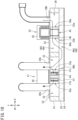
- FIG. 10 is a sectional view of the refrigerant pipe unit, taken along line A-A in FIG. 4 .
- the unit main body 41 includes the first to tenth flow paths 31 to 40 as described above.
- the first plate 51 includes the first to tenth flow paths 31 to 40.
- the first to tenth flow paths 31 to 40 pass through the first plate 51 in the first direction Z.
- Each of the first to tenth flow paths 31 to 40 has a substantially square shape as seen in the first direction Z.
- the first to fourth flow paths 31 to 34 are arranged in the second direction X and the third direction Y on a first side of the first plate 51 in the second direction X (i.e., the right side in FIG. 4 ).
- the first flow path 31 and the second flow path 32 are arranged in the third direction Y and are separated from each other with a first partition wall 51a interposed therebetween.
- the second flow path 32 and the third flow path 33 are arranged in the second direction X and are separated from each other with a second partition wall 51b interposed therebetween.
- the third flow path 33 and the fourth flow path 34 are arranged in the third direction Y and are separated from each other with a third partition wall 51c interposed therebetween.
- the fourth flow path 34 and the first flow path 31 are arranged in the second direction X and are separated from each other with a fourth partition wall 51d interposed therebetween.
- the accommodation hole (accommodation space) 51h is located at an intersection of the first partition wall 51a, the second partition wall 51b, the third partition wall 51c, and the fourth partition wall 51d, and passes through the first plate 51 in the first direction Z.
- the accommodation hole 51h accommodates therein the valve body 44 of the second control valve 17 as will be described later.
- the accommodation hole 51h has a cylindrical inner peripheral surface.
- the fifth to tenth flow paths 35 to 40 are arranged in the second direction X and the third direction Y on a second side of the first plate 51 in the second direction X (i.e., the left side in FIG. 4 ).
- the fifth flow path 35 and the sixth flow path 36 are arranged in the second direction X and are separated from each other with a fifth partition wall 51e interposed therebetween.
- the seventh flow path 37 and the eighth flow path 38 are arranged in the second direction X and are separated from each other with a sixth partition wall 51f interposed therebetween.
- the seventh flow path 37 includes a first portion 37c defined in the first plate 51 and a second portion 37d defined in the second plate 52, as will be described later.
- the ninth flow path 39 and the tenth flow path 40 are arranged in the second direction X and are separated from each other with a seventh partition wall 51g interposed therebetween.
- the tenth flow path 40 includes a first portion 40c defined in the first plate 51 and a second portion 40d defined in the second plate 52, as will be described later.
- the fifth flow path 35, the eighth flow path 38, and the ninth flow path 39 are arranged in this order in the third direction Y
- the sixth flow path 36, the seventh flow path 37, and the tenth flow path 40 are arranged in this order in the third direction Y
- the fifth partition wall 51e, sixth partition wall 51f, and seventh partition wall 51g respectively have the accommodation holes (accommodation spaces) 5 1j each passing through the first plate 51 in the first direction Z.
- the accommodation holes 5 1j respectively accommodate therein the valve bodies 43 of the first control valves 15, 21, and 22 as will be described later.
- the accommodation holes 51j each have a cylindrical inner peripheral surface.
- the seventh flow path 37 is defined in not only the first plate 51, but also the second plate 52.
- the seventh flow path 37 includes the first portion 37c defined in the first plate 51 and the second portion 37d defined in the second plate 52.
- the second portion 37d passes through the second plate 52 in the first direction Z.
- the second portion 37d is an oblong hole formed longitudinally in the third direction Y
- the second portion 37d extends over the sixth flow path 36 and the first portion 37c of the seventh flow path 37 in the first plate 51, so that the sixth flow path 36 and the first portion 37c communicate with each other.
- the tenth flow path 40 is defined in not only the first plate 51, but also the second plate 52.
- the tenth flow path 40 includes the first portion 40c defined in the first plate 51 and the second portion 40d defined in the second plate 52.
- the second portion 40d is an oblong hole formed longitudinally in the second direction X. The second portion 40d extends over the first portion 40c of the tenth flow path 40 and the third flow path 33 in the first plate, so that the first portion 40c and the third flow path 33 communicate with each other.
- the four third plates 53 close the first to tenth flow paths 31 to 40 from above. Specifically, the four third plates 53 respectively close the first to fourth flow paths 31 to 34, fifth and sixth flow paths 35 and 36, seventh and eighth flow paths 37 and 38, and ninth and tenth flow paths 39 and 40.
- the third plates 53 have through holes that define the second ends 31b to 36b of the first to sixth flow paths 31 to 36 as well as the second ends 38b and 39b of the eighth and ninth flow paths 38 and 39 (see FIG. 1 ).
- the refrigerant pipes are respectively connected to the through holes.
- Drivers 45 (to be described later) that constitute the control valves are respectively disposed on the third plates 53.
- the fourth plate 54 is located below the second plate 52.
- the fourth plate 54 has no opening and closes the second portion 37d of the seventh flow path 37 and the second portion 40d of the tenth flow path 40 in the second plate 52 from below.
- the refrigerant pipe unit 30 includes, as the control valves, the outdoor expansion valve 15, supercooling expansion valve 21, open-close valve 22, and four-way switching valve 17 described above with reference to FIG. 1 .
- Each of the outdoor expansion valve 15, the supercooling expansion valve 21, and the open-close valve 22 is a flow rate adjustment valve configured to adjust a flow rate of the refrigerant.
- a first control valve refers to this flow rate adjustment valve.
- the four-way switching valve 17 is a direction switching valve configured to switch a flow direction of the refrigerant.
- a second control valve refers to this direction switching valve.
- Each of the outdoor expansion valve 15 and the supercooling expansion valve 21 adjusts an opening degree of its corresponding valve body between a minimum opening degree and a maximum opening degree continuously or stepwise to adjust the flow rate of the refrigerant.
- the open-close valve 22 switches the opening degree of its valve body to either the maximum opening degree or the minimum opening degree (fully closed), thereby adjusting the flow rate of the refrigerant. In other words, the open-close valve 22 switches between a form of interrupting the flow of the refrigerant and a form of permitting the flow of the refrigerant.
- Each of the outdoor expansion valve 15, the supercooling expansion valve 21, the open-close valve 22, and the four-way switching valve 17 is an electric valve operable by power supply.
- the valves 15, 21, and 22 respectively include the valve bodies 43 and the drivers 45.
- the valve 17 includes the valve body 44 and the driver 45.
- the valve bodies 43 and 44 are disposed in the unit main body 41.
- the drivers 45 are disposed outside the unit main body 41.
- FIG. 5 is an exploded perspective view illustrating a part of the first control valve in the refrigerant pipe unit.
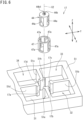
- FIG. 6 is an exploded perspective view illustrating a part of the second control valve in the refrigerant pipe unit.
- FIG. 7 is a sectional view of the first control valve. It should be noted that FIGs. 5 and 7 each illustrate, as an example, the outdoor expansion valve 15 among the plurality of first control valves 15, 21, and 22.
- the outdoor expansion valve 15, supercooling expansion valve 21, and open-close valve 22 are basically equal in structure to each other. In the following, therefore, a description will be given of a specific structure of the outdoor expansion valve 15 as an example.
- the valve body 43 of the outdoor expansion valve 15 has a cylindrical (columnar) shape.
- the valve body 43 has a height in the first direction Z, and this height is substantially equal to a thickness of the first plate 51.
- the valve body 43 has an opening 43a passing through the valve body 43 in a direction parallel to a direction perpendicular to an axial center C1 of the valve body 43.
- the opening 43a crosses the axial center C1 of the valve body 43.
- the opening 43a serves as a passage through which the refrigerant flows.
- the valve body 43 includes a cylindrical projection 43b disposed on an upper surface of the valve body 43 and located on the axial center C1.
- the projection 43b has on its upper surface a groove 43b1 extending in a radial direction of the projection 43b.
- the valve body 43 is accommodated in the accommodation hole (accommodation space) 5 1j bored in the first plate 51.
- the axial center C1 of the valve body 43 extends in parallel with the first direction Z which is the normal direction of the first plate 51.
- the axial center C1 of the valve body 43 is aligned with a center of the accommodation hole 51j.
- the first plate 51 has openings located around the accommodation hole 51j and serving as the first port 15a and second port 15b of the outdoor expansion valve 15.
- the first port 15a allows the accommodation hole 51j and the flow path 35 to communicate with each other.
- the second port 15b allows the accommodation hole 51j and the flow path 36 to communicate with each other.
- the first port 15a and the second port 15b are substantially equal in area to the opening 43a in the valve body 43.
- the first plate 51 is provided with the valve seat 46 that is in contact with the valve body 43.
- the valve seat 46 is made of a synthetic resin and has a cylindrical shape.
- the valve seat 46 has a height in the first direction Z, and this height is substantially equal to the thickness of the first plate 51 in the first direction Z.
- the valve seat 46 has an axial center aligned with the axial center C1 of the valve bodies 43. In the following, therefore, reference sign C1 indicates the axial center of the valve seat 46 in addition to the axial center of the valve body 43.
- the valve seat 46 has an outer diameter that is substantially equal to or slightly smaller than an inner diameter of the accommodation hole 51j.
- the valve seat 46 also has an inner diameter that is substantially equal or slightly larger than an outer diameter of the valve body 43.
- the valve seat 46 is fitted into the accommodation hole 51j and is fixed to the inner peripheral surface of the accommodation hole 51j.
- the valve body 43 is inserted in the valve seat 46 so as to be rotatable about the axial center C1.
- the valve seat 46 has a pair of openings 46a passing through the valve seat 46 in a direction perpendicular to the axial center C1 of the valve seat 46.
- the openings 46a are arranged at positions displaced by 180 degrees in a circumferential direction of the valve seat 46.
- the openings 46a in the valve seat 46 are substantially equal in area to the opening 43a in the valve body 43.
- the valve seat 46 functions as a sealing member that seals a gap between the inner peripheral surface of the accommodation hole 51j and an outer peripheral surface of the valve body 43 to inhibit leakage of the refrigerant through the gap.
- the valve body 44 of the four-way switching valve 17 which is also referred to as the second control valve has a cylindrical (columnar) shape, as in the valve body 43 of the outdoor expansion valve 15.
- the valve body 44 has a height in the first direction Z, and this height is substantially equal to the thickness of the first plate 51.
- the valve body 44 of the four-way switching valve 17 has a pair of openings 44a passing through the valve body 44 in a direction parallel to a direction perpendicular to an axial center C2 of the valve body 44.
- the openings 44a extend in parallel, with the axial center C2 of the valve body 44 interposed therebetween.
- the openings 44a each serve as a passage through which the refrigerant flows.
- the valve body 44 includes a cylindrical projection 44b disposed on an upper surface of the valve body 44 and located on the axial center C2.
- the projection 44b has on its upper surface a groove 44b1 extending in a radial direction of the projection 44b.
- the valve body 44 is accommodated in the accommodation hole (accommodation space) 51h bored in the first plate 51.
- the axial center C2 of the valve body 44 extends in parallel with the first direction Z which is the normal direction of the first plate 51.
- the axial center C2 of the valve body 44 is aligned with a center of the accommodation hole 51h.
- the first plate 51 has openings located around the accommodation hole 51h and serving as the first port 17a, second port 17b, third port 17c, and fourth port 17d of the four-way switching valve 17.
- the first port 17a, second port 17b, third port 17c, and fourth port 17d respectively allow the accommodation hole 51h and the first flow path 31, second flow path 32, third flow path 33, and fourth flow path 34 to communicate with each other.
- the first port 17a, the second port 17b, the third port 17c, and the fourth port 17d are substantially equal in area to the openings 44a in the valve body 44.
- the first plate 51 is provided with the valve seat 47 that is in contact with the valve body 44.
- the valve seat 47 is made of a synthetic resin and has a cylindrical shape.
- the valve seat 47 has a height in the first direction Z, and this height is substantially equal to the thickness of the first plate 51 in the first direction Z.
- the valve seat 47 has an axial center aligned with the axial center C2 of the valve body 44. In the following, therefore, reference sign C2 indicates the axial center of the valve seat 47 in addition to the axial center of the valve body 44.
- the valve seat 47 has an outer diameter that is substantially equal to or slightly smaller than an inner diameter of the accommodation hole 51h.
- the valve seat 47 also has an inner diameter that is substantially equal or slightly larger than an outer diameter of the valve body 44.
- the valve seat 47 is fitted into the accommodation hole 51h and is fixed to the inner peripheral surface of the accommodation hole 51h.
- the valve body 44 is inserted in the valve seat 47 so as to be rotatable about the axial center C1.
- the valve seat 47 has four openings 47a passing through the valve seat 47 in a direction perpendicular to the axial center C2 of the valve seat 47.
- the four openings 47a are spaced away from one another at equal intervals (90-degree intervals) in a circumferential direction of the valve seat 47.
- the openings 47a in the valve seat 47 are substantially equal in area to the openings 44a in the valve body 44.
- the openings 47a in the valve seat 47 are coincide in circumferential position with and communicate with the first port 17a, second port 17b, third port 17c, and fourth port 17d in the first plate 51, respectively.
- the valve seat 47 functions as a sealing member that seals a gap between the inner peripheral surface of the accommodation hole 51h and an outer peripheral surface of the valve body 44 to inhibit leakage of the refrigerant through the gap.
- the driver 45 of the outdoor expansion valve 15 is constituted of an electric motor such as a stepping motor.
- the driver 45 includes a rotor 45a, a stator 45b, and a cover 45c.
- the stator 45b includes a coil 45b1.
- the rotor 45a includes a projection 45a1 disposed on a lower end of the rotor 45a.
- the projection 45a1 of the rotor 45a is inserted in the groove 43b1 in the projection 43b of the valve body 43.
- the projection 45a1 of the rotor 45a and the projection 43b of the valve body 43 thus engage with each other, so that the rotor 45a and the valve body 43 are integrally rotatable about the axial center C1.
- the cover 45c is a plate member made of metal such as aluminum, an aluminum alloy, or stainless steel.
- the cover 45c has a cylindrical shape with its upper end closed, and covers an outer peripheral portion and an upper portion of the rotor 45a.
- the cover 45c is integrated with the third plate 53.
- the stator 45b covers an outer peripheral portion and an upper portion of the cover 45c.
- the cover 45c may alternatively be provided separately from the third plate 53.
- the driver 45 rotates the valve body 43 about the axial center C1 at a desired rotational angle in such a manner that the stator 45b excited by energization to the coil 45b1 rotates the rotor 45a.
- the valve body 43 changes, in accordance with its amount of rotation, a flow rate of the refrigerant flowing through the opening 43a, and accordingly changes a flow of the refrigerant in the flow paths 35 and 36 of the unit main body 41 communicating with the opening 43a.
- the four-way switching valve 17, which is the second control valve, also includes a driver 45 similar in configuration to the driver 45 of the outdoor expansion valve 15.
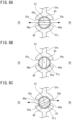
- FIGs. 8A to 8C are diagrams each illustrating action of the first control valve.
- the outdoor expansion valve 15, which is the first control valve, has an opening degree adjusted by a rotation of the valve body 43 to one of a state of a maximum opening degree (fully open) illustrated in FIG. 8A , a state of a minimum opening degree (fully closed) illustrated in FIG. 8B , and a state of an intermediate opening degree illustrated in FIG. 8C . At the intermediate opening degree, the amount of rotation of the valve body 43 is adjusted continuously or stepwise.
- the outdoor expansion valve 15 is capable of adjusting the flow rate of the refrigerant flowing through the flow paths 35 and 36, based on the adjustment to its opening degree.
- the open-close valve 22 has an opening degree adjusted to one of the state of the maximum opening degree illustrated in FIG. 8A and the state of the minimum opening degree illustrated in FIG. 8B .
- the adjustment to the opening degree enables switching between the form of permitting the flow of the refrigerant in the flow paths 35 and 36 and the form of interrupting the flow of the refrigerant in the flow paths 35 and 36.
- FIGs. 9A and 9B are diagrams each illustrating action of the second control valve.
- the four-way switching valve 17, which is the second control valve, switches, by a rotation of the valve body 44, a flow direction of the refrigerant to one of a state in which the first flow path 31 communicates with the second flow path 32 while the third flow path 33 communicates with the fourth flow path 34 as illustrated in FIG. 9A and a state in which the first flow path 31 communicates with the fourth flow path 34 while the second flow path 32 communicates with the third flow path 33 as illustrated in FIG. 9B .
- the switching of the flow direction enables switching between a cooling operation and a heating operation by the air conditioner 1.
- the refrigerant pipe unit 30 includes the plurality of control valves 15, 21, 22, and 17, and the control valves 15, 21, 22, and 17 include the valve bodies 43 and 44 disposed on the first plate 51 in a rotatable manner.
- the valve bodies 43 and 44 respectively have the openings 43a and 44a each serving as a refrigerant passage.
- the valve bodies 43 and 44 change the flow of the refrigerant in the flow paths 31 to 40, in accordance with their amounts of rotation.
- the valve bodies 43 and 44 respectively rotate about the axial centers C1 and C2 extending in parallel with the normal direction Z of the first plate 51.
- the openings 43a and 44a are defined along the direction orthogonal to the axial centers C1 and C2.
- the inlet-side flow paths through which the refrigerant flows into the openings 43a and 44a in the valve bodies 43 and 44 and the outlet-side flow paths through which the refrigerant flows out of the openings 43a and 44a can be arranged linearly, which enables a reduction in space for these flow paths.
- the valve bodies 43 of the first control valves 15, 21, and 22 are respectively accommodated in the accommodation spaces 5 1j in the first plate 51 and are respectively in contact with the valve seats 46 of the first plate 51.
- the valve body 44 of the second control valve 17 is accommodated in the accommodation space 51h in the first plate 51 and is in contact with the valve seat 47 of the first plate 51.
- the first plate 51 therefore functions as a casing for the first control valves 15, 21, and 22 and the second control valve 17. This configuration thus achieves a reduction in size of the refrigerant pipe unit 30.
- the outdoor expansion valve 15, supercooling expansion valve 21, and open-close valve 22 include the valve bodies 43 of the same type and the valve seats 46 of the same type. This configuration therefore achieves a reduction in manufacturing cost by the use of common components.
- control valves of different types can be configured with ease by changing the structures of valve bodies to be accommodated in the accommodation spaces 51h and 51j.
- Any of the accommodation holes 51h and 51j may accommodate therein components different from a valve body, such as a filter.
- FIG. 11 is a perspective view of a refrigerant pipe unit according to a second embodiment of the present disclosure.
- a refrigerant pipe unit 60 includes a unit main body 61 and control valves 62, 63, and 64.
- the unit main body 61 includes a plurality of plates 71 to 75 stacked on top of each other.
- the unit main body 61 has a flow path through which a refrigerant flows and that is defined in the unit main body 61.
- the unit main body 61 includes the first plate 71, the second plate 72, the third plate 73, the fourth plate 74, and the fifth plate 75.
- Each of the first plate 71, the second plate 72, the fourth plate 74, and the fifth plate 75 is a plate member having a rectangular shape, a square shape, or the like.
- the first plate 71, the second plate 72, the fourth plate 74, and the fifth plate 75 are equal in outer dimension to one another.
- the first plate 71, the second plate 72, the fourth plate 74, and the fifth plate 75 are stacked in this order and joined together by brazing.
- the unit main body 61 therefore includes a brazing portion for joining the plates 71, 72, 74, and 75 together.
- the first plate 71 is substantially equal in thickness to the second plate 72.
- the third plate 73, the fourth plate 74, and the fifth plate 75 are different in thickness from the first plate 71 and the second plate 72.
- the fourth plate 74 is thicker than the first plate 71 and the second plate 72.
- the third plate 73 and the fifth plate 75 are thinner than the first plate 71.
- the unit main body 61 includes a plurality of third plates 73.
- the third plates 73 have sizes that respectively cover valve bodies (to be described later) and flow paths (to be described later) through which the refrigerant flows.
- Each of the third plates 73 is smaller in outer dimension than the first plate 71 and is stacked on the first plate 71.
- the unit main body 61 according to the present embodiment includes eleven third plates 73.
- Each of the third plates 73 is joined to the first plate 71 by welding.
- the unit main body 61 therefore includes a welding portion for joining the first plate 71 and each third plate 73 together.
- the first plate 71 has a plurality of holes 65 through which refrigerant pipes are connected to the flow paths in the unit main body 61.
- FIG. 12 is a plan view of a second control valve.
- a second control valve 62 is a direction switching valve.
- the second control valve 62 is a three-way switching valve for adjusting a flow direction of the refrigerant by causing two of three flow paths 67, 98, and 69 defined in the first plate 71 and the like to selectively communicate with each other.
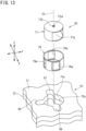
- FIG. 13 is an exploded perspective view of a part of the second control valve.
- FIG. 15 is a sectional view illustrating the second control valve and a refrigerant flow path around the second control valve.
- the first plate 71 has an accommodation hole (first accommodation space) 71a passing through the first plate 71 in the first direction Z.
- the second plate 72 has an accommodation hole (second accommodation space) 72a passing through the second plate 72 in the first direction Z.
- the accommodation holes 71a and 72a each have a cylindrical shape, are equal in inner diameter to each other, and are arranged concentrically.
- the first plate 71 has three flow paths 67, 68, and 69 defined around the accommodation hole 71a.
- the second plate 72 has three flow paths 67, 68, and 69 defined around the accommodation hole 72a.
- the flow path 67 and the flow path 69 are arranged in a circumferential direction of the accommodation holes 71a and 72a so as to face each other at an angle of 180 degrees.
- the flow path 68 is arranged in the circumferential direction of the accommodation holes 71a and 72a at an angle of 90 degrees relative to the flow path 67 and the flow path 69.
- the flow paths 67, 68, and 69 have widths smaller than the diameters of the accommodation holes 71a and 72a as seen in the first direction Z.
- the second control valve 62 includes a valve body 77 and a driver 78.
- the valve body 77 is disposed in the unit main body 61.
- the driver 78 is disposed outside the unit main body 41.
- the driver 78 is equal in configuration to the driver 45 described above with reference to, for example, FIG. 7 ; therefore, the detailed description thereof will not be given here.
- the valve body 77 has a cylindrical (columnar) shape.
- the valve body 77 has a height in the first direction Z, and this height is substantially equal to a sum of a thickness of the first plate 71 and a thickness of the second plate 72.
- the valve body 77 has an opening 77a passing through the valve body 77 in a direction parallel to a direction perpendicular to an axial center C3 of the valve body 77.
- the opening 77a crosses the axial center C3 of the valve body 77.
- the opening 77a serves as a passage through which the refrigerant flows.
- the opening 77a is biased toward a first side in a radial direction, within a range that covers the axial center C3 of the valve body 77.
- the valve body 77 includes a cylindrical projection 77b disposed on an upper surface of the valve body 77 and located on the axial center C3.
- the projection 77b has on its upper surface a groove 77b1 extending in a radial direction of the projection 77b.
- the valve body 77 is accommodated in the accommodation holes (accommodation spaces) 71a and 72a respectively bored in the first and second plates 71 and 72.
- the axial center C3 of the valve body 77 extends in parallel with the first direction Z which is the normal direction of the first plate 71.
- the axial center C3 of the valve body 77 is aligned with centers of the accommodation holes 71a and 72a.
- the first plate 71 and the second plate 72 are provided with a valve seat 79 that is in contact with the valve body 77.
- the valve seat 79 is made of a synthetic resin and has a cylindrical shape.
- the valve seat 79 has a height in the first direction Z, and this height is substantially equal to the sum of the thickness of the first plate 71 and the thickness of the second plate 72 in the first direction Z.
- the valve seat 79 has an axial center aligned with the axial center C3 of the valve body 77. In the following, therefore, reference sign C3 indicates the axial center of the valve seat 79 in addition to the axial center of the valve body 77.
- the valve seat 79 has an outer diameter that is substantially equal to or slightly smaller than the inner diameters of the accommodation holes 71a and 72a.
- the valve seat 79 also has an inner diameter that is substantially equal or slightly larger than an outer diameter of the valve body 77.
- the valve seat 79 is fitted into the accommodation holes 71a and 72a and is fixed to inner peripheral surfaces of the accommodation holes 71a and 72a.
- the valve body 77 is inserted in the valve seat 79 so as to be rotatable about the axial center C3.
- the valve seat 79 has three openings 79a passing through the valve seat 79 in a direction perpendicular to the axial center C3 of the valve seat 79.
- the three openings 79a are spaced away from one another at an angle of 90 degrees in a circumferential direction of the valve seat 79.
- the openings 79a in the valve seat 79 are coincide in circumferential position with and communicate with the flow paths 67, 68, and 69, respectively.
- the valve seat 79 functions as a sealing member that seals a gap between the inner peripheral surfaces of the accommodation holes 71a and 72a and an outer peripheral surface of the valve body 77 to inhibit leakage of the refrigerant through the gap.
- the fourth plate 74 includes flow paths 80 and 81 respectively communicating with the flow paths 67 and 69 in the first plate 71 and second plate 72.
- the fifth plate 75 is located below the fourth plate 74 so as to close the flow paths 80 and 81 from below.
- FIGs. 14A to 14C are diagrams each illustrating action of the second control valve.
- the second control valve 62 switches, in accordance with an amount of rotation of the valve body 77, a flow direction of the refrigerant to one of a state in which the flow path 67 and the flow path 69, which face each other at an angle of 180 degrees, communicate with each other as illustrated in FIG. 14A , a state in which the flow path 68 and the flow path 69, which are spaced away from each other at an angle of 90 degrees, communicate with each other as illustrated in FIG. 14B , and a state in which the flow path 67 and the flow path 68, which are spaced away from each other at an angle of 90 degrees, communicate with each other as illustrated in FIG. 14C .
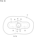
- FIG. 16 is a plan view of a first control valve.
- a first control valve 63 is a flow rate adjustment valve.
- the first control valve 63 changes a flow of the refrigerant at two flow paths 84 and 85 defined in the first plate 71.
- the first control valve 63 includes a valve body 88 and a driver 78.
- the driver 78 is equal in configuration to the driver 45 described above with reference to, for example, FIG. 7 .
- FIG. 17 is an exploded perspective view of a part of the first control valve.
- FIG. 18 is a sectional view illustrating the first control valve and a refrigerant flow path around the first control valve.
- the valve body 88 of the first control valve 63 is equal in configuration to the valve bodies 43 of the first control valves 15, 21, and 22 described above with reference to, for example, FIG. 5 .
- the valve body 88 of the first control valve 63 changes a flow of the refrigerant in the manner described above with reference to FIGs. 8A to 8C .
- the valve body 88 has a cylindrical shape and has an opening 88a passing through the valve body 88 in a direction perpendicular to an axial center C4 of the valve body 88.
- the valve body 88 has a height in the first direction Z, and this height is substantially equal to the sum of the thickness of the first plate 71 and the thickness of the second plate 72.
- the valve body 88 is accommodated in an accommodation hole (first accommodation space) 71b bored in the first plate 71 and an accommodation hole (second accommodation space) 72b bored in the second plate 72 so as to extend over the accommodation hole 71b and the accommodation hole 72b.
- the axial center C4 of the valve body 88 extends in parallel with the first direction Z which is the normal direction of the first plate 71.
- the axial center C4 of the valve body 88 is aligned with centers of the accommodation holes 71b and 72b.
- the first plate 71 and the second plate 72 are provided with a valve seat 89 that is in contact with the valve body 77.
- the valve seat 89 is equal in configuration to the valve seats 46 of the first control valves 15, 21, and 22 described above with reference to, for example, FIG. 5 .
- the valve seat 89 has a cylindrical shape and has a pair of openings 89a passing through the valve seat 89 in a direction perpendicular to an axial center C4 of the valve seat 89.
- the valve seat 89 is fitted into and fixed to the two accommodation holes 71b and 72b in each of the first plate 71 and the second plate 72.
- the first plate 71 and the second plate 72 each have the flow paths 84 and 85 respectively communicating with the accommodation holes 71b and 72b.
- the fourth plate 72 has flow paths 86 and 87 communicating with the flow paths 84 and 85.
- the first control valve 63 is configured to adjust a flow rate of the refrigerant flowing through the flow paths 84, 85, 86, and 87.
- FIG. 19 is an exploded perspective view of a part of a first control valve according to another example.
- FIG. 20 is a sectional view illustrating the first control valve according to the another example and a refrigerant flow path around the first control valve.
- the first control valve 64 is a flow rate control valve, which is similar to the first control valve 63.
- the first control valve 64 includes a valve body 91 and a driver 78.
- the driver 78 is equal in configuration to the driver 45 described above with reference to, for example, FIG. 7 .
- the valve body 91 of the first control valve 64 is equal in configuration to the valve bodies 43 of the first control valves 15, 21, and 22 described above with reference to, for example, FIG. 5 .
- the valve body 91 of the first control valve 64 changes a flow of the refrigerant in the manner described above with reference to FIGs. 8A to 8C .
- the valve body 91 has a cylindrical shape and has an opening 91a passing through the valve body 91 in a direction perpendicular to an axial center C4 of the valve body 91.
- the valve body 91 has a height in the first direction Z, and this height is substantially equal to a thickness of a first plate 71 in the first direction Z. Therefore, the height of the valve body 91 is lower than the height of the valve body 88 of the first control valve 63 illustrated in FIG. 17 .
- the valve body 91 is accommodated in an accommodation hole (first accommodation space) 71c bored in the first plate 71.
- the axial center C5 of the valve body 91 extends in parallel with the first direction Z which is the normal direction of the first plate 71.
- the axial center C5 of the valve body 91 is aligned with a center of the accommodation hole 71c.
- the first plate 71 is provided with a valve seat 92 that is in contact with the valve body 91.
- the valve seat 92 is equal in configuration to the valve seats 46 of the first control valves 15, 21, and 22 described above with reference to, for example, FIG. 5 .
- the valve seat 92 has a pair of openings 92a.
- the valve seat 89 is fitted into and fixed to the accommodation hole 71c bored in the first plate 71.
- the first plate 71 has flow paths 94 and 95 communicating with the accommodation hole 71c.
- the second plate 72 has flow paths 96 and 97 communicating with the flow paths 94 and 95.
- the first control valve 64 is configured to adjust a flow rate of the refrigerant flowing through the flow paths 94, 95, 96, and 97.
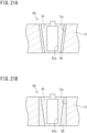
- FIGs. 21A and 21B are sectional views respectively illustrating modifications of the first control valve according to the second embodiment.
- a first control valve 64 includes a valve body 91 having a conical shape, more specifically a truncated cone shape.
- a first plate 71 has an accommodation hole 71c having a truncated cone shape.
- a valve seat 92 fitted in the accommodation hole 71c also has a truncated cone shape.
- a valve body 91 has a conical shape, more specifically a truncated cone shape.
- an accommodation hole 71c has a cylindrical shape.
- a valve seat 92 fitted into an accommodation hole 71c has a cylindrical outer peripheral surface and a conical (truncated cone-shaped) inner peripheral surface.
- valve body 91 is externally inserted into the accommodation hole 71c in the first plate 71 with ease. Therefore, the refrigerant pipe unit 60 is manufactured with ease.
- the conical valve body is also applicable to each of the control valves 15, 21, 22, and 17 described above in the first embodiment and each of the control valves 62 and 63 described above in the second embodiment.
- the accommodation space accommodating the valve body is not limited to the accommodation hole passing through one of or both the first plate and the second plate.
- the accommodation space accommodating the valve body may alternatively be an accommodation recess to be formed by recessing the surface of one of the first plate and the second plate or recessing surfaces of both the first plate and the second plate.
- the refrigerant passage in the valve body is not limited to the hole passing through the valve body.
- the refrigerant passage may alternatively be a recessed groove to be formed in the outer peripheral surface of the valve body.
- the valve body of the control valve may be accommodated in only the second plate.
- the valve body may be disposed in the refrigerant pipe unit with the axial center oriented toward a direction crossing the first direction.
- the valve seat is configured with the sealing member provided separately from one of or both the first plate and the second plate.
- the sealing member is omittable.
- the valve body is brought into direct contact with the inner peripheral surface of the accommodation hole in one of the first plate and the second plate or the inner peripheral surfaces of the accommodation holes in both the first plate and the second plate. The inner peripheral portion of the accommodation hole can thus be used as the valve seat.
- the hole, through which the another refrigerant pipe is connected to the flow path in the unit main body, is bored in the upper surface of the unit main body (i.e., the upper surface of the first or third plate).
- the hole may alternatively be bored in a lower surface or a side surface of the unit main body.
- the valve body may have, for example, a spherical shape in addition to the cylindrical shape or the conical shape.
- the control valve may include a casing accommodating the valve body and including a valve seat that is in contact with the valve body.
- the control valve may be disposed together with the casing in one of or both the first plate and the second plate.
Landscapes
- Engineering & Computer Science (AREA)
- General Engineering & Computer Science (AREA)
- Mechanical Engineering (AREA)
- Physics & Mathematics (AREA)
- Thermal Sciences (AREA)
- Fluid Mechanics (AREA)
- Multiple-Way Valves (AREA)
- Sliding Valves (AREA)
Abstract
Description
- The present disclosure relates to a refrigerant pipe unit and a refrigeration apparatus.
- In a known refrigeration apparatus including a refrigerant circuit for carrying out a vapor compression refrigeration cycle operation, refrigerant pipes through which a refrigerant flows have been integrated into one unit in order to reduce the size of the refrigerant circuit. For example,
Patent Literature 1 discloses a refrigerant pipe unit including three plates that are stacked on top of each other. In this refrigerant pipe unit, a refrigerant flow path is defined between two of the stacked plates, and a valve body, such as an expansion valve or an electromagnetic valve, for controlling the flow of the refrigerant is inserted in one of the plates. - PATENT LITERATURE 1:
Japanese Laid-Open Patent Publication No. 2009-41812 - According to the refrigerant pipe unit disclosed in
Patent Literature 1, the valve body is inserted in one of the plates and is configured to move, by linear motion, between a position to narrow the refrigerant flow path and a position to open the refrigerant flow path; therefore, this plate requires a space for allowing the valve body to move linearly. Consequently, the refrigerant pipe unit disclosed inPatent Literature 1 is less likely to achieve a size reduction in a direction in which the valve body moves. - An object of the present disclosure is to provide a compact refrigerant pipe unit and a refrigeration apparatus including the same.
-
- (1) A refrigerant pipe unit according to the present disclosure includes
- a first plate,
- a second plate stacked on the first plate, and
- a control valve.
- One of or both the first plate and the second plate includes or include a refrigerant flow path.
- The control valve includes
- a valve body including a refrigerant passage communicating with the refrigerant flow path, the valve body rotatably disposed in the first plate, the valve body configured to change a flow of a refrigerant at the refrigerant flow path, in accordance with an amount of rotation, and
- a driver configured to adjust the amount of rotation of the valve body.
- As used herein, the term "to change a flow of a refrigerant" refers to, for example, adjusting a flow rate of the refrigerant or switching a flow direction of the refrigerant.
- In the refrigerant pipe unit having the configuration described above, the valve body of the control valve includes the refrigerant passage, and the flow of the refrigerant at the refrigerant flow path changes by a rotation of the valve body. This configuration therefore eliminates or considerably reduces a movement of the valve body in changing the flow of the refrigerant (e.g., a linear movement in a radial direction or along an axial center of rotation of the valve body). As a result, the first plate has almost no necessity to ensure a space that allows the movement of the valve body. This configuration thus achieves a reduction in size of the refrigerant pipe unit.
- (2) Preferably, the refrigerant passage extends in a direction perpendicular to an axial center of rotation of the valve body.
- (3) Preferably, the valve body has an axial center of rotation extending in parallel with a normal direction of the first plate.
- According to this configuration, for example, an inlet-side refrigerant flow path through which the refrigerant flows into the refrigerant passage in the valve body and an outlet-side refrigerant flow path through which the refrigerant flows out of the refrigerant passage in the valve body can be arranged in a linear or planar form in a direction crossing the axial center of rotation of the valve body. This configuration thus achieves a reduction in size of the refrigerant pipe unit in the normal direction of the first plate.
- (4) Preferably, the first plate includes a first accommodation space communicating with the refrigerant flow path.
- The valve body is accommodated in the first accommodation space.
- The first plate is provided with a first valve seat that is in contact with the valve body in the first accommodation space.
- According to this configuration, the valve body is directly disposed in the first plate. Therefore, the control valve can be constituted of the valve seat disposed in the first plate, the valve body, and the driver. This configuration also achieves a reduction in size of the refrigerant pipe unit.
- (5) Preferably, the valve body has a cylindrical shape or a conical shape.
- According to this configuration, the valve body is easily accommodated in the accommodation space from the outside of the first plate. It should be noted that the term "conical shape" involves a truncated cone shape corresponding to a conical shape from which a leading end is cut.
- (6) Preferably, the first valve seat includes a sealing member disposed in the first plate.
- This configuration ensures hermeticity between the valve body and the first valve seat corresponding to the sealing member and therefore inhibits leakage of the refrigerant.
- (7) Preferably, the second plate includes a second accommodation space communicating with the refrigerant flow path.
- The valve body is accommodated in the first accommodation space and the second accommodation space so as to extend over the first accommodation space and the second accommodation space.
- The second plate is provided with a second valve seat that is in contact with the valve body in the second accommodation space.
- (8) Preferably, the refrigerant pipe unit further includes
- a third plate stacked on the first plate, the third plate disposed opposite the second plate across the first plate in a normal direction of the first plate, the third plate covering the valve body,
- a brazing portion joining the first plate and the second plate together, and
- a welding portion joining the first plate and the third plate together.
- (9) Preferably, the refrigerant pipe unit further includes
- a first control valve configured to adjust a flow rate of the refrigerant in accordance with the amount of rotation of the valve body, and
- a second control valve configured to switch a flow direction of the refrigerant in accordance with the amount of rotation of the valve body.
- This configuration allows the refrigerant pipe unit to have a function of controlling multiple flows of the refrigerant.
-
-
FIG. 1 is a diagram of a schematic configuration of a refrigeration apparatus to which a refrigerant pipe unit according to a first embodiment of the present disclosure is applied. -
FIG. 2 is a perspective view of the refrigerant pipe unit. -
FIG. 3 is an exploded perspective view of the refrigerant pipe unit. -
FIG. 4 is a diagram illustrating an internal structure of the refrigerant pipe unit. -
FIG. 5 is an exploded perspective view illustrating a part of a first control valve in the refrigerant pipe unit. -
FIG. 6 is an exploded perspective view illustrating a part of a second control valve in the refrigerant pipe unit. -
FIG. 7 is a sectional view of the first control valve. -
FIGs. 8A to 8C are diagrams each illustrating action of the first control valve. -
FIGs. 9A and 9B are diagrams each illustrating action of the second control valve. -
FIG. 10 is a sectional view of the refrigerant pipe unit, taken along line A-A inFIG. 4 . -
FIG. 11 is a perspective view of a refrigerant pipe unit according to a second embodiment of the present disclosure. -
FIG. 12 is a plan view of a second control valve. -
FIG. 13 is an exploded perspective view of a part of the second control valve. -
FIGs. 14A to 14C are diagrams each illustrating action of the second control valve. -
FIG. 15 is a sectional view illustrating the second control valve and a refrigerant flow path around the second control valve. -
FIG. 16 is a plan view of a first control valve. -
FIG. 17 is an exploded perspective view of a part of the first control valve. -
FIG. 18 is a sectional view illustrating the first control valve and a refrigerant flow path around the first control valve. -
FIG. 19 is an exploded perspective view of a part of a first control valve according to another example. -
FIG. 20 is a sectional view illustrating the first control valve according to the another example and a refrigerant flow path around the first control valve. -
FIGs. 21A and 21B are sectional views respectively illustrating modifications of the first control valve according to the second embodiment. - Hereinafter, embodiments of the present disclosure will be described in detail with reference to the accompanying drawings.
-
FIG. 1 is a diagram of a schematic configuration of a refrigeration apparatus to which a refrigerant pipe unit according to a first embodiment of the present disclosure is applied. - The
refrigeration apparatus 1 is, for example, an air conditioner for cooling and heating air in a room. Therefrigeration apparatus 1 includes an outdoor unit 2 installed outside the room, and an indoor unit 3 installed in the room. The outdoor unit 2 and the indoor unit 3 are connected to each other with arefrigerant pipe 10. Therefrigeration apparatus 1 may include a single indoor unit 3 or may include a plurality of indoor units 3. - The
refrigeration apparatus 1 includes a refrigerant circuit 4 for carrying out a vapor compression refrigeration cycle operation. The refrigerant circuit 4 includes an indoor heat exchanger 11, acompressor 12, asupercooler 13, anoutdoor heat exchanger 14, anoutdoor expansion valve 15, anaccumulator 16, a four-way switching valve 17,shutoff valves oil separator 19, anindoor expansion valve 20, and the like which are connected to each other with therefrigerant pipe 10. - Among the constituent components of the refrigerant circuit 4, the indoor heat exchanger 11 and the
indoor expansion valve 20 are of the indoor unit 3. Among the constituent components of the refrigerant circuit 4, thecompressor 12, thesupercooler 13, theoutdoor heat exchanger 14, theoutdoor expansion valve 15, theaccumulator 16, the four-way switching valve 17, theshutoff valves oil separator 19 are of the outdoor unit 2. - During a cooling operation carried out by the
air conditioner 1, the four-way switching valve 17 is switched to a state indicated by a solid line illustrated inFIG. 1 , and theoutdoor heat exchanger 14 functions as a refrigerant condenser (radiator) while the indoor heat exchanger 11 functions as a refrigerant evaporator. The gas-state refrigerant discharged from thecompressor 12 passes through theoil separator 19 and then flows into theoutdoor heat exchanger 14. Theoil separator 19 separates a refrigerating machine oil contained in the gas-state refrigerant, from the gas-state refrigerant. Theoutdoor heat exchanger 14 condenses the gas-state refrigerant into the liquid-state refrigerant by heat exchange with outside air. The liquid-state refrigerant then flows into thesupercooler 13 via theoutdoor expansion valve 15. Thesupercooler 13 cools the refrigerant condensed by theoutdoor heat exchanger 14. After passing through thesupercooler 13, the refrigerant is decompressed at theindoor expansion valve 20. The indoor heat exchanger 11 then evaporates the refrigerant by heat exchange with indoor air. The refrigerant then passes through theaccumulator 16. The refrigerant is then sucked into thecompressor 12. Theaccumulator 16 separates the gas-state refrigerant and the liquid-state refrigerant from each other. Only the gas-state refrigerant is sucked into thecompressor 12. - The
supercooler 13 includes amain flow path 13e and anauxiliary flow path 13f. Themain flow path 13e includes a first end communicating with afirst port 13a of thesupercooler 13. Thesupercooler 13 is connected at thefirst port 13a to arefrigerant pipe 10a extending from theoutdoor heat exchanger 14. Themain flow path 13e includes a second end communicating with asecond port 13b of thesupercooler 13. Thesupercooler 13 is connected at thesecond port 13b to arefrigerant pipe 10b extending to the indoor heat exchanger 11. - The
auxiliary flow path 13f includes a first end communicating with athird port 13c of thesupercooler 13. Thesupercooler 13 is connected at thethird port 13c to arefrigerant pipe 10c branching off therefrigerant pipe 10a. Therefrigerant pipe 10c is provided with asupercooling expansion valve 21. Theauxiliary flow path 13f includes a second end communicating with afourth port 13d of thesupercooler 13. Thesupercooler 13 is connected at thefourth port 13d to arefrigerant pipe 10d extending to theaccumulator 16. Therefrigerant pipe 10d is provided with an open-close valve 22. In thesupercooler 13, the high-pressure liquid refrigerant flowing from theoutdoor heat exchanger 14 to themain flow path 13e exchanges heat with the low-pressure gas-liquid two-phase refrigerant decompressed at thesupercooling expansion valve 21 and flowing through theauxiliary flow path 13f. - The
refrigeration apparatus 1 according to the present disclosure includes arefrigerant pipe unit 30 that includes one or more constituent components and refrigerant flow paths connected to and integrated with the constituent components. Therefrigerant pipe unit 30 according to the present embodiment includes theoutdoor expansion valve 15, four-way switching valve 17, supercoolingexpansion valve 21, and open-close valve 22 as the constituent components, and some of the refrigerant pipes connected to the constituent components. - Specifically, the
refrigerant pipe unit 30 includes afirst flow path 31, asecond flow path 32, athird flow path 33, and afourth flow path 34. The first tofourth flow paths 31 to 34 are connected to the four-way switching valve 17. Thefirst flow path 31 includes afirst end 31a connected to afirst port 17a of the four-way switching valve 17, and asecond end 31b connected to a refrigerant pipe extending to theoil separator 19. Thesecond flow path 32 includes afirst end 32a connected to asecond port 17b of the four-way switching valve 17, and asecond end 32b connected to a refrigerant pipe extending to theoutdoor heat exchanger 14. - The
third flow path 33 includes afirst end 33a connected to athird port 17c of the four-way switching valve 17, and asecond end 33b connected to a refrigerant pipe extending to theaccumulator 16. Thefourth flow path 34 includes afirst end 34a connected to afourth port 17d of the four-way switching valve 17, and asecond end 34b connected to a refrigerant pipe extending to the gas-side shutoff valve 18G. - The
refrigerant pipe unit 30 also includes afifth flow path 35, asixth flow path 36, aseventh flow path 37, aneighth flow path 38, aninth flow path 39, and atenth flow path 40. The fifth totenth flow paths 35 to 40 are connected to theoutdoor expansion valve 15, the supercoolingexpansion valve 21, and the open-close valve 22. Thefifth flow path 35 includes afirst end 35a connected to afirst port 15a of theoutdoor expansion valve 15, and asecond end 35b connected to a refrigerant pipe extending to theoutdoor heat exchanger 14. Thesixth flow path 36 includes afirst end 36a connected to asecond port 15b of theoutdoor expansion valve 15, and asecond end 36b connected to a refrigerant pipe extending to thefirst port 13a of thesupercooler 13. - The
seventh flow path 37 includes afirst end 37a connected to a midway portion between two ends of thesixth flow path 36, and asecond end 37b connected to afirst port 21a of thesupercooling expansion valve 21. Theeighth flow path 38 includes afirst end 38a connected to asecond port 21b of thesupercooling expansion valve 21, and asecond end 38b connected to a refrigerant pipe extending to thethird port 13c of thesupercooler 13. - The
ninth flow path 39 includes afirst end 39a connected to afirst port 22a of the open-close valve 22, and asecond end 39b connected to a refrigerant pipe extending to thefourth port 13d of thesupercooler 13. Thetenth flow path 40 includes afirst end 40a connected to asecond port 22b of the open-close valve 22, and asecond end 40b connected to a midway portion between two ends of thethird flow path 33. Arefrigerant pipe 10e for injection includes a first end connected to thecompressor 12, and the refrigerant having an intermediate pressure between a suction pressure and a discharge pressure is introduced into thecompressor 12 through therefrigerant pipe 10e. Therefrigerant pipe 10e includes a second end connected to a midway portion between two ends of the refrigerant pipe connecting thesecond end 39b of theninth flow path 39 and thefourth port 13d of thesupercooler 13. When the open-close valve 22 is closed, the intermediate-pressure refrigerant is supplied to thecompressor 12 through therefrigerant pipe 10e. - Next, a description will be given of a specific structure of the
refrigerant pipe unit 30.FIG. 2 is a perspective view of the refrigerant pipe unit. - The
refrigerant pipe unit 30 includes a unitmain body 41 andcontrol valves main body 41 includes a plurality ofplates 51 to 54 stacked on top of each other. The unitmain body 41 has a flow path through which the refrigerant flows and that is defined in the unitmain body 41. - The unit
main body 41 includes thefirst plate 51, thesecond plate 52, thethird plate 53, and thefourth plate 54. Each of thefirst plate 51, thesecond plate 52, and thefourth plate 54 is a plate member having a rectangular shape, a square shape, or the like. Thefirst plate 51, thesecond plate 52, and thefourth plate 54 are equal in outer dimension to one another. Each of theplates 51 to 54 is made of metal such as aluminum, an aluminum alloy, or stainless steel. Thefirst plate 51, thesecond plate 52, and thefourth plate 54 are stacked in this order and joined together by brazing. The unitmain body 41 therefore includes a brazing portion for joining theplates - The
first plate 51, thesecond plate 52, and thefourth plate 54 are different in thickness from one another. Thefirst plate 51 is thicker than the second tofourth plates 52 to 54. Thesecond plate 52 is thicker than thethird plate 53 and thefourth plate 54. - The unit
main body 41 includes a plurality ofthird plates 53. Each of thethird plates 53 is a plate member having a rectangular shape or a square shape. Each of thethird plates 53 is smaller in outer dimension than thefirst plate 51 and is stacked on thefirst plate 51. The unitmain body 41 according to the present embodiment includes fourthird plates 53. Each of thethird plates 53 is joined to thefirst plate 51 by welding. The unitmain body 41 therefore includes a welding portion for joining thefirst plate 51 and eachthird plate 53 together. In the present embodiment, the term "welding" refers to welding that involves melting of a base material. - The unit
main body 41 is manufactured as follows. First, thefirst plate 51,second plate 52, andfourth plate 54 of the unitmain body 41 are joined together by brazing and integrated into one in a furnace. Next, threevalve seats 46 and onevalve seat 47 as well as threevalve bodies 43 and one valve body 44 (to be described later) for thecontrol valves accommodation holes 51j and oneaccommodation hole 51h in thefirst plate 51, and theaccommodation holes flow paths 31 to 40 are closed with thethird plates 53. Thereafter, thethird plates 53 and thefirst plate 51 are joined together by welding. By this manufacturing method, the first, second, andfourth plates control valves first plate 51; therefore, the manufacturability can be improved. - In the following description, a first direction Z may refer to a direction in which the first to
fourth plates 51 to 54 are stacked (i.e., a normal direction of each of the first tofourth plates 51 to 54), and a second direction X and a third direction Y each may refer to a direction orthogonal to the first direction Z. In the present embodiment, therefrigerant pipe unit 30 is placed with the first direction Z oriented in a heightwise direction. -
FIG. 3 is an exploded perspective view of the refrigerant pipe unit.FIG. 4 is a diagram illustrating an internal structure of the refrigerant pipe unit.FIG. 10 is a sectional view of the refrigerant pipe unit, taken along line A-A inFIG. 4 . - The unit
main body 41 includes the first totenth flow paths 31 to 40 as described above. Specifically, thefirst plate 51 includes the first totenth flow paths 31 to 40. The first totenth flow paths 31 to 40 pass through thefirst plate 51 in the first direction Z. Each of the first totenth flow paths 31 to 40 has a substantially square shape as seen in the first direction Z. - The first to
fourth flow paths 31 to 34 are arranged in the second direction X and the third direction Y on a first side of thefirst plate 51 in the second direction X (i.e., the right side inFIG. 4 ). Thefirst flow path 31 and thesecond flow path 32 are arranged in the third direction Y and are separated from each other with afirst partition wall 51a interposed therebetween. Thesecond flow path 32 and thethird flow path 33 are arranged in the second direction X and are separated from each other with asecond partition wall 51b interposed therebetween. Thethird flow path 33 and thefourth flow path 34 are arranged in the third direction Y and are separated from each other with athird partition wall 51c interposed therebetween. Thefourth flow path 34 and thefirst flow path 31 are arranged in the second direction X and are separated from each other with afourth partition wall 51d interposed therebetween. - The accommodation hole (accommodation space) 51h is located at an intersection of the
first partition wall 51a, thesecond partition wall 51b, thethird partition wall 51c, and thefourth partition wall 51d, and passes through thefirst plate 51 in the first direction Z. Theaccommodation hole 51h accommodates therein thevalve body 44 of thesecond control valve 17 as will be described later. Theaccommodation hole 51h has a cylindrical inner peripheral surface. - The fifth to
tenth flow paths 35 to 40 are arranged in the second direction X and the third direction Y on a second side of thefirst plate 51 in the second direction X (i.e., the left side inFIG. 4 ). Thefifth flow path 35 and thesixth flow path 36 are arranged in the second direction X and are separated from each other with afifth partition wall 51e interposed therebetween. Theseventh flow path 37 and theeighth flow path 38 are arranged in the second direction X and are separated from each other with asixth partition wall 51f interposed therebetween. Theseventh flow path 37 includes afirst portion 37c defined in thefirst plate 51 and asecond portion 37d defined in thesecond plate 52, as will be described later. - The
ninth flow path 39 and thetenth flow path 40 are arranged in the second direction X and are separated from each other with aseventh partition wall 51g interposed therebetween. Thetenth flow path 40 includes afirst portion 40c defined in thefirst plate 51 and asecond portion 40d defined in thesecond plate 52, as will be described later. Thefifth flow path 35, theeighth flow path 38, and theninth flow path 39 are arranged in this order in the third direction Y Thesixth flow path 36, theseventh flow path 37, and thetenth flow path 40 are arranged in this order in the third direction Y - The
fifth partition wall 51e,sixth partition wall 51f, andseventh partition wall 51g respectively have the accommodation holes (accommodation spaces) 5 1j each passing through thefirst plate 51 in the first direction Z. The accommodation holes 5 1j respectively accommodate therein thevalve bodies 43 of thefirst control valves accommodation holes 51j each have a cylindrical inner peripheral surface. - As illustrated in
FIG. 3 , theseventh flow path 37 is defined in not only thefirst plate 51, but also thesecond plate 52. As described above, theseventh flow path 37 includes thefirst portion 37c defined in thefirst plate 51 and thesecond portion 37d defined in thesecond plate 52. Thesecond portion 37d passes through thesecond plate 52 in the first direction Z. Thesecond portion 37d is an oblong hole formed longitudinally in the third direction Y Thesecond portion 37d extends over thesixth flow path 36 and thefirst portion 37c of theseventh flow path 37 in thefirst plate 51, so that thesixth flow path 36 and thefirst portion 37c communicate with each other. - As illustrated in
FIGs. 3 and10 , thetenth flow path 40 is defined in not only thefirst plate 51, but also thesecond plate 52. As described above, thetenth flow path 40 includes thefirst portion 40c defined in thefirst plate 51 and thesecond portion 40d defined in thesecond plate 52. Thesecond portion 40d is an oblong hole formed longitudinally in the second direction X. Thesecond portion 40d extends over thefirst portion 40c of thetenth flow path 40 and thethird flow path 33 in the first plate, so that thefirst portion 40c and thethird flow path 33 communicate with each other. - As illustrated in
FIGs. 2 ,3 , and10 , the fourthird plates 53 close the first totenth flow paths 31 to 40 from above. Specifically, the fourthird plates 53 respectively close the first tofourth flow paths 31 to 34, fifth andsixth flow paths eighth flow paths tenth flow paths - As illustrated in
FIG. 2 , thethird plates 53 have through holes that define the second ends 31b to 36b of the first tosixth flow paths 31 to 36 as well as the second ends 38b and 39b of the eighth andninth flow paths 38 and 39 (seeFIG. 1 ). The refrigerant pipes are respectively connected to the through holes. Drivers 45 (to be described later) that constitute the control valves are respectively disposed on thethird plates 53. - As illustrated in
FIG. 3 , thefourth plate 54 is located below thesecond plate 52. Thefourth plate 54 has no opening and closes thesecond portion 37d of theseventh flow path 37 and thesecond portion 40d of thetenth flow path 40 in thesecond plate 52 from below. - As illustrated in
FIGs. 2 and3 , thecontrol valves main body 41. Therefrigerant pipe unit 30 according to the present embodiment includes, as the control valves, theoutdoor expansion valve 15, supercoolingexpansion valve 21, open-close valve 22, and four-way switching valve 17 described above with reference toFIG. 1 . Each of theoutdoor expansion valve 15, the supercoolingexpansion valve 21, and the open-close valve 22 is a flow rate adjustment valve configured to adjust a flow rate of the refrigerant. In the following description, a first control valve refers to this flow rate adjustment valve. The four-way switching valve 17 is a direction switching valve configured to switch a flow direction of the refrigerant. In the following description, a second control valve refers to this direction switching valve. - Each of the
outdoor expansion valve 15 and thesupercooling expansion valve 21 adjusts an opening degree of its corresponding valve body between a minimum opening degree and a maximum opening degree continuously or stepwise to adjust the flow rate of the refrigerant. The open-close valve 22 switches the opening degree of its valve body to either the maximum opening degree or the minimum opening degree (fully closed), thereby adjusting the flow rate of the refrigerant. In other words, the open-close valve 22 switches between a form of interrupting the flow of the refrigerant and a form of permitting the flow of the refrigerant. - Each of the
outdoor expansion valve 15, the supercoolingexpansion valve 21, the open-close valve 22, and the four-way switching valve 17 is an electric valve operable by power supply. Thevalves valve bodies 43 and thedrivers 45. Thevalve 17 includes thevalve body 44 and thedriver 45. Thevalve bodies main body 41. Thedrivers 45 are disposed outside the unitmain body 41. -
FIG. 5 is an exploded perspective view illustrating a part of the first control valve in the refrigerant pipe unit.FIG. 6 is an exploded perspective view illustrating a part of the second control valve in the refrigerant pipe unit.FIG. 7 is a sectional view of the first control valve. It should be noted thatFIGs. 5 and7 each illustrate, as an example, theoutdoor expansion valve 15 among the plurality offirst control valves outdoor expansion valve 15, supercoolingexpansion valve 21, and open-close valve 22 are basically equal in structure to each other. In the following, therefore, a description will be given of a specific structure of theoutdoor expansion valve 15 as an example. - As illustrated in
FIG. 5 , thevalve body 43 of theoutdoor expansion valve 15 has a cylindrical (columnar) shape. Thevalve body 43 has a height in the first direction Z, and this height is substantially equal to a thickness of thefirst plate 51. Thevalve body 43 has anopening 43a passing through thevalve body 43 in a direction parallel to a direction perpendicular to an axial center C1 of thevalve body 43. Theopening 43a crosses the axial center C1 of thevalve body 43. Theopening 43a serves as a passage through which the refrigerant flows. Thevalve body 43 includes acylindrical projection 43b disposed on an upper surface of thevalve body 43 and located on the axial center C1. Theprojection 43b has on its upper surface a groove 43b1 extending in a radial direction of theprojection 43b. - The
valve body 43 is accommodated in the accommodation hole (accommodation space) 5 1j bored in thefirst plate 51. The axial center C1 of thevalve body 43 extends in parallel with the first direction Z which is the normal direction of thefirst plate 51. The axial center C1 of thevalve body 43 is aligned with a center of theaccommodation hole 51j. - The
first plate 51 has openings located around theaccommodation hole 51j and serving as thefirst port 15a andsecond port 15b of theoutdoor expansion valve 15. Thefirst port 15a allows theaccommodation hole 51j and theflow path 35 to communicate with each other. Thesecond port 15b allows theaccommodation hole 51j and theflow path 36 to communicate with each other. Thefirst port 15a and thesecond port 15b are substantially equal in area to theopening 43a in thevalve body 43. - The
first plate 51 is provided with thevalve seat 46 that is in contact with thevalve body 43. Thevalve seat 46 is made of a synthetic resin and has a cylindrical shape. Thevalve seat 46 has a height in the first direction Z, and this height is substantially equal to the thickness of thefirst plate 51 in the first direction Z. Thevalve seat 46 has an axial center aligned with the axial center C1 of thevalve bodies 43. In the following, therefore, reference sign C1 indicates the axial center of thevalve seat 46 in addition to the axial center of thevalve body 43. - The
valve seat 46 has an outer diameter that is substantially equal to or slightly smaller than an inner diameter of theaccommodation hole 51j. Thevalve seat 46 also has an inner diameter that is substantially equal or slightly larger than an outer diameter of thevalve body 43. Thevalve seat 46 is fitted into theaccommodation hole 51j and is fixed to the inner peripheral surface of theaccommodation hole 51j. Thevalve body 43 is inserted in thevalve seat 46 so as to be rotatable about the axial center C1. - The
valve seat 46 has a pair ofopenings 46a passing through thevalve seat 46 in a direction perpendicular to the axial center C1 of thevalve seat 46. Theopenings 46a are arranged at positions displaced by 180 degrees in a circumferential direction of thevalve seat 46. Theopenings 46a in thevalve seat 46 are substantially equal in area to theopening 43a in thevalve body 43. Thevalve seat 46 functions as a sealing member that seals a gap between the inner peripheral surface of theaccommodation hole 51j and an outer peripheral surface of thevalve body 43 to inhibit leakage of the refrigerant through the gap. - As illustrated in
FIG. 6 , thevalve body 44 of the four-way switching valve 17 which is also referred to as the second control valve has a cylindrical (columnar) shape, as in thevalve body 43 of theoutdoor expansion valve 15. Thevalve body 44 has a height in the first direction Z, and this height is substantially equal to the thickness of thefirst plate 51. Thevalve body 44 of the four-way switching valve 17 has a pair ofopenings 44a passing through thevalve body 44 in a direction parallel to a direction perpendicular to an axial center C2 of thevalve body 44. Theopenings 44a extend in parallel, with the axial center C2 of thevalve body 44 interposed therebetween. Theopenings 44a each serve as a passage through which the refrigerant flows. Thevalve body 44 includes acylindrical projection 44b disposed on an upper surface of thevalve body 44 and located on the axial center C2. Theprojection 44b has on its upper surface a groove 44b1 extending in a radial direction of theprojection 44b. - The
valve body 44 is accommodated in the accommodation hole (accommodation space) 51h bored in thefirst plate 51. The axial center C2 of thevalve body 44 extends in parallel with the first direction Z which is the normal direction of thefirst plate 51. The axial center C2 of thevalve body 44 is aligned with a center of theaccommodation hole 51h. - The
first plate 51 has openings located around theaccommodation hole 51h and serving as thefirst port 17a,second port 17b,third port 17c, andfourth port 17d of the four-way switching valve 17. Thefirst port 17a,second port 17b,third port 17c, andfourth port 17d respectively allow theaccommodation hole 51h and thefirst flow path 31,second flow path 32,third flow path 33, andfourth flow path 34 to communicate with each other. Thefirst port 17a, thesecond port 17b, thethird port 17c, and thefourth port 17d are substantially equal in area to theopenings 44a in thevalve body 44. - The
first plate 51 is provided with thevalve seat 47 that is in contact with thevalve body 44. Thevalve seat 47 is made of a synthetic resin and has a cylindrical shape. Thevalve seat 47 has a height in the first direction Z, and this height is substantially equal to the thickness of thefirst plate 51 in the first direction Z. Thevalve seat 47 has an axial center aligned with the axial center C2 of thevalve body 44. In the following, therefore, reference sign C2 indicates the axial center of thevalve seat 47 in addition to the axial center of thevalve body 44. - The
valve seat 47 has an outer diameter that is substantially equal to or slightly smaller than an inner diameter of theaccommodation hole 51h. Thevalve seat 47 also has an inner diameter that is substantially equal or slightly larger than an outer diameter of thevalve body 44. Thevalve seat 47 is fitted into theaccommodation hole 51h and is fixed to the inner peripheral surface of theaccommodation hole 51h. Thevalve body 44 is inserted in thevalve seat 47 so as to be rotatable about the axial center C1. - The
valve seat 47 has fouropenings 47a passing through thevalve seat 47 in a direction perpendicular to the axial center C2 of thevalve seat 47. The fouropenings 47a are spaced away from one another at equal intervals (90-degree intervals) in a circumferential direction of thevalve seat 47. Theopenings 47a in thevalve seat 47 are substantially equal in area to theopenings 44a in thevalve body 44. Theopenings 47a in thevalve seat 47 are coincide in circumferential position with and communicate with thefirst port 17a,second port 17b,third port 17c, andfourth port 17d in thefirst plate 51, respectively. Thevalve seat 47 functions as a sealing member that seals a gap between the inner peripheral surface of theaccommodation hole 51h and an outer peripheral surface of thevalve body 44 to inhibit leakage of the refrigerant through the gap. - As illustrated in
FIG. 7 , thedriver 45 of theoutdoor expansion valve 15 is constituted of an electric motor such as a stepping motor. Thedriver 45 includes arotor 45a, astator 45b, and acover 45c. Thestator 45b includes a coil 45b1. Therotor 45a includes a projection 45a1 disposed on a lower end of therotor 45a. The projection 45a1 of therotor 45a is inserted in the groove 43b1 in theprojection 43b of thevalve body 43. The projection 45a1 of therotor 45a and theprojection 43b of thevalve body 43 thus engage with each other, so that therotor 45a and thevalve body 43 are integrally rotatable about the axial center C1. - The
cover 45c is a plate member made of metal such as aluminum, an aluminum alloy, or stainless steel. Thecover 45c has a cylindrical shape with its upper end closed, and covers an outer peripheral portion and an upper portion of therotor 45a. Thecover 45c is integrated with thethird plate 53. Thestator 45b covers an outer peripheral portion and an upper portion of thecover 45c. Thecover 45c may alternatively be provided separately from thethird plate 53. - The
driver 45 rotates thevalve body 43 about the axial center C1 at a desired rotational angle in such a manner that thestator 45b excited by energization to the coil 45b1 rotates therotor 45a. Thevalve body 43 changes, in accordance with its amount of rotation, a flow rate of the refrigerant flowing through theopening 43a, and accordingly changes a flow of the refrigerant in theflow paths main body 41 communicating with theopening 43a. The four-way switching valve 17, which is the second control valve, also includes adriver 45 similar in configuration to thedriver 45 of theoutdoor expansion valve 15. -
FIGs. 8A to 8C are diagrams each illustrating action of the first control valve. - The
outdoor expansion valve 15, which is the first control valve, has an opening degree adjusted by a rotation of thevalve body 43 to one of a state of a maximum opening degree (fully open) illustrated inFIG. 8A , a state of a minimum opening degree (fully closed) illustrated inFIG. 8B , and a state of an intermediate opening degree illustrated inFIG. 8C . At the intermediate opening degree, the amount of rotation of thevalve body 43 is adjusted continuously or stepwise. Theoutdoor expansion valve 15 is capable of adjusting the flow rate of the refrigerant flowing through theflow paths - The supercooling
expansion valve 21, which is similar to theoutdoor expansion valve 15, also has an opening degree adjusted by the rotation of thevalve body 43 to one of a state of a maximum opening degree, a state of a minimum opening degree, and a state of an intermediate opening degree. - On the other hand, the open-
close valve 22 has an opening degree adjusted to one of the state of the maximum opening degree illustrated inFIG. 8A and the state of the minimum opening degree illustrated inFIG. 8B . The adjustment to the opening degree enables switching between the form of permitting the flow of the refrigerant in theflow paths flow paths -
FIGs. 9A and 9B are diagrams each illustrating action of the second control valve. - The four-
way switching valve 17, which is the second control valve, switches, by a rotation of thevalve body 44, a flow direction of the refrigerant to one of a state in which thefirst flow path 31 communicates with thesecond flow path 32 while thethird flow path 33 communicates with thefourth flow path 34 as illustrated inFIG. 9A and a state in which thefirst flow path 31 communicates with thefourth flow path 34 while thesecond flow path 32 communicates with thethird flow path 33 as illustrated inFIG. 9B . The switching of the flow direction enables switching between a cooling operation and a heating operation by theair conditioner 1. - According to the first embodiment described above, the
refrigerant pipe unit 30 includes the plurality ofcontrol valves control valves valve bodies first plate 51 in a rotatable manner. Thevalve bodies openings valve bodies flow paths 31 to 40, in accordance with their amounts of rotation. Thevalve bodies first plate 51. Theopenings openings valve bodies openings - The
valve bodies 43 of thefirst control valves first plate 51 and are respectively in contact with the valve seats 46 of thefirst plate 51. Thevalve body 44 of thesecond control valve 17 is accommodated in theaccommodation space 51h in thefirst plate 51 and is in contact with thevalve seat 47 of thefirst plate 51. Thefirst plate 51 therefore functions as a casing for thefirst control valves second control valve 17. This configuration thus achieves a reduction in size of therefrigerant pipe unit 30. - In the foregoing embodiment, the
outdoor expansion valve 15, supercoolingexpansion valve 21, and open-close valve 22 include thevalve bodies 43 of the same type and the valve seats 46 of the same type. This configuration therefore achieves a reduction in manufacturing cost by the use of common components. - In the foregoing embodiment, control valves of different types can be configured with ease by changing the structures of valve bodies to be accommodated in the
accommodation spaces accommodation holes -
FIG. 11 is a perspective view of a refrigerant pipe unit according to a second embodiment of the present disclosure. - A
refrigerant pipe unit 60 according to the present embodiment includes a unitmain body 61 andcontrol valves - As in the first embodiment, the unit
main body 61 includes a plurality ofplates 71 to 75 stacked on top of each other. The unitmain body 61 has a flow path through which a refrigerant flows and that is defined in the unitmain body 61. - The unit
main body 61 includes thefirst plate 71, thesecond plate 72, thethird plate 73, thefourth plate 74, and thefifth plate 75. Each of thefirst plate 71, thesecond plate 72, thefourth plate 74, and thefifth plate 75 is a plate member having a rectangular shape, a square shape, or the like. Thefirst plate 71, thesecond plate 72, thefourth plate 74, and thefifth plate 75 are equal in outer dimension to one another. Thefirst plate 71, thesecond plate 72, thefourth plate 74, and thefifth plate 75 are stacked in this order and joined together by brazing. The unitmain body 61 therefore includes a brazing portion for joining theplates - The
first plate 71 is substantially equal in thickness to thesecond plate 72. Thethird plate 73, thefourth plate 74, and thefifth plate 75 are different in thickness from thefirst plate 71 and thesecond plate 72. Thefourth plate 74 is thicker than thefirst plate 71 and thesecond plate 72. Thethird plate 73 and thefifth plate 75 are thinner than thefirst plate 71. - The unit
main body 61 includes a plurality ofthird plates 73. Thethird plates 73 have sizes that respectively cover valve bodies (to be described later) and flow paths (to be described later) through which the refrigerant flows. Each of thethird plates 73 is smaller in outer dimension than thefirst plate 71 and is stacked on thefirst plate 71. The unitmain body 61 according to the present embodiment includes eleventhird plates 73. Each of thethird plates 73 is joined to thefirst plate 71 by welding. The unitmain body 61 therefore includes a welding portion for joining thefirst plate 71 and eachthird plate 73 together. Thefirst plate 71 has a plurality ofholes 65 through which refrigerant pipes are connected to the flow paths in the unitmain body 61. -
FIG. 12 is a plan view of a second control valve. - A
second control valve 62 is a direction switching valve. Thesecond control valve 62 is a three-way switching valve for adjusting a flow direction of the refrigerant by causing two of threeflow paths first plate 71 and the like to selectively communicate with each other. -
FIG. 13 is an exploded perspective view of a part of the second control valve.FIG. 15 is a sectional view illustrating the second control valve and a refrigerant flow path around the second control valve. - The
first plate 71 has an accommodation hole (first accommodation space) 71a passing through thefirst plate 71 in the first direction Z. Thesecond plate 72 has an accommodation hole (second accommodation space) 72a passing through thesecond plate 72 in the first direction Z. The accommodation holes 71a and 72a each have a cylindrical shape, are equal in inner diameter to each other, and are arranged concentrically. Thefirst plate 71 has threeflow paths accommodation hole 71a. Thesecond plate 72 has threeflow paths accommodation hole 72a. Theflow path 67 and theflow path 69 are arranged in a circumferential direction of theaccommodation holes flow path 68 is arranged in the circumferential direction of theaccommodation holes flow path 67 and theflow path 69. Theflow paths accommodation holes - The
second control valve 62 includes avalve body 77 and adriver 78. Thevalve body 77 is disposed in the unitmain body 61. Thedriver 78 is disposed outside the unitmain body 41. Thedriver 78 is equal in configuration to thedriver 45 described above with reference to, for example,FIG. 7 ; therefore, the detailed description thereof will not be given here. - As illustrated in
FIG. 13 , thevalve body 77 has a cylindrical (columnar) shape. Thevalve body 77 has a height in the first direction Z, and this height is substantially equal to a sum of a thickness of thefirst plate 71 and a thickness of thesecond plate 72. Thevalve body 77 has anopening 77a passing through thevalve body 77 in a direction parallel to a direction perpendicular to an axial center C3 of thevalve body 77. Theopening 77a crosses the axial center C3 of thevalve body 77. Theopening 77a serves as a passage through which the refrigerant flows. Theopening 77a is biased toward a first side in a radial direction, within a range that covers the axial center C3 of thevalve body 77. Thevalve body 77 includes acylindrical projection 77b disposed on an upper surface of thevalve body 77 and located on the axial center C3. Theprojection 77b has on its upper surface a groove 77b1 extending in a radial direction of theprojection 77b. - The
valve body 77 is accommodated in the accommodation holes (accommodation spaces) 71a and 72a respectively bored in the first andsecond plates valve body 77 extends in parallel with the first direction Z which is the normal direction of thefirst plate 71. The axial center C3 of thevalve body 77 is aligned with centers of theaccommodation holes - The
first plate 71 and thesecond plate 72 are provided with avalve seat 79 that is in contact with thevalve body 77. Thevalve seat 79 is made of a synthetic resin and has a cylindrical shape. Thevalve seat 79 has a height in the first direction Z, and this height is substantially equal to the sum of the thickness of thefirst plate 71 and the thickness of thesecond plate 72 in the first direction Z. Thevalve seat 79 has an axial center aligned with the axial center C3 of thevalve body 77. In the following, therefore, reference sign C3 indicates the axial center of thevalve seat 79 in addition to the axial center of thevalve body 77. - The
valve seat 79 has an outer diameter that is substantially equal to or slightly smaller than the inner diameters of theaccommodation holes valve seat 79 also has an inner diameter that is substantially equal or slightly larger than an outer diameter of thevalve body 77. Thevalve seat 79 is fitted into theaccommodation holes accommodation holes valve body 77 is inserted in thevalve seat 79 so as to be rotatable about the axial center C3. - The
valve seat 79 has threeopenings 79a passing through thevalve seat 79 in a direction perpendicular to the axial center C3 of thevalve seat 79. The threeopenings 79a are spaced away from one another at an angle of 90 degrees in a circumferential direction of thevalve seat 79. Theopenings 79a in thevalve seat 79 are coincide in circumferential position with and communicate with theflow paths valve seat 79 functions as a sealing member that seals a gap between the inner peripheral surfaces of theaccommodation holes valve body 77 to inhibit leakage of the refrigerant through the gap. - As illustrated in
FIG. 15 , thefourth plate 74 includesflow paths flow paths first plate 71 andsecond plate 72. - The
fifth plate 75 is located below thefourth plate 74 so as to close theflow paths -
FIGs. 14A to 14C are diagrams each illustrating action of the second control valve. - The
second control valve 62 switches, in accordance with an amount of rotation of thevalve body 77, a flow direction of the refrigerant to one of a state in which theflow path 67 and theflow path 69, which face each other at an angle of 180 degrees, communicate with each other as illustrated inFIG. 14A , a state in which theflow path 68 and theflow path 69, which are spaced away from each other at an angle of 90 degrees, communicate with each other as illustrated inFIG. 14B , and a state in which theflow path 67 and theflow path 68, which are spaced away from each other at an angle of 90 degrees, communicate with each other as illustrated inFIG. 14C . -
FIG. 16 is a plan view of a first control valve. - A
first control valve 63 is a flow rate adjustment valve. Thefirst control valve 63 changes a flow of the refrigerant at twoflow paths first plate 71. Thefirst control valve 63 includes avalve body 88 and adriver 78. Thedriver 78 is equal in configuration to thedriver 45 described above with reference to, for example,FIG. 7 . -
FIG. 17 is an exploded perspective view of a part of the first control valve.FIG. 18 is a sectional view illustrating the first control valve and a refrigerant flow path around the first control valve. - The
valve body 88 of thefirst control valve 63 is equal in configuration to thevalve bodies 43 of thefirst control valves FIG. 5 . Thevalve body 88 of thefirst control valve 63 changes a flow of the refrigerant in the manner described above with reference toFIGs. 8A to 8C . Thevalve body 88 has a cylindrical shape and has anopening 88a passing through thevalve body 88 in a direction perpendicular to an axial center C4 of thevalve body 88. Thevalve body 88 has a height in the first direction Z, and this height is substantially equal to the sum of the thickness of thefirst plate 71 and the thickness of thesecond plate 72. - The
valve body 88 is accommodated in an accommodation hole (first accommodation space) 71b bored in thefirst plate 71 and an accommodation hole (second accommodation space) 72b bored in thesecond plate 72 so as to extend over theaccommodation hole 71b and theaccommodation hole 72b. The axial center C4 of thevalve body 88 extends in parallel with the first direction Z which is the normal direction of thefirst plate 71. The axial center C4 of thevalve body 88 is aligned with centers of the accommodation holes 71b and 72b. - The
first plate 71 and thesecond plate 72 are provided with avalve seat 89 that is in contact with thevalve body 77. Thevalve seat 89 is equal in configuration to the valve seats 46 of thefirst control valves FIG. 5 . Thevalve seat 89 has a cylindrical shape and has a pair ofopenings 89a passing through thevalve seat 89 in a direction perpendicular to an axial center C4 of thevalve seat 89. Thevalve seat 89 is fitted into and fixed to the twoaccommodation holes first plate 71 and thesecond plate 72. - The
first plate 71 and thesecond plate 72 each have theflow paths fourth plate 72 hasflow paths flow paths first control valve 63 is configured to adjust a flow rate of the refrigerant flowing through theflow paths -
FIG. 19 is an exploded perspective view of a part of a first control valve according to another example.FIG. 20 is a sectional view illustrating the first control valve according to the another example and a refrigerant flow path around the first control valve. - The
first control valve 64 is a flow rate control valve, which is similar to thefirst control valve 63. Thefirst control valve 64 includes avalve body 91 and adriver 78. Thedriver 78 is equal in configuration to thedriver 45 described above with reference to, for example,FIG. 7 . - The
valve body 91 of thefirst control valve 64 is equal in configuration to thevalve bodies 43 of thefirst control valves FIG. 5 . Thevalve body 91 of thefirst control valve 64 changes a flow of the refrigerant in the manner described above with reference toFIGs. 8A to 8C . Thevalve body 91 has a cylindrical shape and has anopening 91a passing through thevalve body 91 in a direction perpendicular to an axial center C4 of thevalve body 91. Thevalve body 91 has a height in the first direction Z, and this height is substantially equal to a thickness of afirst plate 71 in the first direction Z. Therefore, the height of thevalve body 91 is lower than the height of thevalve body 88 of thefirst control valve 63 illustrated inFIG. 17 . - The
valve body 91 is accommodated in an accommodation hole (first accommodation space) 71c bored in thefirst plate 71. The axial center C5 of thevalve body 91 extends in parallel with the first direction Z which is the normal direction of thefirst plate 71. The axial center C5 of thevalve body 91 is aligned with a center of theaccommodation hole 71c. - The
first plate 71 is provided with avalve seat 92 that is in contact with thevalve body 91. Thevalve seat 92 is equal in configuration to the valve seats 46 of thefirst control valves FIG. 5 . Thevalve seat 92 has a pair ofopenings 92a. Thevalve seat 89 is fitted into and fixed to theaccommodation hole 71c bored in thefirst plate 71. - The
first plate 71 hasflow paths accommodation hole 71c. Thesecond plate 72 hasflow paths flow paths first control valve 64 is configured to adjust a flow rate of the refrigerant flowing through theflow paths -
FIGs. 21A and 21B are sectional views respectively illustrating modifications of the first control valve according to the second embodiment. - As illustrated in
FIG. 21A , afirst control valve 64 includes avalve body 91 having a conical shape, more specifically a truncated cone shape. Likewise, afirst plate 71 has anaccommodation hole 71c having a truncated cone shape. Avalve seat 92 fitted in theaccommodation hole 71c also has a truncated cone shape. - As illustrated in
FIG. 21B , avalve body 91 has a conical shape, more specifically a truncated cone shape. On the other hand, anaccommodation hole 71c has a cylindrical shape. Avalve seat 92 fitted into anaccommodation hole 71c has a cylindrical outer peripheral surface and a conical (truncated cone-shaped) inner peripheral surface. - According to the modifications illustrated in
FIGs. 21A and 21B , thevalve body 91 is externally inserted into theaccommodation hole 71c in thefirst plate 71 with ease. Therefore, therefrigerant pipe unit 60 is manufactured with ease. The conical valve body is also applicable to each of thecontrol valves control valves -
- (1) A
refrigerant pipe unit first plate second plate first plate control valve first plate second plate valve body first plate driver valve body valve body control valve valve body valve body first plate valve body refrigerant pipe unit
In addition, thevalve body refrigerant passage valve body refrigerant passage valve body valve body refrigerant pipe unit - (2) In each of the foregoing embodiments, the
refrigerant passage valve body valve body refrigerant passage valve body valve body valve body - (3) In each of the foregoing embodiments, the
valve body rotation C 1, C2, C3, C4, C5 extending in parallel with a normal direction of thefirst plate refrigerant pipe unit first plate
Specifically, the inlet-side refrigerant flow path through which the refrigerant flows into therefrigerant passage valve body refrigerant passage valve body valve body first plate 51, 71). This configuration therefore achieves a reduction in size of therefrigerant pipe unit 30 in the normal direction of thefirst plate - (4) In each of the foregoing embodiments, the
first plate first accommodation space valve body first accommodation space first plate valve body first accommodation space valve body first plate valve seat first plate valve body driver refrigerant pipe unit - (5) In each of the foregoing embodiments, the
valve body valve body first accommodation space first plate - (6) In each of the foregoing embodiments, the
valve seat first plate valve body valve seat - (7) In the second embodiment, the
second plate 72 includes asecond accommodation space valve body first accommodation space second accommodation space first accommodation space second accommodation space second plate 72 is provided with a valve seat (a second valve seat) 79, 89 that is in contact with thevalve body second accommodation space valve body plates plates first valve seat first accommodation space second valve seat second accommodation space first valve seat second valve seat - (8) In each of the foregoing embodiments, the refrigerant pipe unit further includes a
third plate first plate second plate first plate first plate valve body first plate second plate first plate third plate first plate second plate main body third plate valve body first plate second plate third plate first plate valve body third plate valve body valve seat first plate second plate - (9) In each of the foregoing embodiments, the
refrigerant pipe unit first control valve valve body second control valve valve body refrigerant pipe unit - The present disclosure is not limited to the foregoing exemplary description, and all changes that fall within metes and bounds of the claims, or equivalence such metes and bounds thereof are therefore intended to be embraced by the claims.
- For example, the accommodation space accommodating the valve body is not limited to the accommodation hole passing through one of or both the first plate and the second plate. The accommodation space accommodating the valve body may alternatively be an accommodation recess to be formed by recessing the surface of one of the first plate and the second plate or recessing surfaces of both the first plate and the second plate.
- The refrigerant passage in the valve body is not limited to the hole passing through the valve body. The refrigerant passage may alternatively be a recessed groove to be formed in the outer peripheral surface of the valve body. The valve body of the control valve may be accommodated in only the second plate. The valve body may be disposed in the refrigerant pipe unit with the axial center oriented toward a direction crossing the first direction.
- In each of the foregoing embodiments, the valve seat is configured with the sealing member provided separately from one of or both the first plate and the second plate. However, the sealing member is omittable. For example, the valve body is brought into direct contact with the inner peripheral surface of the accommodation hole in one of the first plate and the second plate or the inner peripheral surfaces of the accommodation holes in both the first plate and the second plate. The inner peripheral portion of the accommodation hole can thus be used as the valve seat.
- In the foregoing embodiments, the hole, through which the another refrigerant pipe is connected to the flow path in the unit main body, is bored in the upper surface of the unit main body (i.e., the upper surface of the first or third plate). The hole may alternatively be bored in a lower surface or a side surface of the unit main body.
- The valve body may have, for example, a spherical shape in addition to the cylindrical shape or the conical shape.
- The control valve may include a casing accommodating the valve body and including a valve seat that is in contact with the valve body. The control valve may be disposed together with the casing in one of or both the first plate and the second plate.
-
- 1
- refrigeration apparatus
- 15
- outdoor expansion valve (first control valve)
- 17
- four-way switching valve (second control valve)
- 21
- supercooling expansion valve (first control valve)
- 22
- open-close valve (first control valve)
- 30
- refrigerant pipe unit
- 31
- first flow path
- 32
- second flow path
- 33
- third flow path
- 34
- fourth flow path
- 35
- fifth flow path
- 36
- sixth flow path
- 37
- seventh flow path
- 38
- eighth flow path
- 39
- ninth flow path
- 40
- tenth flow path
- 43
- valve body
- 43a
- opening (refrigerant passage)
- 44
- valve body
- 44a
- opening (refrigerant passage)
- 45
- driver
- 51
- first plate
- 52
- second plate
- 53
- third plate
- 60
- refrigerant pipe unit
- 62
- second control valve
- 63
- first control valve
- 64
- first control valve
- 71
- first plate
- 71a
- accommodation hole (first accommodation space)
- 71b
- accommodation hole (first accommodation space)
- 71c
- accommodation hole (first accommodation space)
- 72
- second plate
- 72a
- accommodation hole (second accommodation space)
- 72b
- accommodation hole (second accommodation space)
- 73
- third plate
- 77
- valve body
- 77a
- opening (refrigerant passage)
- 78
- driver
- 88
- valve body
- 88a
- opening (refrigerant passage)
- 89
- valve seat
- 91
- valve body
- 91a
- opening (refrigerant passage)
- 92
- valve seat
- Z
- first direction (normal direction of first plate)
Claims (10)
- A refrigerant pipe unit comprising:a first plate (51, 71);a second plate (52, 72) stacked on the first plate (51, 71); anda control valve (15, 21, 22, 17, 62, 63, 64),whereinone of or both the first plate (51, 71) and the second plate (52, 72) includes or include a refrigerant flow path, andthe control valve (15, 21, 22, 17, 62, 63, 64) includes:a valve body (43, 44, 77, 88, 91) including a refrigerant passage (43a, 44a, 77a, 88a, 91a) communicating with the refrigerant flow path,the valve body (43, 44, 77, 88, 91) rotatably disposed in the first plate (51, 71),the valve body (43, 44, 77, 88, 91) configured to change a flow of a refrigerant at the refrigerant flow path, in accordance with an amount of rotation; anda driver (45, 78) configured to adjust the amount of rotation of the valve body (43, 44, 77, 88, 91).
- The refrigerant pipe unit according to claim 1, wherein
the refrigerant passage (43a, 44a, 77a, 88a, 91a) extends in a direction perpendicular to an axial center of rotation (C1, C2, C3, C4, C5) of the valve body (43, 44, 77, 88, 91). - The refrigerant pipe unit according to claim 1 or 2, wherein
the valve body (43, 44, 77, 88, 91) has an axial center of rotation (C1, C2, C3, C4, C5) extending in parallel with a normal direction (Z) of the first plate (51, 71). - The refrigerant pipe unit according to any one of claims 1 to 3, whereinthe first plate (51, 71) includes a first accommodation space (51h, 51j, 71a, 71b, 71c) communicating with the refrigerant flow path,the valve body (43, 44, 77, 88, 91) is accommodated in the first accommodation space (51h, 51j, 71a, 71b, 71c), andthe first plate (51, 71) is provided with a first valve seat (46, 47, 79, 89, 92) that is in contact with the valve body (43, 44, 77, 88, 91) in the first accommodation space (51h, 51j, 71a, 71b, 71c).
- The refrigerant pipe unit according to claim 4, wherein
the valve body (43, 44, 77, 88, 91) has a cylindrical shape or a conical shape. - The refrigerant pipe unit according to claim 4 or 5, wherein
the first valve seat (46, 47, 79, 89, 92) includes a sealing member disposed in the first plate (51, 71). - The refrigerant pipe unit according to any one of claims 4 to 6, whereinthe second plate (72) includes a second accommodation space (72a, 72b) communicating with the refrigerant flow path,the valve body (77, 88) is accommodated in the first accommodation space (71a, 71b) and the second accommodation space (72a, 72b) so as to extend over the first accommodation space (71a, 71b) and the second accommodation space (72a, 72b), andthe second plate (72) is provided with a second valve seat (79, 89) that is in contact with the valve body (77, 88) in the second accommodation space (72a, 72b).
- The refrigerant pipe unit according to any one of claims 1 to 7, further comprising:a third plate (53, 73) stacked on the first plate (51, 71),the third plate (53, 73) disposed opposite the second plate (52, 72) across the first plate (51, 71) in a normal direction of the first plate (51, 71),the third plate (53, 73) covering the valve body (43, 44, 77, 88, 91);a brazing portion joining the first plate (51, 71) and the second plate (52, 72) together; anda welding portion joining the first plate (51, 71) and the third plate (53, 73) together.
- The refrigerant pipe unit according to any one of claims 1 to 8, further comprising:a first control valve (15, 21, 22, 63, 64) configured to adjust a flow rate of the refrigerant in accordance with the amount of rotation of the valve body (43, 88, 91); anda second control valve (17, 62) configured to switch a flow direction of the refrigerant in accordance with the amount of rotation of the valve body (44, 77).
- A refrigeration apparatus comprising
the refrigerant pipe unit (30, 60) according to any one of claims 1 to 9.
Applications Claiming Priority (2)
| Application Number | Priority Date | Filing Date | Title |
|---|---|---|---|
| JP2020152922A JP7670949B2 (en) | 2020-09-11 | 2020-09-11 | Refrigerant piping unit and refrigeration device |
| PCT/JP2021/024483 WO2022054377A1 (en) | 2020-09-11 | 2021-06-29 | Refrigerant piping unit and refrigerating apparatus |
Publications (4)
| Publication Number | Publication Date |
|---|---|
| EP4212797A1 true EP4212797A1 (en) | 2023-07-19 |
| EP4212797A8 EP4212797A8 (en) | 2023-08-30 |
| EP4212797A4 EP4212797A4 (en) | 2024-03-06 |
| EP4212797B1 EP4212797B1 (en) | 2025-08-20 |
Family
ID=80632259
Family Applications (1)
| Application Number | Title | Priority Date | Filing Date |
|---|---|---|---|
| EP21866338.3A Active EP4212797B1 (en) | 2020-09-11 | 2021-06-29 | Refrigerant piping unit and refrigerating apparatus |
Country Status (5)
| Country | Link |
|---|---|
| US (1) | US12305898B2 (en) |
| EP (1) | EP4212797B1 (en) |
| JP (1) | JP7670949B2 (en) |
| CN (1) | CN116249866A (en) |
| WO (1) | WO2022054377A1 (en) |
Families Citing this family (3)
| Publication number | Priority date | Publication date | Assignee | Title |
|---|---|---|---|---|
| JP7260805B2 (en) * | 2021-03-31 | 2023-04-19 | ダイキン工業株式会社 | refrigeration equipment |
| JP7417148B1 (en) * | 2022-09-30 | 2024-01-18 | ダイキン工業株式会社 | Refrigeration cycle equipment |
| CN120819644A (en) * | 2024-04-12 | 2025-10-21 | 浙江三花汽车零部件有限公司 | A fluid control module |
Family Cites Families (25)
| Publication number | Priority date | Publication date | Assignee | Title |
|---|---|---|---|---|
| US3058718A (en) * | 1958-07-23 | 1962-10-16 | Knowles Fisher Corp | Valve and sealing means therefor |
| US4139355A (en) * | 1977-04-28 | 1979-02-13 | Essex Group, Inc. | Four wave valve for reversible cycle refrigeration system |
| JPS62160238U (en) * | 1986-03-31 | 1987-10-12 | ||
| JPH1123071A (en) * | 1997-07-08 | 1999-01-26 | Sharp Corp | Air conditioner |
| JP2000274988A (en) * | 1999-03-29 | 2000-10-06 | Db Seiko:Kk | Multi-layer flow path substrate |
| AU2003214658A1 (en) * | 2002-02-27 | 2003-09-09 | Yun-Boon Lee | Vaned spool type directional control valve and four-way reversible valve for cooling cycle system using the same |
| JP2009041812A (en) | 2007-08-07 | 2009-02-26 | Daikin Ind Ltd | Refrigerant piping unit |
| JP2009058217A (en) | 2007-08-07 | 2009-03-19 | Daikin Ind Ltd | Refrigerant piping unit |
| JP2010091214A (en) * | 2008-10-09 | 2010-04-22 | Daikin Ind Ltd | Refrigerant piping unit |
| US9062787B2 (en) * | 2009-04-17 | 2015-06-23 | Mitsubishi Electric Corporation | Valve block, and valve block unit |
| EP2452038B1 (en) * | 2009-07-08 | 2013-08-21 | Halliburton Energy Services, Inc. | Core barrel and related drilling apparatus and method |
| JP2012037224A (en) | 2010-07-13 | 2012-02-23 | Daikin Industries Ltd | Refrigerant flow path switching unit |
| JP2012036933A (en) | 2010-08-04 | 2012-02-23 | Daikin Industries Ltd | Refrigerant passage switching valve, and air conditioning device |
| JP5707076B2 (en) | 2010-09-22 | 2015-04-22 | 株式会社不二工機 | Multi-way selector valve |
| DE102012003397A1 (en) * | 2012-02-23 | 2013-08-29 | Johnson Electric Dresden Gmbh | Chicken cock with a trunnion chick |
| JP5516712B2 (en) * | 2012-05-28 | 2014-06-11 | ダイキン工業株式会社 | Refrigeration equipment |
| ITMI20130973A1 (en) * | 2013-06-13 | 2014-12-14 | Fimcim Spa | CONTROL VALVE |
| US9964227B2 (en) * | 2013-07-17 | 2018-05-08 | Zhejiang Sanhua Climate & Appliance Controls Group Co., Ltd. | Electronic expansion valve and manufacturing method therefor |
| CN105144013B (en) * | 2013-10-21 | 2019-03-08 | 株式会社堀场Stec | Fluid Control Valve |
| JP2016003814A (en) | 2014-06-17 | 2016-01-12 | ダイキン工業株式会社 | Flow passage switching unit and air conditioning device including flow passage switching unit |
| JP6461547B2 (en) | 2014-10-10 | 2019-01-30 | 株式会社ワイ・ジェー・エス. | Sliding three-way valve for hot water supply system |
| DE102015003210A1 (en) * | 2015-03-13 | 2016-09-15 | Wabco Gmbh | Valve assembly for an anti-lock brake system of a vehicle brake system |
| JP6586612B2 (en) | 2015-12-10 | 2019-10-09 | 株式会社テージーケー | Control valve |
| JP6620680B2 (en) * | 2016-06-17 | 2019-12-18 | 株式会社デンソー | Flow path switching valve |
| JP7244293B2 (en) | 2019-02-19 | 2023-03-22 | 東芝キヤリア株式会社 | Distribution pipe units, plate heat exchangers and refrigeration cycle equipment |
-
2020
- 2020-09-11 JP JP2020152922A patent/JP7670949B2/en active Active
-
2021
- 2021-06-29 CN CN202180062274.1A patent/CN116249866A/en active Pending
- 2021-06-29 EP EP21866338.3A patent/EP4212797B1/en active Active
- 2021-06-29 WO PCT/JP2021/024483 patent/WO2022054377A1/en not_active Ceased
-
2023
- 2023-03-10 US US18/182,270 patent/US12305898B2/en active Active
Also Published As
| Publication number | Publication date |
|---|---|
| US20230213250A1 (en) | 2023-07-06 |
| EP4212797B1 (en) | 2025-08-20 |
| US12305898B2 (en) | 2025-05-20 |
| JP2022047164A (en) | 2022-03-24 |
| EP4212797A8 (en) | 2023-08-30 |
| JP7670949B2 (en) | 2025-05-01 |
| EP4212797A4 (en) | 2024-03-06 |
| WO2022054377A1 (en) | 2022-03-17 |
| CN116249866A (en) | 2023-06-09 |
Similar Documents
| Publication | Publication Date | Title |
|---|---|---|
| US12305898B2 (en) | Refrigerant pipe unit and refrigeration apparatus | |
| CN108431527B (en) | Air conditioning device | |
| EP2290273B1 (en) | Multi-way selector valve | |
| EP1605167B1 (en) | Rotary sealed compressor and refrigeration cycle apparatus | |
| US6276149B2 (en) | Air conditioner | |
| US20030159738A1 (en) | Four-way reversing valve | |
| JP6186973B2 (en) | Refrigerant compressor | |
| JP2012037224A (en) | Refrigerant flow path switching unit | |
| US20150251517A1 (en) | Heat exchanger for refrigerant circuitry | |
| JP2015218893A (en) | Flow path switching valve and air conditioner | |
| US6983760B2 (en) | Vaned spool type directional control valve and four-way reversible valve for cooling cycle system using the same | |
| CN120604065A (en) | Flow path switching valve and refrigeration cycle device | |
| JP2013210022A (en) | Flow passage switching valve | |
| WO2017175359A1 (en) | Refrigeration cycle device | |
| JP5404456B2 (en) | Multi-way selector valve | |
| JP2015218894A (en) | Flow path switching valve and air conditioner | |
| JP7626733B2 (en) | Switching valve and refrigeration cycle system | |
| JP2006162169A (en) | Selector valve and gas-liquid separator with selector valve | |
| JP2002107006A (en) | Branch pipe and air conditioner provided with the branch pipe | |
| JP2006161713A (en) | Selector valve and compressor equipped with same | |
| JP2006071148A (en) | Refrigerating cycle | |
| JP2008039205A (en) | Refrigeration equipment | |
| WO2026070050A1 (en) | Heat source unit | |
| JP2025109238A (en) | Oil separators and refrigeration equipment | |
| JP4973493B2 (en) | Refrigeration equipment |
Legal Events
| Date | Code | Title | Description |
|---|---|---|---|
| STAA | Information on the status of an ep patent application or granted ep patent |
Free format text: STATUS: THE INTERNATIONAL PUBLICATION HAS BEEN MADE |
|
| PUAI | Public reference made under article 153(3) epc to a published international application that has entered the european phase |
Free format text: ORIGINAL CODE: 0009012 |
|
| STAA | Information on the status of an ep patent application or granted ep patent |
Free format text: STATUS: REQUEST FOR EXAMINATION WAS MADE |
|
| 17P | Request for examination filed |
Effective date: 20230329 |
|
| AK | Designated contracting states |
Kind code of ref document: A1 Designated state(s): AL AT BE BG CH CY CZ DE DK EE ES FI FR GB GR HR HU IE IS IT LI LT LU LV MC MK MT NL NO PL PT RO RS SE SI SK SM TR |
|
| RAP3 | Party data changed (applicant data changed or rights of an application transferred) |
Owner name: DAIKIN INDUSTRIES, LTD. |
|
| DAV | Request for validation of the european patent (deleted) | ||
| DAX | Request for extension of the european patent (deleted) | ||
| P01 | Opt-out of the competence of the unified patent court (upc) registered |
Effective date: 20231201 |
|
| A4 | Supplementary search report drawn up and despatched |
Effective date: 20240206 |
|
| RIC1 | Information provided on ipc code assigned before grant |
Ipc: F25B 41/40 20210101ALI20240131BHEP Ipc: F25B 41/35 20210101ALI20240131BHEP Ipc: F25B 41/26 20210101ALI20240131BHEP Ipc: F25B 41/24 20210101AFI20240131BHEP |
|
| STAA | Information on the status of an ep patent application or granted ep patent |
Free format text: STATUS: EXAMINATION IS IN PROGRESS |
|
| 17Q | First examination report despatched |
Effective date: 20241022 |
|
| GRAP | Despatch of communication of intention to grant a patent |
Free format text: ORIGINAL CODE: EPIDOSNIGR1 |
|
| STAA | Information on the status of an ep patent application or granted ep patent |
Free format text: STATUS: GRANT OF PATENT IS INTENDED |
|
| INTG | Intention to grant announced |
Effective date: 20250409 |
|
| GRAS | Grant fee paid |
Free format text: ORIGINAL CODE: EPIDOSNIGR3 |
|
| GRAA | (expected) grant |
Free format text: ORIGINAL CODE: 0009210 |
|
| STAA | Information on the status of an ep patent application or granted ep patent |
Free format text: STATUS: THE PATENT HAS BEEN GRANTED |
|
| AK | Designated contracting states |
Kind code of ref document: B1 Designated state(s): AL AT BE BG CH CY CZ DE DK EE ES FI FR GB GR HR HU IE IS IT LI LT LU LV MC MK MT NL NO PL PT RO RS SE SI SK SM TR |
|
| REG | Reference to a national code |
Ref country code: GB Ref legal event code: FG4D |
|
| REG | Reference to a national code |
Ref country code: CH Ref legal event code: EP |
|
| REG | Reference to a national code |
Ref country code: DE Ref legal event code: R096 Ref document number: 602021036863 Country of ref document: DE |
|
| REG | Reference to a national code |
Ref country code: IE Ref legal event code: FG4D |
|
| REG | Reference to a national code |
Ref country code: NL Ref legal event code: MP Effective date: 20250820 |
|
| PG25 | Lapsed in a contracting state [announced via postgrant information from national office to epo] |
Ref country code: IS Free format text: LAPSE BECAUSE OF FAILURE TO SUBMIT A TRANSLATION OF THE DESCRIPTION OR TO PAY THE FEE WITHIN THE PRESCRIBED TIME-LIMIT Effective date: 20251220 |
|
| PG25 | Lapsed in a contracting state [announced via postgrant information from national office to epo] |
Ref country code: NO Free format text: LAPSE BECAUSE OF FAILURE TO SUBMIT A TRANSLATION OF THE DESCRIPTION OR TO PAY THE FEE WITHIN THE PRESCRIBED TIME-LIMIT Effective date: 20251120 |
|
| REG | Reference to a national code |
Ref country code: LT Ref legal event code: MG9D |
|
| PG25 | Lapsed in a contracting state [announced via postgrant information from national office to epo] |
Ref country code: PT Free format text: LAPSE BECAUSE OF FAILURE TO SUBMIT A TRANSLATION OF THE DESCRIPTION OR TO PAY THE FEE WITHIN THE PRESCRIBED TIME-LIMIT Effective date: 20251222 |
|
| PG25 | Lapsed in a contracting state [announced via postgrant information from national office to epo] |
Ref country code: FI Free format text: LAPSE BECAUSE OF FAILURE TO SUBMIT A TRANSLATION OF THE DESCRIPTION OR TO PAY THE FEE WITHIN THE PRESCRIBED TIME-LIMIT Effective date: 20250820 |
|
| PG25 | Lapsed in a contracting state [announced via postgrant information from national office to epo] |
Ref country code: NL Free format text: LAPSE BECAUSE OF FAILURE TO SUBMIT A TRANSLATION OF THE DESCRIPTION OR TO PAY THE FEE WITHIN THE PRESCRIBED TIME-LIMIT Effective date: 20250820 Ref country code: HR Free format text: LAPSE BECAUSE OF FAILURE TO SUBMIT A TRANSLATION OF THE DESCRIPTION OR TO PAY THE FEE WITHIN THE PRESCRIBED TIME-LIMIT Effective date: 20250820 |
|
| PG25 | Lapsed in a contracting state [announced via postgrant information from national office to epo] |
Ref country code: GR Free format text: LAPSE BECAUSE OF FAILURE TO SUBMIT A TRANSLATION OF THE DESCRIPTION OR TO PAY THE FEE WITHIN THE PRESCRIBED TIME-LIMIT Effective date: 20251121 |
|
| PG25 | Lapsed in a contracting state [announced via postgrant information from national office to epo] |
Ref country code: SE Free format text: LAPSE BECAUSE OF FAILURE TO SUBMIT A TRANSLATION OF THE DESCRIPTION OR TO PAY THE FEE WITHIN THE PRESCRIBED TIME-LIMIT Effective date: 20250820 |
|
| PG25 | Lapsed in a contracting state [announced via postgrant information from national office to epo] |
Ref country code: LV Free format text: LAPSE BECAUSE OF FAILURE TO SUBMIT A TRANSLATION OF THE DESCRIPTION OR TO PAY THE FEE WITHIN THE PRESCRIBED TIME-LIMIT Effective date: 20250820 |
|
| PG25 | Lapsed in a contracting state [announced via postgrant information from national office to epo] |
Ref country code: PL Free format text: LAPSE BECAUSE OF FAILURE TO SUBMIT A TRANSLATION OF THE DESCRIPTION OR TO PAY THE FEE WITHIN THE PRESCRIBED TIME-LIMIT Effective date: 20250820 Ref country code: BG Free format text: LAPSE BECAUSE OF FAILURE TO SUBMIT A TRANSLATION OF THE DESCRIPTION OR TO PAY THE FEE WITHIN THE PRESCRIBED TIME-LIMIT Effective date: 20250820 |
|
| PG25 | Lapsed in a contracting state [announced via postgrant information from national office to epo] |
Ref country code: RS Free format text: LAPSE BECAUSE OF FAILURE TO SUBMIT A TRANSLATION OF THE DESCRIPTION OR TO PAY THE FEE WITHIN THE PRESCRIBED TIME-LIMIT Effective date: 20251120 |
|
| PG25 | Lapsed in a contracting state [announced via postgrant information from national office to epo] |
Ref country code: ES Free format text: LAPSE BECAUSE OF FAILURE TO SUBMIT A TRANSLATION OF THE DESCRIPTION OR TO PAY THE FEE WITHIN THE PRESCRIBED TIME-LIMIT Effective date: 20250820 |
|
| REG | Reference to a national code |
Ref country code: AT Ref legal event code: MK05 Ref document number: 1827679 Country of ref document: AT Kind code of ref document: T Effective date: 20250820 |
|
| PG25 | Lapsed in a contracting state [announced via postgrant information from national office to epo] |
Ref country code: SM Free format text: LAPSE BECAUSE OF FAILURE TO SUBMIT A TRANSLATION OF THE DESCRIPTION OR TO PAY THE FEE WITHIN THE PRESCRIBED TIME-LIMIT Effective date: 20250820 |
|
| PG25 | Lapsed in a contracting state [announced via postgrant information from national office to epo] |
Ref country code: DK Free format text: LAPSE BECAUSE OF FAILURE TO SUBMIT A TRANSLATION OF THE DESCRIPTION OR TO PAY THE FEE WITHIN THE PRESCRIBED TIME-LIMIT Effective date: 20250820 |
|
| PG25 | Lapsed in a contracting state [announced via postgrant information from national office to epo] |
Ref country code: AT Free format text: LAPSE BECAUSE OF FAILURE TO SUBMIT A TRANSLATION OF THE DESCRIPTION OR TO PAY THE FEE WITHIN THE PRESCRIBED TIME-LIMIT Effective date: 20250820 |
|
| PG25 | Lapsed in a contracting state [announced via postgrant information from national office to epo] |
Ref country code: IT Free format text: LAPSE BECAUSE OF FAILURE TO SUBMIT A TRANSLATION OF THE DESCRIPTION OR TO PAY THE FEE WITHIN THE PRESCRIBED TIME-LIMIT Effective date: 20250820 |
|
| PG25 | Lapsed in a contracting state [announced via postgrant information from national office to epo] |
Ref country code: CZ Free format text: LAPSE BECAUSE OF FAILURE TO SUBMIT A TRANSLATION OF THE DESCRIPTION OR TO PAY THE FEE WITHIN THE PRESCRIBED TIME-LIMIT Effective date: 20250820 |
|
| PG25 | Lapsed in a contracting state [announced via postgrant information from national office to epo] |
Ref country code: SK Free format text: LAPSE BECAUSE OF FAILURE TO SUBMIT A TRANSLATION OF THE DESCRIPTION OR TO PAY THE FEE WITHIN THE PRESCRIBED TIME-LIMIT Effective date: 20250820 Ref country code: EE Free format text: LAPSE BECAUSE OF FAILURE TO SUBMIT A TRANSLATION OF THE DESCRIPTION OR TO PAY THE FEE WITHIN THE PRESCRIBED TIME-LIMIT Effective date: 20250820 |
|
| REG | Reference to a national code |
Ref country code: DE Ref legal event code: R097 Ref document number: 602021036863 Country of ref document: DE |
|
| PLBE | No opposition filed within time limit |
Free format text: ORIGINAL CODE: 0009261 |
|
| STAA | Information on the status of an ep patent application or granted ep patent |
Free format text: STATUS: NO OPPOSITION FILED WITHIN TIME LIMIT |
|
| PG25 | Lapsed in a contracting state [announced via postgrant information from national office to epo] |
Ref country code: LT Free format text: LAPSE BECAUSE OF FAILURE TO SUBMIT A TRANSLATION OF THE DESCRIPTION OR TO PAY THE FEE WITHIN THE PRESCRIBED TIME-LIMIT Effective date: 20250820 |
|
| REG | Reference to a national code |
Ref country code: CH Ref legal event code: L10 Free format text: ST27 STATUS EVENT CODE: U-0-0-L10-L00 (AS PROVIDED BY THE NATIONAL OFFICE) Effective date: 20260701 |
|
| PGFP | Annual fee paid to national office [announced via postgrant information from national office to epo] |
Ref country code: GB Payment date: 20260626 Year of fee payment: 6 |
|
| PGFP | Annual fee paid to national office [announced via postgrant information from national office to epo] |
Ref country code: DE Payment date: 20260622 Year of fee payment: 6 |
|
| PGFP | Annual fee paid to national office [announced via postgrant information from national office to epo] |
Ref country code: FR Payment date: 20260626 Year of fee payment: 6 |
|
| 26N | No opposition filed |
Effective date: 20260521 |