EP4212795A1 - Heat exchanging system and method for determining if the flow of cooling medium is too low - Google Patents
Heat exchanging system and method for determining if the flow of cooling medium is too low Download PDFInfo
- Publication number
- EP4212795A1 EP4212795A1 EP23151623.8A EP23151623A EP4212795A1 EP 4212795 A1 EP4212795 A1 EP 4212795A1 EP 23151623 A EP23151623 A EP 23151623A EP 4212795 A1 EP4212795 A1 EP 4212795A1
- Authority
- EP
- European Patent Office
- Prior art keywords
- cooling medium
- heat exchanger
- exchange system
- flow
- heat exchange
- Prior art date
- Legal status (The legal status is an assumption and is not a legal conclusion. Google has not performed a legal analysis and makes no representation as to the accuracy of the status listed.)
- Pending
Links
Images


Classifications
-
- F—MECHANICAL ENGINEERING; LIGHTING; HEATING; WEAPONS; BLASTING
- F25—REFRIGERATION OR COOLING; COMBINED HEATING AND REFRIGERATION SYSTEMS; HEAT PUMP SYSTEMS; MANUFACTURE OR STORAGE OF ICE; LIQUEFACTION SOLIDIFICATION OF GASES
- F25B—REFRIGERATION MACHINES, PLANTS OR SYSTEMS; COMBINED HEATING AND REFRIGERATION SYSTEMS; HEAT PUMP SYSTEMS
- F25B39/00—Evaporators; Condensers
-
- F—MECHANICAL ENGINEERING; LIGHTING; HEATING; WEAPONS; BLASTING
- F25—REFRIGERATION OR COOLING; COMBINED HEATING AND REFRIGERATION SYSTEMS; HEAT PUMP SYSTEMS; MANUFACTURE OR STORAGE OF ICE; LIQUEFACTION SOLIDIFICATION OF GASES
- F25B—REFRIGERATION MACHINES, PLANTS OR SYSTEMS; COMBINED HEATING AND REFRIGERATION SYSTEMS; HEAT PUMP SYSTEMS
- F25B49/00—Arrangement or mounting of control or safety devices
- F25B49/005—Arrangement or mounting of control or safety devices of safety devices
-
- F—MECHANICAL ENGINEERING; LIGHTING; HEATING; WEAPONS; BLASTING
- F28—HEAT EXCHANGE IN GENERAL
- F28F—DETAILS OF HEAT-EXCHANGE AND HEAT-TRANSFER APPARATUS, OF GENERAL APPLICATION
- F28F27/00—Control arrangements or safety devices specially adapted for heat-exchange or heat-transfer apparatus
-
- F—MECHANICAL ENGINEERING; LIGHTING; HEATING; WEAPONS; BLASTING
- F24—HEATING; RANGES; VENTILATING
- F24F—AIR-CONDITIONING; AIR-HUMIDIFICATION; VENTILATION; USE OF AIR CURRENTS FOR SCREENING
- F24F1/00—Room units for air-conditioning, e.g. separate or self-contained units or units receiving primary air from a central station
- F24F1/06—Separate outdoor units, e.g. outdoor unit to be linked to a separate room comprising a compressor and a heat exchanger
- F24F1/14—Heat exchangers specially adapted for separate outdoor units
- F24F1/16—Arrangement or mounting thereof
-
- F—MECHANICAL ENGINEERING; LIGHTING; HEATING; WEAPONS; BLASTING
- F24—HEATING; RANGES; VENTILATING
- F24F—AIR-CONDITIONING; AIR-HUMIDIFICATION; VENTILATION; USE OF AIR CURRENTS FOR SCREENING
- F24F11/00—Control or safety arrangements
- F24F11/30—Control or safety arrangements for purposes related to the operation of the system, e.g. for safety or monitoring
- F24F11/41—Defrosting; Preventing freezing
-
- F—MECHANICAL ENGINEERING; LIGHTING; HEATING; WEAPONS; BLASTING
- F24—HEATING; RANGES; VENTILATING
- F24F—AIR-CONDITIONING; AIR-HUMIDIFICATION; VENTILATION; USE OF AIR CURRENTS FOR SCREENING
- F24F11/00—Control or safety arrangements
- F24F11/62—Control or safety arrangements characterised by the type of control or by internal processing, e.g. using fuzzy logic, adaptive control or estimation of values
- F24F11/63—Electronic processing
- F24F11/64—Electronic processing using pre-stored data
-
- F—MECHANICAL ENGINEERING; LIGHTING; HEATING; WEAPONS; BLASTING
- F24—HEATING; RANGES; VENTILATING
- F24F—AIR-CONDITIONING; AIR-HUMIDIFICATION; VENTILATION; USE OF AIR CURRENTS FOR SCREENING
- F24F11/00—Control or safety arrangements
- F24F11/89—Arrangement or mounting of control or safety devices
-
- F—MECHANICAL ENGINEERING; LIGHTING; HEATING; WEAPONS; BLASTING
- F25—REFRIGERATION OR COOLING; COMBINED HEATING AND REFRIGERATION SYSTEMS; HEAT PUMP SYSTEMS; MANUFACTURE OR STORAGE OF ICE; LIQUEFACTION SOLIDIFICATION OF GASES
- F25B—REFRIGERATION MACHINES, PLANTS OR SYSTEMS; COMBINED HEATING AND REFRIGERATION SYSTEMS; HEAT PUMP SYSTEMS
- F25B13/00—Compression machines, plants or systems, with reversible cycle
-
- F—MECHANICAL ENGINEERING; LIGHTING; HEATING; WEAPONS; BLASTING
- F25—REFRIGERATION OR COOLING; COMBINED HEATING AND REFRIGERATION SYSTEMS; HEAT PUMP SYSTEMS; MANUFACTURE OR STORAGE OF ICE; LIQUEFACTION SOLIDIFICATION OF GASES
- F25B—REFRIGERATION MACHINES, PLANTS OR SYSTEMS; COMBINED HEATING AND REFRIGERATION SYSTEMS; HEAT PUMP SYSTEMS
- F25B25/00—Machines, plants or systems, using a combination of modes of operation covered by two or more of the groups F25B1/00 - F25B23/00
- F25B25/005—Machines, plants or systems, using a combination of modes of operation covered by two or more of the groups F25B1/00 - F25B23/00 using primary and secondary systems
-
- F—MECHANICAL ENGINEERING; LIGHTING; HEATING; WEAPONS; BLASTING
- F25—REFRIGERATION OR COOLING; COMBINED HEATING AND REFRIGERATION SYSTEMS; HEAT PUMP SYSTEMS; MANUFACTURE OR STORAGE OF ICE; LIQUEFACTION SOLIDIFICATION OF GASES
- F25B—REFRIGERATION MACHINES, PLANTS OR SYSTEMS; COMBINED HEATING AND REFRIGERATION SYSTEMS; HEAT PUMP SYSTEMS
- F25B41/00—Fluid-circulation arrangements
- F25B41/40—Fluid line arrangements
-
- F—MECHANICAL ENGINEERING; LIGHTING; HEATING; WEAPONS; BLASTING
- F25—REFRIGERATION OR COOLING; COMBINED HEATING AND REFRIGERATION SYSTEMS; HEAT PUMP SYSTEMS; MANUFACTURE OR STORAGE OF ICE; LIQUEFACTION SOLIDIFICATION OF GASES
- F25B—REFRIGERATION MACHINES, PLANTS OR SYSTEMS; COMBINED HEATING AND REFRIGERATION SYSTEMS; HEAT PUMP SYSTEMS
- F25B47/00—Arrangements for preventing or removing deposits or corrosion, not provided for in another subclass
- F25B47/006—Arrangements for preventing or removing deposits or corrosion, not provided for in another subclass for preventing frost
-
- F—MECHANICAL ENGINEERING; LIGHTING; HEATING; WEAPONS; BLASTING
- F25—REFRIGERATION OR COOLING; COMBINED HEATING AND REFRIGERATION SYSTEMS; HEAT PUMP SYSTEMS; MANUFACTURE OR STORAGE OF ICE; LIQUEFACTION SOLIDIFICATION OF GASES
- F25B—REFRIGERATION MACHINES, PLANTS OR SYSTEMS; COMBINED HEATING AND REFRIGERATION SYSTEMS; HEAT PUMP SYSTEMS
- F25B49/00—Arrangement or mounting of control or safety devices
- F25B49/02—Arrangement or mounting of control or safety devices for compression type machines, plants or systems
-
- F—MECHANICAL ENGINEERING; LIGHTING; HEATING; WEAPONS; BLASTING
- F25—REFRIGERATION OR COOLING; COMBINED HEATING AND REFRIGERATION SYSTEMS; HEAT PUMP SYSTEMS; MANUFACTURE OR STORAGE OF ICE; LIQUEFACTION SOLIDIFICATION OF GASES
- F25B—REFRIGERATION MACHINES, PLANTS OR SYSTEMS; COMBINED HEATING AND REFRIGERATION SYSTEMS; HEAT PUMP SYSTEMS
- F25B49/00—Arrangement or mounting of control or safety devices
- F25B49/02—Arrangement or mounting of control or safety devices for compression type machines, plants or systems
- F25B49/022—Compressor control arrangements
-
- F—MECHANICAL ENGINEERING; LIGHTING; HEATING; WEAPONS; BLASTING
- F24—HEATING; RANGES; VENTILATING
- F24F—AIR-CONDITIONING; AIR-HUMIDIFICATION; VENTILATION; USE OF AIR CURRENTS FOR SCREENING
- F24F2110/00—Control inputs relating to air properties
- F24F2110/10—Temperature
-
- F—MECHANICAL ENGINEERING; LIGHTING; HEATING; WEAPONS; BLASTING
- F25—REFRIGERATION OR COOLING; COMBINED HEATING AND REFRIGERATION SYSTEMS; HEAT PUMP SYSTEMS; MANUFACTURE OR STORAGE OF ICE; LIQUEFACTION SOLIDIFICATION OF GASES
- F25B—REFRIGERATION MACHINES, PLANTS OR SYSTEMS; COMBINED HEATING AND REFRIGERATION SYSTEMS; HEAT PUMP SYSTEMS
- F25B2313/00—Compression machines, plants or systems with reversible cycle not otherwise provided for
- F25B2313/003—Indoor unit with water as a heat sink or heat source
-
- F—MECHANICAL ENGINEERING; LIGHTING; HEATING; WEAPONS; BLASTING
- F25—REFRIGERATION OR COOLING; COMBINED HEATING AND REFRIGERATION SYSTEMS; HEAT PUMP SYSTEMS; MANUFACTURE OR STORAGE OF ICE; LIQUEFACTION SOLIDIFICATION OF GASES
- F25B—REFRIGERATION MACHINES, PLANTS OR SYSTEMS; COMBINED HEATING AND REFRIGERATION SYSTEMS; HEAT PUMP SYSTEMS
- F25B2700/00—Sensing or detecting of parameters; Sensors therefor
- F25B2700/13—Mass flow of refrigerants
-
- F—MECHANICAL ENGINEERING; LIGHTING; HEATING; WEAPONS; BLASTING
- F25—REFRIGERATION OR COOLING; COMBINED HEATING AND REFRIGERATION SYSTEMS; HEAT PUMP SYSTEMS; MANUFACTURE OR STORAGE OF ICE; LIQUEFACTION SOLIDIFICATION OF GASES
- F25B—REFRIGERATION MACHINES, PLANTS OR SYSTEMS; COMBINED HEATING AND REFRIGERATION SYSTEMS; HEAT PUMP SYSTEMS
- F25B2700/00—Sensing or detecting of parameters; Sensors therefor
- F25B2700/17—Speeds
- F25B2700/171—Speeds of the compressor
-
- F—MECHANICAL ENGINEERING; LIGHTING; HEATING; WEAPONS; BLASTING
- F25—REFRIGERATION OR COOLING; COMBINED HEATING AND REFRIGERATION SYSTEMS; HEAT PUMP SYSTEMS; MANUFACTURE OR STORAGE OF ICE; LIQUEFACTION SOLIDIFICATION OF GASES
- F25B—REFRIGERATION MACHINES, PLANTS OR SYSTEMS; COMBINED HEATING AND REFRIGERATION SYSTEMS; HEAT PUMP SYSTEMS
- F25B2700/00—Sensing or detecting of parameters; Sensors therefor
- F25B2700/19—Pressures
- F25B2700/193—Pressures of the compressor
- F25B2700/1933—Suction pressures
-
- F—MECHANICAL ENGINEERING; LIGHTING; HEATING; WEAPONS; BLASTING
- F25—REFRIGERATION OR COOLING; COMBINED HEATING AND REFRIGERATION SYSTEMS; HEAT PUMP SYSTEMS; MANUFACTURE OR STORAGE OF ICE; LIQUEFACTION SOLIDIFICATION OF GASES
- F25B—REFRIGERATION MACHINES, PLANTS OR SYSTEMS; COMBINED HEATING AND REFRIGERATION SYSTEMS; HEAT PUMP SYSTEMS
- F25B2700/00—Sensing or detecting of parameters; Sensors therefor
- F25B2700/21—Temperatures
- F25B2700/2103—Temperatures near a heat exchanger
-
- F—MECHANICAL ENGINEERING; LIGHTING; HEATING; WEAPONS; BLASTING
- F25—REFRIGERATION OR COOLING; COMBINED HEATING AND REFRIGERATION SYSTEMS; HEAT PUMP SYSTEMS; MANUFACTURE OR STORAGE OF ICE; LIQUEFACTION SOLIDIFICATION OF GASES
- F25B—REFRIGERATION MACHINES, PLANTS OR SYSTEMS; COMBINED HEATING AND REFRIGERATION SYSTEMS; HEAT PUMP SYSTEMS
- F25B2700/00—Sensing or detecting of parameters; Sensors therefor
- F25B2700/21—Temperatures
- F25B2700/2106—Temperatures of fresh outdoor air
-
- F—MECHANICAL ENGINEERING; LIGHTING; HEATING; WEAPONS; BLASTING
- F25—REFRIGERATION OR COOLING; COMBINED HEATING AND REFRIGERATION SYSTEMS; HEAT PUMP SYSTEMS; MANUFACTURE OR STORAGE OF ICE; LIQUEFACTION SOLIDIFICATION OF GASES
- F25B—REFRIGERATION MACHINES, PLANTS OR SYSTEMS; COMBINED HEATING AND REFRIGERATION SYSTEMS; HEAT PUMP SYSTEMS
- F25B2700/00—Sensing or detecting of parameters; Sensors therefor
- F25B2700/21—Temperatures
- F25B2700/2117—Temperatures of an evaporator
- F25B2700/21171—Temperatures of an evaporator of the fluid cooled by the evaporator
-
- Y—GENERAL TAGGING OF NEW TECHNOLOGICAL DEVELOPMENTS; GENERAL TAGGING OF CROSS-SECTIONAL TECHNOLOGIES SPANNING OVER SEVERAL SECTIONS OF THE IPC; TECHNICAL SUBJECTS COVERED BY FORMER USPC CROSS-REFERENCE ART COLLECTIONS [XRACs] AND DIGESTS
- Y02—TECHNOLOGIES OR APPLICATIONS FOR MITIGATION OR ADAPTATION AGAINST CLIMATE CHANGE
- Y02B—CLIMATE CHANGE MITIGATION TECHNOLOGIES RELATED TO BUILDINGS, e.g. HOUSING, HOUSE APPLIANCES OR RELATED END-USER APPLICATIONS
- Y02B30/00—Energy efficient heating, ventilation or air conditioning [HVAC]
- Y02B30/70—Efficient control or regulation technologies, e.g. for control of refrigerant flow, motor or heating
Definitions
- the present invention relates to the field of heat exchange systems, and in particular to a method for determining whether the flow of cooling medium through a heat exchanger is too low in a heat exchange system and a heat exchange system using the same.
- a differential pressure flow switch is usually arranged in the heat exchanger. As shown in FIG 2 , a differential pressure flow switch 19 is usually connected between a cooling medium inlet 163 and a cooling medium outlet 164 of a heat exchanger 16. The differential pressure flow switch 19 detects, through a diaphragm provided therein, the differential pressure between the two sides of the diaphragm, and operates in response to the differential pressure between the two sides, such as jump stop. Since the differential pressure flow switch has cooling medium in its own flow path 191, if frozen happens in the flow path 191, the differential pressure flow switch 19 will fail to operate.
- the object of at least the preferred embodiments of the present invention is to solve or at least alleviate the problems existing in the prior art.
- a heat exchange system which comprises:
- the controller is further configured to determine whether the flow of cooling medium in the heat exchanger is too low based on ambient temperature and the speed of the compressor.
- the controller stores warning thresholds for temperature differences at various ambient temperatures and compressor speeds, and the controller is configured to determine whether the flow of cooling medium in the heat exchanger is too low based on a comparison between the actual sensed temperature difference and the warning threshold for temperature difference at the corresponding ambient temperature and compressor speed.
- the refrigerant flow path of the heat exchange system comprises a pressure sensor upstream of the compressor for sensing the suction pressure of the compressor, and the controller determines whether the flow of cooling medium in the heat exchanger is too low based on the suction pressure of the compressor during the start-up or state-switching period of the heat exchange system.
- the controller triggers the alarm and/or shuts down the heat exchange system when the flow of cooling medium is too low.
- the refrigerant flow path and the heat exchanger are located in an outdoor unit, and the cooling medium flow path extends between the outdoor unit and an indoor unit.
- a differential pressure flow switch is not included between the cooling medium inlet and the cooling medium outlet of the heat exchanger.
- a method for determining whether the flow of cooling medium passing through a heat exchanger is too low in a heat exchange system comprising: a refrigerant flow path in which refrigerant circulates and a compressor is included; a cooling medium flow path in which cooling medium circulates; and the heat exchanger connected to both the refrigerant flow path and the cooling medium flow path so that the refrigerant and the cooling medium exchange heat in the heat exchanger, wherein the method comprises: determining whether the flow of cooling medium in the heat exchanger is too low based on a temperature difference between the cooling medium inlet of the heat exchanger and the cooling medium outlet of the heat exchanger during operation of the heat exchange system.
- the method further comprises:
- the method further comprises determining whether the flow of cooling medium in the heat exchanger is too low based on the suction pressure of the compressor during the start-up or state-switching period of the heat exchange system.
- the device and method according to the present invention determine whether the flow of cooling medium is too low through temperature difference.
- the heat exchange system comprises a refrigerant flow path 10 and a cooling medium flow path 20.
- Refrigerant circulates in the refrigerant flow path 10.
- the refrigerant flow path 10 may comprise a compressor 11, a first heat exchanger 13, a throttling device 14 and a second heat exchanger 16.
- the refrigerant flow path 10 may optionally comprise a four-way reversing valve 12, a reservoir 15, a gas-liquid separator 17 and other components.
- the refrigerant flow path 10 is entirely located in an outdoor unit 1.
- the refrigerant flow path 10 may also be partially located outdoors and partially indoors.
- the cooling medium circulates in the cooling medium flow path 20.
- the cooling medium is usually water, which may freeze in low temperature environment.
- the cooling medium flow path 20 comprises a pump 24, a second heat exchanger 16, and a plurality of loads 21, 22, 23 that are located in an indoor unit 2. Therefore, the illustrated cooling medium flow path in the heat exchange system extends between the indoor unit 2 and the outdoor unit 1, thereby transferring thermal energy. It can be seen that both the refrigerant flow path 10 and the cooling medium flow path 20 pass through the second heat exchanger 16, so that the refrigerant and cooling medium exchange heat in the second heat exchanger 16.
- the second heat exchanger 16 comprises a first refrigerant port 161, a second refrigerant port 162, and the first flow path between the first refrigerant port 161 and the second refrigerant port 162.
- the second heat exchanger 16 is connected to the refrigerant flow path 10 through the first refrigerant port 161 and the second refrigerant port 162.
- the second heat exchanger 16 further comprises a cooling medium inlet 163, a cooling medium outlet 164, and the second flow path between the cooling medium inlet 163 and the cooling medium outlet 164.
- the cooling medium inlet 163 and the cooling medium outlet 164 of the second heat exchanger 16 are connected to the cooling medium flow path 20, and the refrigerant in the first flow path and the cooling medium in the second flow path exchange heat in the second heat exchanger 16.
- FIG 2 shows a solution of an existing design.
- a differential pressure flow switch 19 is arranged between the first cooling medium port 163 (i.e. the cooling medium inlet) and the second cooling medium port 164 (i.e. the cooling medium outlet) of the second heat exchanger 16. It is connected to the cooling medium inlet and the cooling medium outlet respectively through a pipeline 191, thus determining whether the flow is too low through differential pressure.
- the differential pressure flow switch itself has the risk of freezing.
- the heat exchange system further comprises a first temperature sensor 168 at the cooling medium inlet 163 of the second heat exchanger, a second temperature sensor 169 at the cooling medium outlet 164 of the second heat exchanger, and a controller (not shown) in communication with the first temperature sensor 168 and the second temperature sensor 169.
- the controller is configured to determine whether the flow of cooling medium in the heat exchanger is too low based on the temperature difference sensed by the first temperature sensor 168 and the second temperature sensor 169 during operation of the heat exchange system. For example, when the temperature difference is below or equal to the threshold, the flow is considered to be normal, and when the temperature difference is above the threshold, the flow is considered to be too low.
- the threshold can be obtained from empirical data.
- the controller also takes into account ambient temperature and the speed of the compressor when determining whether the flow of cooling medium in the heat exchanger is too low.
- warning thresholds for temperature differences at various ambient temperatures and compressor speeds are stored in the controller (e.g., in the form of a look-up table or model), and the controller is configured to determine whether the flow of cooling medium in the heat exchanger is too low based on a comparison between the actual sensed temperature difference and the warning threshold for temperature difference at the corresponding ambient temperature and compressor speed. If the actual monitored temperature difference at a specific ambient temperature and compressor speed is greater than the threshold for temperature difference at the ambient temperature and compressor speed, the flow is determined to be too low, or else the flow is determined to be normal.
- the controller triggers the alarm and/or shuts down the heat exchange system when the flow of cooling medium is too low. And then, a worker can check the unit for leaks or other problems.
- a differential pressure flow switch may not be included between the cooling medium inlet and the cooling medium outlet of the heat exchanger.
- said device can also be a supplement to a differential pressure flow switch.
- the operation period of a heat exchange system refers to the period during which the system operates stably, but not the unsteady-state period such as the start-up or state-switching period.
- the unsteady-state period as mentioned above, because the temperature of the cooling medium is not yet stable and the temperature change of water is relatively slow due to its large thermal capacity, using temperature difference to determine whether the flow is too low will lead to larger errors.
- a compressor suction pressure sensor 18 upstream of the compressor 11 may be arranged in the refrigerant flow path of the heat exchange system.
- the controller determines whether the flow of the cooling medium in the heat exchanger is too low during the unsteady-state period of the heat exchange system, such as the start-up or state-switching period, based on the compressor suction pressure. That is, the actual measured compressor suction pressure is compared with the threshold of the compressor suction pressure, such that when the measured compressor suction pressure is below the threshold, it is determined that the flow of cooling refrigerant is too low, or else the flow of cooling refrigerant is within the normal range.
- a method for determining whether the flow of cooling medium passing through a heat exchanger is too low in a heat exchange system is further provided.
- the heat exchange system may be the heat exchange system depicted in FIGS. 1 and 3 , which comprises: a refrigerant flow path, a cooling medium flow path and a heat exchanger.
- the aforementioned method comprises: determining whether the flow of cooling medium in the heat exchanger is too low based on the temperature difference between the cooling medium inlet of the heat exchanger and the cooling medium outlet of the heat exchanger during operation of the heat exchange system. This method makes it possible to omit the use of the differential pressure flow switch 19, thereby saving system costs and avoiding problems caused by a malfunction of the differential pressure flow switch 19.
- the method further comprises: obtaining warning thresholds for temperature differences between the cooling medium inlet of the heat exchanger and the cooling medium outlet of the heat exchanger at various ambient temperatures and compressor speeds; and determining whether the flow of cooling medium in the heat exchanger is too low based on a comparison between the actual sensed temperature difference and the warning threshold for temperature difference at the corresponding ambient temperature and compressor speed.
- the method further comprises determining whether the flow of cooling medium in the heat exchanger is too low based on the suction pressure of the compressor during the start-up or state-switching period of the heat exchange system.
Landscapes
- Engineering & Computer Science (AREA)
- Mechanical Engineering (AREA)
- General Engineering & Computer Science (AREA)
- Physics & Mathematics (AREA)
- Thermal Sciences (AREA)
- Chemical & Material Sciences (AREA)
- Combustion & Propulsion (AREA)
- Signal Processing (AREA)
- Fuzzy Systems (AREA)
- Mathematical Physics (AREA)
- Air Conditioning Control Device (AREA)
- Compression-Type Refrigeration Machines With Reversible Cycles (AREA)
Abstract
Description
- The present invention relates to the field of heat exchange systems, and in particular to a method for determining whether the flow of cooling medium through a heat exchanger is too low in a heat exchange system and a heat exchange system using the same.
- For heat exchange systems, it is necessary to keep the flow of cooling medium such as water above threshold so as to protect the heat exchangers from freezing, especially in outdoor environments with low ambient temperatures. In order to monitor whether the flow of the cooling medium is too low, a differential pressure flow switch is usually arranged in the heat exchanger. As shown in
FIG 2 , a differentialpressure flow switch 19 is usually connected between acooling medium inlet 163 and acooling medium outlet 164 of aheat exchanger 16. The differential pressure flow switch 19 detects, through a diaphragm provided therein, the differential pressure between the two sides of the diaphragm, and operates in response to the differential pressure between the two sides, such as jump stop. Since the differential pressure flow switch has cooling medium in itsown flow path 191, if frozen happens in theflow path 191, the differentialpressure flow switch 19 will fail to operate. - The object of at least the preferred embodiments of the present invention is to solve or at least alleviate the problems existing in the prior art.
- According to one aspect of the present invention, a heat exchange system is provided, which comprises:
- a refrigerant flow path in which refrigerant circulates and a compressor is included;
- a cooling medium flow path in which cooling medium circulates;
- a heat exchanger connected to both the refrigerant flow path and the cooling medium flow path so that the refrigerant and the cooling medium exchange heat in the heat exchanger, wherein the heat exchange system further comprises a first temperature sensor at a cooling medium inlet of the heat exchanger, a second temperature sensor at a cooling medium outlet of the heat exchanger, and a controller in communication with the first temperature sensor and the second temperature sensor, wherein the controller is configured to determine whether the flow of cooling medium in the heat exchanger is too low based on a temperature difference sensed by the first temperature sensor and the second temperature sensor during operation of the heat exchange system.
- Optionally, in the heat exchange system, the controller is further configured to determine whether the flow of cooling medium in the heat exchanger is too low based on ambient temperature and the speed of the compressor.
- Optionally, in the heat exchange system, the controller stores warning thresholds for temperature differences at various ambient temperatures and compressor speeds, and the controller is configured to determine whether the flow of cooling medium in the heat exchanger is too low based on a comparison between the actual sensed temperature difference and the warning threshold for temperature difference at the corresponding ambient temperature and compressor speed.
- Optionally, in the heat exchange system, the refrigerant flow path of the heat exchange system comprises a pressure sensor upstream of the compressor for sensing the suction pressure of the compressor, and the controller determines whether the flow of cooling medium in the heat exchanger is too low based on the suction pressure of the compressor during the start-up or state-switching period of the heat exchange system.
- Optionally, in the heat exchange system, the controller triggers the alarm and/or shuts down the heat exchange system when the flow of cooling medium is too low.
- Optionally, in the heat exchange system, the refrigerant flow path and the heat exchanger are located in an outdoor unit, and the cooling medium flow path extends between the outdoor unit and an indoor unit.
- Optionally, in the heat exchange system, a differential pressure flow switch is not included between the cooling medium inlet and the cooling medium outlet of the heat exchanger.
- According to another aspect of the present invention, a method for determining whether the flow of cooling medium passing through a heat exchanger is too low in a heat exchange system is provided, the heat exchanger system comprising: a refrigerant flow path in which refrigerant circulates and a compressor is included; a cooling medium flow path in which cooling medium circulates; and the heat exchanger connected to both the refrigerant flow path and the cooling medium flow path so that the refrigerant and the cooling medium exchange heat in the heat exchanger, wherein the method comprises: determining whether the flow of cooling medium in the heat exchanger is too low based on a temperature difference between the cooling medium inlet of the heat exchanger and the cooling medium outlet of the heat exchanger during operation of the heat exchange system.
- Optionally, the method further comprises:
- setting warning thresholds for temperature differences between the cooling medium inlet of the heat exchanger and the cooling medium outlet of the heat exchanger at various ambient temperatures and compressor speeds; and
- determining whether the flow of cooling medium in the heat exchanger is too low based on a comparison between the actual sensed temperature difference and the warning threshold for temperature difference at the corresponding ambient temperature and compressor speed.
- Optionally, the method further comprises determining whether the flow of cooling medium in the heat exchanger is too low based on the suction pressure of the compressor during the start-up or state-switching period of the heat exchange system.
- The device and method according to the present invention determine whether the flow of cooling medium is too low through temperature difference.
- With reference to the accompanying drawings, the present invention will become easier to understand. Those skilled in the art would readily appreciate that these drawings are for the purpose of illustration, and are not intended to limit the protection scope of the present invention. In addition, in the figures, similar numerals are used to denote similar components, where:
-
FIG 1 is a schematic structural diagram of a heat exchange system; -
FIG 2 is a stereogram of a conventional heat exchanger; and -
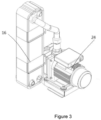
FIG 3 is a stereogram of a heat exchanger. - Referring to
FIG 1 , a schematic structural diagram of a heat exchange system according is shown. The heat exchange system comprises arefrigerant flow path 10 and a coolingmedium flow path 20. Refrigerant circulates in therefrigerant flow path 10. Therefrigerant flow path 10 may comprise acompressor 11, afirst heat exchanger 13, athrottling device 14 and asecond heat exchanger 16. In addition, therefrigerant flow path 10 may optionally comprise a four-way reversing valve 12, areservoir 15, a gas-liquid separator 17 and other components. In some cases, therefrigerant flow path 10 is entirely located in an outdoor unit 1. In an alternative embodiment, therefrigerant flow path 10 may also be partially located outdoors and partially indoors. On the other hand, the cooling medium circulates in the coolingmedium flow path 20. The cooling medium is usually water, which may freeze in low temperature environment. The coolingmedium flow path 20 comprises apump 24, asecond heat exchanger 16, and a plurality ofloads indoor unit 2. Therefore, the illustrated cooling medium flow path in the heat exchange system extends between theindoor unit 2 and the outdoor unit 1, thereby transferring thermal energy. It can be seen that both therefrigerant flow path 10 and the coolingmedium flow path 20 pass through thesecond heat exchanger 16, so that the refrigerant and cooling medium exchange heat in thesecond heat exchanger 16. More specifically, thesecond heat exchanger 16 comprises afirst refrigerant port 161, asecond refrigerant port 162, and the first flow path between thefirst refrigerant port 161 and thesecond refrigerant port 162. Thesecond heat exchanger 16 is connected to therefrigerant flow path 10 through thefirst refrigerant port 161 and thesecond refrigerant port 162. Thesecond heat exchanger 16 further comprises acooling medium inlet 163, acooling medium outlet 164, and the second flow path between thecooling medium inlet 163 and thecooling medium outlet 164. Thecooling medium inlet 163 and thecooling medium outlet 164 of thesecond heat exchanger 16 are connected to the coolingmedium flow path 20, and the refrigerant in the first flow path and the cooling medium in the second flow path exchange heat in thesecond heat exchanger 16. - The flow of the cooling medium in the
second heat exchanger 16 needs to be monitored so as to provide warning when the flow of cooling medium is low (e.g., to prevent freezing, leakage and the like), as the cooling capacity of the refrigerant may cause the cooling medium to freeze when the flow of cooling medium is relatively low.FIG 2 shows a solution of an existing design. A differentialpressure flow switch 19 is arranged between the first cooling medium port 163 (i.e. the cooling medium inlet) and the second cooling medium port 164 (i.e. the cooling medium outlet) of thesecond heat exchanger 16. It is connected to the cooling medium inlet and the cooling medium outlet respectively through apipeline 191, thus determining whether the flow is too low through differential pressure. However, since there is cooling medium in thepipeline 191 of the differentialpressure flow switch 19, the differential pressure flow switch itself has the risk of freezing. - In an embodiment, the heat exchange system further comprises a
first temperature sensor 168 at thecooling medium inlet 163 of the second heat exchanger, asecond temperature sensor 169 at thecooling medium outlet 164 of the second heat exchanger, and a controller (not shown) in communication with thefirst temperature sensor 168 and thesecond temperature sensor 169. The controller is configured to determine whether the flow of cooling medium in the heat exchanger is too low based on the temperature difference sensed by thefirst temperature sensor 168 and thesecond temperature sensor 169 during operation of the heat exchange system. For example, when the temperature difference is below or equal to the threshold, the flow is considered to be normal, and when the temperature difference is above the threshold, the flow is considered to be too low. The threshold can be obtained from empirical data. - In some embodiments, the controller also takes into account ambient temperature and the speed of the compressor when determining whether the flow of cooling medium in the heat exchanger is too low. For example, in some embodiments, warning thresholds for temperature differences at various ambient temperatures and compressor speeds are stored in the controller (e.g., in the form of a look-up table or model), and the controller is configured to determine whether the flow of cooling medium in the heat exchanger is too low based on a comparison between the actual sensed temperature difference and the warning threshold for temperature difference at the corresponding ambient temperature and compressor speed. If the actual monitored temperature difference at a specific ambient temperature and compressor speed is greater than the threshold for temperature difference at the ambient temperature and compressor speed, the flow is determined to be too low, or else the flow is determined to be normal. In some embodiments, the controller triggers the alarm and/or shuts down the heat exchange system when the flow of cooling medium is too low. And then, a worker can check the unit for leaks or other problems.
- The described system realizes monitoring of low cooling medium flow in the heat exchanger through temperature difference and logic control, which makes it possible to omit the use of differential pressure flow switch for cost savings and to avoid the failure of the differential pressure flow switch due to freezing. In some embodiments, as shown in
FIG 3 , a differential pressure flow switch may not be included between the cooling medium inlet and the cooling medium outlet of the heat exchanger. Alternatively, said device can also be a supplement to a differential pressure flow switch. - The operation period of a heat exchange system refers to the period during which the system operates stably, but not the unsteady-state period such as the start-up or state-switching period. During the unsteady-state period as mentioned above, because the temperature of the cooling medium is not yet stable and the temperature change of water is relatively slow due to its large thermal capacity, using temperature difference to determine whether the flow is too low will lead to larger errors. At this point, a compressor
suction pressure sensor 18 upstream of thecompressor 11 may be arranged in the refrigerant flow path of the heat exchange system. The controller determines whether the flow of the cooling medium in the heat exchanger is too low during the unsteady-state period of the heat exchange system, such as the start-up or state-switching period, based on the compressor suction pressure. That is, the actual measured compressor suction pressure is compared with the threshold of the compressor suction pressure, such that when the measured compressor suction pressure is below the threshold, it is determined that the flow of cooling refrigerant is too low, or else the flow of cooling refrigerant is within the normal range. - A method for determining whether the flow of cooling medium passing through a heat exchanger is too low in a heat exchange system is further provided. The heat exchange system may be the heat exchange system depicted in
FIGS. 1 and3 , which comprises: a refrigerant flow path, a cooling medium flow path and a heat exchanger. The aforementioned method comprises: determining whether the flow of cooling medium in the heat exchanger is too low based on the temperature difference between the cooling medium inlet of the heat exchanger and the cooling medium outlet of the heat exchanger during operation of the heat exchange system. This method makes it possible to omit the use of the differentialpressure flow switch 19, thereby saving system costs and avoiding problems caused by a malfunction of the differentialpressure flow switch 19. - According to some embodiments, the method further comprises: obtaining warning thresholds for temperature differences between the cooling medium inlet of the heat exchanger and the cooling medium outlet of the heat exchanger at various ambient temperatures and compressor speeds; and determining whether the flow of cooling medium in the heat exchanger is too low based on a comparison between the actual sensed temperature difference and the warning threshold for temperature difference at the corresponding ambient temperature and compressor speed. According to some embodiments, the method further comprises determining whether the flow of cooling medium in the heat exchanger is too low based on the suction pressure of the compressor during the start-up or state-switching period of the heat exchange system.
- The specific embodiments described above are merely intended to describe the principles of the present invention more clearly, wherein various components are clearly shown or described to facilitate the understanding of the principles of the present invention. Those skilled in the art may, without departing from the scope of the present invention, which is defined by the claims, make various modifications or changes to the described embodiment.
Claims (11)
- A heat exchange system comprising:a refrigerant flow path (10) in which refrigerant circulates and a compressor (11) is included;a cooling medium flow path (20) in which cooling medium circulates; anda heat exchanger (16) connected to both the refrigerant flow path (10) and the cooling medium flow path (20) so that the refrigerant and the cooling medium exchange heat in the heat exchanger (16),a first temperature sensor (168) arranged at a cooling medium inlet (163) of the heat exchanger (16),a second temperature sensor (169) arranged at a cooling medium outlet (164) of the heat exchanger (16), anda controller in communication with the first temperature sensor (168) and the second temperature sensor (169),wherein the controller is configured to determine whether flow of cooling medium in the heat exchanger (16) is too low based on a temperature difference sensed by the first temperature sensor (168) and the second temperature sensor (169) during operation of the heat exchange system.
- The heat exchange system according to claim 1, wherein the controller is further configured to determine whether the flow of cooling medium in the heat exchanger (16) is too low based on an ambient temperature and a speed of the compressor (11).
- The heat exchange system according to claim 2, wherein the controller is configured to store warning thresholds for temperature differences at various ambient temperatures and compressor speeds, and wherein the controller is configured to determine whether the flow of cooling medium in the heat exchanger (16) is too low based on a comparison between an actual sensed temperature difference and a warning threshold for a temperature difference at a corresponding ambient temperature and compressor speed.
- The heat exchange system according to claim 2 or 3, wherein the refrigerant flow path (10) comprises a pressure sensor (18) upstream of the compressor (11) for sensing an suction pressure of the compressor (11), and wherein the controller is configured to determine whether the flow of cooling medium in the heat exchanger (16) is too low based on the suction pressure of the compressor during a start-up or state-switching period of the heat exchange system.
- The heat exchange system according to any preceding claim, wherein the controller is configured to trigger an alarm when the flow of cooling medium is too low.
- The heat exchange system according to any preceding claim, wherein the controller is configured to shuts down the heat exchange system when the flow of cooling medium is too low.
- The heat exchange system according to any preceding claim, wherein the refrigerant flow path (10) and the heat exchanger (16) are located in an outdoor unit (1) and the cooling medium flow path (20) extends between the outdoor unit (1) and an indoor unit (2).
- The heat exchange system according to any preceding claim, wherein a differential pressure flow switch (19) is not included between the cooling medium inlet (163) and the cooling medium outlet (164) of the heat exchanger (16).
- A method for determining whether flow of cooling medium flowing through a heat exchanger (16) is too low in a heat exchange system, the heat exchange system comprising: a refrigerant flow path (10) in which refrigerant circulates and a compressor (11) is included; and a cooling medium flow path (20) in which cooling medium circulates; wherein the heat exchanger (16) is connected to both the refrigerant flow path (10) and the cooling medium flow path (20) so that the refrigerant and the cooling medium exchange heat in the heat exchanger (16), wherein the method comprises:
determining whether a flow of cooling medium in the heat exchanger (16) is too low based on a temperature difference between a cooling medium inlet (163) of the heat exchanger (16) and a cooling medium outlet (164) of the heat exchanger (16) during operation of the heat exchange system - The method according to claim 9, further comprising:setting warning thresholds for temperature differences between the cooling medium inlet (163) of the heat exchanger (16) and the cooling medium outlet (164) of the heat exchanger (16) at various ambient temperatures and compressor speeds; anddetermining whether the flow of cooling medium in the heat exchanger (16) is too low based on a comparison between an actual sensed temperature difference and a warning threshold for temperature difference at a corresponding ambient temperature and compressor speed.
- The method according to claim 9 or 10, further comprising:
determining whether the flow of cooling medium in the heat exchanger (16) is too low based on a suction pressure of the compressor (11) during a start-up or state-switching period of the heat exchange system.
Applications Claiming Priority (1)
| Application Number | Priority Date | Filing Date | Title |
|---|---|---|---|
| CN202210047176.7A CN116481211A (en) | 2022-01-17 | 2022-01-17 | Heat exchange system and method for judging whether flow of cold-carrying medium passing through heat exchanger is too low |
Publications (1)
| Publication Number | Publication Date |
|---|---|
| EP4212795A1 true EP4212795A1 (en) | 2023-07-19 |
Family
ID=84981359
Family Applications (1)
| Application Number | Title | Priority Date | Filing Date |
|---|---|---|---|
| EP23151623.8A Pending EP4212795A1 (en) | 2022-01-17 | 2023-01-13 | Heat exchanging system and method for determining if the flow of cooling medium is too low |
Country Status (3)
| Country | Link |
|---|---|
| US (1) | US12339072B2 (en) |
| EP (1) | EP4212795A1 (en) |
| CN (1) | CN116481211A (en) |
Families Citing this family (1)
| Publication number | Priority date | Publication date | Assignee | Title |
|---|---|---|---|---|
| CN119255575B (en) * | 2024-12-03 | 2025-03-04 | 依米康科技集团股份有限公司 | Control method and system of liquid cooling heat dissipation system |
Citations (3)
| Publication number | Priority date | Publication date | Assignee | Title |
|---|---|---|---|---|
| JP2009243828A (en) * | 2008-03-31 | 2009-10-22 | Mitsubishi Electric Corp | Cooling device and cooling device monitoring system |
| EP3217112A1 (en) * | 2014-11-05 | 2017-09-13 | Mitsubishi Electric Corporation | Refrigeration cycle device |
| EP3477221B1 (en) * | 2016-06-23 | 2020-01-29 | Mitsubishi Electric Corporation | Heat medium circulation system |
Family Cites Families (8)
| Publication number | Priority date | Publication date | Assignee | Title |
|---|---|---|---|---|
| CN102549356B (en) * | 2009-08-17 | 2014-12-24 | 江森自控科技公司 | Heat-pump chiller with improved heat recovery features |
| US10113553B2 (en) * | 2016-01-12 | 2018-10-30 | Daikin Applied Americas Inc. | Centrifugal compressor with hot gas injection |
| JP6835651B2 (en) * | 2017-03-31 | 2021-02-24 | 三菱重工サーマルシステムズ株式会社 | Refrigerator controller, turbo chiller, chiller control method and program |
| US11448438B2 (en) * | 2019-10-21 | 2022-09-20 | Thermo King Corporation | Transport climate control system with auxilary cooling |
| JP7559394B2 (en) * | 2020-07-17 | 2024-10-02 | Smc株式会社 | Chiller |
| US12158165B2 (en) * | 2021-03-10 | 2024-12-03 | Daikin Industries, Ltd. | Centrifugal compressor with liquid injection |
| US11549717B2 (en) * | 2021-03-31 | 2023-01-10 | Trane International Inc. | Online optimization of variable frequency drive compression efficiency |
| US20240247850A1 (en) * | 2021-07-08 | 2024-07-25 | Mitsubishi Electric Corporation | Heat pump system |
-
2022
- 2022-01-17 CN CN202210047176.7A patent/CN116481211A/en active Pending
-
2023
- 2023-01-13 US US18/154,063 patent/US12339072B2/en active Active
- 2023-01-13 EP EP23151623.8A patent/EP4212795A1/en active Pending
Patent Citations (3)
| Publication number | Priority date | Publication date | Assignee | Title |
|---|---|---|---|---|
| JP2009243828A (en) * | 2008-03-31 | 2009-10-22 | Mitsubishi Electric Corp | Cooling device and cooling device monitoring system |
| EP3217112A1 (en) * | 2014-11-05 | 2017-09-13 | Mitsubishi Electric Corporation | Refrigeration cycle device |
| EP3477221B1 (en) * | 2016-06-23 | 2020-01-29 | Mitsubishi Electric Corporation | Heat medium circulation system |
Also Published As
| Publication number | Publication date |
|---|---|
| US20230228504A1 (en) | 2023-07-20 |
| CN116481211A (en) | 2023-07-25 |
| US12339072B2 (en) | 2025-06-24 |
Similar Documents
| Publication | Publication Date | Title |
|---|---|---|
| CN108633225B (en) | Air conditioning system for machine room | |
| JP5761960B2 (en) | Heat source equipment | |
| EP3734177B1 (en) | Control method for air conditioner | |
| US20090151388A1 (en) | Dedicated heat recovery chiller | |
| CN110895023A (en) | Air conditioner refrigerant leakage detection method and air conditioner | |
| JP5492523B2 (en) | Air conditioner | |
| JP7656179B2 (en) | Refrigerant leak detection system, method, and program | |
| JPWO2017221383A1 (en) | Heat medium circulation system | |
| CN114992776B (en) | Refrigerant leakage detection method and device for air conditioning system, air conditioner and storage medium | |
| CN107477897A (en) | A kind of computer-room air conditioning system and its control method | |
| JP6817787B2 (en) | Air conditioner | |
| CN104807141A (en) | Multi-split air conditioner control method and system thereof | |
| US12339072B2 (en) | Heat exchanging system and method for determining if the flow of cooling medium is too low | |
| CN101413768A (en) | Anti-freeze protection device and method | |
| CN105157295A (en) | Refrigeration system and control method and control device thereof | |
| CN108050719A (en) | A kind of Cooling System and its control method based on differential thermal calculation refrigerated medium pump ability | |
| JP6538420B2 (en) | Air conditioning system | |
| US8555670B2 (en) | Power consumption economizer for refrigerating machines of the chiller type | |
| CN114294737B (en) | Refrigeration system, control method and air conditioner | |
| US20250012467A1 (en) | Protection method and device for high-temperature prevention during heating and refrigerant shortage during heating, and air conditioning system | |
| JP2008224155A (en) | Ice storage type heat source apparatus and control method thereof | |
| CN109764577B (en) | Low-temperature heat pump system and control method of reversing valve thereof | |
| CN104279789A (en) | Triple co-generation air conditioner system | |
| CN114710941A (en) | Control system of air-cooled heat dissipation system for radar electronic cabinet | |
| CN219283572U (en) | Dehumidifier heat exchanger air blocking early warning device |
Legal Events
| Date | Code | Title | Description |
|---|---|---|---|
| PUAI | Public reference made under article 153(3) epc to a published international application that has entered the european phase |
Free format text: ORIGINAL CODE: 0009012 |
|
| STAA | Information on the status of an ep patent application or granted ep patent |
Free format text: STATUS: THE APPLICATION HAS BEEN PUBLISHED |
|
| AK | Designated contracting states |
Kind code of ref document: A1 Designated state(s): AL AT BE BG CH CY CZ DE DK EE ES FI FR GB GR HR HU IE IS IT LI LT LU LV MC ME MK MT NL NO PL PT RO RS SE SI SK SM TR |
|
| STAA | Information on the status of an ep patent application or granted ep patent |
Free format text: STATUS: REQUEST FOR EXAMINATION WAS MADE |
|
| 17P | Request for examination filed |
Effective date: 20240119 |
|
| RBV | Designated contracting states (corrected) |
Designated state(s): AL AT BE BG CH CY CZ DE DK EE ES FI FR GB GR HR HU IE IS IT LI LT LU LV MC ME MK MT NL NO PL PT RO RS SE SI SK SM TR |
|
| STAA | Information on the status of an ep patent application or granted ep patent |
Free format text: STATUS: EXAMINATION IS IN PROGRESS |
|
| 17Q | First examination report despatched |
Effective date: 20250102 |