EP4212743A1 - Élément d'ancrage destiné à être ancré dans un puits de forage, ensemble d'ancrage comprenant un tel élément d'ancrage et procédé de fabrication d'un tel ensemble d'ancrage - Google Patents
Élément d'ancrage destiné à être ancré dans un puits de forage, ensemble d'ancrage comprenant un tel élément d'ancrage et procédé de fabrication d'un tel ensemble d'ancrage Download PDFInfo
- Publication number
- EP4212743A1 EP4212743A1 EP23150083.6A EP23150083A EP4212743A1 EP 4212743 A1 EP4212743 A1 EP 4212743A1 EP 23150083 A EP23150083 A EP 23150083A EP 4212743 A1 EP4212743 A1 EP 4212743A1
- Authority
- EP
- European Patent Office
- Prior art keywords
- anchoring
- anchoring element
- coupling
- tension
- borehole
- Prior art date
- Legal status (The legal status is an assumption and is not a legal conclusion. Google has not performed a legal analysis and makes no representation as to the accuracy of the status listed.)
- Pending
Links
- 238000004873 anchoring Methods 0.000 title claims abstract description 278
- 238000004519 manufacturing process Methods 0.000 title claims description 9
- 238000010168 coupling process Methods 0.000 claims abstract description 104
- 238000005859 coupling reaction Methods 0.000 claims abstract description 104
- 230000008878 coupling Effects 0.000 claims abstract description 102
- 239000000463 material Substances 0.000 claims abstract description 42
- 238000005520 cutting process Methods 0.000 claims abstract description 28
- 230000005540 biological transmission Effects 0.000 claims abstract description 19
- 230000006835 compression Effects 0.000 claims description 114
- 238000007906 compression Methods 0.000 claims description 114
- 238000000034 method Methods 0.000 claims description 10
- 238000003825 pressing Methods 0.000 description 11
- 238000013461 design Methods 0.000 description 8
- 238000007373 indentation Methods 0.000 description 5
- 238000005192 partition Methods 0.000 description 5
- 230000003014 reinforcing effect Effects 0.000 description 5
- 238000005260 corrosion Methods 0.000 description 4
- 230000007797 corrosion Effects 0.000 description 4
- 239000003795 chemical substances by application Substances 0.000 description 3
- 238000009826 distribution Methods 0.000 description 3
- 239000003822 epoxy resin Substances 0.000 description 3
- 239000004570 mortar (masonry) Substances 0.000 description 3
- 229920000647 polyepoxide Polymers 0.000 description 3
- 238000003466 welding Methods 0.000 description 3
- 239000004743 Polypropylene Substances 0.000 description 2
- 239000000853 adhesive Substances 0.000 description 2
- 238000004026 adhesive bonding Methods 0.000 description 2
- 230000001070 adhesive effect Effects 0.000 description 2
- 238000005553 drilling Methods 0.000 description 2
- 238000003780 insertion Methods 0.000 description 2
- 230000037431 insertion Effects 0.000 description 2
- 239000000088 plastic resin Substances 0.000 description 2
- -1 polypropylene Polymers 0.000 description 2
- 229920001155 polypropylene Polymers 0.000 description 2
- 230000002787 reinforcement Effects 0.000 description 2
- 238000010079 rubber tapping Methods 0.000 description 2
- 229910000831 Steel Inorganic materials 0.000 description 1
- 239000012790 adhesive layer Substances 0.000 description 1
- 239000002131 composite material Substances 0.000 description 1
- 238000010276 construction Methods 0.000 description 1
- 238000011161 development Methods 0.000 description 1
- 230000018109 developmental process Effects 0.000 description 1
- 239000000835 fiber Substances 0.000 description 1
- 239000004519 grease Substances 0.000 description 1
- 230000001771 impaired effect Effects 0.000 description 1
- 230000010354 integration Effects 0.000 description 1
- 239000002245 particle Substances 0.000 description 1
- 239000004033 plastic Substances 0.000 description 1
- 230000036316 preload Effects 0.000 description 1
- 239000011435 rock Substances 0.000 description 1
- 239000010959 steel Substances 0.000 description 1
- 238000012546 transfer Methods 0.000 description 1
- 230000007704 transition Effects 0.000 description 1
- 239000002023 wood Substances 0.000 description 1
Images


Classifications
-
- F—MECHANICAL ENGINEERING; LIGHTING; HEATING; WEAPONS; BLASTING
- F16—ENGINEERING ELEMENTS AND UNITS; GENERAL MEASURES FOR PRODUCING AND MAINTAINING EFFECTIVE FUNCTIONING OF MACHINES OR INSTALLATIONS; THERMAL INSULATION IN GENERAL
- F16B—DEVICES FOR FASTENING OR SECURING CONSTRUCTIONAL ELEMENTS OR MACHINE PARTS TOGETHER, e.g. NAILS, BOLTS, CIRCLIPS, CLAMPS, CLIPS OR WEDGES; JOINTS OR JOINTING
- F16B25/00—Screws that cut thread in the body into which they are screwed, e.g. wood screws
- F16B25/001—Screws that cut thread in the body into which they are screwed, e.g. wood screws characterised by the material of the body into which the screw is screwed
- F16B25/0026—Screws that cut thread in the body into which they are screwed, e.g. wood screws characterised by the material of the body into which the screw is screwed the material being a hard non-organic material, e.g. stone, concrete or drywall
-
- F—MECHANICAL ENGINEERING; LIGHTING; HEATING; WEAPONS; BLASTING
- F16—ENGINEERING ELEMENTS AND UNITS; GENERAL MEASURES FOR PRODUCING AND MAINTAINING EFFECTIVE FUNCTIONING OF MACHINES OR INSTALLATIONS; THERMAL INSULATION IN GENERAL
- F16B—DEVICES FOR FASTENING OR SECURING CONSTRUCTIONAL ELEMENTS OR MACHINE PARTS TOGETHER, e.g. NAILS, BOLTS, CIRCLIPS, CLAMPS, CLIPS OR WEDGES; JOINTS OR JOINTING
- F16B37/00—Nuts or like thread-engaging members
- F16B37/12—Nuts or like thread-engaging members with thread-engaging surfaces formed by inserted coil-springs, discs, or the like; Independent pieces of wound wire used as nuts; Threaded inserts for holes
- F16B37/122—Threaded inserts, e.g. "rampa bolts"
- F16B37/125—Threaded inserts, e.g. "rampa bolts" the external surface of the insert being threaded
- F16B37/127—Threaded inserts, e.g. "rampa bolts" the external surface of the insert being threaded and self-tapping
Definitions
- the invention relates to an anchoring element for anchoring in a borehole, an anchoring arrangement with such an anchoring element and a method for producing such an anchoring arrangement.
- the invention is based on the object of creating an improved anchorage, in particular for deep boreholes, in which case, in particular, the effort involved in producing the anchoring element and/or the production of the anchorage is reduced.
- an anchoring element and a tension/compression element can be detachably coupled to one another.
- This makes it possible to anchor the anchoring element in a drilled hole in a material independently of the tension/compression element.
- the outlay for anchoring, in particular screwing the anchoring element into the borehole, is reduced as a result.
- the anchoring element and the tension/compression element form an anchoring unit that is designed in several parts.
- the anchoring element is suitable in particular for anchoring in a drilled hole in a material, in particular in a hard material, in particular in concrete.
- the anchoring element can also be anchored in a borehole in the ground, rock, steel, plastic or in wood.
- the borehole is designed as a stepped borehole with an inner borehole section that has a first diameter and an outer borehole section that has a second diameter Having a diameter that is greater than the first diameter.
- the second diameter is larger than an outer diameter of the anchoring element, in particular than a thread diameter of a cutting thread of the anchoring element.
- a stepped bore can be used in particular when using a second anchoring element, in which case the second anchoring element can be embodied on the inside, ie with a self-tapping external thread, or as an external end anchorage.
- a longitudinal axis of the borehole is in particular oriented perpendicular to an outer surface of the material surrounding the borehole. This simplifies the drilling of the borehole into the material.
- the borehole longitudinal axis is inclined relative to the surface of the material, with an angle of inclination being less than 90° and in particular greater than or equal to 30°, in particular greater than or equal to 45°, in particular greater than or equal to 60° , in particular greater than or equal to 70°, in particular greater than or equal to 75°, in particular greater than or equal to 80°, in particular greater than or equal to 85° and in particular greater than or equal to 88°.
- external anchoring can take place particularly advantageously in that the external anchoring element uses a wedge disk and/or a wedge ring disk, which is also referred to as a Nord-Lock disk.
- the anchoring element has a sleeve-shaped base body.
- the sleeve body has a longitudinal axis.
- a cutting thread is arranged on the sleeve base body and is in particular formed in one piece on the sleeve base body.
- the cutting thread is in particular an external thread.
- the cutting thread extends on the sleeve body along the longitudinal axis over at least one complete rotation, in particular at least 1.5 rotations, in particular at least two rotations, in particular at least 2.5 rotations, in particular at least three rotations and in particular at least four rotations.
- the cutting thread on the sleeve body extends along at least 50% of its length, in particular at least 60% of the length, in particular at least 70% of the length, in particular at least 80% of the length, in particular at least 90% of the length, in particular of at least 95% of the length and in particular along the full length of the sleeve body.
- the cutting thread enables a thread helix to be cut directly and immediately into an inner wall of the borehole.
- a coupling section is arranged on the sleeve base body, in particular formed in one piece on the sleeve base body.
- the coupling section is arranged in particular on an inside of the sleeve base body, ie inside the sleeve.
- the tension/compression element is designed in particular in the form of a bar or rod.
- the tension/compression element has a cross-sectional area which essentially has a round outer contour on which an external thread can be attached in particular. It is also conceivable that the cross-sectional area has a non-round outer contour, in particular a polygonal outer contour, in particular square, hexagonal or octagonal. In particular, the length of the tension/compression element is greater and in particular significantly greater than a maximum diameter of the cross-sectional area.
- the length is at least five times, in particular at least ten times, in particular at least twenty times, in particular at least twenty-five times, in particular at least fifty times, in particular at least one hundred times, in particular at least five hundred times and in particular at most one thousand times the maximum diameter of the cross-sectional area.
- the tension/compression element is used in particular to transmit tension and/or compression.
- the tension/compression element is designed in particular as a reinforcement bar and can in particular have an external thread, in particular an external coarse thread, a metric external thread and/or an external fine thread.
- a torque transmission section is arranged on the sleeve base body and is in particular formed in one piece on the sleeve base body.
- the torque transmission section serves to transmit a screwing torque to the sleeve base body. This makes it easier to apply a screwing torque to the sleeve base body using a tool.
- An anchoring element simplifies the coupling of a tool to the sleeve body for transmitting the screwing torque.
- the tool can attack the front of the sleeve body. This favors the torque transmission.
- the sleeve base body has, in particular, an end face in the form of an annular surface.
- the torque transmission section is designed in particular eccentrically with respect to the longitudinal axis on the sleeve base body, in particular as elevations and/or depressions in pairs on the end face of the sleeve base body. This improves a form fit for the tool.
- a non-round contour in a plane oriented perpendicularly to the longitudinal axis can be designed as a non-round inner contour or non-round outer contour.
- a non-round outer contour is formed in particular by an elevation and/or a depression on the end face of the sleeve base body that is in the form of an annular surface.
- the non-round contour can also be configured as a polygon contour, in particular as a hexagonal contour, which is configured, for example, on an inside of the sleeve base body.
- a hexagon socket contour on the inside of the sleeve base body can be designed in such a way that the coupling with the push/pull element is unimpaired.
- a clear width of the inner contour is larger than an inner diameter of the coupling section.
- a non-round outer contour in particular as an outer hexagonal contour, can be applied to a section of the sleeve base body. It goes without saying that in this case a maximum outer diameter of the non-round outer contour is smaller than the thread diameter of the cutting thread.
- An anchoring element enables uncomplicated torque transmission.
- a tool with an external thread can be screwed into a corresponding internal thread of the sleeve base body up to the axial stop on a bottom surface of the sleeve base body.
- the internal thread can include a coarse thread, a metric thread and/or a fine thread. The design of the torque transmission section on the sleeve body is simplified.
- the design of the anchoring element according to claim 5 is uncomplicated. It is particularly advantageous if the sleeve base body has a continuous bore oriented along the longitudinal axis. This bore has a round outer contour in a plane perpendicular to the longitudinal axis. It is conceivable that the outer contour of the bore, at least in sections, is non-circular, in particular polygonal. The bore can also only extend over a partial section of the sleeve base body, in particular along at least 50% of the length of the sleeve base body, in particular along at least 60%, in particular along at least 70%, in particular along at least 80%, in particular along at least 90% and in particular along at least 95%.
- the basic sleeve body is designed in particular in the form of a cap.
- An anchoring element according to claim 6 enables a direct and uncomplicated coupling of the anchoring element to the tension/compression element.
- the internal thread in the sleeve base body serves both as a coupling section and as a torque transmission section.
- Such an anchoring element has increased functional integration. The construction and design of the anchoring element are simplified because the number of functional elements or functional sections is reduced. In particular, there is no need to provide a separate coupling section and a separate torque transmission section.
- An anchoring element according to claim 7 enables an efficient coupling between the anchoring element and the tension/compression element.
- An anchoring arrangement according to claim 8 essentially has the advantages of the anchoring element according to claim 1, to which reference is hereby made.
- an outside diameter of the tension/compression element is smaller than the thread diameter of the anchoring element. The tension/compression element can be introduced into the borehole essentially without contact and guided to the anchoring element and coupled thereto.
- An anchoring arrangement according to claim 9 simplifies the application of compressive stresses into the material.
- a second anchoring element is used for this purpose, which is designed in particular according to the invention and is designed in particular identically to the first anchoring element.
- An anchoring arrangement according to claim 10 has increased flexibility when applying and arranging the second anchoring element.
- An anchoring arrangement according to claim 11 simplifies the coupling of the tension/compression element to the anchoring element by means of a screw connection.
- An anchoring arrangement enables a targeted coupling of the tension/compression element to the anchoring element.
- Coupling to the anchoring element can be simplified by means of at least one coupling element, which is coupled to the tension/compression element. In particular, this can increase the security of the coupling between the tension/compression element and the anchoring element.
- a lock nut can serve as the coupling element, in particular in a standard design and/or in a large design.
- a conical element or a clamping sleeve can also serve as a coupling element.
- the respective coupling element has in particular a counter-coupling section which can be detachably coupled to the coupling section of the anchoring element. It is conceivable that the coupling element is firmly and, in particular, non-releasably coupled to the push/pull element, that is to say it is connected.
- a method according to claim 13 simplifies the manufacture of the anchoring arrangement.
- the detachable coupling of the tension/compression element to the anchoring element and the anchoring of the anchoring element in the borehole are separate method steps.
- a method according to claim 14 enables reliable and uncomplicated coupling.
- a method according to claim 15 enables simplified screwing in of the anchoring element.
- a borehole 3 is arranged in a material 2 , in particular concrete, and extends along a longitudinal axis 5 of the borehole, starting from an upper side 4 of the material 2 .
- the borehole 3 has a borehole diameter DB and a borehole depth T B .
- the borehole depth T B corresponds to the longitudinal extent of the borehole 3 along the longitudinal axis 5 of the borehole, starting from the upper side 4.
- the borehole 3 is a deep borehole.
- TB >5 ⁇ DB in particular TB >10 ⁇ DB , in particular TB ⁇ 20 ⁇ DB , in particular TB ⁇ 25 ⁇ DB , in particular TB ⁇ 50 ⁇ DB , in particular TB ⁇ 100 x DB and in particular TB ⁇ 1000 x DB .
- An anchoring element 6 is arranged in the borehole 3 , in particular adjacent to the bottom of the borehole, that is to say the inner end of the borehole 3 opposite the top side 4 , and is anchored in the borehole 3 .
- the anchoring element 6 has a cutting thread 7 which is designed as an external thread.
- a reinforcing bar 8 is detachably coupled to the anchoring element 6 at its first end.
- the reinforcing bar is a tension/compression element 8.
- the anchoring element 6 and the tension/compression element 8 form an anchoring unit.
- At its second end is the push/pull element 8 with a second anchoring element 9, in particular also releasably coupled.
- the tension/compression element 8 can also be permanently coupled to the anchoring element 6 and/or to the second anchoring element 9, in particular glued, welded and/or mechanically joined, in particular by forming, in particular by pressing.
- the second anchoring element 9 is designed in particular similarly and in particular identically to the first anchoring element 6 and has in particular a cutting thread 7 .
- the cutting thread 7 of the second anchoring element 9 is designed with the reverse orientation.
- the cutting thread 7 on the second anchoring element 9 is designed as a so-called left-hand thread. It is also conceivable that both cutting threads 7 are designed with the same orientation.
- the tension/compression element 8 is coupled to the two anchoring elements 6, 9 and the anchoring elements 6, 9 are anchored in the borehole 3, the tension/compression element 8 can pull along the longitudinal axis 5 of the borehole. and/or transfer pressure forces.
- the borehole longitudinal axis 5 and thus also the longitudinal orientation of the anchoring unit 6, 9 is oriented horizontally.
- the orientation of the anchoring unit is inclined relative to the horizontal and, in particular, is oriented perpendicular thereto, ie vertically.
- FIG. 2 shows an alternative embodiment of an anchoring arrangement 1, which essentially corresponds to the previous embodiment.
- the second anchoring element 10 is arranged outside the borehole and is supported in particular on the upper side 4 of the material 2 .
- the second anchoring element 10 is designed in particular as a fastening nut with an internal thread that corresponds to an external thread of the tension/compression element.
- the external thread of the tension/compression element 8 is an external coarse thread.
- the fastening nut 10 is in particular screwed directly onto the tension/compression element 8 and is supported on the upper side 4 by means of a load distribution disk.
- the tension/compression element 8 is used exclusively for the transmission of tension forces, i.e. it is a tension element.
- a preload can be adjusted in a targeted manner.
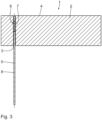
- the anchoring arrangement 1 according to 3 differs from the two previous anchoring arrangements in that only one anchoring element 6 is provided, which is anchored in the borehole 3.
- the reinforcing bar 8 is detachably coupled to the anchoring element 6 .
- the borehole 3 is designed as a continuous borehole in the material 2 .
- the borehole 3 can also be designed as a blind hole.
- the reinforcing bar 8 serves as a tension element, as a compression element or as a combined tension/compression element.
- the borehole longitudinal axis 5 is oriented vertically.
- the tension/compression element 8 is also referred to as a tension/compression pile.
- the anchoring element 6 has a base body 12 which is designed essentially like a sleeve.
- the base body is a sleeve base body 12 .
- the sleeve base body 12 has a longitudinal axis 13 .
- the sleeve base body 12 is hollow-cylindrical with respect to the longitudinal axis 13 and has an outer sleeve diameter D H which is constant along the longitudinal axis 13 according to the exemplary embodiment shown.
- the sleeve base body 12 has a bore 14, which, starting from an end face 15, which 4 shown on the left, extends along the longitudinal axis 13 .
- the bore 14 has a depth T along the longitudinal axis 13 which, according to the exemplary embodiment shown, is less than the total length L total of the anchoring element 6. It is advantageous if the following applies: L total ⁇ 0.5 x T, in particular L total ⁇ 0 .6 x T, in particular L tot ⁇ 0.7 x T, in particular L tot ⁇ 0.8 x T, in particular L tot ⁇ 0.9 x T and in particular L tot ⁇ 0.95 x T.
- the sleeve base body 12 is designed in the shape of a cap. It is also conceivable that the bore 14 is designed to be continuous, that is to say that the basic sleeve body 12 is designed without a sleeve base.
- the cutting thread 7 extends over four revolutions and in particular along the longitudinal axis 13 only partially along the total length L tot .
- the cutting thread 7 has a thread diameter D G which is larger than the sleeve diameter D H .
- the thread diameter D G is larger than the drill hole diameter DB .
- the drill hole diameter DB is larger than the sleeve diameter D H .
- the anchoring element 6 has on the end face 15, which is designed in the shape of an annular surface, two slot-like depressions 17 which form a torque transmission section.
- the depressions 17 are arranged diametrically opposite one another. It is conceivable that only one depression 17 or more than two depressions 17 are provided. In particular, it is conceivable that the distance between two adjacent depressions 17 in the circumferential direction is greater or less than 180°. In particular, the distance is evenly distributed in the circumferential direction in the case of a plurality of indentations 17 .
- the side flanks 18 of the respective depression 17 are oriented radially with respect to the longitudinal axis 13 .
- the respectively corresponding side flanks 18 of the opposite indentations 17 are arranged in a common radial plane 19 which contains the longitudinal axis 13 .
- These radial planes 19 are in figure 5 drawn in and run perpendicular to the plane of the drawing figure 5 .
- the depressions 17 allow, for example, an uncomplicated placement of a tool insert, which can be designed, for example, in the form of a slotted screwdriver.
- the depressions 17 each taper along the longitudinal axis 13 starting from the end face 15 . This simplifies and improves the insertion of the tool into the depressions 17 and its stable, non-slip arrangement in the depression 17 .
- a coupling section 20 is formed on an inside of the sleeve base body 12 .
- the coupling section 20 is designed as an internal coarse thread, which is formed in particular in one piece on the inside of the sleeve base body 12 .
- the coupling section 20 extends along the longitudinal axis 13 at most to the depth T of the bore 14 and in particular over at least 50% of the depth T, in particular at least 70% of the depth T and in particular at least 90% of the depth T.
- the anchoring element 6 can be screwed into a drilled hole 3 by means of the tool which engages in the recesses 17 and cut into the drilled hole 3 with the cutting thread 7 .
- the anchoring element 6 is then arranged anchored in the borehole 3 .
- the tool is then removed and a tension/compression element 8 is inserted into the borehole 3 up to the anchoring element 6 and then coupled to the anchoring element 6 already anchored in the borehole 3, in particular by the tension/compression element 8 having a coupling thread is screwed to the coupling section 20 .
- the tension/compression element 8 may be permanently coupled to the anchoring element 6 .
- the anchoring unit thus formed is produced before the anchoring unit is anchored in the borehole 3.
- initially Anchoring element 6 is anchored in the borehole 3 and the tension/compression element 8 is joined to the already anchored anchoring element, that is to say is inextricably coupled.
- the torque transmission section is formed by two circular indentations 17a.
- the indentations 17a each have a closed outer contour, with the respective closed outer contour being arranged completely within the annular end face 15 .
- the outer contour can be round or non-round. It is advantageous if the closed outer contour is arranged eccentrically to the longitudinal axis 13 .
- the depressions 17a are in particular designed as blind bores, which extend from the end face 15 along the longitudinal axis 13 .
- the anchoring element 6b has a cutting thread 7 which extends along the entire length L tot of the sleeve base body 12 .
- the bore 14 is designed to be continuous.
- the tension/compression element 8 is passed completely through the bore 14 of the anchoring element 6b.
- the tension/compression element 8 has an external coarse thread 21, which represents a coupling thread and corresponds to the coupling section 20 of the anchoring element 6b.
- the tension/compression element 8 is detachably coupled with the coupling thread 21 to the anchoring element 6b.
- a coupling element 22 in the form of a lock nut is arranged at the end shown above, with which the tension/compression element 8 is passed through the anchoring element 6b.
- the lock nut 22 has an internal thread that corresponds to the coupling thread 21 .
- the anchoring element 6b is pre-locked to the tension/compression element 8 by means of the lock nut 22, ie fixed thereto.
- the lock nut 22 minimizes the risk of the anchoring element 6b unintentionally detaching from the tension/compression element 8 when cutting into the borehole 3 .
- a second coupling element 22 is provided in the anchoring arrangement 1, according to 7 is arranged below the anchoring element 6b.
- the second coupling element 22 is also designed as a lock nut, which is in particular identical to the other lock nut 22 .
- the anchoring element 6b is therefore countered to the tension/compression element 8 on both sides.
- the anchoring unit with the anchoring element 6b and the tension/compression element 8 and the additionally provided lock nuts 22 enable improved corrosion protection, in particular for the coupling thread 21 and the coupling section 20.
- the reliability of the connection between the anchoring element 6b and the tension/compression -Element 8 and thus the reliability of the anchoring unit 1 as a whole are thereby increased.
- the connection between the anchoring element 6b and the tension / compression element 8 can in particular by a Metric thread and in particular are made possible by a fine thread.
- the anchoring arrangement 1 if the anchoring unit, ie the anchoring element 6b with the tension/compression element 8, is coupled to one another before being screwed into the borehole 3 and is pre-locked by means of the lock nuts 22.
- the anchoring unit can then be screwed into the borehole 3 in the preassembled arrangement.
- the preassembled arrangement can also include that the tension/compression element 8 is permanently coupled to the anchoring element 6b, in particular by gluing.
- the anchoring arrangement 1 according to 8 corresponds essentially to that according to 7 , improved protection against corrosion being ensured by a shrink tube 23 which surrounds the tension/compression element 8 and is arranged in particular in the radial direction between the anchoring element 6b and the tension/compression element 8 .
- the shrink tube 23 extends so far that it protrudes on both sides of the anchoring element 6b.
- the shrink tube 23 extends along the longitudinal axis 5 of the borehole over at least two, in particular at least three, in particular at least four and in particular at least five thread turns of the coupling thread 21.
- the shrink tube 23 can also be arranged at a distance from the anchoring element 6b along the longitudinal axis 5 of the borehole and in particular as corrosion protection for the tension/compression element 8 .
- the shrink tube 23 is made in particular from a stable material and in particular forms an inherently stable element which can also be referred to as a casing tube or corrugated tube.
- the enveloping tube or corrugated tube 23 has transverse ribs on its outside, which are in particular spaced apart axially and are in particular designed regularly.
- the sleeve or corrugated tube corresponds to a drainage hose.
- the shrink tube and/or the sleeve tube or corrugated tube 23 prevents direct, in particular metallic, contact between the coupling thread 21 of the tension/compression element 8 and the tension/compression element 8 itself and an in 8 not shown filling material of the borehole 3.
- The, in particular ring-shaped space between the tension / compression element 8 and the shrink tube 23 can be compressed with a filling material, in particular grease. This improves the protection against corrosion.
- Coupling elements in the form of lock nuts can be dispensed with by using the shrink tube 23. However, it is still possible to screw lock nuts onto the coupling thread 21 and under the shrink tube 23 and/or the jacket tube or the corrugated tube.
- the arrangement shown shows the anchoring element 6b with the two lock nuts 22.
- a significant difference compared to the version in 7 is that two separate tension/compression elements 8 are coupled to one another in the anchoring element 6b.
- the two tension/compression elements 8 are arranged at a distance from one another in the axial direction relative to the longitudinal axis 13 within the anchoring element 6b by a separating region 24 .
- the separating area 24 has no structural element, ie it is a gap within the sleeve base body 12.
- the separating area 24 has an axial extent along the longitudinal axis 13 .
- the two tension/compression elements 8 are screwed into the anchoring element 6b in such a way that they abut one another on the end face at the separating area 24 .
- the separating area 24 is designed as a separating plane which is oriented perpendicularly to the longitudinal axis 13 .
- the anchoring element 6b according to 9 is a coupling element since it couples two separate tension/compression elements 8 to one another.
- the anchoring element 6b can be used in particular as a reinforcement connection.
- a method is conceivable in which an anchoring unit is anchored in a borehole with a pre-locked tension/compression element 8 and a further tension/compression element 8 is subsequently detachably coupled to the anchoring element 6b.
- one of the tension/compression elements 8 or both tension/compression elements 8 are non-detachably coupled to the anchoring element 6b.
- the sleeve diameter D H is not provided along the entire length L tot .
- the anchoring element 6c is designed as a so-called anchor piece, with a sleeve section 26 with the sleeve diameter D H is connected to a pin section 25 which is in particular made in one piece with the sleeve section 26 .
- the bore 14 with the coupling section 20 designed as an internal thread is designed to be continuous.
- the spigot section 25 has an outside diameter Dz which is smaller than the outside diameter D H of the sleeve section 26, in particular is at most 80% of the sleeve diameter.
- D Z ⁇ 0.75 ⁇ D H in particular D Z ⁇ 0.7 ⁇ D H
- D Z ⁇ 0.6 ⁇ D H in particular D Z ⁇ 0.5 ⁇ D H and in particular D Z ⁇ 0.3 x D H .
- the spigot section 25 is in particular designed without an external thread.
- the pin section 25 has a non-round outer contour, in particular an outer hexagonal contour.
- the non-round outer contour of the pin section 25 serves as a torque transmission section and thus simplifies the screwing of the anchoring element 6c into a borehole using a tool, in particular the mechanical screwing of the anchoring element 6c into a borehole.
- the cutting thread 7 is arranged exclusively on the sleeve section 26 .
- the bore 14d of the anchoring element 6d is of cylindrical design, in particular without a thread. What is essential in this exemplary embodiment is that a minimum inner diameter D i,min of the bore 14d is greater than a maximum outer diameter D a,max of the tension/compression element 8.
- the maximum outer diameter D a,max of the tension/compression element 8 corresponds to the outer diameter of the coupling thread 21. This means that the tension/compression element 8 is guided essentially without contact through the anchoring element 6d, in particular through the bore 14d.
- the coupling element 22d is designed like a nut and has an internal thread that corresponds to the coupling thread 21 of the push/pull element 8 .
- the coupling element 22d has an outside diameter that is larger than the minimum inside diameter D i , min .
- the coupling element 22d has a cone surface 27 which defines a cone angle k which is defined with respect to a plane oriented perpendicularly to the longitudinal axis 13 . According to the exemplary embodiment shown, the cone angle k is 30°.
- the cone angle can also be larger or smaller than 30° and is in particular between 15° and 60°.
- the anchoring element 6d is coupled indirectly to the tension/compression element 8 via the coupling element 22d.
- the conical surface 27 of the coupling element 22d rests against a corresponding support surface 28 on the sleeve base body 12 at the end face.
- the coupling element 22d is used in particular as a support for tensile forces on the anchoring element 6d, the tensile forces according to 12 act on the right of the coupling element 22d on the tension/compression element 8, act on the tension/compression element 8 and are transmitted to the anchoring element 6d via the coupling element 22d.
- the coupling element 22d can transmit compressive forces acting on the tension/compression element 8 from the left to the anchoring element 6d.
- the coupling element 22d can also be permanently connected to the support surface 28 on the conical surface 27, in particular glued and/or welded.
- the coupling takes place via the coupling thread 21 of the tension/compression element 8 in the coupling section 20 in the anchoring element 6e in the manner already described.
- a lock nut is provided as a coupling element 22 .
- another coupling element 22e is provided in the form of a clamping nut.
- the Clamping nut 22e has an internal thread that corresponds to coupling thread 21 and is screwed onto push/pull element 8 with this internal thread.
- the tension/compression element 8 is continuously guided through the clamping nut 22e.
- the clamping nut 22e has a threaded coupling section 29 .
- the threaded coupling section 29 is sleeve-shaped and has a metric external thread on its outside, which engages in a corresponding metric internal thread on an inside of the bore 14 .
- the metric internal thread in the anchoring element 6e forms the coupling section.
- the anchoring unit comprising the anchoring element 6e, the two reinforcing rods 8 and the clamping nut 22e forms a clamping sleeve.
- the anchoring unit shown with the tension/compression element 8, the anchoring element 6f and the lock nut 22 as a coupling element is similar to the arrangement according to FIG 9 , but without the second tension/compression element and without the second lock nut.
- anchoring element 6f is non-detachably connected to the tension/compression element 8 by gluing.
- a non-detachable coupling can also be produced by welding.
- the tension/compression element 8 and the anchoring element 6f glued and/or welded thereto form a one-piece anchoring unit.
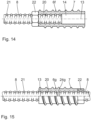
- the anchoring element 6g is used like the embodiment in FIG 9 for coupling two tension/compression elements 8.
- a structural element which is designed as a continuous partition wall, is arranged inside the bore 14 as the separating area 24g.
- the partition is also known as the center stop.
- the partition wall 24g is arranged approximately in the middle and in particular exactly in the middle.
- the partition wall 24g enables the anchoring element 6g to be detachably coupled to the two tension/compression elements 8, in particular by these being screwed into the internal thread and lying axially against the partition wall 24g.
- the anchoring unit comprising the tension/compression element 8 and the anchoring element 6h is also made in one piece, in that the two components are permanently coupled to one another.
- the anchoring element 6h has a continuous, cylindrical bore 14, with a threaded section AG and a press section A P being arranged one behind the other along the longitudinal axis 13.
- the cutting thread 7 is arranged in the threaded section A G .
- the cutting thread 7 is formed in one piece on the sleeve base body 12 .
- the anchoring unit according to 16 and 17 is particularly suitable as a ground anchor.
- the pressing section is designed without a thread, ie it has no additional components, in particular on its outer cylindrical surface.
- this pressing section A P the anchoring element 6h is mechanically pressed with the tension/compression element 8, ie joined by forming. It is advantageous if a tension/compression element 8 as a tension/compression element is used.
- the external coarse thread, ie the coupling thread 21 of the tension/compression element 8 forms undercut elements on the surface of the tension/compression element 8, which additionally increase the strength of the joint.
- the pressing section A P and the threaded section A G each extend to approximately 50% of the total length L tot of the anchoring element 6h.
- the pressing section A P and the threaded section AG are arranged in an overlapping manner along the longitudinal axis 13 at least in certain areas. This is expressed in particular by the fact that the cutting thread 7 is also implemented at least in regions in the pressing section A P .
- the anchoring element 6h is pressed with the tension/compression element 8, the cutting thread is impaired, in particular damaged and in particular destroyed.
- the production of the anchoring element 6h, in particular with the continuous bore 14, which has a constant inside diameter, is uncomplicated.
- the anchoring element can be produced, for example, as an extruded sleeve.
- the anchoring element 6i is in particular also designed as an extruded sleeve, but in a special configuration as an extruded reducing sleeve. This means that the inner diameter of the bore 14 is reduced in the pressing section A P .
- the inside diameter D i , G in the threaded section AG is larger than the inside diameter D i , P in the pressing section Ap.
- Di , G ⁇ 1.2 ⁇ D i,P in particular Di ,G ⁇ 1.5 ⁇ D i,P , in particular Di, G ⁇ 2.0 ⁇ D i ,P , in particular Di , G ⁇ 2.5 x Di , P and Di , G ⁇ 4 x Di , P .
- the anchoring element 6i can advantageously be pressed with the tension/compression element 8 since the wall thickness in the pressed section A P is increased. In this respect, more material is available for pressing. This simplifies the pressing process. The pressing force is reduced. The strength of the press connection is increased.
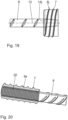
- the anchoring element 6j is designed to be particularly short.
- the anchoring element 6j has a ratio of the sleeve diameter D H to the overall length L ges that is less than 1, in particular less than 0.8, in particular less than 0.7, in particular less than 0.6, in particular less than 0.5, in particular less than 0.3 and in particular greater than or equal to 0.2.
- the tension/compression element 8 is conical, at least in sections.
- the bore 14j in the anchoring element 6j is conical, at least in sections.
- the anchoring unit according to 20 is made in one piece in that the anchoring element 6k is non-detachably coupled at the end face to the tension/compression element 8, in particular by welding.
- the anchoring element 6k has a sleeve base 16, which simplifies welding on the face side.
- the anchoring element 6k has a coupling section 20 in the form of a fine thread.
- the coupling section 20 is used, for example, to couple a coupling element 22e to the threaded coupling section 29 or another push/pull element which has a coupling thread in the form of a metric thread or a fine thread.
- the borehole 3 l is designed as a stepped bore.
- the stepped bore 3 1 has an inner bore hole section AB ,i and an outer bore hole section AB,a , which is arranged facing the upper side 4 of the material 2 .
- the inner borehole section AB,i has a first diameter D 1 and a first length l 1 .
- the outer borehole section AB,a has a second length l 2 and a second diameter D 2 .
- the sum of the lengths l 1 and l 2 gives the total borehole depth T B .
- the first diameter D 1 is smaller than the second diameter D 2 , in particular D 2 >D 1 , in particular D 2 ⁇ 1.2 ⁇ D 1 , in particular D 2 ⁇ 1.5 ⁇ D 1 , in particular D 2 ⁇ 1 .8 ⁇ D 1 , in particular D 2 ⁇ 2.0 ⁇ D 1 , in particular D 2 ⁇ 2.5 ⁇ D 1 , and in particular D 2 ⁇ 5 ⁇ D 1 .
- the respective cutting thread 7 on the anchoring elements 6, 9 has a cutting thread outer diameter which is slightly larger than the respective corresponding drill hole diameter D 1 , D 2 .
- the introduction and anchoring of the first anchoring element 6 is simplified.
- the first anchoring element 6 can be introduced essentially without contact and in particular without resistance along the outer borehole section AB ,a . It is only necessary to apply a screwing torque when the anchoring element 6 is screwed into the inner borehole section AB,i .
- the anchoring element 6 is formed in one piece on the tension/compression element 8 , ie is permanently connected to the tension/compression element 8 .
- a transition section 30 is formed on the tension/compression element 8, along which the rod diameter increases to the diameter of the anchoring element 6, in particular continuously.
- the anchoring element 6 can also be manufactured separately and subsequently coupled to the tension/compression element 8 .
- the tension/compression element 8 has a coupling thread 21 which is used for coupling to the second anchoring element 9 .
- the coupling thread 21 can be a coarse thread, a metric thread or a fine thread.
- the second anchoring element 9 can be used together with the tension/compression element 8 or subsequently introduced into the borehole 3 l .
- the second anchoring element 9 is flush with the surface, ie flush with the top 4 of the borehole 31 . It is also conceivable that the anchoring arrangement 11 is offset inwards in the borehole 31 .
- the tension/compression element 8 protrudes from the borehole 31 on the upper side 4 of the material 2.
- the exemplary embodiment differs from the previous exemplary embodiment essentially in that the anchoring element 6 is releasably coupled to the tension/compression element 8 and is additionally held as a coupling element 22 by means of a lock nut.
- the borehole 3m is designed as a stepped bore.
- the anchoring arrangement 1m is arranged on the inside in the stepped bore 3m, ie arranged set back in relation to the upper side 4 of the material 2.
- the second anchoring element 9 is held on the tension/compression element 8 by means of a further coupling element 22 in the form of a lock nut.
- a support disk 31 is provided between this lock nut 22 and the second anchoring element 9 for support.
- the two coupling elements 22 each have an internal thread that corresponds to the coupling thread 21 of the push/pull element.
- An outer diameter of the support disk 31 is in particular slightly smaller than the second diameter D 2 . This simplifies the insertion and placement of the support disk 31 on the tension/compression element 8 and in particular is possible without contact with the inner wall of the borehole 3m, in particular in the outer borehole section AB ,a .
- the second anchoring element 10n is arranged on the outside.
- the second anchoring element 10n is designed as an anchoring disk with an internal thread.
- the internal thread corresponds in particular to the external thread of the tension/compression element 8.
- the external thread is in particular an external coarse thread, but could also be designed as an external fine thread.
- the anchoring disk 10n can have a torque transmission section, not shown in detail, which can be implemented, for example, by a transverse slot, at least one groove and/or depressions or holes, which are arranged in particular eccentrically with respect to the longitudinal axis 5 of the borehole are.
- the anchor disk 10n can have a round outer contour. It is also conceivable for the outer contour to be non-round, in particular polygonal, for example in the form of a regular square or hexagon.
- the second anchoring element 10n is arranged set back on the material 2, in particular in relation to the upper side 4.
- a depression 33 is arranged in the material 2 on the upper side 4 .
- the depression 33 is in particular oriented concentrically to the borehole longitudinal axis 5 and is in particular of cylindrical design.
- the depression 33 extends in depth along the longitudinal axis 5 of the borehole in such a way that the push/pull element 8 does not protrude in relation to the upper side 4 .
- the use of backfill material 32 is optional.
- a plastic resin, in particular epoxy resin, is used in particular as the filling material.
- a mortar with polypropylene particles, in particular with polypropylene fibers, can also be used as filling material 32 .
- Such a plastic-reinforced mortar has advantageous fire protection properties.
Landscapes
- Engineering & Computer Science (AREA)
- General Engineering & Computer Science (AREA)
- Mechanical Engineering (AREA)
- Joining Of Building Structures In Genera (AREA)
Applications Claiming Priority (1)
| Application Number | Priority Date | Filing Date | Title |
|---|---|---|---|
| DE102022200439.6A DE102022200439A1 (de) | 2022-01-17 | 2022-01-17 | Verankerungselement zum Verankern in einem Bohrloch, Verankerungsanordnung mit einem derartigen Verankerungselement und Verfahren zum Herstellen einer derartigen Verankerungsanordnung |
Publications (1)
| Publication Number | Publication Date |
|---|---|
| EP4212743A1 true EP4212743A1 (fr) | 2023-07-19 |
Family
ID=84799927
Family Applications (1)
| Application Number | Title | Priority Date | Filing Date |
|---|---|---|---|
| EP23150083.6A Pending EP4212743A1 (fr) | 2022-01-17 | 2023-01-03 | Élément d'ancrage destiné à être ancré dans un puits de forage, ensemble d'ancrage comprenant un tel élément d'ancrage et procédé de fabrication d'un tel ensemble d'ancrage |
Country Status (2)
| Country | Link |
|---|---|
| EP (1) | EP4212743A1 (fr) |
| DE (1) | DE102022200439A1 (fr) |
Citations (3)
| Publication number | Priority date | Publication date | Assignee | Title |
|---|---|---|---|---|
| DE102011001176A1 (de) * | 2011-03-09 | 2012-09-13 | Rampa Verbindungstechnik GmbH & Co. KG | Gewindehülse |
| DE102016125201A1 (de) * | 2016-12-21 | 2018-06-21 | Ludwig Hettich Holding Gmbh & Co. Kg | System zum Fügen oder Armieren von Bauteilen |
| EP3388597A1 (fr) * | 2017-04-13 | 2018-10-17 | F.J. Aschwanden AG | Élément de renfort destiné à renforcer des plaques bétonnées |
-
2022
- 2022-01-17 DE DE102022200439.6A patent/DE102022200439A1/de active Pending
-
2023
- 2023-01-03 EP EP23150083.6A patent/EP4212743A1/fr active Pending
Patent Citations (3)
| Publication number | Priority date | Publication date | Assignee | Title |
|---|---|---|---|---|
| DE102011001176A1 (de) * | 2011-03-09 | 2012-09-13 | Rampa Verbindungstechnik GmbH & Co. KG | Gewindehülse |
| DE102016125201A1 (de) * | 2016-12-21 | 2018-06-21 | Ludwig Hettich Holding Gmbh & Co. Kg | System zum Fügen oder Armieren von Bauteilen |
| EP3388597A1 (fr) * | 2017-04-13 | 2018-10-17 | F.J. Aschwanden AG | Élément de renfort destiné à renforcer des plaques bétonnées |
Also Published As
| Publication number | Publication date |
|---|---|
| DE102022200439A1 (de) | 2023-07-20 |
Similar Documents
| Publication | Publication Date | Title |
|---|---|---|
| DE102010043769B4 (de) | Ankerbaugruppe, insbesondere für den Berg- und Tunnelbau | |
| EP3559484B1 (fr) | Système d'assemblage ou de blindage de composants | |
| EP3044468B1 (fr) | Hélice pour insert fileté | |
| WO2009109474A1 (fr) | Fondation forée | |
| DE3035867A1 (de) | Selbstverstopfender blindniet | |
| DE10341401B4 (de) | Verbundeinrichtung für eine Holz-Beton-Verbindung | |
| EP3219442B1 (fr) | Élement d'entrainement d'un couple de rotation sur une cosse a insert filete | |
| DE102007023735A1 (de) | Gewindenschneidende Betonschraube und Anordnung mit einer solchen Betonschraube | |
| EP0391119B1 (fr) | Elément de connexion pour un raccord vissé de boulons d'ancrage à injection auto-forants | |
| WO2002103212A1 (fr) | Tige d'ancrage | |
| DE202008003381U1 (de) | Ankermutter für ein Zugglied sowie Anker | |
| DE10311471A1 (de) | Gewindeformende Schraube für Untergründe aus harten Vollbaustoffen | |
| EP0262444B1 (fr) | Dispositif d'ancrage, notamment cheville | |
| WO2011020696A2 (fr) | Accouplement destiné à raccorder des éléments d'ancrage | |
| EP4212743A1 (fr) | Élément d'ancrage destiné à être ancré dans un puits de forage, ensemble d'ancrage comprenant un tel élément d'ancrage et procédé de fabrication d'un tel ensemble d'ancrage | |
| DE102010043765B4 (de) | Ankerbaugruppe sowie Verfahren zur Herstellung einer Ankerbaugruppe | |
| EP0908634B1 (fr) | Cheville à enfoncer | |
| EP1533471B1 (fr) | Boulon d'ancrage déformable | |
| EP4212744A1 (fr) | Unité d'ancrage pour ancrage dans un puits de forage dans un matériau, ensemble d'ancrage comprenant une telle unité d'ancrage et procédé de fabrication d'un tel ensemble d'ancrage | |
| EP3936670A1 (fr) | Pieu en béton et procédé d'accouplement de deux pieux en béton | |
| EP3880422A1 (fr) | Système de fixation d'un ancrage dans un substrat minéral | |
| DE4233304A1 (de) | Kupplungsmuffe und Verfahren zur Herstellung einer Kupplungsmuffe | |
| EP1457619A1 (fr) | Elément d'armature pour constructions en béton | |
| EP1213494B1 (fr) | Elément de fixation | |
| EP4166797A1 (fr) | Dispositif d'ancrage et procédé d'ancrage d'un élément d'ancrage dans un matériau |
Legal Events
| Date | Code | Title | Description |
|---|---|---|---|
| PUAI | Public reference made under article 153(3) epc to a published international application that has entered the european phase |
Free format text: ORIGINAL CODE: 0009012 |
|
| STAA | Information on the status of an ep patent application or granted ep patent |
Free format text: STATUS: THE APPLICATION HAS BEEN PUBLISHED |
|
| AK | Designated contracting states |
Kind code of ref document: A1 Designated state(s): AL AT BE BG CH CY CZ DE DK EE ES FI FR GB GR HR HU IE IS IT LI LT LU LV MC ME MK MT NL NO PL PT RO RS SE SI SK SM TR |
|
| STAA | Information on the status of an ep patent application or granted ep patent |
Free format text: STATUS: REQUEST FOR EXAMINATION WAS MADE |
|
| 17P | Request for examination filed |
Effective date: 20240111 |
|
| RBV | Designated contracting states (corrected) |
Designated state(s): AL AT BE BG CH CY CZ DE DK EE ES FI FR GB GR HR HU IE IS IT LI LT LU LV MC ME MK MT NL NO PL PT RO RS SE SI SK SM TR |