EP4212535A1 - Compound and organic light-emitting element comprising same - Google Patents
Compound and organic light-emitting element comprising same Download PDFInfo
- Publication number
- EP4212535A1 EP4212535A1 EP22864835.8A EP22864835A EP4212535A1 EP 4212535 A1 EP4212535 A1 EP 4212535A1 EP 22864835 A EP22864835 A EP 22864835A EP 4212535 A1 EP4212535 A1 EP 4212535A1
- Authority
- EP
- European Patent Office
- Prior art keywords
- group
- compound
- light emitting
- present specification
- substituted
- Prior art date
- Legal status (The legal status is an assumption and is not a legal conclusion. Google has not performed a legal analysis and makes no representation as to the accuracy of the status listed.)
- Granted
Links
Images

Classifications
-
- C—CHEMISTRY; METALLURGY
- C07—ORGANIC CHEMISTRY
- C07D—HETEROCYCLIC COMPOUNDS
- C07D493/00—Heterocyclic compounds containing oxygen atoms as the only ring hetero atoms in the condensed system
- C07D493/02—Heterocyclic compounds containing oxygen atoms as the only ring hetero atoms in the condensed system in which the condensed system contains two hetero rings
- C07D493/04—Ortho-condensed systems
-
- C—CHEMISTRY; METALLURGY
- C07—ORGANIC CHEMISTRY
- C07D—HETEROCYCLIC COMPOUNDS
- C07D407/00—Heterocyclic compounds containing two or more hetero rings, at least one ring having oxygen atoms as the only ring hetero atoms, not provided for by group C07D405/00
- C07D407/02—Heterocyclic compounds containing two or more hetero rings, at least one ring having oxygen atoms as the only ring hetero atoms, not provided for by group C07D405/00 containing two hetero rings
- C07D407/04—Heterocyclic compounds containing two or more hetero rings, at least one ring having oxygen atoms as the only ring hetero atoms, not provided for by group C07D405/00 containing two hetero rings directly linked by a ring-member-to-ring-member bond
-
- C—CHEMISTRY; METALLURGY
- C07—ORGANIC CHEMISTRY
- C07B—GENERAL METHODS OF ORGANIC CHEMISTRY; APPARATUS THEREFOR
- C07B59/00—Introduction of isotopes of elements into organic compounds ; Labelled organic compounds per se
- C07B59/002—Heterocyclic compounds
-
- C—CHEMISTRY; METALLURGY
- C09—DYES; PAINTS; POLISHES; NATURAL RESINS; ADHESIVES; COMPOSITIONS NOT OTHERWISE PROVIDED FOR; APPLICATIONS OF MATERIALS NOT OTHERWISE PROVIDED FOR
- C09K—MATERIALS FOR MISCELLANEOUS APPLICATIONS, NOT PROVIDED FOR ELSEWHERE
- C09K11/00—Luminescent materials, e.g. electroluminescent or chemiluminescent
- C09K11/02—Use of particular materials as binders, particle coatings or suspension media therefor
-
- C—CHEMISTRY; METALLURGY
- C09—DYES; PAINTS; POLISHES; NATURAL RESINS; ADHESIVES; COMPOSITIONS NOT OTHERWISE PROVIDED FOR; APPLICATIONS OF MATERIALS NOT OTHERWISE PROVIDED FOR
- C09K—MATERIALS FOR MISCELLANEOUS APPLICATIONS, NOT PROVIDED FOR ELSEWHERE
- C09K11/00—Luminescent materials, e.g. electroluminescent or chemiluminescent
- C09K11/06—Luminescent materials, e.g. electroluminescent or chemiluminescent containing organic luminescent materials
-
- H—ELECTRICITY
- H10—SEMICONDUCTOR DEVICES; ELECTRIC SOLID-STATE DEVICES NOT OTHERWISE PROVIDED FOR
- H10K—ORGANIC ELECTRIC SOLID-STATE DEVICES
- H10K50/00—Organic light-emitting devices
- H10K50/10—OLEDs or polymer light-emitting diodes [PLED]
- H10K50/11—OLEDs or polymer light-emitting diodes [PLED] characterised by the electroluminescent [EL] layers
- H10K50/12—OLEDs or polymer light-emitting diodes [PLED] characterised by the electroluminescent [EL] layers comprising dopants
-
- H—ELECTRICITY
- H10—SEMICONDUCTOR DEVICES; ELECTRIC SOLID-STATE DEVICES NOT OTHERWISE PROVIDED FOR
- H10K—ORGANIC ELECTRIC SOLID-STATE DEVICES
- H10K85/00—Organic materials used in the body or electrodes of devices covered by this subclass
- H10K85/60—Organic compounds having low molecular weight
- H10K85/615—Polycyclic condensed aromatic hydrocarbons, e.g. anthracene
-
- H—ELECTRICITY
- H10—SEMICONDUCTOR DEVICES; ELECTRIC SOLID-STATE DEVICES NOT OTHERWISE PROVIDED FOR
- H10K—ORGANIC ELECTRIC SOLID-STATE DEVICES
- H10K85/00—Organic materials used in the body or electrodes of devices covered by this subclass
- H10K85/60—Organic compounds having low molecular weight
- H10K85/631—Amine compounds having at least two aryl rest on at least one amine-nitrogen atom, e.g. triphenylamine
-
- H—ELECTRICITY
- H10—SEMICONDUCTOR DEVICES; ELECTRIC SOLID-STATE DEVICES NOT OTHERWISE PROVIDED FOR
- H10K—ORGANIC ELECTRIC SOLID-STATE DEVICES
- H10K85/00—Organic materials used in the body or electrodes of devices covered by this subclass
- H10K85/60—Organic compounds having low molecular weight
- H10K85/649—Aromatic compounds comprising a hetero atom
- H10K85/654—Aromatic compounds comprising a hetero atom comprising only nitrogen as heteroatom
-
- H—ELECTRICITY
- H10—SEMICONDUCTOR DEVICES; ELECTRIC SOLID-STATE DEVICES NOT OTHERWISE PROVIDED FOR
- H10K—ORGANIC ELECTRIC SOLID-STATE DEVICES
- H10K85/00—Organic materials used in the body or electrodes of devices covered by this subclass
- H10K85/60—Organic compounds having low molecular weight
- H10K85/649—Aromatic compounds comprising a hetero atom
- H10K85/657—Polycyclic condensed heteroaromatic hydrocarbons
-
- H—ELECTRICITY
- H10—SEMICONDUCTOR DEVICES; ELECTRIC SOLID-STATE DEVICES NOT OTHERWISE PROVIDED FOR
- H10K—ORGANIC ELECTRIC SOLID-STATE DEVICES
- H10K85/00—Organic materials used in the body or electrodes of devices covered by this subclass
- H10K85/60—Organic compounds having low molecular weight
- H10K85/649—Aromatic compounds comprising a hetero atom
- H10K85/657—Polycyclic condensed heteroaromatic hydrocarbons
- H10K85/6572—Polycyclic condensed heteroaromatic hydrocarbons comprising only nitrogen in the heteroaromatic polycondensed ring system, e.g. phenanthroline or carbazole
-
- H—ELECTRICITY
- H10—SEMICONDUCTOR DEVICES; ELECTRIC SOLID-STATE DEVICES NOT OTHERWISE PROVIDED FOR
- H10K—ORGANIC ELECTRIC SOLID-STATE DEVICES
- H10K85/00—Organic materials used in the body or electrodes of devices covered by this subclass
- H10K85/60—Organic compounds having low molecular weight
- H10K85/649—Aromatic compounds comprising a hetero atom
- H10K85/657—Polycyclic condensed heteroaromatic hydrocarbons
- H10K85/6574—Polycyclic condensed heteroaromatic hydrocarbons comprising only oxygen in the heteroaromatic polycondensed ring system, e.g. cumarine dyes
-
- C—CHEMISTRY; METALLURGY
- C07—ORGANIC CHEMISTRY
- C07B—GENERAL METHODS OF ORGANIC CHEMISTRY; APPARATUS THEREFOR
- C07B2200/00—Indexing scheme relating to specific properties of organic compounds
- C07B2200/05—Isotopically modified compounds, e.g. labelled
-
- H—ELECTRICITY
- H10—SEMICONDUCTOR DEVICES; ELECTRIC SOLID-STATE DEVICES NOT OTHERWISE PROVIDED FOR
- H10K—ORGANIC ELECTRIC SOLID-STATE DEVICES
- H10K50/00—Organic light-emitting devices
- H10K50/10—OLEDs or polymer light-emitting diodes [PLED]
- H10K50/11—OLEDs or polymer light-emitting diodes [PLED] characterised by the electroluminescent [EL] layers
Definitions
- the present specification relates to a compound and an organic light emitting device including the same.
- an organic light emitting phenomenon refers to a phenomenon in which electric energy is converted into light energy by using an organic material.
- An organic light emitting device using the organic light emitting phenomenon usually has a structure including a positive electrode, a negative electrode, and an organic material layer interposed therebetween.
- the organic material layer may have a multi-layered structure composed of different materials in many cases in order to improve the efficiency and stability of the organic light emitting device, and may be composed of, for example, a hole injection layer, a hole transport layer, a light emitting layer, an electron transport layer, an electron injection layer, and the like.
- the present specification provides a compound and an organic light emitting device including the same.
- An exemplary embodiment of the present specification provides a compound represented by the following Chemical Formula 1.
- an organic light emitting device including: a first electrode; a second electrode; and an organic material layer having one or more layers provided between the first electrode and the second electrode, in which one or more layers of the organic material layer include the compound.
- the compound described in the present specification can be used as a material for an organic material layer of an organic light emitting device.
- the compound according to another exemplary embodiment can improve the efficiency, achieve low driving voltage and/or improve lifetime characteristics in the organic light emitting device.
- FIGS. 1 and 2 illustrate an example of an organic light emitting device according to an exemplary embodiment of the present specification.
- An exemplary embodiment of the present specification provides the compound represented by Chemical Formula 1.
- Chemical formula 1 includes 1) Ar1 and 2) L1 bound to position 3 of benzobisbenzofuran as substituents at an anthracene core, and has a structure in which at least one hydrogen at a substitutable position of the anthracene of Chemical Formula 1 is substituted with deuterium, there are structural characteristics that the mobility of electrons and holes is improved and the molecular stability is improved. Therefore, an organic light emitting device including the same are excellent in terms of driving voltage, efficiency and service life.
- the term "combination thereof" included in the Markush type expression means a mixture or combination of one or more selected from the group consisting of constituent elements described in the Markush type expression, and means including one or more selected from the group consisting of the above-described constituent elements.
- substitution means that a hydrogen atom bonded to a carbon atom of a compound is changed into another substituent, and a position to be substituted is not limited as long as the position is a position at which the hydrogen atom is substituted, that is, a position at which the substituent may be substituted, and when two or more are substituted, the two or more substituents may be the same as or different from each other.
- substituted or unsubstituted means being substituted with one or more substituents selected from the group consisting of deuterium; a halogen group; a hydroxyl group; a cyano group; a nitro group; an alkyl group; a cycloalkyl group; an alkoxy group; an alkenyl group; a haloalkyl group; a silyl group; a boron group; an amine group; an aryl group; and a heteroaryl group, being substituted with a substituent to which two or more substituents among the exemplified substituents are linked, or having no substituent.
- the fact that two or more substituents are linked indicates that hydrogen of any one substituent is linked to another substituent.
- a phenyl group and a naphthyl group may be linked to each other to become a substituent of or
- the case where three substituents are linked to one another includes not only a case where (Substituent 1)-(Substituent 2)-(Substituent 3) are consecutively linked to one another, but also a case where (Substituent 2) and (Substituent 3) are linked to (Substituent 1).
- a phenyl group, a naphthyl group, and an isopropyl group may be linked to one another to form a substituent of or
- the above-described definition also applies equally to the case where four or more substituents are linked to one another.
- examples of a halogen group include fluorine, chlorine, bromine or iodine.
- the alkyl group may be straight-chained or branched, and the number of carbon atoms thereof is not particularly limited, but is preferably 1 to 30.
- Specific examples thereof include methyl, ethyl, propyl, n-propyl, isopropyl, butyl, n-butyl, isobutyl, tert-butyl, sec-butyl, 1-methyl-butyl, 1-ethylbutyl, pentyl, n-pentyl, isopentyl, neopentyl, tert-pentyl, hexyl, n-hexyl, 1-methylpentyl, 2-methylpentyl, 4-methyl-2-pentyl, 3,3-dimethylbutyl, 2-ethylbutyl, heptyl, n-heptyl, 1-methylhexyl, cyclopentylmethyl, cyclohexylmethyl, oct
- a cycloalkyl group is not particularly limited, but has preferably 3 to 30 carbon atoms, and specific examples thereof include cyclopropyl, cyclobutyl, cyclopentyl, 3-methylcyclopentyl, 2,3-dimethylcyclopentyl, cyclohexyl, 3-methylcyclohexyl, 4-methylcyclohexyl, 2,3-dimethylcyclohexyl, 3,4,5-trimethylcyclohexyl, 4-tert-butylcyclohexyl, cycloheptyl, cyclooctyl, an adamantyl group, and the like, but are not limited thereto.
- the alkoxy group may be straight-chained, branched, or cyclic.
- the number of carbon atoms of the alkoxy group is not particularly limited, but is preferably 1 to 30. Specific examples thereof include methoxy, ethoxy, n-propoxy, isopropoxy, n-butoxy, isobutoxy, tert-butoxy, sec-butoxy, n-pentyloxy, neopentyloxy, isopentyloxy, n-hexyloxy, 3,3-dimethylbutyloxy, 2-ethylbutyloxy, n-octyloxy, n-nonyloxy, n-decyloxy, benzyloxy, p-methylbenzyloxy, and the like, but are not limited thereto.
- the alkenyl group may be straight-chained or branched, and the number of carbon atoms thereof is not particularly limited, but is preferably 2 to 30.
- Specific examples thereof include vinyl, 1-propenyl, isopropenyl, 1-butenyl, 2-butenyl, 3-butenyl, 1-pentenyl, 2-pentenyl, 3-pentenyl, 3-methyl-1-butenyl, 1,3-butadienyl, allyl, 1-phenylvinyl-1-yl, 2-phenylvinyl-1-yl, 2,2-diphenylvinyl-1-yl, 2-phenyl-2-(naphthyl-1-yl)vinyl-1-yl, 2,2-bis(diphenyl-1-yl)vinyl-1-yl, a stilbenyl group, a styrenyl group, and the like, but are not limited thereto.
- haloalkyl group means that at least one halogen group is substituted instead of hydrogen in an alkyl group in the definition of the alkyl group.
- an aryl group is not particularly limited, but has preferably 6 to 30 carbon atoms, and the aryl group may be monocyclic or polycyclic.
- the aryl group is a monocyclic aryl group
- the number of carbon atoms thereof is not particularly limited, but is preferably 6 to 30.
- Specific examples of the monocyclic aryl group include a phenyl group, a biphenyl group, a terphenyl group, and the like, but are not limited thereto.
- the aryl group is a polycyclic aryl group
- the number of carbon atoms thereof is not particularly limited, but is preferably 10 to 30.
- Specific examples of the polycyclic aryl group include a naphthyl group, an anthracene group, a phenanthrene group, a triphenylene group, a pyrene group, a phenalene group, a perylene group, a chrysene group, a fluorene group, and the like, but are not limited thereto.
- the fluorene group may be substituted, and adjacent groups may be bonded to each other to form a ring.
- fluorene group examples include and the like, but are not limited thereto.
- the "adjacent" group may mean a substituent substituted with an atom directly linked to an atom in which the corresponding substituent is substituted, a substituent disposed to be sterically closest to the corresponding substituent, or another substituent substituted with an atom in which the corresponding substituent is substituted.
- two substituents substituted at the ortho position in a benzene ring and two substituents substituted with the same carbon in an aliphatic ring may be interpreted as groups which are "adjacent" to each other.
- a heteroaryl group includes one or more atoms other than carbon, that is, one or more heteroatoms, and specifically, the heteroatom may include one or more atoms selected from the group consisting of O, N, Se, S, and the like.
- the number of carbon atoms thereof is not particularly limited, but is preferably 2 to 30, and the heteroaryl group may be monocyclic or polycyclic.
- heteroaryl group examples include a thiophene group, a furan group, a pyrrole group, an imidazole group, a thiazole group, an oxazole group, an oxadiazole group, a pyridine group, a bipyridine group, a pyrimidine group, a triazine group, a triazole group, an acridine group, a pyridazine group, a pyrazine group, a quinoline group, a quinazoline group, a quinoxaline group, a phthalazine group, a pyridopyrimidine group, a pyridopyrazine group, a pyrazinopyrazine group, an isoquinoline group, an indole group, a carbazole group, a benzoxazole group, a benzimidazole group, a benzothiazole group, a benzocarbazole
- the silyl group may be an alkylsilyl group, an arylsilyl group, a heteroarylsilyl group, and the like.
- the above-described examples of the alkyl group may be applied to the alkyl group in the alkylsilyl group
- the above-described examples of the aryl group may be applied to the aryl group in the arylsilyl group
- the examples of the heteroaryl group may be applied to the heteroaryl group in the heteroarylsilyl group.
- a boron group may be - BR 100 R 101 , and R 100 and R 101 are the same as or different from each other, and may be each independently selected from the group consisting of hydrogen; deuterium; halogen; a nitrile group; a substituted or unsubstituted monocyclic or polycyclic cycloalkyl group having 3 to 30 carbon atoms; a substituted or unsubstituted straight-chained or branched alkyl group having 1 to 30 carbon atoms; a substituted or unsubstituted monocyclic or polycyclic aryl group having 6 to 30 carbon atoms; and a substituted or unsubstituted monocyclic or polycyclic heteroaryl group having 2 to 30 carbon atoms.
- Specific examples of the boron group include a dimethylboron group, a diethylboron group, a t-butylmethylboron group, a diphenylboron group, and the like, but are not
- an amine group may be selected from the group consisting of -NH 2 , an alkylamine group, an N-alkylarylamine group, an arylamine group, an N-arylheteroarylamine group, an N-alkylheteroarylamine group, and a heteroarylamine group, and the number of carbon atoms thereof is not particularly limited, but is preferably 1 to 30.
- the amine group include a methylamine group, a dimethylamine group, an ethylamine group, a diethylamine group, a phenylamine group, a naphthylamine group, a biphenylamine group, an anthracenylamine group, a 9-methyl-anthracenylamine group, a diphenylamine group, a ditolylamine group, an N-phenyltolylamine group, an N-phenylbiphenylamine group, an N-phenylnaphthylamine group, an N-biphenylnaphthylamine group, an N-naphthylfluorenylamine group, an N-phenylphenanthrenylamine group, an N-biphenylphenanthrenylamine group, an N-phenylfluorenylamine group, an N-phenyl terphenylamine group, an N-phenanthrenylamine group
- an N-alkylarylamine group means an amine group in which an alkyl group and an aryl group are substituted with N of the amine group.
- the alkyl group and the aryl group in the N-alkylarylamine group are the same as the above-described examples of the alkyl group and the aryl group.
- an N-arylheteroarylamine group means an amine group in which an aryl group and a heteroaryl group are substituted with N of the amine group.
- the aryl group and heteroaryl group in the N-arylheteroarylamine group are the same as the above-described examples of the aryl group and the heteroaryl group.
- an N-alkylheteroarylamine group means an amine group in which an alkyl group and a heteroaryl group are substituted with N of the amine group.
- the alkyl group and the heteroaryl group in the N-alkylheteroarylamine group are the same as the above-described examples of the alkyl group and the heteroaryl group.
- examples of an alkylamine group include a substituted or unsubstituted monoalkylamine group or a substituted or unsubstituted dialkylamine group.
- the alkyl group in the alkylamine group may be a straight-chained or branched alkyl group.
- the alkylamine group including two or more alkyl groups may include a straight-chained alkyl group, a branched alkyl group, or both a straight-chained alkyl group and a branched alkyl group.
- the alkyl group in the alkylamine group may be selected from the above-described examples of the alkyl group.
- examples of an arylamine group include a substituted or unsubstituted monoarylamine group or a substituted or unsubstituted diarylamine group.
- the aryl group in the arylamine group may be a monocyclic aryl group or a polycyclic aryl group.
- the arylamine group including two or more aryl groups may include a monocyclic aryl group, a polycyclic aryl group, or both a monocyclic aryl group and a polycyclic aryl group.
- the aryl group in the arylamine group may be selected from the above-described examples of the aryl group.
- examples of a heteroarylamine group include a substituted or unsubstituted monoheteroarylamine group or a substituted or unsubstituted diheteroarylamine group.
- the heteroarylamine group including two or more heteroaryl groups may include a monocyclic heteroaryl group, a polycyclic heteroaryl group, or both a monocyclic heteroaryl group and a polycyclic heteroaryl group.
- the heteroaryl group in the heteroarylamine group may be selected from the above-described examples of the heteroaryl group.
- an arylene group means a group having two bonding positions in an aryl group, that is, a divalent group.
- the above-described description on the aryl group may be applied to the arylene group, except that the arylene groups are each a divalent group.
- deuteration or “deuterated” means that hydrogen at a substitutable position of a compound is substituted with deuterium.
- overdeuterated means a compound or group in which all hydrogens in the molecule are substituted with deuterium, and has the same meaning as "100% deuterated”.
- X% deuterated means that X% of the hydrogens at substitutable positions in the corresponding structure are substituted with deuterium.
- the dibenzofuran being “25% deuterated”, “25% degree of deuteration” of the dibenzofuran, or “25% deuterium substitution rate” of the dibenzofuran means that 2 of the 8 hydrogens at the substitutable positions of the dibenzofuran are substituted with deuterium.
- the degree of deuteration may be confirmed by a known method such as nuclear magnetic resonance spectroscopy ( 1 H NMR), thin-layer chromatography/mass spectrometry (TLC/MS), or matrix assisted laser desorption/ionization time-of-flight mass spectrometry (MALDI-TOF MS).
- 1 H NMR nuclear magnetic resonance spectroscopy
- TLC/MS thin-layer chromatography/mass spectrometry
- MALDI-TOF MS matrix assisted laser desorption/ionization time-of-flight mass spectrometry
- Chemical Formula 1 is represented by the following Chemical Formula 1-1 or 1-2.
- Chemical Formula 1 is represented by the following Chemical Formula 1-3 or 1-4.
- 0 in the definitions of a2 to a4 means that hydrogen is bound instead of deuterium.
- a2 is an integer from 1 to 4.
- a2 is 0.
- a2 is 1.
- a2 is 2.
- a2 is 3.
- a2 is 4.
- a3 is an integer from 1 to 4.
- a3 is 0.
- a3 is 1.
- a3 is 2.
- a3 is 3.
- a3 is 4.
- a4 is an integer from 1 to 4.
- a4 is 0.
- a4 is 1.
- a4 is 2.
- a4 is 3.
- a4 is 4.
- a1 is 1.
- a1 is 2.
- a1 is 3.
- a1 is 4.
- a1 is 5.
- a1 is 6.
- a1 is 7.
- a1 is 8.
- At least one of R1 to R9 is deuterium, and the others are hydrogen.
- one of R1 to R9 is deuterium, and the others are hydrogen.
- two of R1 to R9 are deuterium, and the others are hydrogen.
- three of R1 to R9 are deuterium, and the others are hydrogen.
- R1 to R9 are deuterium, and the others are hydrogen.
- R1 to R9 are deuterium, and the others are hydrogen.
- R1 to R9 are deuterium, and the others are hydrogen.
- seven of R1 to R9 are deuterium, and the others are hydrogen.
- водородани ⁇ ов eight of R1 to R9 are deuterium, and the other is hydrogen.
- R1 to R9 are deuterium.
- R1 to R9 are hydrogen.
- L1 is a direct bond; or a monocyclic or polycyclic arylene group having 6 to 30 carbon atoms, which is unsubstituted or substituted with deuterium
- Ar1 is a monocyclic or polycyclic aryl group having 6 to 30 carbon atoms, which is unsubstituted or substituted with one or more substituents of deuterium, a monocyclic or polycyclic aryl group having 6 to 30 carbon atoms, and a combination thereof.
- L1 is a direct bond; or a substituted or unsubstituted monocyclic or polycyclic arylene group having 6 to 30 carbon atoms.
- L1 is a direct bond; or a substituted or unsubstituted monocyclic or polycyclic arylene group having 6 to 20 carbon atoms.
- L1 is a direct bond; or a monocyclic or polycyclic arylene group having 6 to 30 carbon atoms, which is unsubstituted or substituted with deuterium.
- L1 is a direct bond; or a monocyclic or polycyclic arylene group having 6 to 20 carbon atoms, which is unsubstituted or substituted with deuterium.
- L1 is a direct bond; a phenylene group unsubstituted or substituted with deuterium; or a naphthylene group unsubstituted or substituted with deuterium.
- Ar1 is a substituted or unsubstituted monocyclic or polycyclic aryl group having 6 to 30 carbon atoms.
- Ar1 is a substituted or unsubstituted monocyclic or polycyclic aryl group having 6 to 20 carbon atoms.
- Ar1 is a monocyclic or polycyclic aryl group having 6 to 30 carbon atoms, which is unsubstituted or substituted with one or more substituents of deuterium, a monocyclic or polycyclic aryl group having 6 to 30 carbon atoms, and a combination thereof.
- Ar1 is a monocyclic or polycyclic aryl group having 6 to 20 carbon atoms, which is unsubstituted or substituted with one or more substituents of deuterium, a monocyclic or polycyclic aryl group having 6 to 20 carbon atoms, and a combination thereof.
- Ar1 is a phenyl group unsubstituted or substituted with one or more substituents of deuterium, a naphthyl group, and a combination; a biphenyl group unsubstituted or substituted with deuterium; or a naphthyl group unsubstituted or substituted with deuterium.
- Chemical Formula 1 is any one selected from the following compounds.
- the present specification provides an organic light emitting device including the above-described compound.
- the ⁇ layer' has a meaning compatible with a ⁇ film' usually used in the art, and means a coating covering a target region.
- the size of the ⁇ layer' is not limited, and the sizes of the respective 'layers' may be the same as or different from one another. According to an exemplary embodiment, the size of the ⁇ layer' may be the same as that of the entire device, may correspond to the size of a specific functional region, and may also be as small as a single sub-pixel.
- the present specification provides an organic light emitting device including: a first electrode; a second electrode; and an organic material layer having one or more layers provided between the first electrode and the second electrode, in which one or more layers of the organic material layer include the compound represented by Chemical Formula 1.
- the organic material layer of the organic light emitting device of the present specification may also be composed of a single-layered structure, but may be composed of a multi-layered structure in which two or more organic material layers are stacked.
- the organic material layer may have a structure including a hole injection layer, a hole transport layer, a light emitting layer, an electron transport layer, an electron injection layer, an electron blocking layer, a hole blocking layer, and the like.
- the structure of the organic light emitting device is not limited thereto, and may include a fewer number of organic layers.
- the organic material layer includes a hole injection layer, a hole transport layer, or an electron blocking layer, and the hole injection layer, the hole transport layer, or the electron blocking layer includes the compound.
- the organic material layer includes a light emitting layer, and the light emitting layer includes the compound.
- the organic material layer includes a light emitting layer, and the light emitting layer includes the compound as a host of the light emitting layer.
- the light emitting layer includes a dopant
- the dopant includes one or more selected from the group consisting of a fluorescent dopant, a phosphorescent dopant, and a thermally delayed fluorescent dopant.
- the fluorescent dopant includes one or more selected from the group consisting of an arylamine-based compound and a boron-based compound.
- the fluorescent dopant is an arylamine-based compound.
- the fluorescent dopant is a boron-based compound.
- the organic material layer includes a light emitting layer
- the light emitting layer includes a host and a dopant
- the host includes the compound
- the dopant includes one or more selected from the group consisting of the fluorescent dopant, the phosphorescent dopant, and the thermally delayed fluorescent dopant.
- the arylamine-based compound is represented by the following Chemical Formula D-1.
- L101 and L102 are a direct bond.
- Ar101 to Ar104 are the same as or different from each other, and are each independently a substituted or unsubstituted monocyclic or polycyclic aryl group having 6 to 30 carbon atoms; or a substituted or unsubstituted monocyclic or polycyclic heteroaryl group having 2 to 30 carbon atoms.
- Ar101 to Ar104 are the same as or different from each other, and are each independently a monocyclic or polycyclic aryl group having 6 to 30 carbon atoms, which is unsubstituted or substituted with a straight-chained or branched alkyl group having 1 to 30 carbon atoms; or a monocyclic or polycyclic heteroaryl group having 2 to 30 carbon atoms.
- Ar101 to Ar104 are the same as or different from each other, and are each independently a phenyl group substituted with a methyl group; or a dibenzofuran group.
- Chemical Formula D-1 is represented by the following compound.
- the boron-based compound is represented by the following Chemical Formula D-2.
- T1 to T5 are the same as or different from each other, and are each independently hydrogen; a substituted or unsubstituted straight-chained or branched alkyl group having 1 to 30 carbon atoms; a substituted or unsubstituted monocyclic or polycyclic arylamine group having 6 to 30 carbon atoms; or a substituted or unsubstituted monocyclic or polycyclic aryl group having 6 to 30 carbon atoms.
- T1 to T5 are the same as or different from each other, and are each independently hydrogen; a straight-chained or branched alkyl group having 1 to 30 carbon atoms; a monocyclic or polycyclic arylamine group having 6 to 30 carbon atoms; or a monocyclic or polycyclic aryl group having 6 to 30 carbon atoms, which is unsubstituted or substituted with a straight-chained or branched alkyl group having 1 to 30 carbon atoms.
- T1 to T5 are the same as or different from each other, and are each independently hydrogen; a tert-butyl group; a diphenylamine group; or a phenyl group unsubstituted or substituted with a tert-butyl group.
- Chemical Formula D-2 is represented by the following compound.
- the phosphorescent dopant and the thermally delayed fluorescent dopant those known in the art are used, but the phosphorescent dopant and the thermally delayed fluorescent dopant are not limited thereto.
- the light emitting layer includes the host and the dopant at a weight ratio of 99:1 to 1:99.
- the light emitting layer includes the host and the dopant specifically, at a weight ratio of 99:1 to 50:50, and more specifically, at a weight ratio of 99:1 to 95:5.
- the organic light emitting device further includes one or two or more layers selected from the group consisting of a hole injection layer, a hole transport layer, a light emitting layer, an electron transport layer, an electron injection layer, a hole blocking layer, and an electron blocking layer.
- the organic light emitting device includes: a first electrode; a second electrode; a light emitting layer provided between the first electrode and the second electrode; and an organic material layer having two or more layers provided between the light emitting layer and the first electrode, or between the light emitting layer and the second electrode.
- two or more may be selected from the group consisting of a light emitting layer, a hole transport layer, a hole injection layer, a hole injection and transport layer, an electron blocking layer, a hole blocking layer, an electron injection layer, an electron transport layer, and an electron injection and transport layer.
- a hole injection layer having two or more layers is included between the light emitting layer and the first electrode.
- the hole injection layer having two or more layers may include materials which are the same as or different from each other.
- a hole transport layer having two or more layers is included between the light emitting layer and the first electrode.
- the hole transport layer having two or more layers may include materials which are the same as or different from each other.
- an electron transport layer having two or more layers is included between the light emitting layer and the second electrode.
- the electron transport layer having two or more layers may include materials which are the same as or different from each other.
- the first electrode is an anode or a cathode.
- the second electrode is a cathode or an anode.
- the organic light emitting device may be a normal type organic light emitting device in which an anode, an organic material layer having one or more layers, and a cathode are sequentially stacked on a substrate.
- the organic light emitting device may be an inverted type organic light emitting device in which a cathode, an organic material layer having one or more layers, and an anode are sequentially stacked on a substrate.
- FIGS. 1 and 2 exemplify an organic light emitting device, and the organic light emitting device is not limited thereto.
- FIG. 1 exemplifies a structure of an organic light emitting device in which a first electrode 2, a light emitting layer 4, and a second electrode 3 are sequentially stacked on a substrate 1.
- the compound of Chemical Formula 1 is included in the light emitting layer 4.
- FIG. 2 exemplifies a structure of an organic light emitting device in which a substrate 1, a first electrode 2, a first hole injection layer 5, a second hole injection layer 6, a hole transport layer 7, an electron blocking layer 8, a light emitting layer 4, a first electron transport layer 9, a second electron transport layer 10, an electron injection layer 11, and a second electrode 3 are sequentially stacked.
- the compound may be included in the light emitting layer 4.
- the organic light emitting device of the present specification may be manufactured by the materials and methods known in the art, except that the light emitting layer includes the compound, that is, the compound represented by Chemical Formula 1.
- the organic material layers may be formed of the same material or different materials.
- the organic light emitting device of the present specification may be manufactured by sequentially stacking a first electrode, an organic material layer, and a second electrode on a substrate.
- the organic light emitting device may be manufactured by depositing a metal or a metal oxide having conductivity, or an alloy thereof on a substrate to form an anode, forming an organic material layer including a hole injection layer, a hole transport layer, a light emitting layer, and an electron transport layer thereon, and then depositing a material, which may be used as a cathode, thereon, by using a physical vapor deposition (PVD) method such as sputtering or e-beam evaporation.
- PVD physical vapor deposition
- an organic light emitting device may be manufactured by sequentially depositing a second electrode material, an organic material layer, and a first electrode material on a substrate.
- the compound represented by Chemical Formula 1 may be formed as an organic material layer by not only a vacuum deposition method, but also a solution application method when an organic light emitting device is manufactured.
- the solution application method means spin coating, dip coating, doctor blading, inkjet printing, screen printing, a spray method, roll coating, and the like, but is not limited thereto.
- an organic light emitting device may be made by sequentially depositing a second electrode material, an organic material layer, and a first electrode material on a substrate.
- the manufacturing method is not limited thereto.
- the first electrode material materials having a high work function are usually preferred so as to facilitate the injection of holes into an organic material layer.
- materials having a high work function include: a metal, such as vanadium, chromium, copper, zinc, and gold, or an alloy thereof; a metal oxide, such as zinc oxide, indium oxide, indium tin oxide (ITO), and indium zinc oxide (IZO); a combination of a metal and an oxide, such as ZnO:Al or SnO 2 :Sb; a conductive polymer, such as poly(3-methylthiophene), poly[3,4-(ethylene-1,2-dioxy)thiophene] (PEDOT), polypyrrole, and polyaniline; and the like, but are not limited thereto.
- a metal such as vanadium, chromium, copper, zinc, and gold, or an alloy thereof
- a metal oxide such as zinc oxide, indium oxide, indium tin oxide (ITO), and indium zinc oxide (IZO)
- the second electrode material materials having a low work function are usually preferred so as to facilitate the injection of electrons into an organic material layer.
- materials having a low work function include: a metal, such as magnesium, calcium, sodium, potassium, titanium, indium, yttrium, lithium, gadolinium, aluminum, silver, tin, and lead, or an alloy thereof; a multi-layer structured material, such as LiF/Al or LiO 2 /Al; and the like, but are not limited thereto.
- the light emitting layer may include a host material and a dopant material.
- a host material include a fused and/or non-fused aromatic ring derivative, a hetero ring-containing compound, or the like.
- fused aromatic ring derivative examples include anthracene derivatives, pyrene derivatives, naphthalene derivatives, pentacene derivatives, phenanthrene compounds, fluoranthene compounds, and the like
- hetero ring-containing compound examples include dibenzofuran derivatives, ladder-type furan compounds, pyrimidine derivatives, and the like, but the examples are not limited thereto.
- the dopant material examples include an aromatic amine derivative, a styrylamine compound, a boron complex, a fluoranthene compound, a metal complex, and the like.
- the aromatic amine derivative is a fused aromatic ring derivative having a substituted or unsubstituted arylamine group, and examples thereof include pyrene, anthracene, chrysene, periflanthene, and the like having an arylamine group.
- the styrylamine compound is a compound in which a substituted or unsubstituted arylamine is substituted with at least one arylvinyl group, and one or two or more substituents selected from the group consisting of an aryl group, a silyl group, an alkyl group, a cycloalkyl group, and an arylamine group are substituted or unsubstituted.
- substituents selected from the group consisting of an aryl group, a silyl group, an alkyl group, a cycloalkyl group, and an arylamine group are substituted or unsubstituted.
- Specific examples thereof include styrylamine, styryldiamine, styryltriamine, styryltetramine, and the like, but are not limited thereto.
- examples of the metal complex include an iridium complex, a platinum complex, and the like, but are not limited thereto.
- the hole injection layer is a layer which accepts holes from an electrode. It is preferred that hole injection material has an ability to transport holes, and has an effect of accepting holes from an anode and an excellent hole injection effect for a light emitting layer or a light emitting material. Further, the hole injection material is preferably a material which is excellent in ability to prevent excitons produced from a light emitting layer from moving to an electron injection layer or an electron injection material. In addition, the hole injection material is preferably a material which is excellent in ability to form a thin film. In addition, the highest occupied molecular orbital (HOMO) of the hole injection material is preferably a value between the work function of the anode material and the HOMO of the neighboring organic material layer.
- HOMO highest occupied molecular orbital
- the hole injection material include: metal porphyrin, oligothiophene, and arylamine-based organic materials; hexanitrile hexaazatriphenylene-based organic materials; quinacridone-based organic materials; perylene-based organic materials; polythiophene-based conductive polymers such as anthraquinone and polyaniline; and the like, but are not limited thereto.
- the hole injection layer includes a compound represented by the following Chemical Formula HI-1, but is not limited thereto.
- R301 to R304 are hydrogen.
- R300 is a substituted or unsubstituted aryl group.
- R300 is a monocyclic or polycyclic aryl group having 6 to 30 carbon atoms.
- R300 is a phenyl group.
- R300 is boned to R301 or R302 to form a substituted or unsubstituted ring.
- R300 is bonded to R301 or R302 to form an indole ring.
- R305 to R308 are the same as or different from each other, and are each independently a substituted or unsubstituted aryl group; or a substituted or unsubstituted heteroaryl group.
- R305 to R308 are the same as or different from each other, and are each independently a monocyclic or polycyclic aryl group having 6 to 30 carbon atoms; or a monocyclic or polycyclic heteroaryl group having 2 to 30 carbon atoms, which is unsubstituted or substituted with a monocyclic or polycyclic aryl group having 6 to 30 carbon atoms.
- R305 to R308 are the same as or different from each other, and are each independently a phenyl group; or a carbazole group unsubstituted or substituted with a phenyl group.
- Chemical Formula HI-1 is represented by the following compound.
- the hole injection layer includes a compound represented by the following Chemical Formula HI-2, but is not limited thereto.
- X'1 to X'6 are N.
- R309 to R314 are a cyano group.
- Chemical Formula HI-2 is represented by the following compound.
- the hole transport layer is a layer which accepts holes from a hole injection layer and transports the holes to a light emitting layer.
- a hole transport material is preferably a material having high hole mobility which may accept holes from an anode or a hole injection layer and transfer the holes to a light emitting layer. Specific examples thereof include arylamine-based organic materials, conductive polymers, block copolymers having both conjugated portions and non-conjugated portions, and the like, but are not limited thereto.
- the hole transport layer includes a compound represented by the following Chemical Formula HT-1, but is not limited thereto.
- R317 is any one selected from the group consisting of a substituted or unsubstituted aryl group; a substituted or unsubstituted heteroaryl group; and a combination thereof.
- R317 is any one selected from the group consisting of a carbazole group; a phenyl group; a biphenyl group; and a combination thereof.
- R315 and R316 are the same as or different from each other, and are each independently a substituted or unsubstituted aryl group, or are bonded to an adjacent group to form an aromatic hydrocarbon ring substituted with an alkyl group.
- R315 and R316 are the same as or different from each other, and are each independently a phenyl group, or are bonded to an adjacent group to form indene substituted with a methyl group.
- Chemical Formula HT-1 is represented by any one of the following compounds.
- the electron transport layer is a layer which accepts electrons from an electron injection layer and transports the electrons to a light emitting layer.
- An electron transport material is preferably a material having high electron mobility which may proficiently accept electrons from a cathode and transfer the electrons to a light emitting layer. Specific examples thereof include: Al complexes of 8-hydroxyquinoline; complexes including Alq 3 ; organic radical compounds; hydroxyflavone-metal complexes; and the like, but are not limited thereto.
- the electron transport layer may be used with any desired cathode material, as used according to the related art.
- an appropriate cathode material is a typical material which has a low work function, followed by an aluminum layer or a silver layer. Specific examples thereof include cesium, barium, calcium, ytterbium, and samarium, in each case followed by an aluminum layer or a silver layer.
- the electron transport layer includes a compound represented by the following Chemical Formula ET-1.
- R318 to R323 are the same as or different from each other, and are each independently hydrogen; or a substituted or unsubstituted aryl group, or adjacent groups are bonded to each other to form a substituted or unsubstituted aromatic hydrocarbon ring.
- R318 to R323 are the same as or different from each other, and are each independently hydrogen; a phenyl group; or a naphthyl group, or adjacent groups are bonded to each other to form a benzene.
- L'1 is a substituted or unsubstituted arylene group.
- L'1 is a phenylene group.
- ET-1 is represented by the following compound.
- the electron transport layer includes a compound represented by the following Chemical Formula ET-2.
- T7 to T9 are the same as or different from each other, and are each independently any one selected from the group consisting of hydrogen; a substituted or unsubstituted aryl group; and a substituted or unsubstituted heteroaryl group, and a combination thereof.
- T7 to T9 are the same as or different from each other, and are each independently any one selected from the group consisting of hydrogen; a carbazole group; a phenyl group; a biphenyl group; a triazine group; and a combination thereof.
- ET-2 is represented by the following compound.
- the electron transport layer may further include a metal complex.
- a metal used in the art may be used.
- the electron injection layer is a layer which accepts electrons from an electrode. It is preferred that an electron injection material is excellent in ability to transport electrons and has an effect of accepting electrons from the cathode and an excellent electron injection effect for a light emitting layer or a light emitting material. Further, the electron injection material is preferably a material which prevents excitons produced from a light emitting layer from moving to a hole injection layer and is excellent in ability to form a thin film.
- fluorenone anthraquinodimethane, diphenoquinone, thiopyran dioxide, oxazole, oxadiazole, triazole, imidazole, perylenetetracarboxylic acid, fluorenylidene methane, anthrone, and the like, and derivatives thereof, metal complex compounds, nitrogen-containing 5-membered ring derivatives, and the like, but are not limited thereto.
- Examples of the metal complex compounds include 8-hydroxyquinolinato lithium, bis(8-hydroxyquinolinato) zinc, bis(8-hydroxyquinolinato) copper, bis(8-hydroxyquinolinato) manganese, tris(8-hydroxyquinolinato) aluminum, tris(2-methyl-8-hydroxyquinolinato) aluminum, tris(8-hydroxyquinolinato) gallium, bis(10-hydroxybenzo[h]quinolinato) beryllium, bis(10-hydroxybenzo[h]quinolinato) zinc, bis(2-methyl-8-quinolinato) chlorogallium, bis(2-methyl-8-quinolinato)(o-cresolato) gallium, bis(2-methyl-8-quinolinato)(1-naphtholato) aluminum, bis(2-methyl-8-quinolinato)(2-naphtholato) gallium, and the like, but are not limited thereto.
- the electron blocking layer is a layer which may improve the service life and efficiency of a device by preventing electrons injected from an electron injection layer from passing through a light emitting layer and entering a hole injection layer.
- the electron blocking layer the publicly-known material can be used without limitation, and the electron blocking layer may be formed between a light emitting layer and a hole injection layer, between a light emitting layer and a hole transport layer, or between a light emitting layer and a layer which simultaneously injects and transports holes.
- the hole blocking layer is a layer which blocks holes from reaching a cathode, and may be generally formed under the same conditions as those of the electron injection layer. Specific examples thereof include oxadiazole derivatives or triazole derivatives, phenanthroline derivatives, aluminum complexes, and the like, but are not limited thereto.
- the organic light emitting device may be a top emission type, a bottom emission type, or a dual emission type according to the materials to be used.
- the organic light emitting device may be included and used in various electronic devices.
- the electronic device may be a display panel, a touch panel, a solar module, a lighting device, and the like, and is not limited thereto.
- Compound Core-4-a was obtained by performing synthesis and purification in the same manner as in ⁇ 2-a> Preparation of Compound Core-2-a of Synthesis Example 2, except that 1-bromo-6-chloronaphthalene was used instead of 1-bromo-3-chlorobenzene in ⁇ 2-a> Preparation of Compound Core-2-a of Synthesis Example 2.
- MS: [M+H]+ 419
- Compound BH-12 was obtained by performing synthesis and purification in the same manner as in ⁇ 2-a> Preparation of Compound Core-2-a of Synthesis Example 2, except that Compound BH-12-c and [1,1'-biphenyl]-4-ylboronic acid were used instead of 1-bromo-3-chlorobenzene and Compound Core-1, respectively.
- MS: [M+H]+ 684
- a glass substrate thinly coated with indium tin oxide (ITO) to have a thickness of 1,400 ⁇ was put into distilled water in which a detergent was dissolved, and ultrasonically washed.
- ITO indium tin oxide
- a product manufactured by Fischer Co. was used as the detergent
- distilled water which had been filtered twice with a filter manufactured by Millipore Co.
- ultrasonic washing was conducted twice repeatedly using distilled water for 10 minutes.
- ultrasonic washing was conducted by using isopropyl alcohol, acetone, and methanol solvents, and the resulting product was dried and then transported to a plasma washing machine. Furthermore, the substrate was cleaned by using oxygen plasma for 5 minutes, and then was transported to a vacuum deposition machine.
- the following HI-A and HATCN were thermally vacuum deposited to have a thickness of 650 ⁇ and 50 ⁇ , respectively, on the ITO transparent electrode prepared as described, thereby sequentially forming first and second hole injection layers.
- the following HT-A was vacuum deposited to have a thickness of 600 ⁇ on the second hole injection layer, thereby forming a hole transport layer.
- the following HT-B was vacuum deposited to have a thickness of 50 ⁇ on the hole transport layer, thereby forming an electron blocking layer.
- the following compound BD-A as a blue light emitting dopant was vacuum deposited at 4 wt% based on a total weight of the light emitting layer and the following BH-1 as a host was vacuum deposited at 96 wt% based on a total weight of the light emitting layer to a thickness of 200 ⁇ on the electron blocking layer, thereby forming a light emitting layer.
- the following compound ET-A as a first electron transport layer was vacuum deposited to have a thickness of 50 ⁇ on the light emitting layer, and subsequently, the following ET-B and LiQ were vacuum deposited at a weight ratio of 1:1, thereby forming a second electron transport layer having a thickness of 360 ⁇ .
- LiQ was vacuum deposited to have a thickness of 5 ⁇ on the second electron transport layer, thereby forming an electron injection layer.
- Aluminum and silver were deposited at a weight ratio of 10:1 to have a thickness of 220 ⁇ on the electron injection layer, and aluminum was deposited to have a thickness of 1,000 ⁇ thereon, thereby forming a negative electrode.
- the deposition rate of the organic materials was maintained at 0.4 to 0.9 ⁇ /sec
- the deposition rate of aluminum of the negative electrode was maintained at 2 ⁇ /sec
- the degree of vacuum during the deposition was maintained at 1 ⁇ 10 -7 to 5 ⁇ 10 -8 torr, thereby manufacturing an organic light emitting device.
- Organic light emitting devices of Examples 2 to 12 were manufactured in the same manner as in Example 1, except that compounds described in the following Table 1 were used as hosts of the light emitting layer instead of Compound BH-1 in Example 1.
- Organic light emitting devices of Comparative Examples 1 to 5 were manufactured in the same manner as in Example 1, except that the following Compounds BH-a to BH-e were used as hosts of the light emitting layer instead of Compound BH-1 in Example 1.
- LT 95 denotes the ratio of time taken for the luminance to decrease to 95% when the initial luminance at the current density of 20 mA/cm 2 is set to 100%.
- the conversion efficiency (cd/A/y) takes a current efficiency (cd/A) to color purity (CIEy) of the material into consideration, and is an important reference value for efficiency in small and large organic light emitting devices targeting high luminance and high color gamut.
- Examples 1 to 12 which are organic light emitting devices in which the compound of Chemical Formula 1 according to an exemplary embodiment of the present specification is used, include a compound including at least one deuterium in anthracene, Comparative Examples 1 and 2 include a compound which does not include deuterium, and Comparative Examples 3 to 5 include a compound which does not include deuterium in the anthracene core.
- the compound that always includes deuterium in the anthracene according to an exemplary embodiment of the present invention has structural characteristics that the mobility of electrons and holes is improved and molecular stability is improved compared to Comparative Examples 1 and 2 which do not include deuterium and Comparative Examples 3 to 5 which do not include deuterium in the anthracene core, it could be seen that an organic light emitting device including the compound is excellent in terms of driving voltage, efficiency and service life.
Landscapes
- Chemical & Material Sciences (AREA)
- Organic Chemistry (AREA)
- Engineering & Computer Science (AREA)
- Materials Engineering (AREA)
- Physics & Mathematics (AREA)
- Spectroscopy & Molecular Physics (AREA)
- Optics & Photonics (AREA)
- Electroluminescent Light Sources (AREA)
- Heterocyclic Carbon Compounds Containing A Hetero Ring Having Oxygen Or Sulfur (AREA)
- Organic Low-Molecular-Weight Compounds And Preparation Thereof (AREA)
Abstract
Description
- This application claims priority to and the benefit of
Korean Patent Application No. 10-2021-0116104 filed in the Korean Intellectual Property Office on September 1, 2021 - The present specification relates to a compound and an organic light emitting device including the same.
- In general, an organic light emitting phenomenon refers to a phenomenon in which electric energy is converted into light energy by using an organic material. An organic light emitting device using the organic light emitting phenomenon usually has a structure including a positive electrode, a negative electrode, and an organic material layer interposed therebetween. Here, the organic material layer may have a multi-layered structure composed of different materials in many cases in order to improve the efficiency and stability of the organic light emitting device, and may be composed of, for example, a hole injection layer, a hole transport layer, a light emitting layer, an electron transport layer, an electron injection layer, and the like. In such a structure of the organic light emitting device, if a voltage is applied between the two electrodes, holes are injected from the positive electrode into the organic material layer and electrons are injected from the negative electrode into the organic material layer, and when the injected holes and electrons meet each other, an exciton is formed, and light is emitted when the exciton falls down again to a ground state.
- There is a continuous need for developing a new material for the aforementioned organic light emitting device.
- The present specification provides a compound and an organic light emitting device including the same.
- An exemplary embodiment of the present specification provides a compound represented by the following Chemical Formula 1.


- In Chemical Formula 1,
- D is deuterium,
- L1 is a direct bond; or a substituted or unsubstituted arylene group,
- Ar1 is a substituted or unsubstituted aryl group,
- R1 to R9 are the same as or different from each other, and are each independently hydrogen; or deuterium, and
- a1 is an integer from 1 to 8.
- Further, the present specification provides an organic light emitting device including: a first electrode; a second electrode; and an organic material layer having one or more layers provided between the first electrode and the second electrode, in which one or more layers of the organic material layer include the compound.
- The compound described in the present specification can be used as a material for an organic material layer of an organic light emitting device. The compound according to another exemplary embodiment can improve the efficiency, achieve low driving voltage and/or improve lifetime characteristics in the organic light emitting device.
-
FIGS. 1 and 2 illustrate an example of an organic light emitting device according to an exemplary embodiment of the present specification. -
- 1:
- Substrate
- 2:
- First electrode
- 3:
- Second electrode
- 4:
- Light emitting layer
- 5:
- First hole injection layer
- 6:
- Second hole injection layer
- 7:
- Hole transport layer
- 8:
- Electron blocking layer
- 9:
- First electron transport layer
- 10:
- Second electron transport layer
- 11:
- Electron injection layer
- Hereinafter, the present specification will be described in more detail.
- An exemplary embodiment of the present specification provides the compound represented by Chemical Formula 1.
- Since
Chemical formula 1 according to an exemplary embodiment of the present specification includes 1) Ar1 and 2) L1 bound to position 3 of benzobisbenzofuran as substituents at an anthracene core, and has a structure in which at least one hydrogen at a substitutable position of the anthracene of Chemical Formula 1 is substituted with deuterium, there are structural characteristics that the mobility of electrons and holes is improved and the molecular stability is improved. Therefore, an organic light emitting device including the same are excellent in terms of driving voltage, efficiency and service life. - Examples of the substituents in the present specification will be described below, but are not limited thereto.
- In the present specification,means a moiety to be linked.

- Throughout the specification of the present application, the term "combination thereof" included in the Markush type expression means a mixture or combination of one or more selected from the group consisting of constituent elements described in the Markush type expression, and means including one or more selected from the group consisting of the above-described constituent elements.
- The term "substitution" means that a hydrogen atom bonded to a carbon atom of a compound is changed into another substituent, and a position to be substituted is not limited as long as the position is a position at which the hydrogen atom is substituted, that is, a position at which the substituent may be substituted, and when two or more are substituted, the two or more substituents may be the same as or different from each other.
- In the present invention, the term "substituted or unsubstituted" means being substituted with one or more substituents selected from the group consisting of deuterium; a halogen group; a hydroxyl group; a cyano group; a nitro group; an alkyl group; a cycloalkyl group; an alkoxy group; an alkenyl group; a haloalkyl group; a silyl group; a boron group; an amine group; an aryl group; and a heteroaryl group, being substituted with a substituent to which two or more substituents among the exemplified substituents are linked, or having no substituent.
- In the present specification, the fact that two or more substituents are linked indicates that hydrogen of any one substituent is linked to another substituent. For example, when two substituents are linked to each other, a phenyl group and a naphthyl group may be linked to each other to become a substituent of


- In the present specification, examples of a halogen group include fluorine, chlorine, bromine or iodine.
- In the present specification, the alkyl group may be straight-chained or branched, and the number of carbon atoms thereof is not particularly limited, but is preferably 1 to 30. Specific examples thereof include methyl, ethyl, propyl, n-propyl, isopropyl, butyl, n-butyl, isobutyl, tert-butyl, sec-butyl, 1-methyl-butyl, 1-ethylbutyl, pentyl, n-pentyl, isopentyl, neopentyl, tert-pentyl, hexyl, n-hexyl, 1-methylpentyl, 2-methylpentyl, 4-methyl-2-pentyl, 3,3-dimethylbutyl, 2-ethylbutyl, heptyl, n-heptyl, 1-methylhexyl, cyclopentylmethyl, cyclohexylmethyl, octyl, n-octyl, tert-octyl, 1-methylheptyl, 2-ethylhexyl, 2-propylpentyl, n-nonyl, 2,2-dimethylheptyl, 1-ethyl-propyl, 1,1-dimethyl-propyl, isohexyl, 2-methylpentyl, 4-methylhexyl, 5-methylhexyl, and the like, but are not limited thereto.
- In the present specification, a cycloalkyl group is not particularly limited, but has preferably 3 to 30 carbon atoms, and specific examples thereof include cyclopropyl, cyclobutyl, cyclopentyl, 3-methylcyclopentyl, 2,3-dimethylcyclopentyl, cyclohexyl, 3-methylcyclohexyl, 4-methylcyclohexyl, 2,3-dimethylcyclohexyl, 3,4,5-trimethylcyclohexyl, 4-tert-butylcyclohexyl, cycloheptyl, cyclooctyl, an adamantyl group, and the like, but are not limited thereto.
- In the present specification, the alkoxy group may be straight-chained, branched, or cyclic. The number of carbon atoms of the alkoxy group is not particularly limited, but is preferably 1 to 30. Specific examples thereof include methoxy, ethoxy, n-propoxy, isopropoxy, n-butoxy, isobutoxy, tert-butoxy, sec-butoxy, n-pentyloxy, neopentyloxy, isopentyloxy, n-hexyloxy, 3,3-dimethylbutyloxy, 2-ethylbutyloxy, n-octyloxy, n-nonyloxy, n-decyloxy, benzyloxy, p-methylbenzyloxy, and the like, but are not limited thereto.
- In the present specification, the alkenyl group may be straight-chained or branched, and the number of carbon atoms thereof is not particularly limited, but is preferably 2 to 30. Specific examples thereof include vinyl, 1-propenyl, isopropenyl, 1-butenyl, 2-butenyl, 3-butenyl, 1-pentenyl, 2-pentenyl, 3-pentenyl, 3-methyl-1-butenyl, 1,3-butadienyl, allyl, 1-phenylvinyl-1-yl, 2-phenylvinyl-1-yl, 2,2-diphenylvinyl-1-yl, 2-phenyl-2-(naphthyl-1-yl)vinyl-1-yl, 2,2-bis(diphenyl-1-yl)vinyl-1-yl, a stilbenyl group, a styrenyl group, and the like, but are not limited thereto.
- In the present specification, the haloalkyl group means that at least one halogen group is substituted instead of hydrogen in an alkyl group in the definition of the alkyl group.
- In the present specification, an aryl group is not particularly limited, but has preferably 6 to 30 carbon atoms, and the aryl group may be monocyclic or polycyclic.
- When the aryl group is a monocyclic aryl group, the number of carbon atoms thereof is not particularly limited, but is preferably 6 to 30. Specific examples of the monocyclic aryl group include a phenyl group, a biphenyl group, a terphenyl group, and the like, but are not limited thereto.
- When the aryl group is a polycyclic aryl group, the number of carbon atoms thereof is not particularly limited, but is preferably 10 to 30. Specific examples of the polycyclic aryl group include a naphthyl group, an anthracene group, a phenanthrene group, a triphenylene group, a pyrene group, a phenalene group, a perylene group, a chrysene group, a fluorene group, and the like, but are not limited thereto.
- In the present specification, the fluorene group may be substituted, and adjacent groups may be bonded to each other to form a ring.
- Examples of the case where the fluorene group is substituted include


- In the present specification, the "adjacent" group may mean a substituent substituted with an atom directly linked to an atom in which the corresponding substituent is substituted, a substituent disposed to be sterically closest to the corresponding substituent, or another substituent substituted with an atom in which the corresponding substituent is substituted. For example, two substituents substituted at the ortho position in a benzene ring and two substituents substituted with the same carbon in an aliphatic ring may be interpreted as groups which are "adjacent" to each other.
- In the present specification, a heteroaryl group includes one or more atoms other than carbon, that is, one or more heteroatoms, and specifically, the heteroatom may include one or more atoms selected from the group consisting of O, N, Se, S, and the like. The number of carbon atoms thereof is not particularly limited, but is preferably 2 to 30, and the heteroaryl group may be monocyclic or polycyclic. Examples of the heteroaryl group include a thiophene group, a furan group, a pyrrole group, an imidazole group, a thiazole group, an oxazole group, an oxadiazole group, a pyridine group, a bipyridine group, a pyrimidine group, a triazine group, a triazole group, an acridine group, a pyridazine group, a pyrazine group, a quinoline group, a quinazoline group, a quinoxaline group, a phthalazine group, a pyridopyrimidine group, a pyridopyrazine group, a pyrazinopyrazine group, an isoquinoline group, an indole group, a carbazole group, a benzoxazole group, a benzimidazole group, a benzothiazole group, a benzocarbazole group, a benzothiophene group, a dibenzothiophene group, a benzofuran group, a phenanthridine group, a phenanthroline group, an isoxazole group, a thiadiazole group, a dibenzofuran group, a dibenzosilole group, a phenoxathiine group, a phenoxazine group, a phenothiazine group, a dihydroindenocarbazole group, a spirofluorenexanthene group, a spirofluorenethioxanthene group, and the like, but are not limited thereto.
- In the present specification, the silyl group may be an alkylsilyl group, an arylsilyl group, a heteroarylsilyl group, and the like. The above-described examples of the alkyl group may be applied to the alkyl group in the alkylsilyl group, the above-described examples of the aryl group may be applied to the aryl group in the arylsilyl group, and the examples of the heteroaryl group may be applied to the heteroaryl group in the heteroarylsilyl group.
- In the present specification, a boron group may be - BR100R101, and R100 and R101 are the same as or different from each other, and may be each independently selected from the group consisting of hydrogen; deuterium; halogen; a nitrile group; a substituted or unsubstituted monocyclic or polycyclic cycloalkyl group having 3 to 30 carbon atoms; a substituted or unsubstituted straight-chained or branched alkyl group having 1 to 30 carbon atoms; a substituted or unsubstituted monocyclic or polycyclic aryl group having 6 to 30 carbon atoms; and a substituted or unsubstituted monocyclic or polycyclic heteroaryl group having 2 to 30 carbon atoms. Specific examples of the boron group include a dimethylboron group, a diethylboron group, a t-butylmethylboron group, a diphenylboron group, and the like, but are not limited thereto.
- In the present specification, an amine group may be selected from the group consisting of -NH2, an alkylamine group, an N-alkylarylamine group, an arylamine group, an N-arylheteroarylamine group, an N-alkylheteroarylamine group, and a heteroarylamine group, and the number of carbon atoms thereof is not particularly limited, but is preferably 1 to 30. Specific examples of the amine group include a methylamine group, a dimethylamine group, an ethylamine group, a diethylamine group, a phenylamine group, a naphthylamine group, a biphenylamine group, an anthracenylamine group, a 9-methyl-anthracenylamine group, a diphenylamine group, a ditolylamine group, an N-phenyltolylamine group, an N-phenylbiphenylamine group, an N-phenylnaphthylamine group, an N-biphenylnaphthylamine group, an N-naphthylfluorenylamine group, an N-phenylphenanthrenylamine group, an N-biphenylphenanthrenylamine group, an N-phenylfluorenylamine group, an N-phenyl terphenylamine group, an N-phenanthrenylfluorenylamine group, an N-biphenylfluorenylamine group, and the like, but are not limited thereto.
- In the present specification, an N-alkylarylamine group means an amine group in which an alkyl group and an aryl group are substituted with N of the amine group. The alkyl group and the aryl group in the N-alkylarylamine group are the same as the above-described examples of the alkyl group and the aryl group.
- In the present specification, an N-arylheteroarylamine group means an amine group in which an aryl group and a heteroaryl group are substituted with N of the amine group. The aryl group and heteroaryl group in the N-arylheteroarylamine group are the same as the above-described examples of the aryl group and the heteroaryl group.
- In the present specification, an N-alkylheteroarylamine group means an amine group in which an alkyl group and a heteroaryl group are substituted with N of the amine group. The alkyl group and the heteroaryl group in the N-alkylheteroarylamine group are the same as the above-described examples of the alkyl group and the heteroaryl group.
- In the present specification, examples of an alkylamine group include a substituted or unsubstituted monoalkylamine group or a substituted or unsubstituted dialkylamine group. The alkyl group in the alkylamine group may be a straight-chained or branched alkyl group. The alkylamine group including two or more alkyl groups may include a straight-chained alkyl group, a branched alkyl group, or both a straight-chained alkyl group and a branched alkyl group. For example, the alkyl group in the alkylamine group may be selected from the above-described examples of the alkyl group.
- In the present specification, examples of an arylamine group include a substituted or unsubstituted monoarylamine group or a substituted or unsubstituted diarylamine group. The aryl group in the arylamine group may be a monocyclic aryl group or a polycyclic aryl group. The arylamine group including two or more aryl groups may include a monocyclic aryl group, a polycyclic aryl group, or both a monocyclic aryl group and a polycyclic aryl group. For example, the aryl group in the arylamine group may be selected from the above-described examples of the aryl group.
- In the present specification, examples of a heteroarylamine group include a substituted or unsubstituted monoheteroarylamine group or a substituted or unsubstituted diheteroarylamine group. The heteroarylamine group including two or more heteroaryl groups may include a monocyclic heteroaryl group, a polycyclic heteroaryl group, or both a monocyclic heteroaryl group and a polycyclic heteroaryl group. For example, the heteroaryl group in the heteroarylamine group may be selected from the above-described examples of the heteroaryl group.
- In the present specification, an arylene group means a group having two bonding positions in an aryl group, that is, a divalent group. The above-described description on the aryl group may be applied to the arylene group, except that the arylene groups are each a divalent group.
- In the present specification, "deuteration" or "deuterated" means that hydrogen at a substitutable position of a compound is substituted with deuterium.
- In the present specification, "overdeuterated" means a compound or group in which all hydrogens in the molecule are substituted with deuterium, and has the same meaning as "100% deuterated".
- In the present specification, "X% deuterated", "X% degree of deuteration", or "X% deuterium substitution rate" means that X% of the hydrogens at substitutable positions in the corresponding structure are substituted with deuterium. For example, when the corresponding structure is dibenzofuran, the dibenzofuran being "25% deuterated", "25% degree of deuteration" of the dibenzofuran, or "25% deuterium substitution rate" of the dibenzofuran means that 2 of the 8 hydrogens at the substitutable positions of the dibenzofuran are substituted with deuterium.
- In the present specification, the degree of deuteration may be confirmed by a known method such as nuclear magnetic resonance spectroscopy (1H NMR), thin-layer chromatography/mass spectrometry (TLC/MS), or matrix assisted laser desorption/ionization time-of-flight mass spectrometry (MALDI-TOF MS).
- Unless otherwise defined in the present specification, all technical and scientific terms used in the present specification have the same meaning as commonly understood by one with ordinary skill in the art to which the present invention pertains. Although methods and materials similar to or equivalent to those described in the present specification may be used in the practice or in the test of exemplary embodiments of the present invention, suitable methods and materials will be described below. All publications, patent applications, patents, and other references mentioned in the present specification are hereby incorporated by reference in their entireties, and in the case of conflict, the present specification, including definitions, will control unless a particular passage is mentioned. In addition, the materials, methods, and examples are illustrative only and are not intended to be limiting.
- According to an exemplary embodiment of the present specification,
Chemical Formula 1 is represented by the following Chemical Formula 1-1 or 1-2.


- In Chemical Formulae 1-1 and 1-2,
the definitions of D, Ar1, a1 and R1 to R9 are the same as those defined inChemical Formula 1, and L11 is a substituted or unsubstituted arylene group. - According to an exemplary embodiment of the present specification,
Chemical Formula 1 is represented by the following Chemical Formula 1-3 or 1-4.


- In Chemical Formulae 1-3 and 1-4,
- the definitions of D, Ar1, a1 and R1 to R9 are the same as those defined in
Chemical Formula 1, - a2 is an integer from 0 to 4,
- a3 is an integer from 0 to 4,
- a4 is an integer from 0 to 4, and

- According to one embodiment of the specification, 0 in the definitions of a2 to a4 means that hydrogen is bound instead of deuterium.
- According to an exemplary embodiment of the present specification, a2 is an integer from 1 to 4.
- According to an exemplary embodiment of the present specification, a2 is 0.
- According to an exemplary embodiment of the present specification, a2 is 1.
- According to an exemplary embodiment of the present specification, a2 is 2.
- According to an exemplary embodiment of the present specification, a2 is 3.
- According to an exemplary embodiment of the present specification, a2 is 4.
- According to an exemplary embodiment of the present specification, a3 is an integer from 1 to 4.
- According to an exemplary embodiment of the present specification, a3 is 0.
- According to an exemplary embodiment of the present specification, a3 is 1.
- According to an exemplary embodiment of the present specification, a3 is 2.
- According to an exemplary embodiment of the present specification, a3 is 3.
- According to an exemplary embodiment of the present specification, a3 is 4.
- According to an exemplary embodiment of the present specification, a4 is an integer from 1 to 4.
- According to an exemplary embodiment of the present specification, a4 is 0.
- According to an exemplary embodiment of the present specification, a4 is 1.
- According to an exemplary embodiment of the present specification, a4 is 2.
- According to an exemplary embodiment of the present specification, a4 is 3.
- According to an exemplary embodiment of the present specification, a4 is 4.
- According to an exemplary embodiment of the present specification, a1 is 1.
- According to an exemplary embodiment of the present specification, a1 is 2.
- According to an exemplary embodiment of the present specification, a1 is 3.
- According to an exemplary embodiment of the present specification, a1 is 4.
- According to an exemplary embodiment of the present specification, a1 is 5.
- According to an exemplary embodiment of the present specification, a1 is 6.
- According to an exemplary embodiment of the present specification, a1 is 7.
- According to an exemplary embodiment of the present specification, a1 is 8.
- According to an exemplary embodiment of the present specification, at least one of R1 to R9 is deuterium, and the others are hydrogen.
- According to an exemplary embodiment of the present specification, one of R1 to R9 is deuterium, and the others are hydrogen.
- According to an exemplary embodiment of the present specification, two of R1 to R9 are deuterium, and the others are hydrogen.
- According to an exemplary embodiment of the present specification, three of R1 to R9 are deuterium, and the others are hydrogen.
- According to an exemplary embodiment of the present specification, four of R1 to R9 are deuterium, and the others are hydrogen.
- According to an exemplary embodiment of the present specification, five of R1 to R9 are deuterium, and the others are hydrogen.
- According to an exemplary embodiment of the present specification, six of R1 to R9 are deuterium, and the others are hydrogen.
- According to an exemplary embodiment of the present specification, seven of R1 to R9 are deuterium, and the others are hydrogen.
- According to an exemplary embodiment of the present specification, eight of R1 to R9 are deuterium, and the other is hydrogen.
- According to an exemplary embodiment of the present specification, R1 to R9 are deuterium.
- According to an exemplary embodiment of the present specification, R1 to R9 are hydrogen.
- According to an exemplary embodiment of the present specification, L1 is a direct bond; or a monocyclic or polycyclic arylene group having 6 to 30 carbon atoms, which is unsubstituted or substituted with deuterium, and Ar1 is a monocyclic or polycyclic aryl group having 6 to 30 carbon atoms, which is unsubstituted or substituted with one or more substituents of deuterium, a monocyclic or polycyclic aryl group having 6 to 30 carbon atoms, and a combination thereof.
- According to an exemplary embodiment of the present specification, L1 is a direct bond; or a substituted or unsubstituted monocyclic or polycyclic arylene group having 6 to 30 carbon atoms.
- According to an exemplary embodiment of the present specification, L1 is a direct bond; or a substituted or unsubstituted monocyclic or polycyclic arylene group having 6 to 20 carbon atoms.
- According to an exemplary embodiment of the present specification, L1 is a direct bond; or a monocyclic or polycyclic arylene group having 6 to 30 carbon atoms, which is unsubstituted or substituted with deuterium.
- According to an exemplary embodiment of the present specification, L1 is a direct bond; or a monocyclic or polycyclic arylene group having 6 to 20 carbon atoms, which is unsubstituted or substituted with deuterium.
- According to an exemplary embodiment of the present specification, L1 is a direct bond; a phenylene group unsubstituted or substituted with deuterium; or a naphthylene group unsubstituted or substituted with deuterium.
- According to an exemplary embodiment of the present specification, Ar1 is a substituted or unsubstituted monocyclic or polycyclic aryl group having 6 to 30 carbon atoms.
- According to an exemplary embodiment of the present specification, Ar1 is a substituted or unsubstituted monocyclic or polycyclic aryl group having 6 to 20 carbon atoms.
- According to an exemplary embodiment of the present specification, Ar1 is a monocyclic or polycyclic aryl group having 6 to 30 carbon atoms, which is unsubstituted or substituted with one or more substituents of deuterium, a monocyclic or polycyclic aryl group having 6 to 30 carbon atoms, and a combination thereof.
- According to an exemplary embodiment of the present specification, Ar1 is a monocyclic or polycyclic aryl group having 6 to 20 carbon atoms, which is unsubstituted or substituted with one or more substituents of deuterium, a monocyclic or polycyclic aryl group having 6 to 20 carbon atoms, and a combination thereof.
- According to an exemplary embodiment of the present specification, Ar1 is a phenyl group unsubstituted or substituted with one or more substituents of deuterium, a naphthyl group, and a combination; a biphenyl group unsubstituted or substituted with deuterium; or a naphthyl group unsubstituted or substituted with deuterium.
- According to an exemplary embodiment of the present specification,
Chemical Formula 1 is any one selected from the following compounds.



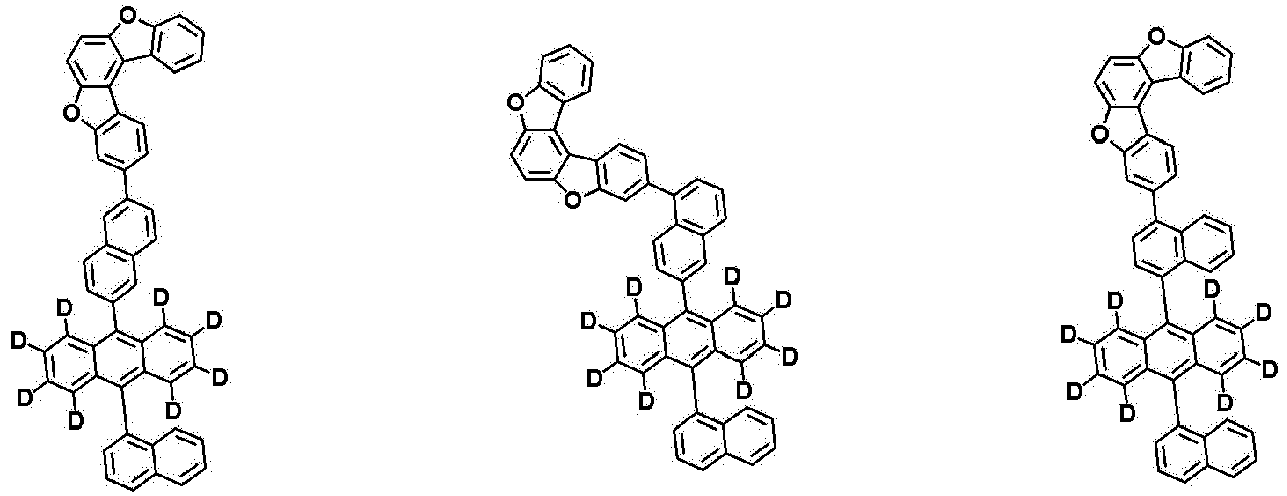

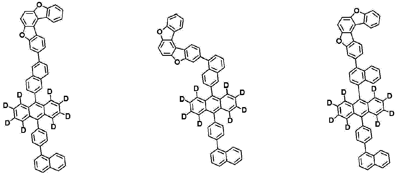


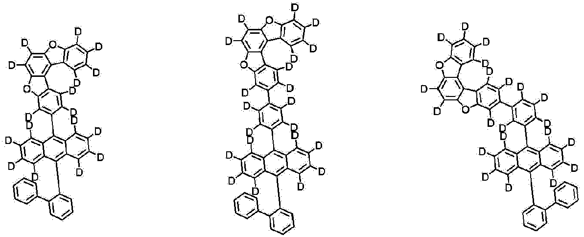


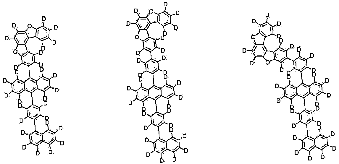


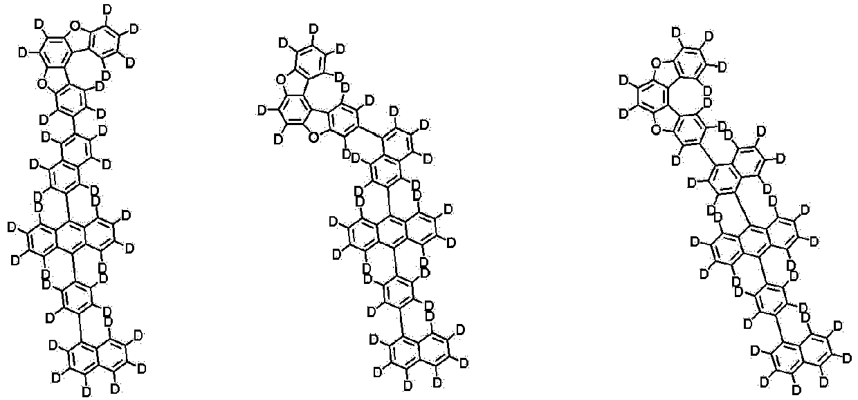


- The present specification provides an organic light emitting device including the above-described compound.
- When one member is disposed "on" another member in the present specification, this includes not only a case where the one member is brought into contact with another member, but also a case where still another member is present between the two members.
- When one part "includes" one constituent element in the present specification, unless otherwise specifically described, this does not mean that another constituent element is excluded, but means that another constituent element may be further included.
- In the present specification, the `layer' has a meaning compatible with a `film' usually used in the art, and means a coating covering a target region. The size of the `layer' is not limited, and the sizes of the respective 'layers' may be the same as or different from one another. According to an exemplary embodiment, the size of the `layer' may be the same as that of the entire device, may correspond to the size of a specific functional region, and may also be as small as a single sub-pixel.
- In the present specification, when a specific A material is included in a B layer, this means both i) the fact that one or more A materials are included in one B layer and ii) the fact that the B layer is composed of one or more layers, and the A material is included in one or more layers of the multi-layered B layer.
- In the present specification, when a specific A material is included in a C layer or a D layer, this means all of i) the fact that the A material is included in one or more layers of the C layer having one or more layers, ii) the fact that the A material is included in one or more layers of the D layer having one or more layers, and iii) the fact that the A material is included in each of the C layer having one or more layers and the D layer having one or more layers.
- The present specification provides an organic light emitting device including: a first electrode; a second electrode; and an organic material layer having one or more layers provided between the first electrode and the second electrode, in which one or more layers of the organic material layer include the compound represented by
Chemical Formula 1. - The organic material layer of the organic light emitting device of the present specification may also be composed of a single-layered structure, but may be composed of a multi-layered structure in which two or more organic material layers are stacked. For example, the organic material layer may have a structure including a hole injection layer, a hole transport layer, a light emitting layer, an electron transport layer, an electron injection layer, an electron blocking layer, a hole blocking layer, and the like. However, the structure of the organic light emitting device is not limited thereto, and may include a fewer number of organic layers.
- According to an exemplary embodiment of the present specification, the organic material layer includes a hole injection layer, a hole transport layer, or an electron blocking layer, and the hole injection layer, the hole transport layer, or the electron blocking layer includes the compound.
- According to an exemplary embodiment of the present specification, the organic material layer includes a light emitting layer, and the light emitting layer includes the compound.
- According to an exemplary embodiment of the present specification, the organic material layer includes a light emitting layer, and the light emitting layer includes the compound as a host of the light emitting layer.
- According to an exemplary embodiment of the present specification, the light emitting layer includes a dopant, and the dopant includes one or more selected from the group consisting of a fluorescent dopant, a phosphorescent dopant, and a thermally delayed fluorescent dopant.
- According to an exemplary embodiment of the present specification, the fluorescent dopant includes one or more selected from the group consisting of an arylamine-based compound and a boron-based compound.
- According to an exemplary embodiment of the present specification, the fluorescent dopant is an arylamine-based compound.
- According to an exemplary embodiment of the present specification, the fluorescent dopant is a boron-based compound.
- According to an exemplary embodiment of the present specification, the organic material layer includes a light emitting layer, the light emitting layer includes a host and a dopant, the host includes the compound, and the dopant includes one or more selected from the group consisting of the fluorescent dopant, the phosphorescent dopant, and the thermally delayed fluorescent dopant.
- According to an exemplary embodiment of the present specification, the arylamine-based compound is represented by the following Chemical Formula D-1.

- In Chemical Formula D-1,
- L101 and L102 are the same as or different from each other, and are each independently a direct bond; or a substituted or unsubstituted arylene group, and
- Ar101 to Ar104 are the same as or different from each other, and are each independently a substituted or unsubstituted aryl group; or a substituted or unsubstituted heteroaryl group.
- According to an exemplary embodiment of the present specification, L101 and L102 are a direct bond.
- According to an exemplary embodiment of the present specification, Ar101 to Ar104 are the same as or different from each other, and are each independently a substituted or unsubstituted monocyclic or polycyclic aryl group having 6 to 30 carbon atoms; or a substituted or unsubstituted monocyclic or polycyclic heteroaryl group having 2 to 30 carbon atoms.
- According to an exemplary embodiment of the present specification, Ar101 to Ar104 are the same as or different from each other, and are each independently a monocyclic or polycyclic aryl group having 6 to 30 carbon atoms, which is unsubstituted or substituted with a straight-chained or branched alkyl group having 1 to 30 carbon atoms; or a monocyclic or polycyclic heteroaryl group having 2 to 30 carbon atoms.
- According to an exemplary embodiment of the present specification, Ar101 to Ar104 are the same as or different from each other, and are each independently a phenyl group substituted with a methyl group; or a dibenzofuran group.
- According to an exemplary embodiment of the present specification, Chemical Formula D-1 is represented by the following compound.
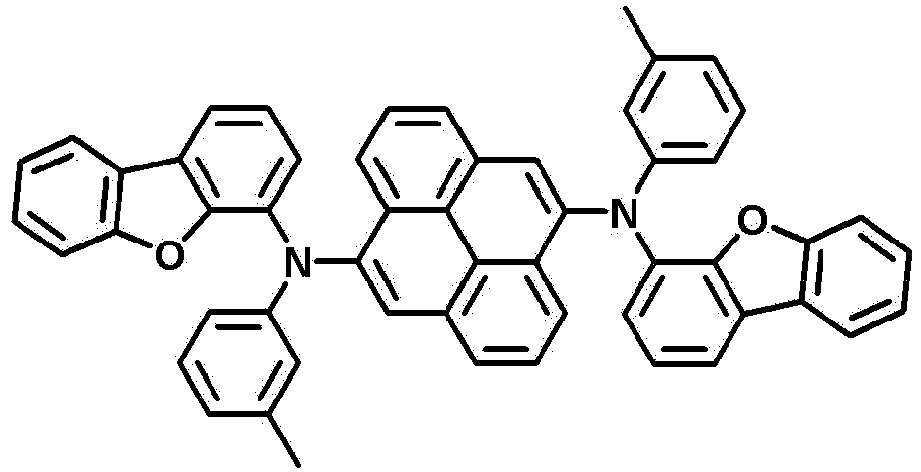
- According to an exemplary embodiment of the present specification, the boron-based compound is represented by the following Chemical Formula D-2.

- In Chemical Formula D-2,
- T1 to T5 are the same as or different from each other, and are each independently hydrogen; a substituted or unsubstituted alkyl group; a substituted or unsubstituted amine group; or a substituted or unsubstituted aryl group,
- t3 and t4 are each an integer from 1 to 4,
- t5 is an integer from 1 to 3,
- when t3 is 2 or higher, two or more T3's are the same as or different from each other,
- when t4 is 2 or higher, two or more T4's are the same as or different from each other, and
- when t5 is 2 or higher, two or more T5's are the same as or different from each other.
- According to an exemplary embodiment of the present specification, T1 to T5 are the same as or different from each other, and are each independently hydrogen; a substituted or unsubstituted straight-chained or branched alkyl group having 1 to 30 carbon atoms; a substituted or unsubstituted monocyclic or polycyclic arylamine group having 6 to 30 carbon atoms; or a substituted or unsubstituted monocyclic or polycyclic aryl group having 6 to 30 carbon atoms.
- According to an exemplary embodiment of the present specification, T1 to T5 are the same as or different from each other, and are each independently hydrogen; a straight-chained or branched alkyl group having 1 to 30 carbon atoms; a monocyclic or polycyclic arylamine group having 6 to 30 carbon atoms; or a monocyclic or polycyclic aryl group having 6 to 30 carbon atoms, which is unsubstituted or substituted with a straight-chained or branched alkyl group having 1 to 30 carbon atoms.
- According to an exemplary embodiment of the present specification, T1 to T5 are the same as or different from each other, and are each independently hydrogen; a tert-butyl group; a diphenylamine group; or a phenyl group unsubstituted or substituted with a tert-butyl group.
- According to an exemplary embodiment of the present specification, Chemical Formula D-2 is represented by the following compound.

- According to an exemplary embodiment of the present specification, as the phosphorescent dopant and the thermally delayed fluorescent dopant, those known in the art are used, but the phosphorescent dopant and the thermally delayed fluorescent dopant are not limited thereto.
- According to an exemplary embodiment of the present specification, the light emitting layer includes the host and the dopant at a weight ratio of 99:1 to 1:99. The light emitting layer includes the host and the dopant specifically, at a weight ratio of 99:1 to 50:50, and more specifically, at a weight ratio of 99:1 to 95:5.
- According to an exemplary embodiment of the present specification, the organic light emitting device further includes one or two or more layers selected from the group consisting of a hole injection layer, a hole transport layer, a light emitting layer, an electron transport layer, an electron injection layer, a hole blocking layer, and an electron blocking layer.
- According to an exemplary embodiment of the present specification, the organic light emitting device includes: a first electrode; a second electrode; a light emitting layer provided between the first electrode and the second electrode; and an organic material layer having two or more layers provided between the light emitting layer and the first electrode, or between the light emitting layer and the second electrode.
- According to an exemplary embodiment of the present specification, as the organic material layer having two or more layers between the light emitting layer and the first electrode, or between the light emitting layer and the second electrode, two or more may be selected from the group consisting of a light emitting layer, a hole transport layer, a hole injection layer, a hole injection and transport layer, an electron blocking layer, a hole blocking layer, an electron injection layer, an electron transport layer, and an electron injection and transport layer.
- According to an exemplary embodiment of the present specification, a hole injection layer having two or more layers is included between the light emitting layer and the first electrode. The hole injection layer having two or more layers may include materials which are the same as or different from each other.
- According to an exemplary embodiment of the present specification, a hole transport layer having two or more layers is included between the light emitting layer and the first electrode. The hole transport layer having two or more layers may include materials which are the same as or different from each other.
- According to an exemplary embodiment of the present specification, an electron transport layer having two or more layers is included between the light emitting layer and the second electrode. The electron transport layer having two or more layers may include materials which are the same as or different from each other.
- According to an exemplary embodiment of the present specification, the first electrode is an anode or a cathode.
- According to an exemplary embodiment of the present specification, the second electrode is a cathode or an anode.
- According to an exemplary embodiment of the present specification, the organic light emitting device may be a normal type organic light emitting device in which an anode, an organic material layer having one or more layers, and a cathode are sequentially stacked on a substrate.
- According to an exemplary embodiment of the present specification, the organic light emitting device may be an inverted type organic light emitting device in which a cathode, an organic material layer having one or more layers, and an anode are sequentially stacked on a substrate.
- For example, the structure of the organic light emitting device according to an exemplary embodiment of the present specification is exemplified in
FIGS. 1 and 2. FIGS. 1 and 2 exemplify an organic light emitting device, and the organic light emitting device is not limited thereto. -
FIG. 1 exemplifies a structure of an organic light emitting device in which afirst electrode 2, alight emitting layer 4, and asecond electrode 3 are sequentially stacked on asubstrate 1. The compound ofChemical Formula 1 is included in thelight emitting layer 4. -
FIG. 2 exemplifies a structure of an organic light emitting device in which asubstrate 1, afirst electrode 2, a firsthole injection layer 5, a secondhole injection layer 6, ahole transport layer 7, anelectron blocking layer 8, alight emitting layer 4, a firstelectron transport layer 9, a secondelectron transport layer 10, anelectron injection layer 11, and asecond electrode 3 are sequentially stacked. In the structure described above, the compound may be included in thelight emitting layer 4. - The organic light emitting device of the present specification may be manufactured by the materials and methods known in the art, except that the light emitting layer includes the compound, that is, the compound represented by
Chemical Formula 1. - When the organic light emitting device includes a plurality of organic material layers, the organic material layers may be formed of the same material or different materials.
- For example, the organic light emitting device of the present specification may be manufactured by sequentially stacking a first electrode, an organic material layer, and a second electrode on a substrate. In this case, the organic light emitting device may be manufactured by depositing a metal or a metal oxide having conductivity, or an alloy thereof on a substrate to form an anode, forming an organic material layer including a hole injection layer, a hole transport layer, a light emitting layer, and an electron transport layer thereon, and then depositing a material, which may be used as a cathode, thereon, by using a physical vapor deposition (PVD) method such as sputtering or e-beam evaporation. In addition to the method described above, an organic light emitting device may be manufactured by sequentially depositing a second electrode material, an organic material layer, and a first electrode material on a substrate.
- Further, the compound represented by
Chemical Formula 1 may be formed as an organic material layer by not only a vacuum deposition method, but also a solution application method when an organic light emitting device is manufactured. Here, the solution application method means spin coating, dip coating, doctor blading, inkjet printing, screen printing, a spray method, roll coating, and the like, but is not limited thereto. - In addition to the method described above, an organic light emitting device may be made by sequentially depositing a second electrode material, an organic material layer, and a first electrode material on a substrate. However, the manufacturing method is not limited thereto.
- As the first electrode material, materials having a high work function are usually preferred so as to facilitate the injection of holes into an organic material layer. Examples thereof include: a metal, such as vanadium, chromium, copper, zinc, and gold, or an alloy thereof; a metal oxide, such as zinc oxide, indium oxide, indium tin oxide (ITO), and indium zinc oxide (IZO); a combination of a metal and an oxide, such as ZnO:Al or SnO2:Sb; a conductive polymer, such as poly(3-methylthiophene), poly[3,4-(ethylene-1,2-dioxy)thiophene] (PEDOT), polypyrrole, and polyaniline; and the like, but are not limited thereto.
- As the second electrode material, materials having a low work function are usually preferred so as to facilitate the injection of electrons into an organic material layer. Examples thereof include: a metal, such as magnesium, calcium, sodium, potassium, titanium, indium, yttrium, lithium, gadolinium, aluminum, silver, tin, and lead, or an alloy thereof; a multi-layer structured material, such as LiF/Al or LiO2/Al; and the like, but are not limited thereto.
- The light emitting layer may include a host material and a dopant material. When an additional light emitting layer is included in addition to a light emitting layer including the compound represented by
Chemical Formula 1 according to an exemplary embodiment of the present specification, examples of a host material include a fused and/or non-fused aromatic ring derivative, a hetero ring-containing compound, or the like. Specific examples of the fused aromatic ring derivative include anthracene derivatives, pyrene derivatives, naphthalene derivatives, pentacene derivatives, phenanthrene compounds, fluoranthene compounds, and the like, and specific examples of the hetero ring-containing compound include dibenzofuran derivatives, ladder-type furan compounds, pyrimidine derivatives, and the like, but the examples are not limited thereto. - Examples of the dopant material include an aromatic amine derivative, a styrylamine compound, a boron complex, a fluoranthene compound, a metal complex, and the like. Specifically, the aromatic amine derivative is a fused aromatic ring derivative having a substituted or unsubstituted arylamine group, and examples thereof include pyrene, anthracene, chrysene, periflanthene, and the like having an arylamine group. Further, the styrylamine compound is a compound in which a substituted or unsubstituted arylamine is substituted with at least one arylvinyl group, and one or two or more substituents selected from the group consisting of an aryl group, a silyl group, an alkyl group, a cycloalkyl group, and an arylamine group are substituted or unsubstituted. Specific examples thereof include styrylamine, styryldiamine, styryltriamine, styryltetramine, and the like, but are not limited thereto. Further, examples of the metal complex include an iridium complex, a platinum complex, and the like, but are not limited thereto.
- The hole injection layer is a layer which accepts holes from an electrode. It is preferred that hole injection material has an ability to transport holes, and has an effect of accepting holes from an anode and an excellent hole injection effect for a light emitting layer or a light emitting material. Further, the hole injection material is preferably a material which is excellent in ability to prevent excitons produced from a light emitting layer from moving to an electron injection layer or an electron injection material. In addition, the hole injection material is preferably a material which is excellent in ability to form a thin film. In addition, the highest occupied molecular orbital (HOMO) of the hole injection material is preferably a value between the work function of the anode material and the HOMO of the neighboring organic material layer. Specific examples of the hole injection material include: metal porphyrin, oligothiophene, and arylamine-based organic materials; hexanitrile hexaazatriphenylene-based organic materials; quinacridone-based organic materials; perylene-based organic materials; polythiophene-based conductive polymers such as anthraquinone and polyaniline; and the like, but are not limited thereto.
- According to an exemplary embodiment of the present specification, the hole injection layer includes a compound represented by the following Chemical Formula HI-1, but is not limited thereto.


- In Chemical Formula HI-1,
- R300 to R308 are the same as or different from each other, and are each independently hydrogen; deuterium; a cyano group; a substituted or unsubstituted alkyl group; a substituted or unsubstituted amine group; a substituted or unsubstituted aryl group; or a substituted or unsubstituted heteroaryl group, or are bonded to an adjacent group to form a substituted or unsubstituted ring,
- r301 and r302 are each an integer from 1 to 4,
- r303 and r304 are each an integer from 1 to 3,
- when r301 is 2 or higher, R301's are the same as or different from each other,
- when r302 is 2 or higher, R302's are the same as or different from each other,
- when r303 is 2 or higher, R303's are the same as or different from each other, and
- when r304 is 2 or higher, R304's are the same as or different from each other.
- According to an exemplary embodiment of the present specification, R301 to R304 are hydrogen.
- According to an exemplary embodiment of the present specification, R300 is a substituted or unsubstituted aryl group.
- According to an exemplary embodiment of the present specification, R300 is a monocyclic or polycyclic aryl group having 6 to 30 carbon atoms.
- According to an exemplary embodiment of the present specification, R300 is a phenyl group.
- According to an exemplary embodiment of the present specification, R300 is boned to R301 or R302 to form a substituted or unsubstituted ring.
- According to an exemplary embodiment of the present specification, R300 is bonded to R301 or R302 to form an indole ring.
- According to an exemplary embodiment of the present specification, R305 to R308 are the same as or different from each other, and are each independently a substituted or unsubstituted aryl group; or a substituted or unsubstituted heteroaryl group.
- According to an exemplary embodiment of the present specification, R305 to R308 are the same as or different from each other, and are each independently a monocyclic or polycyclic aryl group having 6 to 30 carbon atoms; or a monocyclic or polycyclic heteroaryl group having 2 to 30 carbon atoms, which is unsubstituted or substituted with a monocyclic or polycyclic aryl group having 6 to 30 carbon atoms.
- According to an exemplary embodiment of the present specification, R305 to R308 are the same as or different from each other, and are each independently a phenyl group; or a carbazole group unsubstituted or substituted with a phenyl group.
- According to an exemplary embodiment of the present specification, Chemical Formula HI-1 is represented by the following compound.

- According to an exemplary embodiment of the present specification, the hole injection layer includes a compound represented by the following Chemical Formula HI-2, but is not limited thereto.


- In Chemical Formula HI-2,
- at least one of X'1 to X'6 is N, and the others are CH, and
- R309 to R314 are the same as or different from each other, and are each independently hydrogen; deuterium; a cyano group; a substituted or unsubstituted alkyl group; a substituted or unsubstituted amine group; a substituted or unsubstituted aryl group; or a substituted or unsubstituted heteroaryl group, or are bonded to an adjacent group to form a substituted or unsubstituted ring.
- According to an exemplary embodiment of the present specification, X'1 to X'6 are N.
- According to an exemplary embodiment of the present specification, R309 to R314 are a cyano group.
- According to an exemplary embodiment of the present specification, Chemical Formula HI-2 is represented by the following compound.

- The hole transport layer is a layer which accepts holes from a hole injection layer and transports the holes to a light emitting layer. A hole transport material is preferably a material having high hole mobility which may accept holes from an anode or a hole injection layer and transfer the holes to a light emitting layer. Specific examples thereof include arylamine-based organic materials, conductive polymers, block copolymers having both conjugated portions and non-conjugated portions, and the like, but are not limited thereto.
- According to an exemplary embodiment of the present specification, the hole transport layer includes a compound represented by the following Chemical Formula HT-1, but is not limited thereto.

- In Chemical Formula HT-1,
- R315 to R317 are the same as or different from each other, and are each independently any one selected from the group consisting of hydrogen; deuterium; a substituted or unsubstituted alkyl group; a substituted or unsubstituted aryl group; a substituted or unsubstituted heteroaryl group; and a combination thereof, or are bonded to an adjacent group to form a substituted or unsubstituted ring,
- r315 is an integer from 1 to 5, and when r315 is 2 or higher, two or more R315's are the same as or different from each other, and
- r316 is an integer from 1 to 5, and when r316 is 2 or higher, two or more R316's are the same as or different from each other.
- According to an exemplary embodiment of the present specification, R317 is any one selected from the group consisting of a substituted or unsubstituted aryl group; a substituted or unsubstituted heteroaryl group; and a combination thereof.
- According to an exemplary embodiment of the present specification, R317 is any one selected from the group consisting of a carbazole group; a phenyl group; a biphenyl group; and a combination thereof.
- According to an exemplary embodiment of the present specification, R315 and R316 are the same as or different from each other, and are each independently a substituted or unsubstituted aryl group, or are bonded to an adjacent group to form an aromatic hydrocarbon ring substituted with an alkyl group.
- According to an exemplary embodiment of the present specification, R315 and R316 are the same as or different from each other, and are each independently a phenyl group, or are bonded to an adjacent group to form indene substituted with a methyl group.
- According to an exemplary embodiment of the present specification, Chemical Formula HT-1 is represented by any one of the following compounds.

- The electron transport layer is a layer which accepts electrons from an electron injection layer and transports the electrons to a light emitting layer. An electron transport material is preferably a material having high electron mobility which may proficiently accept electrons from a cathode and transfer the electrons to a light emitting layer. Specific examples thereof include: Al complexes of 8-hydroxyquinoline; complexes including Alq3; organic radical compounds; hydroxyflavone-metal complexes; and the like, but are not limited thereto. The electron transport layer may be used with any desired cathode material, as used according to the related art. In particular, an appropriate cathode material is a typical material which has a low work function, followed by an aluminum layer or a silver layer. Specific examples thereof include cesium, barium, calcium, ytterbium, and samarium, in each case followed by an aluminum layer or a silver layer.
- According to an exemplary embodiment of the present specification, the electron transport layer includes a compound represented by the following Chemical Formula ET-1.

- In Chemical Formula ET-1,
- at least one of X'7 and X'8 is N, and the other is CH,
- R318 to R323 are the same as or different from each other, and are each independently hydrogen; deuterium; a cyano group; a substituted or unsubstituted alkyl group; a substituted or unsubstituted amine group; a substituted or unsubstituted aryl group; or a substituted or unsubstituted heteroaryl group, or are bonded to an adjacent group to form a substituted or unsubstituted ring,
- L'1 is a direct bond; a substituted or unsubstituted arylene group; or a substituted or unsubstituted heteroarylene group,
- r322 is an integer from 1 to 7, and when r322 is 2 or higher, R322's are the same as or different from each other, and
- l'1 is an integer from 1 to 5, and when l'1 is 2 or higher, L'1's are the same as or different from each other.
- According to an exemplary embodiment of the present specification, R318 to R323 are the same as or different from each other, and are each independently hydrogen; or a substituted or unsubstituted aryl group, or adjacent groups are bonded to each other to form a substituted or unsubstituted aromatic hydrocarbon ring.
- According to an exemplary embodiment of the present specification, R318 to R323 are the same as or different from each other, and are each independently hydrogen; a phenyl group; or a naphthyl group, or adjacent groups are bonded to each other to form a benzene.
- According to an exemplary embodiment of the present specification, L'1 is a substituted or unsubstituted arylene group.
- According to an exemplary embodiment of the present specification, L'1 is a phenylene group.
- According to an exemplary embodiment of the present specification, ET-1 is represented by the following compound.

- According to an exemplary embodiment of the present specification, the electron transport layer includes a compound represented by the following Chemical Formula ET-2.
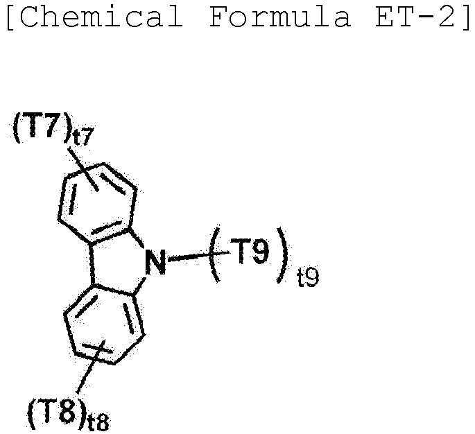
- In Chemical Formula ET-2,
- T7 to T9 are the same as or different from each other, and are each independently any one selected from the group consisting of hydrogen; deuterium; a cyano group; a substituted or unsubstituted alkyl group; a substituted or unsubstituted amine group; a substituted or unsubstituted aryl group; a substituted or unsubstituted heteroaryl group; and a combination thereof, or are bonded to an adjacent group to form a substituted or unsubstituted ring,
- t7 is an integer from 1 to 4, and when t7 is 2 or higher, two or more T1's are the same as or different from each other,
- t8 is an integer from 1 to 4, and when t8 is 2 or higher, two or more T2's are the same as or different from each other, and
- t9 is an integer from 1 to 10, and when t9 is 2 or higher, two or more T3's are the same as or different from each other.
- According to an exemplary embodiment of the present specification, T7 to T9 are the same as or different from each other, and are each independently any one selected from the group consisting of hydrogen; a substituted or unsubstituted aryl group; and a substituted or unsubstituted heteroaryl group, and a combination thereof.
- According to an exemplary embodiment of the present specification, T7 to T9 are the same as or different from each other, and are each independently any one selected from the group consisting of hydrogen; a carbazole group; a phenyl group; a biphenyl group; a triazine group; and a combination thereof.
- According to an exemplary embodiment of the present specification, ET-2 is represented by the following compound.

- The electron transport layer may further include a metal complex. As the metal, a metal used in the art may be used.
- The electron injection layer is a layer which accepts electrons from an electrode. It is preferred that an electron injection material is excellent in ability to transport electrons and has an effect of accepting electrons from the cathode and an excellent electron injection effect for a light emitting layer or a light emitting material. Further, the electron injection material is preferably a material which prevents excitons produced from a light emitting layer from moving to a hole injection layer and is excellent in ability to form a thin film. Specific examples thereof include fluorenone, anthraquinodimethane, diphenoquinone, thiopyran dioxide, oxazole, oxadiazole, triazole, imidazole, perylenetetracarboxylic acid, fluorenylidene methane, anthrone, and the like, and derivatives thereof, metal complex compounds, nitrogen-containing 5-membered ring derivatives, and the like, but are not limited thereto.
- Examples of the metal complex compounds include 8-hydroxyquinolinato lithium, bis(8-hydroxyquinolinato) zinc, bis(8-hydroxyquinolinato) copper, bis(8-hydroxyquinolinato) manganese, tris(8-hydroxyquinolinato) aluminum, tris(2-methyl-8-hydroxyquinolinato) aluminum, tris(8-hydroxyquinolinato) gallium, bis(10-hydroxybenzo[h]quinolinato) beryllium, bis(10-hydroxybenzo[h]quinolinato) zinc, bis(2-methyl-8-quinolinato) chlorogallium, bis(2-methyl-8-quinolinato)(o-cresolato) gallium, bis(2-methyl-8-quinolinato)(1-naphtholato) aluminum, bis(2-methyl-8-quinolinato)(2-naphtholato) gallium, and the like, but are not limited thereto.
- The electron blocking layer is a layer which may improve the service life and efficiency of a device by preventing electrons injected from an electron injection layer from passing through a light emitting layer and entering a hole injection layer. As the electron blocking layer, the publicly-known material can be used without limitation, and the electron blocking layer may be formed between a light emitting layer and a hole injection layer, between a light emitting layer and a hole transport layer, or between a light emitting layer and a layer which simultaneously injects and transports holes.
The hole blocking layer is a layer which blocks holes from reaching a cathode, and may be generally formed under the same conditions as those of the electron injection layer. Specific examples thereof include oxadiazole derivatives or triazole derivatives, phenanthroline derivatives, aluminum complexes, and the like, but are not limited thereto. - The organic light emitting device according to the present specification may be a top emission type, a bottom emission type, or a dual emission type according to the materials to be used.
- The organic light emitting device according to the present specification may be included and used in various electronic devices. For example, the electronic device may be a display panel, a touch panel, a solar module, a lighting device, and the like, and is not limited thereto.
- Hereinafter, the present specification will be described in detail with reference to Examples, Comparative Examples, and the like for specifically describing the present specification. However, the Examples and the Comparative Examples according to the present specification may be modified in various forms, and it is not interpreted that the scope of the present specification is limited to the Examples and the Comparative Examples described below in detail. The Examples and the Comparative Examples of the present specification are provided to more completely explain the present specification to a person with ordinary skill in the art.
-

- 3-Chloro-benzo[1,2-b:4,3-b']bisbenzofuran (50 g, 170.81 mmol), bis(pinacolato)diboron (54.3 g, 256.22 mmol), tricyclohexylphosphine (1.9 g, 6.7 mmol), potassium acetate (33.5 g, 341.6 mmol) and Pd(dba)2 (1.9 g, 3.4 mmol) were added to 1,4-dioxane (400 ml), and the resulting solution was refluxed for 6 hours. The reaction solution was cooled, and the organic layer was extracted with ethyl acetate, and then dried over anhydrous magnesium sulfate. The organic solvent was removed under reduced pressure, and the residue was purified using column chromatography to obtain Compound Core-1 (44.0 g, yield 67%).
MS: [M+H]+ = 385 -

- After Compound Core-1 (40 g, 104.1 mmol) and 1-bromo-3-chlorobenzene (18.9 g, 98.9 mmol) were dissolved in THF (400 ml), Pd(PPh3)4 (1.2 g, 1.0 mmol) and 80 ml of an aqueous 2M K2CO3 solution were added thereto, and the resulting solution was refluxed for 4 hours. The reaction solution was cooled, and the organic layer was extracted with ethyl acetate, and then dried over anhydrous magnesium sulfate. The organic solvent was removed under reduced pressure, and the residue was purified using column chromatography to obtain Compound Core-2-a (23.7 g, yield 65%) .
MS: [M+H]+ = 369 - Compound Core-2 was obtained by performing synthesis and purification in the same manner as in <1-a> Preparation of Compound Core-1 of Synthesis Example 1, except that Compound Core-2-a was used instead of 3-chloro-benzo[1,2-b:4,3-b']bisbenzofuran in <1-a> Preparation of Compound Core-1 of Synthesis Example 1.
MS: [M+H]+ = 461 -

- Compound Core-3-a was obtained by performing synthesis and purification in the same manner as in <2-a> Preparation of Compound Core-2-a of Synthesis Example 2, except that 1-bromo-4-chlorobenzene was used instead of 1-bromo-3-chlorobenzene in <2-a> Preparation of Compound Core-2-a of Synthesis Example 2.
MS: [M+H]+ = 369 - Compound Core-3 was obtained by performing synthesis and purification in the same manner as in <1-a> Preparation of Compound Core-1 of Synthesis Example 1, except that Compound Core-3-a was used instead of 3-chloro-benzo[1,2-b:4,3-b']bisbenzofuran in <1-a> Preparation of Compound Core-1 of Synthesis Example 1.
MS: [M+H]+ = 461 -

- Compound Core-4-a was obtained by performing synthesis and purification in the same manner as in <2-a> Preparation of Compound Core-2-a of Synthesis Example 2, except that 1-bromo-6-chloronaphthalene was used instead of 1-bromo-3-chlorobenzene in <2-a> Preparation of Compound Core-2-a of Synthesis Example 2.
MS: [M+H]+ = 419 - Compound Core-4 was obtained by performing synthesis and purification in the same manner as in <1-a> Preparation of Compound Core-1 of Synthesis Example 1, except that Compound Core-4-a was used instead of 3-chloro-benzo[1,2-b:4,3-b']bisbenzofuran in <1-a> Preparation of Compound Core-1 of Synthesis Example 1.
MS: [M+H]+ = 511 -

- Compound BH-1 was obtained by performing synthesis and purification in the same manner as in <2-a> Preparation of Compound Core-2-a of Synthesis Example 2, except that 9-bromo-10-phenylanthracene-1,2,3,4,5,6,7,8-d8 was used instead of 1-bromo-3-chlorobenzne in <2-a> Preparation of Compound Core-2-a of Synthesis Example 2.
MS: [M+H]+ = 519 -

- Compound BH-2 was obtained by performing synthesis and purification in the same manner as in <2-a> Preparation of Compound Core-2-a of Synthesis Example 2, except that 9-bromo-10-(naphthalen-1-yl)anthracene-1,2,3,4,5,6,7,8-d8 was used instead of 1-bromo-3-chlorobenzene, and Compound Core-2 was used instead of Compound Core-1 in <2-a> Preparation of Compound Core-2-a of Synthesis Example 2.
MS: [M+H]+ = 645 -

- Compound BH-3-a was obtained by performing synthesis and purification in the same manner as in <2-a> Preparation of Compound Core-2-a of Synthesis Example 2, except that 9-bromoanthracene was used instead of 1-bromo-3-chlorobenzene in <2-a> Preparation of Compound Core-2-a of Synthesis Example 2.
MS: [M+H]+ = 435 - Compound BH-3-a (40 g, 92.1mmol) and AlCl3 (8 g, 60 mmol) were added to C6D6 (800 ml), and the resulting solution was stirred for 5 hours. After the reaction was completed, D2O (50ml) was added thereto, the resulting solution was stirred for 30 minutes, and then trimethylamine (5ml) was added dropwise thereto. The reaction solution was transferred to a separatory funnel, and an extraction with water and toluene was performed. The extract was dried over MgSO4, and then recrystallized with ethyl acetate to obtain BH-3-b (27.9 g, yield 67%).
MS: [M+H]+ = 453 - After Compound BH-3-b (30 g, 66.3 mmol) was dispersed in 250 ml of dimethylformamide, a solution of n-bromosuccinimide (12.4 g, 69.6 mmol) dissolved in 50 ml of dimethylformamide was slowly added dropwise thereto. After reaction at room temperature for 4 hours, 600 ml of water was added dropwise thereto. When a solid was produced, the solid was filtered, and then dissolved in ethyl acetate, and the resulting solution was put into a separatory funnel, and then washed several times with distilled water. The resulting product was recrystallized in EA to obtain Compound BH-3-c (29.9 g, yield 85%).
MS: [M+H]+ = 531 - Compound BH-3 was obtained by performing synthesis and purification in the same manner as in <2-a> Preparation of Compound Core-2-a of Synthesis Example 2, except that Compound BH-3-c was used instead of 1-bromo-3-chlorobenzene and [1,1'-biphenyl]-2-ylboronic acid was used instead of Compound Core-1 in <2-a> Preparation of Compound Core-2-a of Synthesis Example 2.
MS: [M+H]+ = 604 -

- Compound BH-4 was obtained by performing synthesis and purification in the same manner as in <2-a> Preparation of Compound Core-2-a of Synthesis Example 2, except that 9-bromo-10-(naphthalen-1-yl)anthracene-1,2,3,4,5,6,7,8-d8 was used instead of 1-bromo-3-chlorobenzene in <2-a> Preparation of Compound Core-2-a of Synthesis Example 2.
MS: [M+H]+ = 569 -
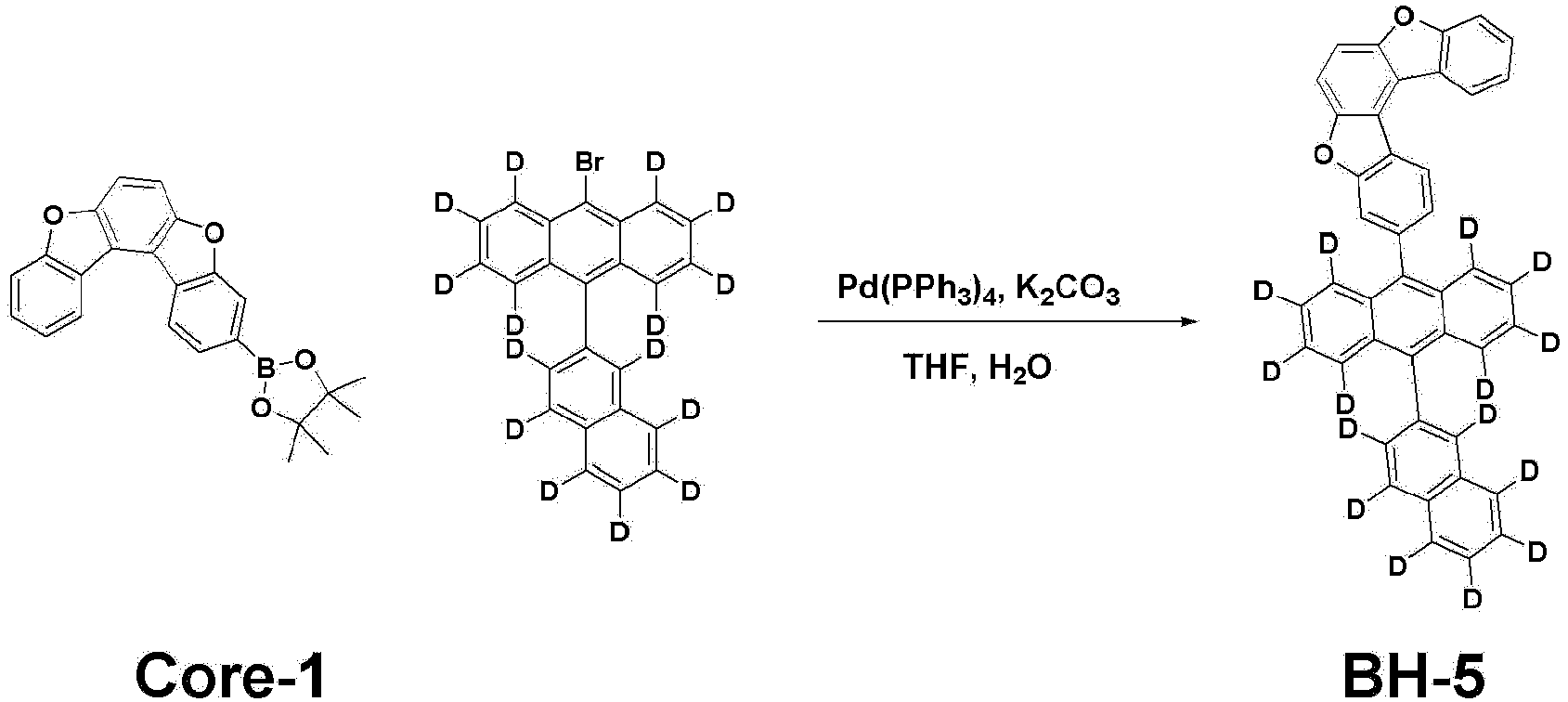
- Compound BH-5 was obtained by performing synthesis and purification in the same manner as in <2-a> Preparation of Compound Core-2-a of Synthesis Example 2, except that 9-bromo-10-(naphthalen-2-yl-d7)anthracene-1,2,3,4,5,6,7,8-d8 was used instead of 1-bromo-3-chlorobenzene in <2-a> Preparation of Compound Core-2-a of Synthesis Example 2.
MS: [M+H]+ = 576 -
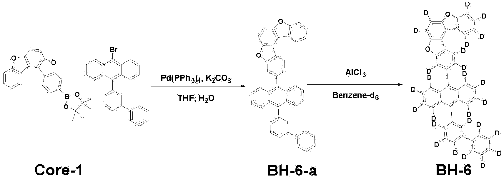
- Compound BH-6-a was obtained by performing synthesis and purification in the same manner as in <2-a> Preparation of Compound Core-2-a of Synthesis Example 2, except that 9-([1,1'-biphenyl]-3-yl)-10-bromoanthracene was used instead of 1-bromo-3-chlorobenzene in <2-a> Preparation of Compound Core-2-a of Synthesis Example 2.
MS: [M+H]+ = 587 - Compound BH-6 was obtained by performing synthesis and purification in the same manner as in <7-b> Preparation of Compound BH-3-b of Synthesis Example 7, except that Compound BH-6-a was used instead of Compound BH-3-a in <7-b> Preparation of Compound BH-3-b of Synthesis Example 7.
MS: [M+H]+ = 613 -
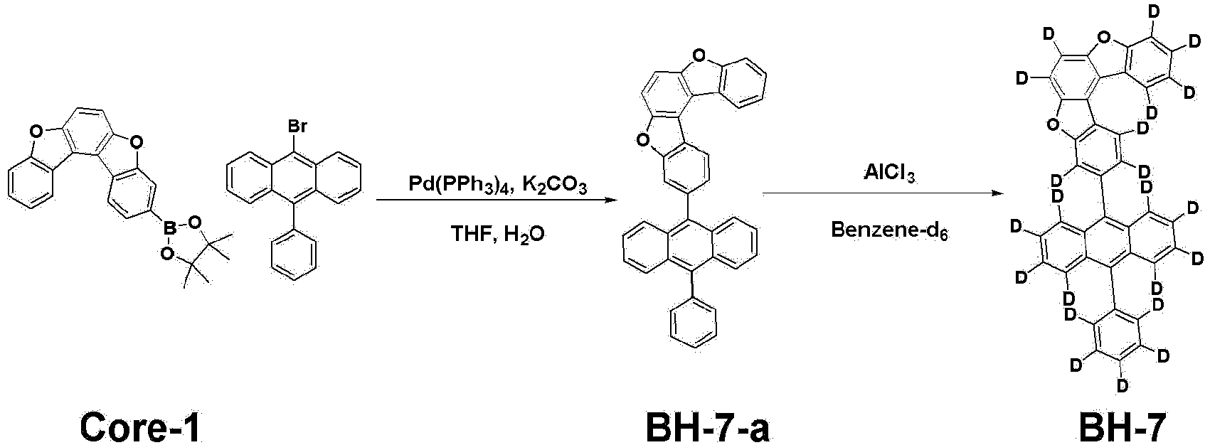
- Compound BH-7-a was obtained by performing synthesis and purification in the same manner as in <2-a> Preparation of Compound Core-2-a of Synthesis Example 2, except that 9-bromo-10-phenylanthracene was used instead of 1-bromo-3-chlorobenzene in <2-a> Preparation of Compound Core-2-a of Synthesis Example 2.
MS: [M+H]+ = 511 - Compound BH-7 was obtained by performing synthesis and purification in the same manner as in <7-b> Preparation of Compound BH-3-b of Synthesis Example 7, except that Compound BH-7-a was used instead of Compound BH-3-a in <7-b> Preparation of Compound BH-3-b of Synthesis Example 7.
MS: [M+H]+ = 533 -

- Compound BH-8-a was obtained by performing synthesis and purification in the same manner as in <2-a> Preparation of Compound Core-2-a of Synthesis Example 2, except that Compound Core-3 was used instead of Compound Core-1 and 9-bromo-10-(naphthalen-1-yl)anthracene was used instead of 1-bromo-3-chlorobenzene in <2-a> Preparation of Compound Core-2-a of Synthesis Example 2.
MS: [M+H]+ = 637 - Compound BH-8 was obtained by performing synthesis and purification in the same manner as in <7-b> Preparation of Compound BH-3-b of Synthesis Example 7, except that Compound BH-8-a was used instead of Compound BH-3-a.
MS: [M+H]+ = 665 -

- Compound BH-9 was obtained by performing synthesis and purification in the same manner as in <2-a> Preparation of Compound Core-2-a of Synthesis Example 2, except that 9-bromo-10-(naphthalen-1-yl-d7)anthracene-1,2,3,4,5,6,7,8-d8 was used instead of 1-bromo-3-chlorobenzene in <2-a> Preparation of Compound Core-2-a of Synthesis Example 2.
MS: [M+H]+ = 576 -
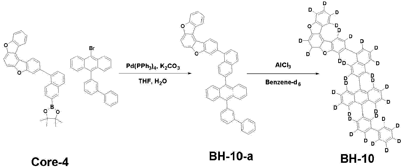
- Compound BH-10-a was obtained by performing synthesis and purification in the same manner as in <2-a> Preparation of Compound Core-2-a of Synthesis Example 2, except that Compound Core-4 was used instead of Compound Core-1 and 9-([1,1'-biphenyl]-3-yl)-10-bromoanthracene was used instead of 1-bromo-3-chlorobenzene in <2-a> Preparation of Compound Core-2-a of Synthesis Example 2.
MS: [M+H]+ = 713 - Compound BH-10 was obtained by performing synthesis and purification in the same manner as in <7-b> Preparation of Compound BH-3-b of Synthesis Example 7, except that Compound BH-10-a was used instead of Compound BH-3-a.
MS: [M+H]+ = 746 -

- Compound BH-11 was obtained by performing synthesis and purification in the same manner as in <2-a> Preparation of Compound Core-2-a of Synthesis Example 2, except that Compound BH-3-c was used instead of 1-bromo-3-chlorobenzene and [1,1'-biphenyl]-4-ylboronic acid was used instead of Compound Core-1 in <2-a> Preparation of Compound Core-2-a of Synthesis Example 2.
MS: [M+H]+ = 604 -

- Compound BH-12-a was obtained by performing synthesis and purification in the same manner as in <2-a> Preparation of Compound Core-2-a of Synthesis Example 2, except that 9-bromoanthracene was used instead of 1-bromo-3-chlorobenzene and Compound Core-3 was used instead of Compound Core-1 in <2-a> Preparation of Compound Core-2-a of Synthesis Example 2.
MS: [M+H]+ = 511 - Compound BH-12-b was obtained by performing synthesis and purification in the same manner as in <7-b> Preparation of Compound BH-3-b of Synthesis Example 7, except that Compound BH-12-a was used instead of Compound BH-3-a in <7-b> Preparation of Compound BH-3-b of Synthesis Example 7.
MS: [M+H]+ = 533 - Compound BH-12-c was obtained by performing synthesis and purification in the same manner as in <7-c> Preparation of Compound BH-3-b of Synthesis Example 7, except that Compound BH-12-b was used instead of Compound BH-3-a in <7-c> Preparation of Compound BH-3-c of Synthesis Example 7.
MS: [M+H]+ = 611 - Compound BH-12 was obtained by performing synthesis and purification in the same manner as in <2-a> Preparation of Compound Core-2-a of Synthesis Example 2, except that Compound BH-12-c and [1,1'-biphenyl]-4-ylboronic acid were used instead of 1-bromo-3-chlorobenzene and Compound Core-1, respectively.
MS: [M+H]+ = 684 - A glass substrate thinly coated with indium tin oxide (ITO) to have a thickness of 1,400 Å was put into distilled water in which a detergent was dissolved, and ultrasonically washed. In this case, a product manufactured by Fischer Co., was used as the detergent, and distilled water, which had been filtered twice with a filter manufactured by Millipore Co., was used as the distilled water. After the ITO was washed for 30 minutes, ultrasonic washing was conducted twice repeatedly using distilled water for 10 minutes. After the washing using distilled water was completed, ultrasonic washing was conducted by using isopropyl alcohol, acetone, and methanol solvents, and the resulting product was dried and then transported to a plasma washing machine. Furthermore, the substrate was cleaned by using oxygen plasma for 5 minutes, and then was transported to a vacuum deposition machine.
- The following HI-A and HATCN were thermally vacuum deposited to have a thickness of 650 Å and 50 Å, respectively, on the ITO transparent electrode prepared as described, thereby sequentially forming first and second hole injection layers. The following HT-A was vacuum deposited to have a thickness of 600 Å on the second hole injection layer, thereby forming a hole transport layer. The following HT-B was vacuum deposited to have a thickness of 50 Å on the hole transport layer, thereby forming an electron blocking layer.
- Subsequently, the following compound BD-A as a blue light emitting dopant was vacuum deposited at 4 wt% based on a total weight of the light emitting layer and the following BH-1 as a host was vacuum deposited at 96 wt% based on a total weight of the light emitting layer to a thickness of 200 Å on the electron blocking layer, thereby forming a light emitting layer.
- Next, the following compound ET-A as a first electron transport layer was vacuum deposited to have a thickness of 50 Å on the light emitting layer, and subsequently, the following ET-B and LiQ were vacuum deposited at a weight ratio of 1:1, thereby forming a second electron transport layer having a thickness of 360 Å. LiQ was vacuum deposited to have a thickness of 5 Å on the second electron transport layer, thereby forming an electron injection layer. Aluminum and silver were deposited at a weight ratio of 10:1 to have a thickness of 220 Å on the electron injection layer, and aluminum was deposited to have a thickness of 1,000 Å thereon, thereby forming a negative electrode.
- In the aforementioned procedure, the deposition rate of the organic materials was maintained at 0.4 to 0.9 Å/sec, the deposition rate of aluminum of the negative electrode was maintained at 2 Å/sec, and the degree of vacuum during the deposition was maintained at 1×10⁻⁷ to 5×10⁻⁸ torr, thereby manufacturing an organic light emitting device.


- Organic light emitting devices of Examples 2 to 12 were manufactured in the same manner as in Example 1, except that compounds described in the following Table 1 were used as hosts of the light emitting layer instead of Compound BH-1 in Example 1.


- Organic light emitting devices of Comparative Examples 1 to 5 were manufactured in the same manner as in Example 1, except that the following Compounds BH-a to BH-e were used as hosts of the light emitting layer instead of Compound BH-1 in Example 1.

- Voltages and conversion efficiencies (cd/A/y) when a current density of 10 mA/cm2 was applied to the organic light emitting devices in Examples 1 to 12 and Comparative Examples 1 to 5 and service lives (LT95) when a current density of 20 mA/cm2 was applied to the devices were measured, and the results are shown in the following Table 1. In this case, LT95 denotes the ratio of time taken for the luminance to decrease to 95% when the initial luminance at the current density of 20 mA/cm2 is set to 100%.
[Table 1] Light emitting layer 10 mA/cm2 20 mA/cm2 Host Driving voltage (V) Conversion efficiency (cd/A/y) LT95 (%) Example 1 BH-1 3.70 43.7 143 Example 2 BH-2 3.69 44.1 125 Example 3 BH-3 3.67 44.7 161 Example 4 BH-4 3.51 44.9 149 Example 5 BH-5 3.67 44.3 132 Example 6 BH-6 3.66 43.7 151 Example 7 BH-7 3.69 43.9 161 Example 8 BH-8 3.70 45.2 147 Example 9 BH-9 3.52 45.0 155 Example 10 BH-10 3.63 45.1 139 Example 11 BH-11 3.62 44.8 140 Example 12 BH-12 3.69 45.1 138 Comparative Example 1 BH-a 3.79 40.1 101 Comparative Example 2 BH-b 3.71 43.1 97 Comparative Example 3 BH-c 3.72 43.3 110 Comparative Example 4 BH-d 3.71 43.5 105 Comparative Example 5 BH-e 3.72 43.3 115 - The conversion efficiency (cd/A/y) takes a current efficiency (cd/A) to color purity (CIEy) of the material into consideration, and is an important reference value for efficiency in small and large organic light emitting devices targeting high luminance and high color gamut.
- In Table 1, Examples 1 to 12, which are organic light emitting devices in which the compound of
Chemical Formula 1 according to an exemplary embodiment of the present specification is used, include a compound including at least one deuterium in anthracene, Comparative Examples 1 and 2 include a compound which does not include deuterium, and Comparative Examples 3 to 5 include a compound which does not include deuterium in the anthracene core. - Specifically, since the compound that always includes deuterium in the anthracene according to an exemplary embodiment of the present invention has structural characteristics that the mobility of electrons and holes is improved and molecular stability is improved compared to Comparative Examples 1 and 2 which do not include deuterium and Comparative Examples 3 to 5 which do not include deuterium in the anthracene core, it could be seen that an organic light emitting device including the compound is excellent in terms of driving voltage, efficiency and service life.
Claims (11)
- A compound represented by the following Chemical Formula 1:
 wherein, in Chemical Formula 1,D is deuterium,L1 is a direct bond; or a substituted or unsubstituted arylene group,Ar1 is a substituted or unsubstituted aryl group,R1 to R9 are the same as or different from each other, and are each independently hydrogen; or deuterium, anda1 is an integer from 1 to 8.
 - The compound of claim 1, wherein Chemical Formula 1 is represented by the following Chemical Formula 1-1 or 1-2 :

 in Chemical Formulae 1-1 and 1-2,the definitions of D, Ar1, a1 and R1 to R9 are the same as those defined in Chemical Formula 1, andL11 is a substituted or unsubstituted arylene group.
 - The compound of claim 1, wherein Chemical Formula 1 is represented by the following Chemical Formula 1-3 or 1-4 :


 in Chemical Formulae 1-3 and 1-4,the definitions of D, Ar1, a1 and R1 to R9 are the same as those defined in Chemical Formula 1,a2 is an integer from 0 to 4,a3 is an integer from 0 to 4,a4 is an integer from 0 to 4, and
- The compound of claim 1, wherein L1 is a direct bond; or a monocyclic or polycyclic arylene group having 6 to 30 carbon atoms, which is unsubstituted or substituted with deuterium, and Ar1 is a monocyclic or polycyclic aryl group having 6 to 30 carbon atoms, which is unsubstituted or substituted with one or more substituents of deuterium, a monocyclic or polycyclic aryl group having 6 to 30 carbon atoms, and a combination thereof.
- The compound of claim 1, wherein Chemical Formula 1 is any one selected from the following compounds:


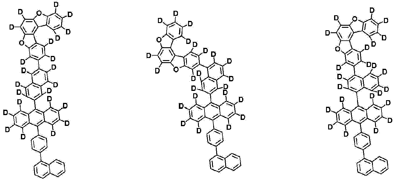


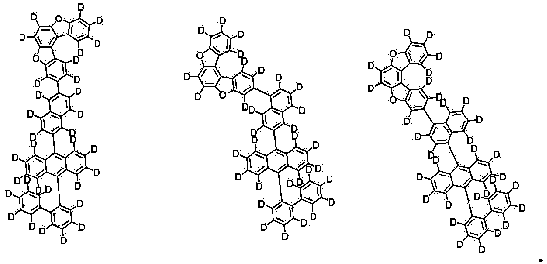
- An organic light emitting device comprising:a first electrode;a second electrode; andan organic material layer having one or more layers provided between the first electrode and the second electrode,wherein one or more layers of the organic material layer comprise the compound of any one of claims 1 to 5.
- The organic light emitting device of claim 6, wherein the organic material layer comprises a hole injection layer, a hole transport layer, or an electron blocking layer, and the hole injection layer, the hole transport layer, or the electron blocking layer comprises the compound.
- The organic light emitting device of claim 6, wherein the organic material layer comprises a light emitting layer, and the light emitting layer comprises the compound.
- The organic light emitting device of claim 6, wherein the organic material layer comprises a light emitting layer, and the light emitting layer comprises the compound as a host of the light emitting layer.
- The organic light emitting device of claim 9, wherein the light emitting layer comprises a dopant, and the dopant comprises one or more selected from the group consisting of a fluorescent dopant, a phosphorescent dopant, and a thermally delayed fluorescent dopant.
- The organic light emitting device of claim 10, wherein the fluorescent dopant comprises one or more selected from the group consisting of an arylamine-based compound and a boron-based compound.
Applications Claiming Priority (2)
| Application Number | Priority Date | Filing Date | Title |
|---|---|---|---|
| KR20210116104 | 2021-09-01 | ||
| PCT/KR2022/008938 WO2023033326A1 (en) | 2021-09-01 | 2022-06-23 | Compound and organic light-emitting element comprising same |
Publications (3)
| Publication Number | Publication Date |
|---|---|
| EP4212535A1 true EP4212535A1 (en) | 2023-07-19 |
| EP4212535A4 EP4212535A4 (en) | 2024-05-22 |
| EP4212535B1 EP4212535B1 (en) | 2025-10-01 |
Family
ID=85411302
Family Applications (1)
| Application Number | Title | Priority Date | Filing Date |
|---|---|---|---|
| EP22864835.8A Active EP4212535B1 (en) | 2021-09-01 | 2022-06-23 | Compound and organic light-emitting element comprising same |
Country Status (7)
| Country | Link |
|---|---|
| US (1) | US20240043412A1 (en) |
| EP (1) | EP4212535B1 (en) |
| JP (1) | JP7604755B2 (en) |
| KR (1) | KR102671135B1 (en) |
| CN (1) | CN116349430A (en) |
| TW (1) | TWI868457B (en) |
| WO (1) | WO2023033326A1 (en) |
Families Citing this family (1)
| Publication number | Priority date | Publication date | Assignee | Title |
|---|---|---|---|---|
| WO2024247860A1 (en) * | 2023-05-31 | 2024-12-05 | 出光興産株式会社 | Compound, organic electroluminescent element, and electronic device |
Family Cites Families (18)
| Publication number | Priority date | Publication date | Assignee | Title |
|---|---|---|---|---|
| KR100430549B1 (en) | 1999-01-27 | 2004-05-10 | 주식회사 엘지화학 | New organomattalic complex molecule for the fabrication of organic light emitting diodes |
| KR101231931B1 (en) * | 2009-11-13 | 2013-02-08 | 주식회사 엘지화학 | New fused cyclic compound and organic electronic device |
| KR101423066B1 (en) * | 2010-09-17 | 2014-07-25 | 롬엔드하스전자재료코리아유한회사 | Novel organic electroluminescent compounds and organic electroluminescent device using the same |
| KR102436175B1 (en) * | 2014-05-09 | 2022-08-26 | 에스에프씨주식회사 | Novel aromatic compounds for organic light-emitting diode and organic light-emitting diode including the same |
| US20160218297A1 (en) * | 2015-01-20 | 2016-07-28 | Samsung Display Co., Ltd. | Organic light-emitting device |
| US10312449B2 (en) * | 2015-05-27 | 2019-06-04 | Samsung Display Co., Ltd. | Organic light-emitting device |
| KR102630643B1 (en) * | 2015-05-27 | 2024-01-31 | 삼성디스플레이 주식회사 | Organic light-emitting device |
| TWI653231B (en) * | 2016-08-09 | 2019-03-11 | 南韓商Lg化學股份有限公司 | Compound and organic light-emitting device comprising the same |
| KR102097870B1 (en) * | 2017-06-16 | 2020-04-07 | 주식회사 엘지화학 | Anthracene derivative and organic light emitting device comprising the same |
| CN114300628A (en) * | 2018-10-10 | 2022-04-08 | 株式会社半导体能源研究所 | Light-emitting device, light-emitting apparatus, electronic apparatus, and lighting apparatus |
| KR20200047400A (en) * | 2018-10-26 | 2020-05-07 | 롬엔드하스전자재료코리아유한회사 | A plurality of light-emitting materials and organic electroluminescent device comprising the same |
| KR102291411B1 (en) * | 2019-12-09 | 2021-08-23 | 엘티소재주식회사 | Heterocyclic compound and organic light emitting device comprising same |
| KR102616373B1 (en) * | 2020-01-20 | 2023-12-20 | 주식회사 엘지화학 | Organic electroluminescent device |
| CN113950754B (en) * | 2020-01-20 | 2024-04-30 | 株式会社Lg化学 | Organic light-emitting devices |
| KR102484034B1 (en) * | 2020-01-20 | 2023-01-04 | 주식회사 엘지화학 | Polycyclic compound and organic light emitting device comprising same |
| CN113841262A (en) * | 2020-01-20 | 2021-12-24 | 株式会社Lg化学 | Organic Light Emitting Devices |
| KR20210094487A (en) * | 2020-01-21 | 2021-07-29 | 주식회사 엘지화학 | Compound and organic light emitting device comprising same |
| KR102455652B1 (en) | 2020-03-17 | 2022-10-18 | 한국전자통신연구원 | Method and apparatus for decoding using soft decision |
-
2022
- 2022-06-23 US US18/028,844 patent/US20240043412A1/en active Pending
- 2022-06-23 KR KR1020220076783A patent/KR102671135B1/en active Active
- 2022-06-23 TW TW111123414A patent/TWI868457B/en active
- 2022-06-23 WO PCT/KR2022/008938 patent/WO2023033326A1/en not_active Ceased
- 2022-06-23 JP JP2023518076A patent/JP7604755B2/en active Active
- 2022-06-23 CN CN202280006758.9A patent/CN116349430A/en active Pending
- 2022-06-23 EP EP22864835.8A patent/EP4212535B1/en active Active
Also Published As
| Publication number | Publication date |
|---|---|
| TWI868457B (en) | 2025-01-01 |
| EP4212535B1 (en) | 2025-10-01 |
| JP2023544109A (en) | 2023-10-20 |
| CN116349430A (en) | 2023-06-27 |
| JP7604755B2 (en) | 2024-12-24 |
| WO2023033326A1 (en) | 2023-03-09 |
| EP4212535A4 (en) | 2024-05-22 |
| US20240043412A1 (en) | 2024-02-08 |
| KR102671135B1 (en) | 2024-05-31 |
| KR20230033573A (en) | 2023-03-08 |
| TW202311264A (en) | 2023-03-16 |
Similar Documents
| Publication | Publication Date | Title |
|---|---|---|
| EP2873667B1 (en) | Heterocyclic compound and organic electronic element containing same | |
| EP3305792B1 (en) | Nitrogen-containing condensed cyclic compound and organic light emitting element using same | |
| EP3439062A1 (en) | Organic light emitting element | |
| KR102741845B1 (en) | Compound and organic light emitting device comprising same | |
| EP4431507A1 (en) | Compound and organic light-emitting device comprising same | |
| EP3263555B1 (en) | Hetero ring compound and organic luminescent element comprising same | |
| KR102732083B1 (en) | Compound, and organic light emitting device comprising same | |
| KR20240150390A (en) | Compound and organic light emitting device comprising same | |
| EP4692277A2 (en) | Compound and organic light-emitting device comprising same | |
| EP4212535B1 (en) | Compound and organic light-emitting element comprising same | |
| EP4431506A1 (en) | Compound and organic light-emitting device comprising same | |
| KR102832006B1 (en) | Compound and organic light emitting device comprising same | |
| KR20230133805A (en) | Compound and organic light emitting device comprising same | |
| KR20230033309A (en) | Compound and organic light emitting device comprising same | |
| KR102865654B1 (en) | Compound and organic light emitting device comprising same | |
| KR102888692B1 (en) | Compound and organic light emitting device comprising same | |
| KR102855164B1 (en) | Compound and organic light emitting device comprising same | |
| KR102817437B1 (en) | Compound and organic light emitting device comprising same | |
| EP4431500A1 (en) | Compound and organic light-emitting device comprising same | |
| KR102888691B1 (en) | Compound and organic light emitting device comprising same | |
| KR102732791B1 (en) | Compound and organic light emitting device comprising same | |
| KR20240150138A (en) | Compound and organic light emitting device comprising same | |
| KR20230055495A (en) | Compound and organic light emitting device comprising same | |
| KR20240162363A (en) | Compound and organic light emitting device comprising same | |
| KR20240150387A (en) | Compound and organic light emitting device comprising same |
Legal Events
| Date | Code | Title | Description |
|---|---|---|---|
| STAA | Information on the status of an ep patent application or granted ep patent |
Free format text: STATUS: THE INTERNATIONAL PUBLICATION HAS BEEN MADE |
|
| PUAI | Public reference made under article 153(3) epc to a published international application that has entered the european phase |
Free format text: ORIGINAL CODE: 0009012 |
|
| STAA | Information on the status of an ep patent application or granted ep patent |
Free format text: STATUS: REQUEST FOR EXAMINATION WAS MADE |
|
| 17P | Request for examination filed |
Effective date: 20230413 |
|
| AK | Designated contracting states |
Kind code of ref document: A1 Designated state(s): AL AT BE BG CH CY CZ DE DK EE ES FI FR GB GR HR HU IE IS IT LI LT LU LV MC MK MT NL NO PL PT RO RS SE SI SK SM TR |
|
| REG | Reference to a national code |
Ref country code: DE Free format text: PREVIOUS MAIN CLASS: C07D0493040000 Ipc: C09K0011060000 Ref country code: DE Ref legal event code: R079 Ref document number: 602022022488 Country of ref document: DE Free format text: PREVIOUS MAIN CLASS: C07D0493040000 Ipc: C09K0011060000 |
|
| A4 | Supplementary search report drawn up and despatched |
Effective date: 20240423 |
|
| RIC1 | Information provided on ipc code assigned before grant |
Ipc: H10K 50/11 20230101ALN20240417BHEP Ipc: H10K 85/60 20230101ALI20240417BHEP Ipc: C07D 493/04 20060101ALI20240417BHEP Ipc: C07B 59/00 20060101ALI20240417BHEP Ipc: C09K 11/06 20060101AFI20240417BHEP |
|
| DAV | Request for validation of the european patent (deleted) | ||
| DAX | Request for extension of the european patent (deleted) | ||
| STAA | Information on the status of an ep patent application or granted ep patent |
Free format text: STATUS: EXAMINATION IS IN PROGRESS |
|
| 17Q | First examination report despatched |
Effective date: 20250102 |
|
| GRAP | Despatch of communication of intention to grant a patent |
Free format text: ORIGINAL CODE: EPIDOSNIGR1 |
|
| STAA | Information on the status of an ep patent application or granted ep patent |
Free format text: STATUS: GRANT OF PATENT IS INTENDED |
|
| RIC1 | Information provided on ipc code assigned before grant |
Ipc: H10K 50/11 20230101ALN20250509BHEP Ipc: H10K 85/60 20230101ALI20250509BHEP Ipc: C07D 493/04 20060101ALI20250509BHEP Ipc: C07B 59/00 20060101ALI20250509BHEP Ipc: C09K 11/06 20060101AFI20250509BHEP |
|
| INTG | Intention to grant announced |
Effective date: 20250523 |
|
| GRAS | Grant fee paid |
Free format text: ORIGINAL CODE: EPIDOSNIGR3 |
|
| GRAA | (expected) grant |
Free format text: ORIGINAL CODE: 0009210 |
|
| STAA | Information on the status of an ep patent application or granted ep patent |
Free format text: STATUS: THE PATENT HAS BEEN GRANTED |
|
| AK | Designated contracting states |
Kind code of ref document: B1 Designated state(s): AL AT BE BG CH CY CZ DE DK EE ES FI FR GB GR HR HU IE IS IT LI LT LU LV MC MK MT NL NO PL PT RO RS SE SI SK SM TR |
|
| REG | Reference to a national code |
Ref country code: GB Ref legal event code: FG4D Ref country code: CH Ref legal event code: F10 Free format text: ST27 STATUS EVENT CODE: U-0-0-F10-F00 (AS PROVIDED BY THE NATIONAL OFFICE) Effective date: 20251001 |
|
| REG | Reference to a national code |
Ref country code: IE Ref legal event code: FG4D |
|
| REG | Reference to a national code |
Ref country code: DE Ref legal event code: R096 Ref document number: 602022022488 Country of ref document: DE |
|
| REG | Reference to a national code |
Ref country code: NL Ref legal event code: MP Effective date: 20251001 |
|
| REG | Reference to a national code |
Ref country code: AT Ref legal event code: MK05 Ref document number: 1842530 Country of ref document: AT Kind code of ref document: T Effective date: 20251001 |
|
| PG25 | Lapsed in a contracting state [announced via postgrant information from national office to epo] |
Ref country code: NL Free format text: LAPSE BECAUSE OF FAILURE TO SUBMIT A TRANSLATION OF THE DESCRIPTION OR TO PAY THE FEE WITHIN THE PRESCRIBED TIME-LIMIT Effective date: 20251001 |
|
| PG25 | Lapsed in a contracting state [announced via postgrant information from national office to epo] |
Ref country code: ES Free format text: LAPSE BECAUSE OF FAILURE TO SUBMIT A TRANSLATION OF THE DESCRIPTION OR TO PAY THE FEE WITHIN THE PRESCRIBED TIME-LIMIT Effective date: 20251001 |
|
| REG | Reference to a national code |
Ref country code: LT Ref legal event code: MG9D |
|
| PG25 | Lapsed in a contracting state [announced via postgrant information from national office to epo] |
Ref country code: NO Free format text: LAPSE BECAUSE OF FAILURE TO SUBMIT A TRANSLATION OF THE DESCRIPTION OR TO PAY THE FEE WITHIN THE PRESCRIBED TIME-LIMIT Effective date: 20260101 |
|
| PG25 | Lapsed in a contracting state [announced via postgrant information from national office to epo] |
Ref country code: AT Free format text: LAPSE BECAUSE OF FAILURE TO SUBMIT A TRANSLATION OF THE DESCRIPTION OR TO PAY THE FEE WITHIN THE PRESCRIBED TIME-LIMIT Effective date: 20251001 Ref country code: FI Free format text: LAPSE BECAUSE OF FAILURE TO SUBMIT A TRANSLATION OF THE DESCRIPTION OR TO PAY THE FEE WITHIN THE PRESCRIBED TIME-LIMIT Effective date: 20251001 Ref country code: HR Free format text: LAPSE BECAUSE OF FAILURE TO SUBMIT A TRANSLATION OF THE DESCRIPTION OR TO PAY THE FEE WITHIN THE PRESCRIBED TIME-LIMIT Effective date: 20251001 |
|
| PG25 | Lapsed in a contracting state [announced via postgrant information from national office to epo] |
Ref country code: RS Free format text: LAPSE BECAUSE OF FAILURE TO SUBMIT A TRANSLATION OF THE DESCRIPTION OR TO PAY THE FEE WITHIN THE PRESCRIBED TIME-LIMIT Effective date: 20260101 |
|
| PG25 | Lapsed in a contracting state [announced via postgrant information from national office to epo] |
Ref country code: IS Free format text: LAPSE BECAUSE OF FAILURE TO SUBMIT A TRANSLATION OF THE DESCRIPTION OR TO PAY THE FEE WITHIN THE PRESCRIBED TIME-LIMIT Effective date: 20260201 |
|
| PG25 | Lapsed in a contracting state [announced via postgrant information from national office to epo] |
Ref country code: CZ Free format text: LAPSE BECAUSE OF FAILURE TO SUBMIT A TRANSLATION OF THE DESCRIPTION OR TO PAY THE FEE WITHIN THE PRESCRIBED TIME-LIMIT Effective date: 20251001 Ref country code: PT Free format text: LAPSE BECAUSE OF FAILURE TO SUBMIT A TRANSLATION OF THE DESCRIPTION OR TO PAY THE FEE WITHIN THE PRESCRIBED TIME-LIMIT Effective date: 20260202 |
|
| PG25 | Lapsed in a contracting state [announced via postgrant information from national office to epo] |
Ref country code: PL Free format text: LAPSE BECAUSE OF FAILURE TO SUBMIT A TRANSLATION OF THE DESCRIPTION OR TO PAY THE FEE WITHIN THE PRESCRIBED TIME-LIMIT Effective date: 20251001 |
|
| PG25 | Lapsed in a contracting state [announced via postgrant information from national office to epo] |
Ref country code: LV Free format text: LAPSE BECAUSE OF FAILURE TO SUBMIT A TRANSLATION OF THE DESCRIPTION OR TO PAY THE FEE WITHIN THE PRESCRIBED TIME-LIMIT Effective date: 20251001 |
|
| PG25 | Lapsed in a contracting state [announced via postgrant information from national office to epo] |
Ref country code: BG Free format text: LAPSE BECAUSE OF FAILURE TO SUBMIT A TRANSLATION OF THE DESCRIPTION OR TO PAY THE FEE WITHIN THE PRESCRIBED TIME-LIMIT Effective date: 20251001 |