EP4212464A1 - One-sheet picking device - Google Patents
One-sheet picking device Download PDFInfo
- Publication number
- EP4212464A1 EP4212464A1 EP21866715.2A EP21866715A EP4212464A1 EP 4212464 A1 EP4212464 A1 EP 4212464A1 EP 21866715 A EP21866715 A EP 21866715A EP 4212464 A1 EP4212464 A1 EP 4212464A1
- Authority
- EP
- European Patent Office
- Prior art keywords
- workpiece
- separation unit
- loading area
- uppermost
- uppermost workpiece
- Prior art date
- Legal status (The legal status is an assumption and is not a legal conclusion. Google has not performed a legal analysis and makes no representation as to the accuracy of the status listed.)
- Granted
Links
Images


Classifications
-
- B—PERFORMING OPERATIONS; TRANSPORTING
- B65—CONVEYING; PACKING; STORING; HANDLING THIN OR FILAMENTARY MATERIAL
- B65H—HANDLING THIN OR FILAMENTARY MATERIAL, e.g. SHEETS, WEBS, CABLES
- B65H3/00—Separating articles from piles
- B65H3/08—Separating articles from piles using pneumatic force
- B65H3/0808—Suction grippers
- B65H3/0816—Suction grippers separating from the top of pile
-
- B—PERFORMING OPERATIONS; TRANSPORTING
- B21—MECHANICAL METAL-WORKING WITHOUT ESSENTIALLY REMOVING MATERIAL; PUNCHING METAL
- B21D—WORKING OR PROCESSING OF SHEET METAL OR METAL TUBES, RODS OR PROFILES WITHOUT ESSENTIALLY REMOVING MATERIAL; PUNCHING METAL
- B21D43/00—Feeding, positioning or storing devices combined with, or arranged in, or specially adapted for use in connection with, apparatus for working or processing sheet metal, metal tubes or metal profiles; Associations therewith of cutting devices
- B21D43/20—Storage arrangements; Piling or unpiling
- B21D43/24—Devices for removing sheets from a stack
-
- B—PERFORMING OPERATIONS; TRANSPORTING
- B65—CONVEYING; PACKING; STORING; HANDLING THIN OR FILAMENTARY MATERIAL
- B65H—HANDLING THIN OR FILAMENTARY MATERIAL, e.g. SHEETS, WEBS, CABLES
- B65H3/00—Separating articles from piles
- B65H3/08—Separating articles from piles using pneumatic force
- B65H3/0808—Suction grippers
- B65H3/0816—Suction grippers separating from the top of pile
- B65H3/0833—Suction grippers separating from the top of pile and acting on the front part of the articles relatively to the final separating direction
-
- B—PERFORMING OPERATIONS; TRANSPORTING
- B65—CONVEYING; PACKING; STORING; HANDLING THIN OR FILAMENTARY MATERIAL
- B65H—HANDLING THIN OR FILAMENTARY MATERIAL, e.g. SHEETS, WEBS, CABLES
- B65H3/00—Separating articles from piles
- B65H3/46—Supplementary devices or measures to assist separation or prevent double feed
- B65H3/48—Air blast acting on edges of, or under, articles
-
- B—PERFORMING OPERATIONS; TRANSPORTING
- B65—CONVEYING; PACKING; STORING; HANDLING THIN OR FILAMENTARY MATERIAL
- B65H—HANDLING THIN OR FILAMENTARY MATERIAL, e.g. SHEETS, WEBS, CABLES
- B65H2701/00—Handled material; Storage means
- B65H2701/10—Handled articles or webs
- B65H2701/17—Nature of material
- B65H2701/173—Metal
Definitions
- the present invention relates to a single-sheet lifter for lifting a single sheet of an uppermost workpiece among a plurality of the workpieces (sheet metals) loaded in a loading area.
- a magnet floater installed in a vicinity of the loading area.
- the magnet floater makes it easier to separate the uppermost workpiece by levitating, with a magnetic force, several upper workpieces among the plurality of workpieces loaded in the loading area (see Patent Literature 1 described below).
- the workpiece is a non-magnetic body, it is not possible to levitate the workpieces with the magnetic force, and it is difficult to separate only the uppermost workpiece by a workpiece suction lifter of the loading machine.
- the air separator installed in the vicinity of the loading area may be used.
- the air separator separates the uppermost workpiece among the plurality of workpieces loaded in the loading area with a jet pressure of air (see Patent Literature 2 described below).
- the air separator includes a base frame installed in the vicinity of the loading area and extending vertically, and a separation unit provided to the base frame so as to be able to move up and down.
- the uppermost workpiece is separated from other workpieces by the pressure of the air injected from the separation unit.
- the separation unit includes a contact member that comes into contact with the surface of the uppermost workpiece and a nozzle for injecting the air toward the edge of the uppermost workpiece.
- the separation unit When the workpiece suction lifter of the loading machine sucks the surface of the uppermost workpiece to lift the workpiece, the separation unit goes up following the lifting operation of the workpiece suction lifter and is retracted from above the loading area. When the separation unit retracted from above the loading area falls due to its own weight, the separation unit returns to a position above the plurality of workpieces loaded in the loading area.
- Patent Literature 3 described below also discloses a technique related to the present invention.
- Patent Literature 3 relates to an improvement of the workpiece suction lifter.
- the weight of the separation unit becomes large. If the weight of the separation unit is large, the workpiece loaded in the loading area may be scratched due to the impact when the separation unit falls. Further, if the rigidity of the workpiece is small, the vicinity of the edge of the workpiece may be deflected and plastically deformed by the pressure of the air when the workpiece suction lifter lifts the uppermost workpiece. Regarding the air separator, an improvement is desired in stably lifting the uppermost workpiece while preventing the workpiece from being damaged.
- An object of the present invention is to provide a single-sheet lifter capable of stably lifting the uppermost workpiece while preventing the workpiece from being damaged.
- a single-sheet lifter including a base frame arranged in a vicinity of a loading area and extending vertically, a separation unit provided to the base frame so as to be able to move up and down (move vertically), the separation unit including a contact member that comes into contact with a surface of an uppermost workpiece among a plurality of the workpieces loaded in the loading area, the separation unit being configured to go up following a lifting operation (an ascending operation) of a workpiece suction lifter of a loading machine and be retracted from above the loading area when the workpiece suction lifter sucks the surface of the uppermost workpiece to lift the workpiece, and configured to separate the uppermost workpiece from other workpieces by means of at least one of an injection pressure of air and a suction force, and a counter balancer configured to reduce a weight acting on the separation unit.
- the single-sheet lifter may further include a first rotating wheel provided to the base frame so as to be able to rotate, a second rotating wheel provided to the base frame so as to be able to rotate and move up and down, and a linear or band-shaped connecting member including one end connected to the separation unit and another end connected to the base frame, the connecting member being hung around the first rotating wheel, and hung around the second rotating wheel so as to suspend the second rotating wheel.
- the counter balancer is configured to apply a downward force to the second rotating wheel.
- the separation unit may include a bellows type suction pad for sucking a surface in a vicinity of an edge of the uppermost workpiece.
- the separation unit is configured to lift up the edge of the uppermost workpiece using the contact member as a fulcrum when the suction pad executes a sucking operation in a state in which the contact member is in contact with the surface of the uppermost workpiece.
- the separation unit may include a nozzle for injecting the air toward the edge of the uppermost workpiece.
- the single-sheet lifter may further include an assist unit for assisting a falling operation (a descending operation) due to an own weight of the separation unit that is retracted from the upper side of the loading area.
- the contact member may be a contact roller rotatable around a horizontal axial center of rotation.
- a “loading area” refers to a three-dimensional area for loading a plurality of workpieces (sheet metals).
- "FF”, “FR”, “L”, “R”, “U”, and “D” in the drawings refer to a forward direction, a backward direction, a left direction, a right direction, an upper direction, and a downward direction, respectively.
- the single-sheet lifter 10 is a machine for lifting only an uppermost workpiece W among a plurality of the plate-shaped workpieces W loaded on a pallet P placed in a loading area TA.
- the single-sheet lifter 10 is installed on an L-shaped installation table 12 in a plan view provided in a vicinity of the loading area TA, and is located on the right side of the loading area TA.
- the single-sheet lifter 10 is a kind of air separator that separates the uppermost workpiece W by means of an injection pressure of air.
- the single-sheet lifter 10 is used when the plurality of workpieces W loaded on the pallet P in the loading area TA are sequentially supplied to a press brake (not shown) by a supply robot 14.
- the supply robot 14 is a kind of loading machine that supplies the workpieces W to the press brake.
- the supply robot 14 has, for example, the configuration disclosed in Patent Literature 3.
- the supply robot 14 includes an articulated robot arm 16 and a robot hand 18 as a workpiece suction lifter for sucking the workpiece W, which is attached to the tip of the robot arm 16.
- the press brake is a working machine that bends the workpiece W, and is installed behind the loading area TA.
- On the right side of the loading area TA in addition to the single-sheet lifter 10, a double-sheet lifting detection machine (not shown) is also installed. The double-sheet lifting detection machine detects whether or not the robot hand 18 has sucked two or more workpieces W.
- the single-sheet lifter 10 includes a base frame 20 arranged on the installation table 12.
- the base frame 20 extends vertically.
- the base frame 20 includes a pair of support plates 22 that are separated and opposed to each other in the front-rear direction, and a plurality of spacers 24 that connect the two support plates 22.
- a first guide elongated hole 22h extending vertically is formed on each of the support plates 22.
- the upper portion of the first guide elongated hole 22h is curved so as to be away from the loading area TA.
- a second guide elongated hole 22v extending vertically is formed on the right side of the first guide elongated hole 22h.
- a separation unit 26 that separates the uppermost workpiece W from other workpieces W by means of the injection pressure of air and the suction force is provided to the base frame 20 so as to be able to move up and down (move vertically).
- the specific configuration of the separation unit 26 will be described below.
- the separation unit 26 includes a unit main body 28 provided to the base frame 20 so as to be able to move up and down.
- the unit main body 28 projects in a cantilevered manner with respect to the base frame 20.
- two pairs of guide rollers 30 with flanges are rotatably provided around a horizontal axial center of rotation thereof.
- the guide rollers 30 in each of the pair are separated and opposed to each other in the front-rear direction.
- Each of the guide roller 30 is guided and supported by the first guide elongated hole 22h.
- a contact roller 32 as a contact member that comes into contact with the surface of the uppermost workpiece W from above is provided via a pair of brackets 34.
- the contact roller 32 is rotatable around a horizontal axial center of rotation thereof, and is made of an elastic material such as urethane.
- a nozzle 36 for injecting air toward an edge of the uppermost workpiece W is provided in a vicinity of the base end of the unit main body 28.
- the nozzle 36 is connected to an air supplying source (not shown) such as a supply pump that supplies the air.
- a bellows type suction pad 38 for sucking a surface in a vicinity of the edge of the uppermost workpiece W from above is provided in the middle part of the unit main body 28.
- the suction pad 38 is connected to an air suctioning source (not shown) such as a vacuum pump for sucking air.
- the suction pad 38 comes into contact with the surface of the uppermost workpiece W prior to the contact roller 32.
- the separation unit 26 is configured to lift up the edge of the uppermost workpiece W using the contact roller 32 as a fulcrum when the suction pad 38 executes a sucking operation in a state in which the contact roller 32 is in contact with the surface of the uppermost workpiece W (see Figure 7A ).
- the separation unit 26 is configured to go up following a lifting operation (an ascending operation) of the robot hand 18 and be retracted from above the loading area TA when the robot hand 18 lifts the uppermost workpiece W. Further, when the separation unit 26 retracted from above the loading area TA falls due to its own weight, the separation unit 26 returns to the position above the plurality of workpieces W loaded in the loading area TA via the pallet P.
- a lifting operation an ascending operation
- the separation unit 26 separates the uppermost workpiece W from the other workpieces W by means of either the injection pressure of the air or the suction force.
- a first sprocket 40 as a rotating wheel is rotatably provided around a horizontal axial center of rotation thereof.
- Each end portion of a rotating shaft 42 of the first sprocket 40 is rotatably supported at the upper part of the support plate 22 via a support ring 44.
- the first sprocket 40 is not able to move up and down with respect to the support plate 22.
- a second sprocket 46 as a second rotating wheel is provided so as to be able to move up and down, and rotate around a horizontal axial center of rotation thereof.
- Each end portion of a rotating shaft 48 of the second sprocket 46 is supported by the second guide elongated hole 22v of the support plate 22 so as to be able to rotate and move up and down.
- a connecting chain 50 as a linear connecting member is provided between the pair of support plates 22.
- One end of the connecting chain 50 is connected to the base end of the separation unit 26.
- the other end of the connecting chain 50 is connected to the upper right portion of the base frame 20.
- the vicinity of the one end of the connecting chain 50 is hung around the first sprocket 40.
- the vicinity of the other end of the connecting chain 50 is hung around the second sprocket 46 so as to suspend the second sprocket 46.
- a first pulley (not shown) and a second pulley (not shown) may be used as the first and second rotating wheels, respectively.
- a connecting belt (not shown) is used as a band-shaped connecting member.
- a counter balancer 52 that reduces a weight acting on the separation unit 26 is provided at each end portion of the rotating shaft 48 of the second sprocket 46.
- Each of the counter balancers 52 includes a plurality of weights 54 that apply gravity as a downward force to the second sprocket 46.
- the counter balancer 52 is configured to be nonrotatable with respect to the support plate 22. That is, the counter balancer 52 is configured to be rotatable relative to the rotating shaft 48 of the second sprocket 46.
- a coil spring (not shown) that applies an urging force as the downward force to the second sprocket 46 may be used.
- the coil spring is provided between each end portion of the rotating shaft 48 of the second sprocket 46 and the support plate 22.
- the single-sheet lifter 10 includes an assist unit 56 for assisting a falling operation (a descending operation) due to the own weight of the separation unit 26 that is retracted from above the loading area TA.
- the specific configuration of the assist unit 56 will be described below.
- the base end of a swing lever 58 is integrally connected to one end of the rotating shaft 42 of the first sprocket 40.
- An air cylinder 60 as an assist actuator is attached via a bracket 62 to the support plate 22 on the front side.
- the air cylinder 60 includes an operation rod 64 that can move vertically.
- the assist unit 56 is configured such that the air cylinder 60 is driven to cause the operation rod 64 to push the tip of the swing lever 58 from below, which is applied to the first sprocket 40 for promoting the falling operation of the separation unit 26.
- the separation unit 26 is also caused to go up following the lifting operation of the robot hand 18, and is guided by the first guide elongated hole 22h and retracted from above the loading area TA. As a result of this, the workpiece W sucked by the robot hand 18 of the supply robot 14 is supplied to the press brake without being hindered by the separation unit 26.
- the air cylinder 60 is driven to cause the operation rod 64 to press the tip of the swing lever 58 from below, as shown in Figure 7C .
- a rotational force that promotes the falling operation of the separation unit 26 is applied to the first sprocket 40.
- the separation unit 26 falls due to its own weight and returns to the position above the plurality of workpieces W loaded in the loading area TA.
- the plurality of workpieces W loaded in the loading area TA can be sequentially supplied to the press brake by the supply robot 14.
- the separation unit 26 is configured to lift up the edge of the uppermost workpiece W using the contact roller 32 as a fulcrum when the suction pad 38 executes the sucking operation in a state in which the contact roller 32 is in contact with the surface of the uppermost workpiece W. This makes it possible for the uppermost workpiece W to be easily separated from the other workpieces W. As a result, it is possible for the robot hand 18 to reliably lift only the uppermost workpiece W.
- the separation unit 26 separates the uppermost workpiece W from the other workpieces W by way of the injection pressure of the air and the suction force. Therefore, even when the workpiece W is a non-magnetic body, it is possible for the robot hand 18 to lift only the uppermost workpiece W. In other words, regardless of the material of the workpiece W, it is possible for the robot hand 18 to lift only the uppermost workpiece W.
- the one end of the connecting chain 50 is connected to the base end of the separation unit 26, and the other end of the connecting chain 50 is connected to the upper right side of the base frame 20.
- the vicinity of the one end of the connecting chain 50 is hung around the first sprocket 40.
- the vicinity of the other end of the connecting chain 50 is hung around the second sprocket 46 so as to suspend the second sprocket 46.
- the counter balancer 52 that reduces the weight acting on the separation unit 26 is provided at each of the end portions of the rotating shaft 48 of the second sprocket 46.
- the weight of the separation unit 26 is large and the rigidity of the workpiece W is small, it is possible to support the separation unit 26 sufficiently from below without plastically deforming the vicinity of the edge of the workpiece W when the uppermost workpiece W is lifted. Further, even if the weight of the separation unit 26 is large, the impact when the separation unit 26 falls can be sufficiently reduced to prevent the workpieces W loaded in the loading area TA from being scratched.
- the robot hand 18 regardless of the material of the workpiece W, it is possible for the robot hand 18 to stably lift only the uppermost workpiece W without damaging the workpiece W.
- the assist unit 56 assists the falling operation due to the own weight of the separation unit 26, it is possible to reliably return the separation unit 26 to the position above the plurality of workpieces W loaded in the loading area TA. Further, since the contact roller 32 is rotatable around the horizontal axial center of rotation thereof, even if the end portion of the workpiece W interferes with the contact roller 32 when the workpiece W is lifted by the robot hand 18, the contact roller 32 does not hinder the workpiece W from being lifted.
- the supply robot 14 it is possible for the supply robot 14 to sequentially and stably supply, to the press brake, the plurality of workpieces W loaded in the loading area TA.
- a single-sheet lifter 10A is a machine for lifting only the uppermost workpiece W among the plurality of the workpieces W loaded on the pallet P placed in the loading area TA, in the same manner as the single-sheet lifter 10 described above (see Figure 3 ).
- the single-sheet lifter 10A includes an assist unit 66 having a configuration different from that of the assist unit 56 (see Figure 3 ).
- Other configurations are the same as those of the single-sheet lifter 10.
- the specific configuration of the assist unit 66 will be described below.
- the same reference numerals will be given to the components that are the same as or equivalent to those of the single-sheet lifter 10 described above, and a detailed description thereof will be omitted.
- An L-shaped operating link 68 is provided above the second guide elongated hole 22v in the support plate 22 on the front side so as to be swingable around a horizontal axial center of swinging (an axial center of a swinging shaft 70).
- an air cylinder 72 as an assist actuator is attached to the support plate 22 via a bracket 74.
- the air cylinder 72 includes an operation rod 76 that can move vertically.
- a rotatable connecting pin 78 is attached to the tip of the operation rod 76.
- the connecting pin 78 is connected to an elongated hole (not shown) formed at a first tip (one end) of the operating link 68.
- the assist unit 66 is configured such that a rotational force that promotes the falling operation of the separation unit 26 is applied to the unit main body 28 when the air cylinder 72 is driven to cause a second tip (the other end) of the operating link 68 to push the unit main body 28 from the right side.
- the separation unit 26 is configured to go up following the lifting operation of the robot hand 18 and be retracted from above the loading area TA when the robot hand 18 (the workpiece suction lifter) of the supply robot 14 (the loading machine) sucks the surface of the uppermost workpiece W to lift the workpiece W. For this reason, the workpiece W sucked by the robot hand 18 of the supply robot 14 can be supplied to the press brake without being hindered by the separation unit 26. Since the separation unit 26 does not hinder the workpiece W from moving, it is possible to prevent the workpiece W from being damaged.
- the separation unit 26 includes the contact roller 32 (the contact member) that comes into contact with the surface of the uppermost workpiece W. For this reason, when the uppermost workpiece W is separated by means of at least one of the injection pressure of the air and the suction force, separation from the other workpieces W by lifting up the edge of the uppermost workpiece W can be easier. As a result, it is possible to reliably and stably lift only the upper workpiece W.
- the uppermost workpiece W is separated by means of at least one of the injection pressure of the air and the suction force, it is possible to reliably and stably lift only the uppermost workpiece W even when the workpiece W is a non-magnetic body, that is, when it is made of any raw material.
- the single-sheet lifter 10 (10A) also includes the counter balancer 52 that reduces the weight acting on the separation unit 26. For this reason, when the workpiece W is lifted by the robot hand 18, the weight of the separation unit 26 acting on the workpiece W can be alleviated by the counter balancer 52, and the deformation of the low-rigid workpiece W can be prevented. At the same time, the retracting operation of the separation unit 26 as the workpiece W goes up can be performed smoothly. Further, when the retracted separation unit 26 is caused to fall and return above the loaded workpieces W, the falling operation can be alleviated by the counter balancer 52. As a result, it is possible to prevent the workpiece W from being damaged.
- the single-sheet lifter 10 (10A) further include the first sprocket 40 (the first rotating wheel) and the second sprocket 46 (the second rotating wheel), and the linear connecting chain 50 (the connecting member) that are described above.
- the connecting chain 50 is hung around the first sprocket 40 and the second sprocket 46, the second sprocket 46 is suspended by the connecting chain 50, and the counter balancer 52 applies the downward force to the second sprocket 46.
- the weight of the separation unit 26 can be effectively reduced by the downward force applied to the second sprocket 46.
- the first pulley may be used as the first rotating wheel
- the second pulley may be used as the second rotating wheel
- the band-shaped connecting belt may be used as the connecting member.
- the separation unit 26 includes the bellows type suction pad 38 for sucking the surface in the vicinity of the edge of the uppermost workpiece W. For this reason, when the suction pad 38 is operated in a state in which the contact roller 32 (the contact member) is in contact with the surface of the uppermost workpiece W, it is possible to lift up the edge of the uppermost workpiece W using the contact roller 32 as a fulcrum. That is, it is possible to separate the uppermost workpiece W more reliably.
- the separation unit 26 includes the nozzle 36 for injecting the air toward the edge of the uppermost workpiece W. For this reason, by injecting the air from the nozzle 36, it is possible to lift up the edge of the uppermost workpiece W, using the contact roller 32 as a fulcrum, by means of the injection pressure thereof. That is, it is possible to separate the uppermost workpiece W more reliably.
- the single-sheet lifter 10 (10A) according to the embodiment and modified example described above further include the assist unit 56 (66) for assisting the falling operation due to the own weight of the retracted separation unit 26. For this reason, it is possible to return the separation unit 26 above the loaded workpieces W easily and quickly.
- the contact member is the contact roller 32 that is rotatable around the horizontal axial center of rotation.
- the contact roller 32 rotates so that the workpiece W is away from the contact roller 32 with the movement thereof not being hindered. Therefore, it is possible to prevent the workpiece W from being damaged, and the supply of the workpieces W is not hindered.
- the present invention is not limited to the embodiment and modified example described above.
- the uppermost workpiece W is separated from the other workpieces W by using both the injection pressure of the air and the suction force.
- only at least one of the injection pressure of the air (the nozzle 36) and the suction force (the suction pad 38) may be used.
- an assist unit including an electric motor or a belt mechanism may be used. In this case, the assist unit assists the falling operation due to the own weight of the separation unit 26 by driving the electric motor or the belt mechanism.
Landscapes
- Engineering & Computer Science (AREA)
- Mechanical Engineering (AREA)
- Sheets, Magazines, And Separation Thereof (AREA)
- Manipulator (AREA)
- Chemical & Material Sciences (AREA)
- Dispersion Chemistry (AREA)
- Robotics (AREA)
Abstract
Description
- The present invention relates to a single-sheet lifter for lifting a single sheet of an uppermost workpiece among a plurality of the workpieces (sheet metals) loaded in a loading area.
- When a plurality of workpieces loaded in a loading area are sequentially supplied to a working machine such as a press brake by a loading machine such as a supply robot, a magnet floater installed in a vicinity of the loading area is used. The magnet floater makes it easier to separate the uppermost workpiece by levitating, with a magnetic force, several upper workpieces among the plurality of workpieces loaded in the loading area (see Patent Literature 1 described below). When the workpiece is a non-magnetic body, it is not possible to levitate the workpieces with the magnetic force, and it is difficult to separate only the uppermost workpiece by a workpiece suction lifter of the loading machine.
- An air separator installed in the vicinity of the loading area may be used. The air separator separates the uppermost workpiece among the plurality of workpieces loaded in the loading area with a jet pressure of air (see Patent Literature 2 described below). The air separator includes a base frame installed in the vicinity of the loading area and extending vertically, and a separation unit provided to the base frame so as to be able to move up and down. The uppermost workpiece is separated from other workpieces by the pressure of the air injected from the separation unit. The separation unit includes a contact member that comes into contact with the surface of the uppermost workpiece and a nozzle for injecting the air toward the edge of the uppermost workpiece. When the workpiece suction lifter of the loading machine sucks the surface of the uppermost workpiece to lift the workpiece, the separation unit goes up following the lifting operation of the workpiece suction lifter and is retracted from above the loading area. When the separation unit retracted from above the loading area falls due to its own weight, the separation unit returns to a position above the plurality of workpieces loaded in the loading area.
- Note that in addition to Patent Literatures 1 and 2, Patent Literature 3 described below also discloses a technique related to the present invention. Patent Literature 3 relates to an improvement of the workpiece suction lifter.
-
- Patent Literature 1:
Japanese Patent Application Laid-Open Publication No. 2016-112608 - Patent Literature 2:
Japanese Patent Application Laid-Open Publication No. 2017-149496 - Patent Literature 3:
Japanese Patent Application Laid-Open Publication No. 2017-124469 - If the air separator is used, the weight of the separation unit becomes large. If the weight of the separation unit is large, the workpiece loaded in the loading area may be scratched due to the impact when the separation unit falls. Further, if the rigidity of the workpiece is small, the vicinity of the edge of the workpiece may be deflected and plastically deformed by the pressure of the air when the workpiece suction lifter lifts the uppermost workpiece. Regarding the air separator, an improvement is desired in stably lifting the uppermost workpiece while preventing the workpiece from being damaged.
- An object of the present invention is to provide a single-sheet lifter capable of stably lifting the uppermost workpiece while preventing the workpiece from being damaged.
- According to one aspect of the present invention, there is provided a single-sheet lifter including a base frame arranged in a vicinity of a loading area and extending vertically, a separation unit provided to the base frame so as to be able to move up and down (move vertically), the separation unit including a contact member that comes into contact with a surface of an uppermost workpiece among a plurality of the workpieces loaded in the loading area, the separation unit being configured to go up following a lifting operation (an ascending operation) of a workpiece suction lifter of a loading machine and be retracted from above the loading area when the workpiece suction lifter sucks the surface of the uppermost workpiece to lift the workpiece, and configured to separate the uppermost workpiece from other workpieces by means of at least one of an injection pressure of air and a suction force, and a counter balancer configured to reduce a weight acting on the separation unit.
- The single-sheet lifter may further include a first rotating wheel provided to the base frame so as to be able to rotate, a second rotating wheel provided to the base frame so as to be able to rotate and move up and down, and a linear or band-shaped connecting member including one end connected to the separation unit and another end connected to the base frame, the connecting member being hung around the first rotating wheel, and hung around the second rotating wheel so as to suspend the second rotating wheel. In this case, the counter balancer is configured to apply a downward force to the second rotating wheel.
- The separation unit may include a bellows type suction pad for sucking a surface in a vicinity of an edge of the uppermost workpiece. In this case, the separation unit is configured to lift up the edge of the uppermost workpiece using the contact member as a fulcrum when the suction pad executes a sucking operation in a state in which the contact member is in contact with the surface of the uppermost workpiece. Further, the separation unit may include a nozzle for injecting the air toward the edge of the uppermost workpiece.
- The single-sheet lifter may further include an assist unit for assisting a falling operation (a descending operation) due to an own weight of the separation unit that is retracted from the upper side of the loading area. Further, the contact member may be a contact roller rotatable around a horizontal axial center of rotation.
-
- [
Figure 1] Figure 1 is a front view in a vicinity of a loading area including a single-sheet lifter according to the present embodiment. - [
Figure 2] Figure 2 is a plan view in the vicinity of the loading area described above. - [
Figure 3] Figure 3 is a front view of the single-sheet lifter described above. - [
Figure 4] Figure 4 is a left side view of the single-sheet lifter described above. - [
Figure 5] Figure 5 is a rear view of the single-sheet lifter described above. - [
Figure 6] Figure 6 is a plan view of the single-sheet lifter described above. - [
Figure 7A] Figure 7A is a diagram illustrating an operation of the single-sheet lifter described above (a state in which an edge of a workpiece at the top part is being lifted up). - [
Figure 7B] Figure 7B is a diagram illustrating an operation of the single-sheet lifter described above (a state in which a separation unit is retracted from above the loading area). - [
Figure 7C] Figure 7C is a diagram illustrating an operation of the single-sheet lifter described above (a state in which an operation rod presses a tip of a swing lever from below). - [
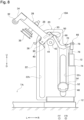
Figure 8] Figure 8 is a front view of a single-sheet lifter according to a modified example (a state in which a second distal end of an operating link presses a unit main body from the right side). - Hereinafter, a single-
sheet lifter 10 according to an embodiment will be described with reference to the drawings. - A "loading area" refers to a three-dimensional area for loading a plurality of workpieces (sheet metals). "FF", "FR", "L", "R", "U", and "D" in the drawings refer to a forward direction, a backward direction, a left direction, a right direction, an upper direction, and a downward direction, respectively.
- As shown in
Figures 1 and2 , the single-sheet lifter 10 is a machine for lifting only an uppermost workpiece W among a plurality of the plate-shaped workpieces W loaded on a pallet P placed in a loading area TA. The single-sheet lifter 10 is installed on an L-shaped installation table 12 in a plan view provided in a vicinity of the loading area TA, and is located on the right side of the loading area TA. The single-sheet lifter 10 is a kind of air separator that separates the uppermost workpiece W by means of an injection pressure of air. The single-sheet lifter 10 is used when the plurality of workpieces W loaded on the pallet P in the loading area TA are sequentially supplied to a press brake (not shown) by asupply robot 14. - The
supply robot 14 is a kind of loading machine that supplies the workpieces W to the press brake. Thesupply robot 14 has, for example, the configuration disclosed in Patent Literature 3. Thesupply robot 14 includes anarticulated robot arm 16 and arobot hand 18 as a workpiece suction lifter for sucking the workpiece W, which is attached to the tip of therobot arm 16. The press brake is a working machine that bends the workpiece W, and is installed behind the loading area TA. On the right side of the loading area TA, in addition to the single-sheet lifter 10, a double-sheet lifting detection machine (not shown) is also installed. The double-sheet lifting detection machine detects whether or not therobot hand 18 has sucked two or more workpieces W. - As shown in
Figures 3 to 6 , the single-sheet lifter 10 includes abase frame 20 arranged on the installation table 12. Thebase frame 20 extends vertically. Thebase frame 20 includes a pair ofsupport plates 22 that are separated and opposed to each other in the front-rear direction, and a plurality ofspacers 24 that connect the twosupport plates 22. A first guideelongated hole 22h extending vertically is formed on each of thesupport plates 22. The upper portion of the first guideelongated hole 22h is curved so as to be away from the loading area TA. A second guideelongated hole 22v extending vertically is formed on the right side of the first guideelongated hole 22h. - A
separation unit 26 that separates the uppermost workpiece W from other workpieces W by means of the injection pressure of air and the suction force is provided to thebase frame 20 so as to be able to move up and down (move vertically). The specific configuration of theseparation unit 26 will be described below. - The
separation unit 26 includes a unitmain body 28 provided to thebase frame 20 so as to be able to move up and down. The unitmain body 28 projects in a cantilevered manner with respect to thebase frame 20. At the base end of the unitmain body 28, two pairs ofguide rollers 30 with flanges are rotatably provided around a horizontal axial center of rotation thereof. Theguide rollers 30 in each of the pair are separated and opposed to each other in the front-rear direction. Each of theguide roller 30 is guided and supported by the first guide elongatedhole 22h. - At the tip of the unit
main body 28, acontact roller 32 as a contact member that comes into contact with the surface of the uppermost workpiece W from above is provided via a pair ofbrackets 34. Thecontact roller 32 is rotatable around a horizontal axial center of rotation thereof, and is made of an elastic material such as urethane. Anozzle 36 for injecting air toward an edge of the uppermost workpiece W is provided in a vicinity of the base end of the unitmain body 28. Thenozzle 36 is connected to an air supplying source (not shown) such as a supply pump that supplies the air. - A bellows
type suction pad 38 for sucking a surface in a vicinity of the edge of the uppermost workpiece W from above is provided in the middle part of the unitmain body 28. Thesuction pad 38 is connected to an air suctioning source (not shown) such as a vacuum pump for sucking air. Thesuction pad 38 comes into contact with the surface of the uppermost workpiece W prior to thecontact roller 32. Theseparation unit 26 is configured to lift up the edge of the uppermost workpiece W using thecontact roller 32 as a fulcrum when thesuction pad 38 executes a sucking operation in a state in which thecontact roller 32 is in contact with the surface of the uppermost workpiece W (seeFigure 7A ). - The
separation unit 26 is configured to go up following a lifting operation (an ascending operation) of therobot hand 18 and be retracted from above the loading area TA when therobot hand 18 lifts the uppermost workpiece W. Further, when theseparation unit 26 retracted from above the loading area TA falls due to its own weight, theseparation unit 26 returns to the position above the plurality of workpieces W loaded in the loading area TA via the pallet P. - Note that either the
nozzle 36 or thesuction pad 38 may be omitted from theseparation unit 26. In this case, theseparation unit 26 separates the uppermost workpiece W from the other workpieces W by means of either the injection pressure of the air or the suction force. - At the upper part between the pair of
support plates 22, afirst sprocket 40 as a rotating wheel is rotatably provided around a horizontal axial center of rotation thereof. Each end portion of arotating shaft 42 of thefirst sprocket 40 is rotatably supported at the upper part of thesupport plate 22 via asupport ring 44. Thefirst sprocket 40 is not able to move up and down with respect to thesupport plate 22. Further, on the right side of thefirst sprocket 40 in thebase frame 20, asecond sprocket 46 as a second rotating wheel is provided so as to be able to move up and down, and rotate around a horizontal axial center of rotation thereof. Each end portion of arotating shaft 48 of thesecond sprocket 46 is supported by the second guide elongatedhole 22v of thesupport plate 22 so as to be able to rotate and move up and down. - A connecting
chain 50 as a linear connecting member is provided between the pair ofsupport plates 22. One end of the connectingchain 50 is connected to the base end of theseparation unit 26. The other end of the connectingchain 50 is connected to the upper right portion of thebase frame 20. The vicinity of the one end of the connectingchain 50 is hung around thefirst sprocket 40. The vicinity of the other end of the connectingchain 50 is hung around thesecond sprocket 46 so as to suspend thesecond sprocket 46. - Instead of respectively using the
first sprocket 40 and thesecond sprocket 46 as the first and second rotating wheels, a first pulley (not shown) and a second pulley (not shown) may be used as the first and second rotating wheels, respectively. In this case, instead of using the connectingchain 50 as the linear connecting member, a connecting belt (not shown) is used as a band-shaped connecting member. - A
counter balancer 52 that reduces a weight acting on theseparation unit 26 is provided at each end portion of therotating shaft 48 of thesecond sprocket 46. Each of thecounter balancers 52 includes a plurality ofweights 54 that apply gravity as a downward force to thesecond sprocket 46. Thecounter balancer 52 is configured to be nonrotatable with respect to thesupport plate 22. That is, thecounter balancer 52 is configured to be rotatable relative to therotating shaft 48 of thesecond sprocket 46. - In lieu of the
counter balancer 52 that includes the plurality ofweights 54, as another counter balancer that reduces the weight acting on theseparation unit 26, a coil spring (not shown) that applies an urging force as the downward force to thesecond sprocket 46 may be used. In this case, the coil spring is provided between each end portion of therotating shaft 48 of thesecond sprocket 46 and thesupport plate 22. - The single-
sheet lifter 10 includes anassist unit 56 for assisting a falling operation (a descending operation) due to the own weight of theseparation unit 26 that is retracted from above the loading area TA. The specific configuration of theassist unit 56 will be described below. - The base end of a
swing lever 58 is integrally connected to one end of therotating shaft 42 of thefirst sprocket 40. Anair cylinder 60 as an assist actuator is attached via abracket 62 to thesupport plate 22 on the front side. Theair cylinder 60 includes anoperation rod 64 that can move vertically. Theassist unit 56 is configured such that theair cylinder 60 is driven to cause theoperation rod 64 to push the tip of theswing lever 58 from below, which is applied to thefirst sprocket 40 for promoting the falling operation of theseparation unit 26. - Subsequently, the operation and effect of the single-
sheet lifter 10 will be described. - (Overall operation of the single-
sheet lifter 10 and the supply robot 14) - As shown in
Figures 1 and7A , by causing therobot hand 18 to go down in the loading area TA, the surface of the uppermost workpiece W is sucked by therobot hand 18. Then, by executing the sucking operation of thesuction pad 38 in a state in which thecontact roller 32 is in contact with the surface of the uppermost workpiece W, the edge of the uppermost workpiece W is lifted up using thecontact roller 32 as a fulcrum. Further, the air is injected from thenozzle 36 toward the edge of the uppermost workpiece W. As the result of this, the uppermost workpiece W is separated from the other workpieces W by means of the injection pressure of the air and the suction force, which makes it possible for therobot hand 18 to easily lift only the uppermost workpiece W. After the uppermost workpiece W is lifted, the sucking operation of thesuction pad 38 and the injecting operation of the air from thenozzle 36 are stopped. - As shown in
Figure 7B , when therobot hand 18 is caused to go up to lift the uppermost workpiece W, theseparation unit 26 is also caused to go up following the lifting operation of therobot hand 18, and is guided by the first guide elongatedhole 22h and retracted from above the loading area TA. As a result of this, the workpiece W sucked by therobot hand 18 of thesupply robot 14 is supplied to the press brake without being hindered by theseparation unit 26. - After the
separation unit 26 is retracted from above the loading area TA, theair cylinder 60 is driven to cause theoperation rod 64 to press the tip of theswing lever 58 from below, as shown inFigure 7C . As the result of this, a rotational force that promotes the falling operation of theseparation unit 26 is applied to thefirst sprocket 40. Theseparation unit 26 falls due to its own weight and returns to the position above the plurality of workpieces W loaded in the loading area TA. - By repeating the operations described above, the plurality of workpieces W loaded in the loading area TA can be sequentially supplied to the press brake by the
supply robot 14. - The
separation unit 26 is configured to lift up the edge of the uppermost workpiece W using thecontact roller 32 as a fulcrum when thesuction pad 38 executes the sucking operation in a state in which thecontact roller 32 is in contact with the surface of the uppermost workpiece W. This makes it possible for the uppermost workpiece W to be easily separated from the other workpieces W. As a result, it is possible for therobot hand 18 to reliably lift only the uppermost workpiece W. - The
separation unit 26 separates the uppermost workpiece W from the other workpieces W by way of the injection pressure of the air and the suction force. Therefore, even when the workpiece W is a non-magnetic body, it is possible for therobot hand 18 to lift only the uppermost workpiece W. In other words, regardless of the material of the workpiece W, it is possible for therobot hand 18 to lift only the uppermost workpiece W. - The one end of the connecting
chain 50 is connected to the base end of theseparation unit 26, and the other end of the connectingchain 50 is connected to the upper right side of thebase frame 20. The vicinity of the one end of the connectingchain 50 is hung around thefirst sprocket 40. The vicinity of the other end of the connectingchain 50 is hung around thesecond sprocket 46 so as to suspend thesecond sprocket 46. Thecounter balancer 52 that reduces the weight acting on theseparation unit 26 is provided at each of the end portions of therotating shaft 48 of thesecond sprocket 46. Therefore, even if the weight of theseparation unit 26 is large and the rigidity of the workpiece W is small, it is possible to support theseparation unit 26 sufficiently from below without plastically deforming the vicinity of the edge of the workpiece W when the uppermost workpiece W is lifted. Further, even if the weight of theseparation unit 26 is large, the impact when theseparation unit 26 falls can be sufficiently reduced to prevent the workpieces W loaded in the loading area TA from being scratched. - Therefore, according to the present embodiment, regardless of the material of the workpiece W, it is possible for the
robot hand 18 to stably lift only the uppermost workpiece W without damaging the workpiece W. - Further, since the
assist unit 56 assists the falling operation due to the own weight of theseparation unit 26, it is possible to reliably return theseparation unit 26 to the position above the plurality of workpieces W loaded in the loading area TA. Further, since thecontact roller 32 is rotatable around the horizontal axial center of rotation thereof, even if the end portion of the workpiece W interferes with thecontact roller 32 when the workpiece W is lifted by therobot hand 18, thecontact roller 32 does not hinder the workpiece W from being lifted. - Therefore, according to the present embodiment, it is possible for the
supply robot 14 to sequentially and stably supply, to the press brake, the plurality of workpieces W loaded in the loading area TA. - As shown in
Figure 8 , a single-sheet lifter 10A according to a modified example is a machine for lifting only the uppermost workpiece W among the plurality of the workpieces W loaded on the pallet P placed in the loading area TA, in the same manner as the single-sheet lifter 10 described above (seeFigure 3 ). The single-sheet lifter 10A includes anassist unit 66 having a configuration different from that of the assist unit 56 (seeFigure 3 ). Other configurations are the same as those of the single-sheet lifter 10. The specific configuration of theassist unit 66 will be described below. The same reference numerals will be given to the components that are the same as or equivalent to those of the single-sheet lifter 10 described above, and a detailed description thereof will be omitted. - An L-shaped
operating link 68 is provided above the second guide elongatedhole 22v in thesupport plate 22 on the front side so as to be swingable around a horizontal axial center of swinging (an axial center of a swinging shaft 70). On the right side of the second guide elongatedhole 22v, anair cylinder 72 as an assist actuator is attached to thesupport plate 22 via abracket 74. Theair cylinder 72 includes anoperation rod 76 that can move vertically. A rotatable connectingpin 78 is attached to the tip of theoperation rod 76. The connectingpin 78 is connected to an elongated hole (not shown) formed at a first tip (one end) of theoperating link 68. Theassist unit 66 is configured such that a rotational force that promotes the falling operation of theseparation unit 26 is applied to the unitmain body 28 when theair cylinder 72 is driven to cause a second tip (the other end) of theoperating link 68 to push the unitmain body 28 from the right side. - Then, also in the modified example of the present embodiment, the same action and effect as the action and effect of the present embodiment described above are exhibited.
- In the single-sheet lifter 10 (10A) according to the embodiment and modified example described above, the
separation unit 26 is configured to go up following the lifting operation of therobot hand 18 and be retracted from above the loading area TA when the robot hand 18 (the workpiece suction lifter) of the supply robot 14 (the loading machine) sucks the surface of the uppermost workpiece W to lift the workpiece W. For this reason, the workpiece W sucked by therobot hand 18 of thesupply robot 14 can be supplied to the press brake without being hindered by theseparation unit 26. Since theseparation unit 26 does not hinder the workpiece W from moving, it is possible to prevent the workpiece W from being damaged. - Further, the
separation unit 26 includes the contact roller 32 (the contact member) that comes into contact with the surface of the uppermost workpiece W. For this reason, when the uppermost workpiece W is separated by means of at least one of the injection pressure of the air and the suction force, separation from the other workpieces W by lifting up the edge of the uppermost workpiece W can be easier. As a result, it is possible to reliably and stably lift only the upper workpiece W. Here, since the uppermost workpiece W is separated by means of at least one of the injection pressure of the air and the suction force, it is possible to reliably and stably lift only the uppermost workpiece W even when the workpiece W is a non-magnetic body, that is, when it is made of any raw material. - Further, the single-sheet lifter 10 (10A) also includes the
counter balancer 52 that reduces the weight acting on theseparation unit 26. For this reason, when the workpiece W is lifted by therobot hand 18, the weight of theseparation unit 26 acting on the workpiece W can be alleviated by thecounter balancer 52, and the deformation of the low-rigid workpiece W can be prevented. At the same time, the retracting operation of theseparation unit 26 as the workpiece W goes up can be performed smoothly. Further, when the retractedseparation unit 26 is caused to fall and return above the loaded workpieces W, the falling operation can be alleviated by thecounter balancer 52. As a result, it is possible to prevent the workpiece W from being damaged. - The single-sheet lifter 10 (10A) according to the embodiment and modified example described above further include the first sprocket 40 (the first rotating wheel) and the second sprocket 46 (the second rotating wheel), and the linear connecting chain 50 (the connecting member) that are described above. The connecting
chain 50 is hung around thefirst sprocket 40 and thesecond sprocket 46, thesecond sprocket 46 is suspended by the connectingchain 50, and thecounter balancer 52 applies the downward force to thesecond sprocket 46. With this configuration, the weight of theseparation unit 26 can be effectively reduced by the downward force applied to thesecond sprocket 46. Note that as described above, the first pulley may be used as the first rotating wheel, the second pulley may be used as the second rotating wheel, and the band-shaped connecting belt may be used as the connecting member. - Here, the
separation unit 26 includes the bellows typesuction pad 38 for sucking the surface in the vicinity of the edge of the uppermost workpiece W. For this reason, when thesuction pad 38 is operated in a state in which the contact roller 32 (the contact member) is in contact with the surface of the uppermost workpiece W, it is possible to lift up the edge of the uppermost workpiece W using thecontact roller 32 as a fulcrum. That is, it is possible to separate the uppermost workpiece W more reliably. - Here, the
separation unit 26 includes thenozzle 36 for injecting the air toward the edge of the uppermost workpiece W. For this reason, by injecting the air from thenozzle 36, it is possible to lift up the edge of the uppermost workpiece W, using thecontact roller 32 as a fulcrum, by means of the injection pressure thereof. That is, it is possible to separate the uppermost workpiece W more reliably. - Further, the single-sheet lifter 10 (10A) according to the embodiment and modified example described above further include the assist unit 56 (66) for assisting the falling operation due to the own weight of the retracted
separation unit 26. For this reason, it is possible to return theseparation unit 26 above the loaded workpieces W easily and quickly. - Furthermore, in the single-sheet lifter 10 (10A) according to the embodiment and modified example described above, the contact member is the
contact roller 32 that is rotatable around the horizontal axial center of rotation. When the workpiece W is lifted by therobot hand 18, even if the workpiece W interferes with thecontact roller 32 located at the tip of theseparation unit 26, thecontact roller 32 rotates so that the workpiece W is away from thecontact roller 32 with the movement thereof not being hindered. Therefore, it is possible to prevent the workpiece W from being damaged, and the supply of the workpieces W is not hindered. - The present invention is not limited to the embodiment and modified example described above. For example, in the embodiment and modified example described above, the uppermost workpiece W is separated from the other workpieces W by using both the injection pressure of the air and the suction force. However, only at least one of the injection pressure of the air (the nozzle 36) and the suction force (the suction pad 38) may be used. Further, in lieu of the assist unit 56 (66) including the air cylinder 60 (72), an assist unit including an electric motor or a belt mechanism may be used. In this case, the assist unit assists the falling operation due to the own weight of the
separation unit 26 by driving the electric motor or the belt mechanism.
Claims (6)
- A single-sheet lifter, comprising:a base frame arranged in a vicinity of a loading area and extending vertically;a separation unit provided to the base frame so as to be able to move up and down, the separation unit including a contact member that comes into contact with a surface of an uppermost workpiece among a plurality of the workpieces loaded in the loading area, the separation unit being configured to go up following a lifting operation of a workpiece suction lifter of a loading machine and be retracted from above the loading area when the workpiece suction lifter sucks the surface of the uppermost workpiece to lift the workpiece, and configured to separate the uppermost workpiece from other workpieces by means of at least one of an injection pressure of air and a suction force; anda counter balancer configured to reduce a weight acting on the separation unit.
- The single-sheet lifter according to claim 1, further comprising:a first rotating wheel provided to the base frame so as to be able to rotate;a second rotating wheel provided to the base frame so as to be able to rotate and move up and down; anda linear or band-shaped connecting member including one end connected to the separation unit and another end connected to the base frame, the connecting member being hung around the first rotating wheel, and hung around the second rotating wheel so as to suspend the second rotating wheel, whereinthe counter balancer is configured to apply a downward force to the second rotating wheel.
- The single-sheet lifter according to claim 1 or 2, wherein the separation unit includes a bellows type suction pad for sucking a surface in a vicinity of an edge of the uppermost workpiece, and is configured to lift up the edge of the uppermost workpiece using the contact member as a fulcrum when the suction pad executes a sucking operation in a state in which the contact member is in contact with the surface of the uppermost workpiece.
- The single-sheet lifter according to any one of claims 1 to 3, wherein the separation unit includes a nozzle for injecting the air toward the edge of the uppermost workpiece.
- The single-sheet lifter according to any one of claims 1 to 4, further comprising an assist unit for assisting a falling operation due to an own weight of the separation unit that is retracted from above the loading area.
- The single-sheet lifter according to any one of claims 1 to 5, wherein the contact member is a contact roller rotatable around a horizontal axial center of rotation.
Applications Claiming Priority (2)
| Application Number | Priority Date | Filing Date | Title |
|---|---|---|---|
| JP2020153045A JP7411523B2 (en) | 2020-09-11 | 2020-09-11 | Single sheet pick-up device |
| PCT/JP2021/032639 WO2022054756A1 (en) | 2020-09-11 | 2021-09-06 | One-sheet picking device |
Publications (3)
| Publication Number | Publication Date |
|---|---|
| EP4212464A1 true EP4212464A1 (en) | 2023-07-19 |
| EP4212464A4 EP4212464A4 (en) | 2024-03-13 |
| EP4212464B1 EP4212464B1 (en) | 2025-04-09 |
Family
ID=80631823
Family Applications (1)
| Application Number | Title | Priority Date | Filing Date |
|---|---|---|---|
| EP21866715.2A Active EP4212464B1 (en) | 2020-09-11 | 2021-09-06 | One-sheet picking device |
Country Status (5)
| Country | Link |
|---|---|
| US (1) | US12252367B2 (en) |
| EP (1) | EP4212464B1 (en) |
| JP (1) | JP7411523B2 (en) |
| CN (1) | CN116056992B (en) |
| WO (1) | WO2022054756A1 (en) |
Family Cites Families (16)
| Publication number | Priority date | Publication date | Assignee | Title |
|---|---|---|---|---|
| JPS56154939U (en) * | 1980-04-15 | 1981-11-19 | ||
| JPS5917434A (en) * | 1982-07-20 | 1984-01-28 | Sharp Corp | Paper sheet feeder |
| JPS6484826A (en) * | 1987-09-21 | 1989-03-30 | Fuji Pack System Ltd | Lifting mechanism for bag suction portion in bag supply system of bagging machine |
| JPH0542245U (en) * | 1991-11-06 | 1993-06-08 | 株式会社アマダ | Work piece picking device |
| US5676364A (en) * | 1994-08-19 | 1997-10-14 | Amada Company, Limited | Plate material separating apparatus |
| JPH08119480A (en) * | 1994-10-26 | 1996-05-14 | Yamada Mekki Kogyosho:Kk | Sheet material peeling device |
| US5967508A (en) * | 1997-11-24 | 1999-10-19 | Eastman Kodak Company | Film Sheet Picker assembly |
| JP2009096604A (en) * | 2007-10-18 | 2009-05-07 | Ihi Corp | Plate separation device |
| JP6375222B2 (en) | 2014-12-18 | 2018-08-15 | 株式会社アマダホールディングス | Magnet floater |
| CN105396974B (en) * | 2015-11-27 | 2018-02-27 | 浙江恒立数控科技股份有限公司 | Sheet material piler |
| JP6622598B2 (en) | 2016-01-14 | 2019-12-18 | 株式会社アマダホールディングス | Robot hand, articulated robot, and material loading method |
| JP6667316B2 (en) | 2016-02-22 | 2020-03-18 | 株式会社アマダホールディングス | Air separator |
| JP2018020895A (en) * | 2016-08-05 | 2018-02-08 | 株式会社東京自働機械製作所 | Sheet supply device |
| CN207482948U (en) * | 2017-11-19 | 2018-06-12 | 安乡中意彩印包装有限责任公司 | Multi-ply paper single page separator |
| CN208131849U (en) | 2018-04-29 | 2018-11-23 | 江苏亚威机床股份有限公司 | A kind of scraper-type plate separating device |
| CN209615489U (en) * | 2018-12-31 | 2019-11-12 | 镇江高等职业技术学校 | A kind of spinning pickup formula hoisting machine robot mechanism |
-
2020
- 2020-09-11 JP JP2020153045A patent/JP7411523B2/en active Active
-
2021
- 2021-09-06 US US18/020,930 patent/US12252367B2/en active Active
- 2021-09-06 EP EP21866715.2A patent/EP4212464B1/en active Active
- 2021-09-06 CN CN202180061885.4A patent/CN116056992B/en active Active
- 2021-09-06 WO PCT/JP2021/032639 patent/WO2022054756A1/en not_active Ceased
Also Published As
| Publication number | Publication date |
|---|---|
| EP4212464B1 (en) | 2025-04-09 |
| JP2022047241A (en) | 2022-03-24 |
| CN116056992B (en) | 2025-09-09 |
| WO2022054756A1 (en) | 2022-03-17 |
| JP7411523B2 (en) | 2024-01-11 |
| US20230286174A1 (en) | 2023-09-14 |
| US12252367B2 (en) | 2025-03-18 |
| CN116056992A (en) | 2023-05-02 |
| EP4212464A4 (en) | 2024-03-13 |
Similar Documents
| Publication | Publication Date | Title |
|---|---|---|
| JP5897999B2 (en) | Conveyor magazine type empty bag feeder | |
| JP2002193463A (en) | Equipment for individualizing flexible work pieces in pile form | |
| KR102727924B1 (en) | Transfer device | |
| EP4212464B1 (en) | One-sheet picking device | |
| CN106185264A (en) | A kind of Hub turnover mechanism | |
| KR20130058607A (en) | Coating device | |
| JP2007297150A (en) | Sheet material taking out/feeding device and sheet material taking out/feeding method | |
| TWI357630B (en) | ||
| CN217618989U (en) | Fan head assembling machine | |
| JP4402013B2 (en) | Work transfer device | |
| JP2003159688A (en) | Robot hand | |
| KR20090004548A (en) | Conveying system | |
| US5102113A (en) | Device for locking a suction nozzle of a separating sucker on a suction head of a sheet feeder | |
| JP2020004788A (en) | Wafer peeling device | |
| CN110294343B (en) | Liner paper removal device and liner paper removal method | |
| CN211679855U (en) | Multi-station riveting press | |
| JPH0761597A (en) | Transferring device for glass sheet | |
| CN118753799B (en) | Automatic plate feeding mechanism | |
| EP4559594A1 (en) | Workpiece supply system, workpiece supply method, and workpiece supply program | |
| JP4714409B2 (en) | High acceleration spindle drive and method of using the same | |
| CN215401585U (en) | Discharging device | |
| CN118752202B (en) | Cabinet body assembly rotary equipment | |
| WO2008088818A1 (en) | High speed plate pick up device | |
| JP7042533B1 (en) | Fully automatic wind turbine mounting machine for game boards | |
| JP2000000624A (en) | Device for carrying work |
Legal Events
| Date | Code | Title | Description |
|---|---|---|---|
| STAA | Information on the status of an ep patent application or granted ep patent |
Free format text: STATUS: THE INTERNATIONAL PUBLICATION HAS BEEN MADE |
|
| PUAI | Public reference made under article 153(3) epc to a published international application that has entered the european phase |
Free format text: ORIGINAL CODE: 0009012 |
|
| STAA | Information on the status of an ep patent application or granted ep patent |
Free format text: STATUS: REQUEST FOR EXAMINATION WAS MADE |
|
| 17P | Request for examination filed |
Effective date: 20230131 |
|
| AK | Designated contracting states |
Kind code of ref document: A1 Designated state(s): AL AT BE BG CH CY CZ DE DK EE ES FI FR GB GR HR HU IE IS IT LI LT LU LV MC MK MT NL NO PL PT RO RS SE SI SK SM TR |
|
| DAV | Request for validation of the european patent (deleted) | ||
| DAX | Request for extension of the european patent (deleted) | ||
| A4 | Supplementary search report drawn up and despatched |
Effective date: 20240209 |
|
| RIC1 | Information provided on ipc code assigned before grant |
Ipc: B21D 43/24 20060101ALI20240205BHEP Ipc: B25J 15/06 20060101ALI20240205BHEP Ipc: B65H 3/48 20060101ALI20240205BHEP Ipc: B65H 3/08 20060101AFI20240205BHEP |
|
| STAA | Information on the status of an ep patent application or granted ep patent |
Free format text: STATUS: EXAMINATION IS IN PROGRESS |
|
| 17Q | First examination report despatched |
Effective date: 20240828 |
|
| GRAP | Despatch of communication of intention to grant a patent |
Free format text: ORIGINAL CODE: EPIDOSNIGR1 |
|
| STAA | Information on the status of an ep patent application or granted ep patent |
Free format text: STATUS: GRANT OF PATENT IS INTENDED |
|
| INTG | Intention to grant announced |
Effective date: 20241209 |
|
| GRAS | Grant fee paid |
Free format text: ORIGINAL CODE: EPIDOSNIGR3 |
|
| GRAJ | Information related to disapproval of communication of intention to grant by the applicant or resumption of examination proceedings by the epo deleted |
Free format text: ORIGINAL CODE: EPIDOSDIGR1 |
|
| GRAL | Information related to payment of fee for publishing/printing deleted |
Free format text: ORIGINAL CODE: EPIDOSDIGR3 |
|
| P01 | Opt-out of the competence of the unified patent court (upc) registered |
Free format text: CASE NUMBER: APP_1777/2025 Effective date: 20250110 |
|
| STAA | Information on the status of an ep patent application or granted ep patent |
Free format text: STATUS: EXAMINATION IS IN PROGRESS |
|
| GRAA | (expected) grant |
Free format text: ORIGINAL CODE: 0009210 |
|
| STAA | Information on the status of an ep patent application or granted ep patent |
Free format text: STATUS: THE PATENT HAS BEEN GRANTED |
|
| INTC | Intention to grant announced (deleted) | ||
| AK | Designated contracting states |
Kind code of ref document: B1 Designated state(s): AL AT BE BG CH CY CZ DE DK EE ES FI FR GB GR HR HU IE IS IT LI LT LU LV MC MK MT NL NO PL PT RO RS SE SI SK SM TR |
|
| REG | Reference to a national code |
Ref country code: GB Ref legal event code: FG4D |
|
| REG | Reference to a national code |
Ref country code: CH Ref legal event code: EP |
|
| REG | Reference to a national code |
Ref country code: DE Ref legal event code: R096 Ref document number: 602021029052 Country of ref document: DE |
|
| REG | Reference to a national code |
Ref country code: IE Ref legal event code: FG4D |
|
| REG | Reference to a national code |
Ref country code: NL Ref legal event code: MP Effective date: 20250409 |
|
| PG25 | Lapsed in a contracting state [announced via postgrant information from national office to epo] |
Ref country code: NL Free format text: LAPSE BECAUSE OF FAILURE TO SUBMIT A TRANSLATION OF THE DESCRIPTION OR TO PAY THE FEE WITHIN THE PRESCRIBED TIME-LIMIT Effective date: 20250409 |
|
| REG | Reference to a national code |
Ref country code: AT Ref legal event code: MK05 Ref document number: 1783400 Country of ref document: AT Kind code of ref document: T Effective date: 20250409 |
|
| PG25 | Lapsed in a contracting state [announced via postgrant information from national office to epo] |
Ref country code: FI Free format text: LAPSE BECAUSE OF FAILURE TO SUBMIT A TRANSLATION OF THE DESCRIPTION OR TO PAY THE FEE WITHIN THE PRESCRIBED TIME-LIMIT Effective date: 20250409 Ref country code: ES Free format text: LAPSE BECAUSE OF FAILURE TO SUBMIT A TRANSLATION OF THE DESCRIPTION OR TO PAY THE FEE WITHIN THE PRESCRIBED TIME-LIMIT Effective date: 20250409 Ref country code: PT Free format text: LAPSE BECAUSE OF FAILURE TO SUBMIT A TRANSLATION OF THE DESCRIPTION OR TO PAY THE FEE WITHIN THE PRESCRIBED TIME-LIMIT Effective date: 20250811 |
|
| PGFP | Annual fee paid to national office [announced via postgrant information from national office to epo] |
Ref country code: DE Payment date: 20250919 Year of fee payment: 5 |
|
| REG | Reference to a national code |
Ref country code: LT Ref legal event code: MG9D |
|
| PG25 | Lapsed in a contracting state [announced via postgrant information from national office to epo] |
Ref country code: NO Free format text: LAPSE BECAUSE OF FAILURE TO SUBMIT A TRANSLATION OF THE DESCRIPTION OR TO PAY THE FEE WITHIN THE PRESCRIBED TIME-LIMIT Effective date: 20250709 Ref country code: GR Free format text: LAPSE BECAUSE OF FAILURE TO SUBMIT A TRANSLATION OF THE DESCRIPTION OR TO PAY THE FEE WITHIN THE PRESCRIBED TIME-LIMIT Effective date: 20250710 |
|
| PG25 | Lapsed in a contracting state [announced via postgrant information from national office to epo] |
Ref country code: PL Free format text: LAPSE BECAUSE OF FAILURE TO SUBMIT A TRANSLATION OF THE DESCRIPTION OR TO PAY THE FEE WITHIN THE PRESCRIBED TIME-LIMIT Effective date: 20250409 |
|
| PG25 | Lapsed in a contracting state [announced via postgrant information from national office to epo] |
Ref country code: BG Free format text: LAPSE BECAUSE OF FAILURE TO SUBMIT A TRANSLATION OF THE DESCRIPTION OR TO PAY THE FEE WITHIN THE PRESCRIBED TIME-LIMIT Effective date: 20250409 |
|
| PG25 | Lapsed in a contracting state [announced via postgrant information from national office to epo] |
Ref country code: HR Free format text: LAPSE BECAUSE OF FAILURE TO SUBMIT A TRANSLATION OF THE DESCRIPTION OR TO PAY THE FEE WITHIN THE PRESCRIBED TIME-LIMIT Effective date: 20250409 |
|
| PG25 | Lapsed in a contracting state [announced via postgrant information from national office to epo] |
Ref country code: AT Free format text: LAPSE BECAUSE OF FAILURE TO SUBMIT A TRANSLATION OF THE DESCRIPTION OR TO PAY THE FEE WITHIN THE PRESCRIBED TIME-LIMIT Effective date: 20250409 |
|
| PG25 | Lapsed in a contracting state [announced via postgrant information from national office to epo] |
Ref country code: RS Free format text: LAPSE BECAUSE OF FAILURE TO SUBMIT A TRANSLATION OF THE DESCRIPTION OR TO PAY THE FEE WITHIN THE PRESCRIBED TIME-LIMIT Effective date: 20250709 |
|
| PG25 | Lapsed in a contracting state [announced via postgrant information from national office to epo] |
Ref country code: IS Free format text: LAPSE BECAUSE OF FAILURE TO SUBMIT A TRANSLATION OF THE DESCRIPTION OR TO PAY THE FEE WITHIN THE PRESCRIBED TIME-LIMIT Effective date: 20250809 |
|
| PG25 | Lapsed in a contracting state [announced via postgrant information from national office to epo] |
Ref country code: LV Free format text: LAPSE BECAUSE OF FAILURE TO SUBMIT A TRANSLATION OF THE DESCRIPTION OR TO PAY THE FEE WITHIN THE PRESCRIBED TIME-LIMIT Effective date: 20250409 |
|
| REG | Reference to a national code |
Ref country code: DE Ref legal event code: R097 Ref document number: 602021029052 Country of ref document: DE |
|
| PG25 | Lapsed in a contracting state [announced via postgrant information from national office to epo] |
Ref country code: SM Free format text: LAPSE BECAUSE OF FAILURE TO SUBMIT A TRANSLATION OF THE DESCRIPTION OR TO PAY THE FEE WITHIN THE PRESCRIBED TIME-LIMIT Effective date: 20250409 Ref country code: DK Free format text: LAPSE BECAUSE OF FAILURE TO SUBMIT A TRANSLATION OF THE DESCRIPTION OR TO PAY THE FEE WITHIN THE PRESCRIBED TIME-LIMIT Effective date: 20250409 |
|
| PG25 | Lapsed in a contracting state [announced via postgrant information from national office to epo] |
Ref country code: CZ Free format text: LAPSE BECAUSE OF FAILURE TO SUBMIT A TRANSLATION OF THE DESCRIPTION OR TO PAY THE FEE WITHIN THE PRESCRIBED TIME-LIMIT Effective date: 20250409 |
|
| PG25 | Lapsed in a contracting state [announced via postgrant information from national office to epo] |
Ref country code: EE Free format text: LAPSE BECAUSE OF FAILURE TO SUBMIT A TRANSLATION OF THE DESCRIPTION OR TO PAY THE FEE WITHIN THE PRESCRIBED TIME-LIMIT Effective date: 20250409 |
|
| PG25 | Lapsed in a contracting state [announced via postgrant information from national office to epo] |
Ref country code: SK Free format text: LAPSE BECAUSE OF FAILURE TO SUBMIT A TRANSLATION OF THE DESCRIPTION OR TO PAY THE FEE WITHIN THE PRESCRIBED TIME-LIMIT Effective date: 20250409 |
|
| PG25 | Lapsed in a contracting state [announced via postgrant information from national office to epo] |
Ref country code: IT Free format text: LAPSE BECAUSE OF FAILURE TO SUBMIT A TRANSLATION OF THE DESCRIPTION OR TO PAY THE FEE WITHIN THE PRESCRIBED TIME-LIMIT Effective date: 20250409 |
|
| PLBE | No opposition filed within time limit |
Free format text: ORIGINAL CODE: 0009261 |
|
| STAA | Information on the status of an ep patent application or granted ep patent |
Free format text: STATUS: NO OPPOSITION FILED WITHIN TIME LIMIT |
|
| REG | Reference to a national code |
Ref country code: CH Ref legal event code: L10 Free format text: ST27 STATUS EVENT CODE: U-0-0-L10-L00 (AS PROVIDED BY THE NATIONAL OFFICE) Effective date: 20260218 |
|
| PG25 | Lapsed in a contracting state [announced via postgrant information from national office to epo] |
Ref country code: RO Free format text: LAPSE BECAUSE OF FAILURE TO SUBMIT A TRANSLATION OF THE DESCRIPTION OR TO PAY THE FEE WITHIN THE PRESCRIBED TIME-LIMIT Effective date: 20250409 |
|
| 26N | No opposition filed |
Effective date: 20260112 |