EP4212420A1 - Waterproof structure for straddled vehicle and straddled vehicle - Google Patents
Waterproof structure for straddled vehicle and straddled vehicle Download PDFInfo
- Publication number
- EP4212420A1 EP4212420A1 EP22212217.8A EP22212217A EP4212420A1 EP 4212420 A1 EP4212420 A1 EP 4212420A1 EP 22212217 A EP22212217 A EP 22212217A EP 4212420 A1 EP4212420 A1 EP 4212420A1
- Authority
- EP
- European Patent Office
- Prior art keywords
- electrical component
- wall portion
- component housing
- disposed
- straddled vehicle
- Prior art date
- Legal status (The legal status is an assumption and is not a legal conclusion. Google has not performed a legal analysis and makes no representation as to the accuracy of the status listed.)
- Granted
Links
Images




Classifications
-
- B—PERFORMING OPERATIONS; TRANSPORTING
- B62—LAND VEHICLES FOR TRAVELLING OTHERWISE THAN ON RAILS
- B62J—CYCLE SADDLES OR SEATS; AUXILIARY DEVICES OR ACCESSORIES SPECIALLY ADAPTED TO CYCLES AND NOT OTHERWISE PROVIDED FOR, e.g. ARTICLE CARRIERS OR CYCLE PROTECTORS
- B62J9/00—Containers specially adapted for cycles, e.g. panniers or saddle bags
- B62J9/10—Containers specially adapted for cycles, e.g. panniers or saddle bags integrated with the cycle
- B62J9/16—Containers specially adapted for cycles, e.g. panniers or saddle bags integrated with the cycle under the floor board
-
- B—PERFORMING OPERATIONS; TRANSPORTING
- B62—LAND VEHICLES FOR TRAVELLING OTHERWISE THAN ON RAILS
- B62J—CYCLE SADDLES OR SEATS; AUXILIARY DEVICES OR ACCESSORIES SPECIALLY ADAPTED TO CYCLES AND NOT OTHERWISE PROVIDED FOR, e.g. ARTICLE CARRIERS OR CYCLE PROTECTORS
- B62J25/00—Foot-rests; Knee grips; Passenger hand-grips
- B62J25/04—Floor-type foot rests
-
- B—PERFORMING OPERATIONS; TRANSPORTING
- B62—LAND VEHICLES FOR TRAVELLING OTHERWISE THAN ON RAILS
- B62J—CYCLE SADDLES OR SEATS; AUXILIARY DEVICES OR ACCESSORIES SPECIALLY ADAPTED TO CYCLES AND NOT OTHERWISE PROVIDED FOR, e.g. ARTICLE CARRIERS OR CYCLE PROTECTORS
- B62J43/00—Arrangements of batteries
- B62J43/20—Arrangements of batteries characterised by the mounting
-
- B—PERFORMING OPERATIONS; TRANSPORTING
- B62—LAND VEHICLES FOR TRAVELLING OTHERWISE THAN ON RAILS
- B62J—CYCLE SADDLES OR SEATS; AUXILIARY DEVICES OR ACCESSORIES SPECIALLY ADAPTED TO CYCLES AND NOT OTHERWISE PROVIDED FOR, e.g. ARTICLE CARRIERS OR CYCLE PROTECTORS
- B62J43/00—Arrangements of batteries
- B62J43/30—Arrangements of batteries for providing power to equipment other than for propulsion
-
- B—PERFORMING OPERATIONS; TRANSPORTING
- B62—LAND VEHICLES FOR TRAVELLING OTHERWISE THAN ON RAILS
- B62J—CYCLE SADDLES OR SEATS; AUXILIARY DEVICES OR ACCESSORIES SPECIALLY ADAPTED TO CYCLES AND NOT OTHERWISE PROVIDED FOR, e.g. ARTICLE CARRIERS OR CYCLE PROTECTORS
- B62J45/00—Electrical equipment arrangements specially adapted for use as accessories on cycles, not otherwise provided for
-
- B—PERFORMING OPERATIONS; TRANSPORTING
- B62—LAND VEHICLES FOR TRAVELLING OTHERWISE THAN ON RAILS
- B62J—CYCLE SADDLES OR SEATS; AUXILIARY DEVICES OR ACCESSORIES SPECIALLY ADAPTED TO CYCLES AND NOT OTHERWISE PROVIDED FOR, e.g. ARTICLE CARRIERS OR CYCLE PROTECTORS
- B62J50/00—Arrangements specially adapted for use on cycles not provided for in main groups B62J1/00 - B62J45/00
-
- B—PERFORMING OPERATIONS; TRANSPORTING
- B62—LAND VEHICLES FOR TRAVELLING OTHERWISE THAN ON RAILS
- B62K—CYCLES; CYCLE FRAMES; CYCLE STEERING DEVICES; RIDER-OPERATED TERMINAL CONTROLS SPECIALLY ADAPTED FOR CYCLES; CYCLE AXLE SUSPENSIONS; CYCLE SIDECARS, FORECARS, OR THE LIKE
- B62K2202/00—Motorised scooters
Definitions
- the present invention relates to a waterproof structure for a straddled vehicle and a straddled vehicle including the waterproof structure.
- a conventional straddled vehicles includes a waterproof structure for waterproofing an electrical component.
- the waterproof structure for a motorcycle which is disclosed in JP 5 650 600 B2 , includes a waterproof container and a lower cover.
- the waterproof container covers the top, front, the rear, and the sides of the electrical component.
- Side walls of the waterproof container surrounds the sides of the electrical component.
- the lower cover covers a lower opening portion of the waterproof container.
- Side walls of the lower cover surrounds the sides of the watertight container.
- the electrical component may get wet.
- a water dynamic pressure acts on the water.
- the dynamic pressure may cause the water between the sidewalls of the waterproof container and the sidewalls of the lower cover to enter an internal space of the waterproof container.
- the electrical component which is disposed in the waterproof container, may get wet in the conventional waterproof structure.
- a waterproof structure for a straddled vehicle is a waterproof structure for a straddled vehicle which mounts an electrical component.
- the waterproof structure for the straddled vehicle includes a lower cover and an upper cover.
- the lower cover includes an electrical component housing, a first wall portion, and a connecting portion.
- the electrical component housing covers the front, the rear, the sides and the bottom of the electrical component.
- the first wall portion surrounds the front, the rear and the sides of the electrical component housing.
- the connecting portion connects a lower end of the first wall portion and the electrical component housing.
- the upper cover includes a lid portion and a second wall portion.
- the lid portion covers an upper opening end of the electrical component housing.
- the second wall portion extends from the lid portion toward the connecting portion.
- the second wall portion covers the front, the rear and the sides of the electrical component housing.
- the second wall portion is disposed at intervals from the electrical component housing and the first wall portion between the electrical component housing and the first wall portion. A gap is formed between a tip of the second wall portion and the connecting portion.
- the second wall portion of the upper cover is disposed between the electrical component housing of the lower cover and the first wall portion of the lower cover.
- the second wall portion of the upper cover is disposed at an interval from the electrical component housing of the lower cover.
- the second wall of the upper cover is disposed at an interval from the first wall portion of the lower cover.
- a space is formed not only between the second wall portion of the upper cover and the first wall portion of the lower cover, but also between the second wall portion of the upper cover and the electrical component housing of the lower cover.
- a labyrinth structure is formed by the space between the second wall portion of the upper cover and the first wall portion of the lower cover, the space between the second wall portion of the upper cover and the electrical component housing of the lower cover and the gap between the tip of the second wall portion and the connecting portion.
- the waterproof structure of the straddled vehicle can suitably waterproof the electrical component of the straddled vehicle in comparison with the conventional technology.
- the tip of the second wall portion can be disposed on an upper side of a position which is defined at half of height of the electrical component with respect to a bottom surface of the electrical component housing. Thereby, the upper cover can be easily attached to and detached from the lower cover.
- the upper opening end of the electrical component housing can be disposed on an upper side of a position which is defined at half of height of the electrical component with respect to a bottom surface of the electrical component housing.
- the electrical component can be suitably waterproofed.
- the upper opening end of the electrical component housing can be disposed on an upper side of an upper surface of the electrical component. Thereby, the electrical component can be more suitably waterproofed.
- the straddled vehicle can includes a center axis extending in a front-rear direction of the straddled vehicle in a vehicle upper view.
- the electrical component can include a connection terminal to which a transmission line is connected.
- the connecting portion can include a hole portion through which the transmission line passes. In this case, the hole portion is disposed on one of a left side and a right side with respect to the center axis.
- the connection terminal is disposed on the other of the left side and the right side.
- the hole portion and the connection terminal are respectively provided on the connecting portion and the electrical component so that a height position of the hole portion moves upward and a height position of the connection terminal moves downward.
- adhesion of water to the connection terminal can be suitably prevented.
- occurrence of rust on the connection terminal can be suppressed and contact failure of the connection terminal can be suitably prevented.
- the connecting portion of the lower cover can include a drain hole. Thereby, even if water enters the connecting portion, the water can be discharged through the drain hole.
- the electrical component can include a battery.
- the battery can be suitably waterproofed by the above configuration.
- a straddled vehicle according to one aspect includes the above waterproof structure. Since the straddled vehicle according to this aspect includes the above waterproof structure, the electrical component can be suitably waterproofed in comparison with the conventional technology.
- the straddled vehicle includes a seat and a footboard disposed in front of the seat and below the seat.
- the waterproof structure is disposed below the footboard.
- the electrical components can be suitably waterproofed when the waterproof structure is disposed below the footboard.
- a waterproof structure for a straddled vehicle can suitably waterproof an electrical component of the straddled vehicle.
- FIG. 1 is a side view of a straddled vehicle 1.
- the straddled vehicle 1 is a scooter.
- the straddled vehicle 1 includes a vehicle body frame 2, a steering device 3, a front wheel 4, a seat 5, a power unit 6, a rear wheel 7 and a vehicle body cover 8.
- the straddled vehicle 1 further includes an electrical component 30 and a waterproof structure 31 for waterproofing the electrical component 30.
- the front, rear, left, and right directions corresponds to directions in which the driver views in a state where the driver is seated on the seat 5.
- a center axis X1 is defined on the straddled vehicle in a vehicle upper view when the straddled vehicle 1 is viewed from above.
- a direction, in which the center axis X1 extends in the vehicle upper view is a front-rear direction.
- a direction, which is orthogonal to the center axis X1 in the vehicle upper view is a left-right direction.
- the left-right direction is wording corresponding to a side direction.
- a direction, which is orthogonal to the front-rear direction and the left-right direction is an up-down direction.
- the vehicle body frame 2 includes a head pipe 11, a down frame 12, a pair of lower frames 13, and a seat frame 14.
- the head pipe 11 is disposed in a center of the straddled vehicle 1 in the left-right direction.
- the head pipe 11 is disposed on the center axis X1 shown in FIG. 2 .
- the head pipe 11 extends forward and downward.
- the down frame 12 extends downward from head pipe 11.
- the pair of lower frames 13 extend rearward from a lower portion of the down frame 12.
- the pair of lower frames 13 are disposed at an interval from each other in the left-right direction.
- the seat frame 14 extends rearward and upward from a rear portion of the lower frames 13.
- the steering device 3 is rotatably supported by the head pipe 11.
- the steering device 3 rotatably supports the front wheel 4.
- the steering device 3 includes front forks 15 and a handle member 16.
- the front forks 15 are rotatably supported by the head pipe 11.
- the front wheel 4 is rotatably supported by the front forks 15.
- the handle member 16 is connected to the front forks 15.
- the seat 5 is disposed behind the head pipe 11.
- the seat 5 is disposed above the seat frame 14.
- the seat 5 is supported by the seat frame 14 via stays (not shown).
- a front portion of the seat 5 is pivotably supported by a shaft 17 extending in the left-right direction.
- the rear portion of the seat 5 moves in the up-down direction by pivoting the seat 5 around the shaft 17.
- the power unit 6 is disposed below the seat 5.
- the power unit 6 includes an engine.
- Power unit 6 can include an electric motor.
- the rear wheel 7 is rotatably supported by the power unit 6.
- the vehicle body cover 8 includes a front cover 21, a leg shield 22, a footboard 23, and a rear cover 24.
- the front cover 21 and the leg shield 22 are disposed at a front portion of the straddled vehicle 1.
- the front cover 21 is disposed in front of the head pipe 11 and the down frame 12.
- the leg shield 22 is disposed behind the head pipe 11 and the down frame 12.
- the rear cover 24 is disposed at the rear portion of the straddled vehicle 1.
- the rear cover 24 is disposed below the seat 5.
- the rear cover 24 is disposed above the power unit 6 and the rear wheel 7.
- the rear cover 24 includes a left side cover 24a and a right side cover 24b (see FIG. 2 ).
- the left side cover 24a and the right side cover 24b are respectively disposed at side portions of the straddled vehicle 1.
- footboard 23 is positioned between leg shield 22 and rear cover 24.
- the footboard 23 extends rearward from a lower end of leg shield 22.
- the footboard 23 is disposed in front of the seat 5 and below the seat 5.
- the footboard 23 includes a footrest portion 26 and a maintenance cover 27.
- the footrest portion 26 is used as a driver's footrest.
- the maintenance cover 27 covers the waterproof structure 31.
- the maintenance cover 27 is detachably mounted to the footrest portion 26.
- the maintenance cover 27 is used as a driver's footrest in a state where the maintenance cover 27 is mounted to the footrest portion 26.
- the driver can access the waterproof structure 31 in a state where the maintenance cover 27 removed from the footrest portion 26.
- the maintenance cover 27 may be interpreted as a member that configures the waterproof structure 31.
- the waterproof structure 31 to be described later includes the maintenance cover 27.
- the electrical component 30 is mounted on the straddled vehicle 1. As shown in FIG. 3 , the electrical component 30 is disposed below the footboard 23. For example, the electrical component 30 is disposed below the maintenance cover 27. Specifically, the electrical component 30 is disposed below the maintenance cover 27 in a state where the electrical component 30 is waterproofed by the waterproof structure 31.
- the electrical component 30 includes a battery.
- the electrical component 30 can be a electrically functional component which is different from the battery as long as the electrical component 30 functions with electricity.
- the electrical component 30 can include both the battery and the electrically functional component.
- the electrical component 30 includes at least one connection terminal 34 to which the transmission line 32 is connected.
- the electrical component 30 includes a battery body 33 and two connection terminals 34.
- the two connection terminals 34 are provided on an upper surface 33a of the battery body 33.
- the two connection terminals 34 are disposed on one of a left side and a right side with respect to the center axis X1. In this embodiment, the two connection terminals 34 are disposed on the left side.
- the two transmission lines 32 are respectively connected to the two connection terminals 34.
- the two connection terminals 34 include a plus terminal 34a and a minus terminal 34b.
- the waterproof structure 31 is disposed below the footboard 23.
- the waterproof structure 31 is disposed between the pair of lower frames 13.
- the waterproof structure 31 is provided on the footrest portion 26.
- the waterproof structure 31 includes a lower cover 35 and an upper cover 36.
- the lower cover 35 is disposed below the maintenance cover 27.
- the lower cover 35 is formed integrally with the footrest portion 26.
- the lower cover 35 can be formed separately from the footrest portion 26 and can be mounted to the footrest portion 26.
- the lower cover 35 includes an electrical component housing 37, a first surrounding wall portion 38 (an example of a first wall portion), and a connecting portion 39.
- the lower cover 35 further includes a cover mounting portion 40.
- the electrical component housing 37 houses the electrical component 30. As shown in FIG. 6 , the electrical component housing 37 covers the front, the rear, the sides, and the bottom of the electrical component 30.
- the electrical component housing 37 includes a first front wall 37a, a first rear wall 37b, a first left wall 37c, a first right wall 37d, and a bottom portion 37e.
- the first front wall 37a covers the front of the electrical component 30.
- the first rear wall 37b covers the rear of the electrical component 30.
- the first left wall 37c covers the left side of the electrical component 30.
- the first right wall 37d covers the right side of the electrical component 30.
- the bottom portion 37e covers the bottom of the electrical component 30.
- the bottom portion 37e is connected to a lower end of the first front wall 37a, a lower end of the first rear wall 37b, a lower end of the first left wall 37c, and a lower end of the first right wall 37d.
- the first front wall 37a, the first rear wall 37b, the first left wall 37c, the first right wall 37d, and the bottom portion 37e are integrally formed with each other.
- the first front wall 37a, the first rear wall 37b, the first left wall 37c, and the first right wall 37d form an outer wall of the electrical component housing 37.
- the outer walls 37a, 37b, 37c, 37d of the electrical component housing 37 surround the electrical component 30.
- the bottom portion 37e forms the bottom portion of the electrical component housing 37.
- An upper end of the first front wall 37a, an upper end of the first rear wall 37b, an upper end of the first left wall 37c, and an upper end of the first right wall 37d form an upper opening end 37f of the electrical component housing 37.
- the upper opening end 37f of the electrical component housing 37 is disposed on an upper side of a position which is defined at half of height H1 of the electrical component 30 with respect to a bottom surface 37g of the electrical component housing 37. More preferably, the upper opening end 37f of the electrical component housing 37 is disposed on an upper side of a position which is defined at 2/3 of the height H1 of the electrical component 30 with respect to the bottom surface 37g of the electrical component housing 37.
- the upper opening end 37f of the electrical component housing 37 is disposed above the upper surface 33a of the battery body 33.
- the height H1 of electrical component 30 is defined by a maximum height of the electrical component 30.
- the height H1 of the electrical component 30 is defined by height of the tallest component among the multiple components.
- the connection terminals 34 are preferably excluded.
- the height H1 of the electrical component 30 is preferably defined by a lower surface 33b of the battery body 33 and the upper surface 33a of the battery body 33.
- the first surrounding wall portion 38 is formed integrally with the footrest portion 26. As shown in FIG. 6 , the first surrounding wall portion 38 surrounds the front, the rear, the left side, and the right side of the electrical component housing 37. For example, the first surrounding wall portion 38 surrounds the outer walls 37a, 37b, 37c, 37d of the electrical component housing 37.
- the first surrounding wall portion 38 includes a second front wall 38a, a second rear wall 38b, a second left wall 38c, and a second right wall 38d.
- the second front wall 38a is disposed in front of the electrical component housing 37.
- the second front wall 38a is disposed at an interval from the first front wall 37a of the electrical component housing 37 in front of the electrical component housing 37.
- the second rear wall 38b is disposed behind the electrical component housing 37.
- the second rear wall 38b is disposed at an interval from the first rear wall 37b of the electrical component housing 37 behind the electrical component housing 37.
- the second left wall 38c is disposed on the left side of the electrical component housing 37.
- the second left wall 38c is disposed at an interval from the first left wall 37c of the electrical component housing 37 on the left side of the electrical component housing 37.
- the second right wall 38d is disposed on the right side of the electrical component housing 37.
- the second right wall 38d is disposed at an interval from the first right wall 37d of the electrical component housing 37 on the right side of the electrical component housing 37.
- the connecting portion 39 connects a lower end of the first surrounding wall portion 38 and the electrical component housing 37.
- the connecting portion 39 is integrally formed with the lower end of the first surrounding wall portion 38 and the outer walls 37a, 37b, 37c, 37d of the electrical component housing 37.
- the connecting portion 39 extends from the lower end of the first surrounding wall portion 38 toward the outer walls 37a, 37b, 37c, 37d of the electrical component housing 37, and is connected to the outer walls 37a, 37b, 37c, 37d of the electrical component housing 37.
- a groove portion 41 is formed around the electrical component 30 by the outer walls 37a, 37b, 37c, 37d of the electrical component housing 37, the first surrounding wall portion 38 and the connecting portion 39.
- the connecting portion 39 is disposed above a lower surface 37h (an outer surface) of the bottom portion 37e of the electrical component housing 37.
- the connecting portion 39 is disposed above the bottom surface 37g of the electrical component housing 37.
- the connecting portion 39 is disposed on an upper side of a position which is defined at 1/3 of the height H1 of the electrical component 30 with respect to the bottom surface 37g of the electrical component housing 37.
- the connecting portion 39 is disposed on a position which is defined at half of the height H1 of the electrical component 30 with respect to the bottom surface 37g of the electrical component housing 37.
- the arrangement position of the connecting portion 39 is defined by the upper surface of the connecting portion 39.
- the connecting portion 39 includes a wiring hole 39a (an example of a hole portion) and a drain hole 39b.
- the transmission line 32 is inserted through the wiring hole 39a.
- the wiring hole 39a penetrates the connecting portion 39.
- the wiring hole 39a penetrates the bottom portion 37e of the groove portion 41.
- the wiring hole 39a is disposed on the other of the left side and the right side with respect to the center axis X1. In this embodiment, the wiring hole 39a is disposed on the right side.
- the drain hole 39b drains water which entered the groove portion 41.
- the drain hole 39b penetrates the bottom portion 37e of the groove portion 41.
- the drain hole 39b penetrates the connecting portion 39.
- the drain hole 39b is disposed on the left side with respect to the center axis X1.
- the upper cover 36 is mounted to the cover mounting portion 40.
- the cover mounting portion 40 is provided between the first surrounding wall portion 38 and the footrest portion 26.
- the cover mounting portion 40 is provided at a portion 28 which connects an upper end of the first surrounding wall portion 38 and the footrest portion 26.
- the portion 28 which connects the upper end of the first surrounding wall portion 38 and the footrest portion 26 can be interpreted as being included in the first surrounding wall portion 38.
- the upper cover 36 is disposed below the maintenance cover 27.
- the upper cover 36 is disposed between the maintenance cover 27 and the lower cover 35.
- the upper cover 36 includes a lid portion 42 and a second surrounding wall portion 43 (an example of a second wall portion).
- the upper cover 36 further includes mounting arms 44.
- the lid portion 42 covers the upper opening end 37f of the electrical component housing 37.
- the lid portion 42 is disposed between the maintenance cover 27 and the upper opening end 37f of the electrical component housing 37.
- the lid portion 42 is disposed at an interval from the upper opening end 37f of the electrical component housing 37.
- the second surrounding wall portion 43 covers the front, the rear, the left, and the right of the electrical component housing 37.
- the second surrounding wall portion 43 is integrally formed with the lid portion 42.
- the second surrounding wall portion 43 extends from the lid portion 42 toward the connecting portion 39.
- a gap G is formed between a tip 43a of the second surrounding wall portion 43 and the connecting portion 39.
- the second surrounding wall portion 43 overlaps the outer walls 37a, 37b, 37c, 37d of the electrical component housing 37 in a vehicle front view, a vehicle rear view, and a vehicle side view of the straddled vehicle 1.
- the tip 43a of the second surrounding wall portion 43 is disposed below the upper opening end 37f of the electrical component housing 37.
- the tip 43a of the second surrounding wall portion 43 is disposed above the connecting portion 39.
- the tip 43a of the second surrounding wall portion 43 is disposed above the bottom surface 37g of the electrical component housing 37.
- the tip 43a of the second surrounding wall portion 43 is disposed on an upper side of a position which is defined at half of the height H1 of the electrical component 30 with respect to the bottom surface 37g of the electrical component housing 37.
- the second surrounding wall portion 43 is disposed between the electrical component housing 37 and the first surrounding wall portion 38.
- the second surrounding wall portion 43 is disposed between the outer walls 37a, 37b, 37c, 37d of the electrical component housing 37 and the first surrounding wall portion 38.
- the second surrounding wall portion 43 is disposed at an interval from the outer walls 37a, 37b, 37c, 37d of the electrical component housing 37. As shown in FIG. The second surrounding wall portion 43 is disposed at an interval from the first surrounding wall portion 38.
- the second surrounding wall portion 43 is disposed at an interval from the outer walls 37a, 37b, 37c, 37d of the electrical component housing 37, the first surrounding wall portion 38, and the connecting portion 39, in a state where the second surrounding wall portion 43 is disposed in the above groove portion 41.
- a labyrinth structure 41, 43 is formed by the second surrounding wall portion 43 and the groove portion 41 (the outer walls 37a, 37b, 37c, 37d of the electrical component housing 37, the first surrounding wall portion 38, and the connecting portion 39).
- the labyrinth structure 41, 43 prevents water which enters the groove portion 41 from entering an internal space of the electrical component housing 37.
- the mounting arm 44 is provided on the lid portion 42.
- the mounting arm 44 is integrally formed with the lid portion 42.
- the mounting arm 44 can be formed separately from the lid portion 42 and can be mounted to the lid portion 42.
- the mounting arm 44 is detachably mounted to the cover mounting portion 40.
- An air layer is formed in an internal space of the upper cover 36 in a state where the mounting arm 44 is mounted on the cover mounting portion 40. This air layer prevents water which enters the groove portion 41 from entering the internal space of the electrical component housing 37.
- the first surrounding wall portion 38 of the lower cover 35 and the second surrounding wall portion 43 of the upper cover 36 are disposed at intervals from each other.
- the second surrounding wall portion 43 of the upper cover 36 and the outer walls 37a, 37b, 37c, 37d of the electrical component housing 37 of the lower cover 35 are disposed at intervals from each other.
- the gap G is formed between the tip 43a of the second surrounding wall portion 43 and the connecting portion 39.
- the labyrinth structure 41, 43 is formed by the space between the first surrounding wall portion 38 of the lower cover 35 and the second surrounding wall portion 43 of the upper cover 36, the space between the second surrounding wall portion 43 of the upper cover 36 and the outer walls 37a, 37b, 37c, 37d of the electrical component housing 37 of the lower cover 35, and the gap G between the tip 43a of the second surrounding wall portion 43 and the connecting portion 39.
- the waterproof structure 31 of the straddled vehicle 1 can suitably waterproof the electrical component 30 of the straddled vehicle 1 in comparison with the conventional technology.
- the straddled vehicle 1 is not limited to a scooter and may be another type of vehicle such as a moped.
- the waterproof structure 31 is not limited to configuration of the above embodiment and can be modified.
- the position of the tip 43a of the second surrounding wall portion 43 in the up-down direction and/or the position of the connecting portion 39 in the up-down direction can be changed within a range that satisfies configuration of the above embodiment.
- the present invention can be used for a straddled vehicle, for example, a waterproof structure for a straddled vehicle.
Landscapes
- Engineering & Computer Science (AREA)
- Mechanical Engineering (AREA)
- Automatic Cycles, And Cycles In General (AREA)
- Connector Housings Or Holding Contact Members (AREA)
Abstract
Description
- The present invention relates to a waterproof structure for a straddled vehicle and a straddled vehicle including the waterproof structure.
- A conventional straddled vehicles includes a waterproof structure for waterproofing an electrical component. For example, the waterproof structure for a motorcycle, which is disclosed in
JP 5 650 600 B2 - In the conventional waterproof structure described above, if water enters between the side wall of the waterproof container and the side wall of the lower cover, the electrical component may get wet. Specifically, in a state where the water enters between the side wall of the waterproof container and the side wall of the lower cover, when the motorcycle is running or the motorcycle receives vibration at a rest state of the motorcycle, a water dynamic pressure acts on the water. The dynamic pressure may cause the water between the sidewalls of the waterproof container and the sidewalls of the lower cover to enter an internal space of the waterproof container. Thus, the electrical component, which is disposed in the waterproof container, may get wet in the conventional waterproof structure.
- It is the object of the present invention to provide a waterproof structure for a straddled vehicle which can suitably waterproof an electrical component of the straddled vehicle. According to the present invention said object is solved by a waterproof structure for a straddled vehicle having the features of the independent claim 1. Preferred embodiments are laid down in the dependent claims.
- A waterproof structure for a straddled vehicle according to one aspect is a waterproof structure for a straddled vehicle which mounts an electrical component. The waterproof structure for the straddled vehicle includes a lower cover and an upper cover. The lower cover includes an electrical component housing, a first wall portion, and a connecting portion. The electrical component housing covers the front, the rear, the sides and the bottom of the electrical component. The first wall portion surrounds the front, the rear and the sides of the electrical component housing. The connecting portion connects a lower end of the first wall portion and the electrical component housing.
- The upper cover includes a lid portion and a second wall portion. The lid portion covers an upper opening end of the electrical component housing. The second wall portion extends from the lid portion toward the connecting portion. The second wall portion covers the front, the rear and the sides of the electrical component housing. The second wall portion is disposed at intervals from the electrical component housing and the first wall portion between the electrical component housing and the first wall portion. A gap is formed between a tip of the second wall portion and the connecting portion.
- In the waterproof structure for the straddled vehicle according to this aspect, the second wall portion of the upper cover is disposed between the electrical component housing of the lower cover and the first wall portion of the lower cover. The second wall portion of the upper cover is disposed at an interval from the electrical component housing of the lower cover. The second wall of the upper cover is disposed at an interval from the first wall portion of the lower cover.
- In this configuration, a space is formed not only between the second wall portion of the upper cover and the first wall portion of the lower cover, but also between the second wall portion of the upper cover and the electrical component housing of the lower cover. In other words, a labyrinth structure is formed by the space between the second wall portion of the upper cover and the first wall portion of the lower cover, the space between the second wall portion of the upper cover and the electrical component housing of the lower cover and the gap between the tip of the second wall portion and the connecting portion.
- Therefore, even if water enters the space between the second wall portion of the upper cover and the first wall portion of the lower cover, the intrusion of water into an internal space of the electrical component housing is prevented by the space between the second wall portion of the upper cover and the electrical component housing of the lower cover. Thus, the waterproof structure of the straddled vehicle can suitably waterproof the electrical component of the straddled vehicle in comparison with the conventional technology.
- The tip of the second wall portion can be disposed on an upper side of a position which is defined at half of height of the electrical component with respect to a bottom surface of the electrical component housing. Thereby, the upper cover can be easily attached to and detached from the lower cover.
- The upper opening end of the electrical component housing can be disposed on an upper side of a position which is defined at half of height of the electrical component with respect to a bottom surface of the electrical component housing. Thereby, the electrical component can be suitably waterproofed.
- The upper opening end of the electrical component housing can be disposed on an upper side of an upper surface of the electrical component. Thereby, the electrical component can be more suitably waterproofed.
- The straddled vehicle can includes a center axis extending in a front-rear direction of the straddled vehicle in a vehicle upper view. The electrical component can include a connection terminal to which a transmission line is connected. The connecting portion can include a hole portion through which the transmission line passes. In this case, the hole portion is disposed on one of a left side and a right side with respect to the center axis. The connection terminal is disposed on the other of the left side and the right side.
- For example, when the straddled vehicle is held by a stand thereof, a posture of the straddled vehicle changes from an upright state to an inclined state. In this case, the hole portion and the connection terminal are respectively provided on the connecting portion and the electrical component so that a height position of the hole portion moves upward and a height position of the connection terminal moves downward. Thereby, adhesion of water to the connection terminal can be suitably prevented. As a result, occurrence of rust on the connection terminal can be suppressed and contact failure of the connection terminal can be suitably prevented.
- The connecting portion of the lower cover can include a drain hole. Thereby, even if water enters the connecting portion, the water can be discharged through the drain hole.
- The electrical component can include a battery. In this case, the battery can be suitably waterproofed by the above configuration.
- A straddled vehicle according to one aspect includes the above waterproof structure. Since the straddled vehicle according to this aspect includes the above waterproof structure, the electrical component can be suitably waterproofed in comparison with the conventional technology.
- The straddled vehicle includes a seat and a footboard disposed in front of the seat and below the seat. In this case, the waterproof structure is disposed below the footboard. With this configuration, the electrical components can be suitably waterproofed when the waterproof structure is disposed below the footboard.
- According to the present invention, a waterproof structure for a straddled vehicle can suitably waterproof an electrical component of the straddled vehicle.
-
-
FIG. 1 is a side view of a straddled vehicle. -
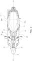
FIG. 2 is a top view of the straddled vehicle. -
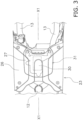
FIG. 3 is a top view of a footboard. -
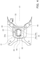
FIG. 4 is a top view of a waterproof structure in a state where a maintenance cover and the upper cover is removed from the footboard. -
FIG. 5 is a longitudinal cross-sectional view of the waterproof structure. -
FIG. 6 is a horizontal cross-sectional view of the waterproof structure. -
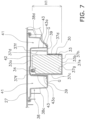
FIG. 7 is a lateral cross-sectional view of the waterproof structure. -
FIG. 8 is a top view of a waterproof structure in a state where a maintenance cover is removed from the footboard. - A straddled vehicle 1 according to an embodiment will be described below with reference to the drawings.
FIG. 1 is a side view of a straddled vehicle 1. In this embodiment, the straddled vehicle 1 is a scooter. As shown inFIG. 1 , the straddled vehicle 1 includes avehicle body frame 2, asteering device 3, afront wheel 4, aseat 5, apower unit 6, a rear wheel 7 and avehicle body cover 8. The straddled vehicle 1 further includes anelectrical component 30 and awaterproof structure 31 for waterproofing theelectrical component 30. - In the following description, the front, rear, left, and right directions corresponds to directions in which the driver views in a state where the driver is seated on the
seat 5. For example, as shown inFIG. 2 , a center axis X1 is defined on the straddled vehicle in a vehicle upper view when the straddled vehicle 1 is viewed from above. A direction, in which the center axis X1 extends in the vehicle upper view, is a front-rear direction. A direction, which is orthogonal to the center axis X1 in the vehicle upper view, is a left-right direction. The left-right direction is wording corresponding to a side direction. A direction, which is orthogonal to the front-rear direction and the left-right direction is an up-down direction. - As shown in
FIG. 1 , thevehicle body frame 2 includes ahead pipe 11, adown frame 12, a pair oflower frames 13, and aseat frame 14. Thehead pipe 11 is disposed in a center of the straddled vehicle 1 in the left-right direction. For example, thehead pipe 11 is disposed on the center axis X1 shown inFIG. 2 . Thehead pipe 11 extends forward and downward. - The down
frame 12 extends downward fromhead pipe 11. The pair oflower frames 13 extend rearward from a lower portion of thedown frame 12. The pair oflower frames 13 are disposed at an interval from each other in the left-right direction. Theseat frame 14 extends rearward and upward from a rear portion of the lower frames 13. - The
steering device 3 is rotatably supported by thehead pipe 11. Thesteering device 3 rotatably supports thefront wheel 4. Thesteering device 3 includesfront forks 15 and ahandle member 16. Thefront forks 15 are rotatably supported by thehead pipe 11. Thefront wheel 4 is rotatably supported by thefront forks 15. Thehandle member 16 is connected to thefront forks 15. - The
seat 5 is disposed behind thehead pipe 11. Theseat 5 is disposed above theseat frame 14. Theseat 5 is supported by theseat frame 14 via stays (not shown). A front portion of theseat 5 is pivotably supported by ashaft 17 extending in the left-right direction. The rear portion of theseat 5 moves in the up-down direction by pivoting theseat 5 around theshaft 17. - The
power unit 6 is disposed below theseat 5. Thepower unit 6 includes an engine.Power unit 6 can include an electric motor. The rear wheel 7 is rotatably supported by thepower unit 6. - The
vehicle body cover 8 includes afront cover 21, aleg shield 22, afootboard 23, and arear cover 24. Thefront cover 21 and theleg shield 22 are disposed at a front portion of the straddled vehicle 1. Thefront cover 21 is disposed in front of thehead pipe 11 and thedown frame 12. Theleg shield 22 is disposed behind thehead pipe 11 and thedown frame 12. - The
rear cover 24 is disposed at the rear portion of the straddled vehicle 1. Therear cover 24 is disposed below theseat 5. Therear cover 24 is disposed above thepower unit 6 and the rear wheel 7. Therear cover 24 includes aleft side cover 24a and aright side cover 24b (seeFIG. 2 ). Theleft side cover 24a and theright side cover 24b are respectively disposed at side portions of the straddled vehicle 1. - As shown in
FIG. 1 ,footboard 23 is positioned betweenleg shield 22 andrear cover 24. Thefootboard 23 extends rearward from a lower end ofleg shield 22. Thefootboard 23 is disposed in front of theseat 5 and below theseat 5. As shown inFIG. 2 , thefootboard 23 includes afootrest portion 26 and amaintenance cover 27. Thefootrest portion 26 is used as a driver's footrest. - As shown in
FIG. 3 , themaintenance cover 27 covers thewaterproof structure 31. Themaintenance cover 27 is detachably mounted to thefootrest portion 26. Themaintenance cover 27 is used as a driver's footrest in a state where themaintenance cover 27 is mounted to thefootrest portion 26. The driver can access thewaterproof structure 31 in a state where themaintenance cover 27 removed from thefootrest portion 26. - The
maintenance cover 27 may be interpreted as a member that configures thewaterproof structure 31. In this case, thewaterproof structure 31 to be described later includes themaintenance cover 27. - As shown in
FIG. 1 , theelectrical component 30 is mounted on the straddled vehicle 1. As shown inFIG. 3 , theelectrical component 30 is disposed below thefootboard 23. For example, theelectrical component 30 is disposed below themaintenance cover 27. Specifically, theelectrical component 30 is disposed below themaintenance cover 27 in a state where theelectrical component 30 is waterproofed by thewaterproof structure 31. - The
electrical component 30 includes a battery. An example, in which theelectrical component 30 is a battery, is shown in this embodiment. Theelectrical component 30 can be a electrically functional component which is different from the battery as long as theelectrical component 30 functions with electricity. Theelectrical component 30 can include both the battery and the electrically functional component. - As shown in
FIG. 4 , theelectrical component 30 includes at least oneconnection terminal 34 to which thetransmission line 32 is connected. In this embodiment, theelectrical component 30 includes abattery body 33 and twoconnection terminals 34. The twoconnection terminals 34 are provided on anupper surface 33a of thebattery body 33. - The two
connection terminals 34 are disposed on one of a left side and a right side with respect to the center axis X1. In this embodiment, the twoconnection terminals 34 are disposed on the left side. The twotransmission lines 32 are respectively connected to the twoconnection terminals 34. The twoconnection terminals 34 include aplus terminal 34a and aminus terminal 34b. - As shown in
FIG. 3 , thewaterproof structure 31 is disposed below thefootboard 23. Thewaterproof structure 31 is disposed between the pair of lower frames 13. Thewaterproof structure 31 is provided on thefootrest portion 26. - As shown in
FIG. 5 , thewaterproof structure 31 includes alower cover 35 and anupper cover 36. Thelower cover 35 is disposed below themaintenance cover 27. Thelower cover 35 is formed integrally with thefootrest portion 26. Thelower cover 35 can be formed separately from thefootrest portion 26 and can be mounted to thefootrest portion 26. Thelower cover 35 includes anelectrical component housing 37, a first surrounding wall portion 38 (an example of a first wall portion), and a connectingportion 39. As shown inFIG. 4 , thelower cover 35 further includes acover mounting portion 40. - As shown in
FIG. 5 , theelectrical component housing 37 houses theelectrical component 30. As shown inFIG. 6 , theelectrical component housing 37 covers the front, the rear, the sides, and the bottom of theelectrical component 30. Theelectrical component housing 37 includes a firstfront wall 37a, a firstrear wall 37b, a firstleft wall 37c, a firstright wall 37d, and abottom portion 37e. The firstfront wall 37a covers the front of theelectrical component 30. The firstrear wall 37b covers the rear of theelectrical component 30. The firstleft wall 37c covers the left side of theelectrical component 30. The firstright wall 37d covers the right side of theelectrical component 30. - As shown in
FIGS. 5 and7 , thebottom portion 37e covers the bottom of theelectrical component 30. Thebottom portion 37e is connected to a lower end of the firstfront wall 37a, a lower end of the firstrear wall 37b, a lower end of the firstleft wall 37c, and a lower end of the firstright wall 37d. The firstfront wall 37a, the firstrear wall 37b, the firstleft wall 37c, the firstright wall 37d, and thebottom portion 37e are integrally formed with each other. - As shown in
FIG. 6 , the firstfront wall 37a, the firstrear wall 37b, the firstleft wall 37c, and the firstright wall 37d form an outer wall of theelectrical component housing 37. Theouter walls electrical component housing 37 surround theelectrical component 30. - As shown in
FIGS. 5 and7 , thebottom portion 37e forms the bottom portion of theelectrical component housing 37. An upper end of the firstfront wall 37a, an upper end of the firstrear wall 37b, an upper end of the firstleft wall 37c, and an upper end of the firstright wall 37d form anupper opening end 37f of theelectrical component housing 37. - Preferably, as shown in
FIGS. 5 and7 , the upper openingend 37f of theelectrical component housing 37 is disposed on an upper side of a position which is defined at half of height H1 of theelectrical component 30 with respect to abottom surface 37g of theelectrical component housing 37. More preferably, the upper openingend 37f of theelectrical component housing 37 is disposed on an upper side of a position which is defined at 2/3 of the height H1 of theelectrical component 30 with respect to thebottom surface 37g of theelectrical component housing 37. - In the present embodiment, as shown in
FIG. 7 , the upper openingend 37f of theelectrical component housing 37 is disposed above theupper surface 33a of thebattery body 33. The height H1 ofelectrical component 30 is defined by a maximum height of theelectrical component 30. When theelectrical component 30 includes multiple components, the height H1 of theelectrical component 30 is defined by height of the tallest component among the multiple components. - When the height H1 of the
electrical component 30 is defined, theconnection terminals 34 are preferably excluded. For example, if theelectrical component 30 is the battery, the height H1 of theelectrical component 30 is preferably defined by alower surface 33b of thebattery body 33 and theupper surface 33a of thebattery body 33. - As shown in
FIG. 5 , the first surroundingwall portion 38 is formed integrally with thefootrest portion 26. As shown inFIG. 6 , the first surroundingwall portion 38 surrounds the front, the rear, the left side, and the right side of theelectrical component housing 37. For example, the first surroundingwall portion 38 surrounds theouter walls electrical component housing 37. The first surroundingwall portion 38 includes a secondfront wall 38a, a secondrear wall 38b, a secondleft wall 38c, and a secondright wall 38d. - The second
front wall 38a is disposed in front of theelectrical component housing 37. For example, the secondfront wall 38a is disposed at an interval from the firstfront wall 37a of theelectrical component housing 37 in front of theelectrical component housing 37. The secondrear wall 38b is disposed behind theelectrical component housing 37. For example, the secondrear wall 38b is disposed at an interval from the firstrear wall 37b of theelectrical component housing 37 behind theelectrical component housing 37. - The second
left wall 38c is disposed on the left side of theelectrical component housing 37. For example, the secondleft wall 38c is disposed at an interval from the firstleft wall 37c of theelectrical component housing 37 on the left side of theelectrical component housing 37. The secondright wall 38d is disposed on the right side of theelectrical component housing 37. For example, the secondright wall 38d is disposed at an interval from the firstright wall 37d of theelectrical component housing 37 on the right side of theelectrical component housing 37. - As shown in
FIGS. 5 and7 , the connectingportion 39 connects a lower end of the first surroundingwall portion 38 and theelectrical component housing 37. For example, the connectingportion 39 is integrally formed with the lower end of the first surroundingwall portion 38 and theouter walls electrical component housing 37. The connectingportion 39 extends from the lower end of the first surroundingwall portion 38 toward theouter walls electrical component housing 37, and is connected to theouter walls electrical component housing 37. Agroove portion 41 is formed around theelectrical component 30 by theouter walls electrical component housing 37, the first surroundingwall portion 38 and the connectingportion 39. - As shown in
FIG. 7 , the connectingportion 39 is disposed above alower surface 37h (an outer surface) of thebottom portion 37e of theelectrical component housing 37. For example, the connectingportion 39 is disposed above thebottom surface 37g of theelectrical component housing 37. Preferably, the connectingportion 39 is disposed on an upper side of a position which is defined at 1/3 of the height H1 of theelectrical component 30 with respect to thebottom surface 37g of theelectrical component housing 37. In this embodiment, the connectingportion 39 is disposed on a position which is defined at half of the height H1 of theelectrical component 30 with respect to thebottom surface 37g of theelectrical component housing 37. The arrangement position of the connectingportion 39 is defined by the upper surface of the connectingportion 39. - As shown in
FIG. 6 , the connectingportion 39 includes awiring hole 39a (an example of a hole portion) and adrain hole 39b. Thetransmission line 32 is inserted through thewiring hole 39a. Thewiring hole 39a penetrates the connectingportion 39. In other words, thewiring hole 39a penetrates thebottom portion 37e of thegroove portion 41. Thewiring hole 39a is disposed on the other of the left side and the right side with respect to the center axis X1. In this embodiment, thewiring hole 39a is disposed on the right side. - The
drain hole 39b drains water which entered thegroove portion 41. Thedrain hole 39b penetrates thebottom portion 37e of thegroove portion 41. In other words, thedrain hole 39b penetrates the connectingportion 39. In this embodiment, thedrain hole 39b is disposed on the left side with respect to the center axis X1. - As shown in
FIG. 8 , theupper cover 36 is mounted to thecover mounting portion 40. Thecover mounting portion 40 is provided between the first surroundingwall portion 38 and thefootrest portion 26. For example, thecover mounting portion 40 is provided at aportion 28 which connects an upper end of the first surroundingwall portion 38 and thefootrest portion 26. Theportion 28 which connects the upper end of the first surroundingwall portion 38 and thefootrest portion 26 can be interpreted as being included in the first surroundingwall portion 38. - As shown in
FIGS. 5 and7 , theupper cover 36 is disposed below themaintenance cover 27. For example, theupper cover 36 is disposed between themaintenance cover 27 and thelower cover 35. Theupper cover 36 includes alid portion 42 and a second surrounding wall portion 43 (an example of a second wall portion). As shown inFIG. 8 , theupper cover 36 further includes mountingarms 44. - As shown in
FIGS. 5 and7 , thelid portion 42 covers the upper openingend 37f of theelectrical component housing 37. Thelid portion 42 is disposed between themaintenance cover 27 and the upper openingend 37f of theelectrical component housing 37. Thelid portion 42 is disposed at an interval from the upper openingend 37f of theelectrical component housing 37. - The second
surrounding wall portion 43 covers the front, the rear, the left, and the right of theelectrical component housing 37. The secondsurrounding wall portion 43 is integrally formed with thelid portion 42. The secondsurrounding wall portion 43 extends from thelid portion 42 toward the connectingportion 39. A gap G is formed between atip 43a of the second surroundingwall portion 43 and the connectingportion 39. - The second
surrounding wall portion 43 overlaps theouter walls electrical component housing 37 in a vehicle front view, a vehicle rear view, and a vehicle side view of the straddled vehicle 1. For example, thetip 43a of the second surroundingwall portion 43 is disposed below the upper openingend 37f of theelectrical component housing 37. Thetip 43a of the second surroundingwall portion 43 is disposed above the connectingportion 39. - The
tip 43a of the second surroundingwall portion 43 is disposed above thebottom surface 37g of theelectrical component housing 37. Preferably, thetip 43a of the second surroundingwall portion 43 is disposed on an upper side of a position which is defined at half of the height H1 of theelectrical component 30 with respect to thebottom surface 37g of theelectrical component housing 37. - As shown in
FIGS. 5 ,6 , and7 , the second surroundingwall portion 43 is disposed between theelectrical component housing 37 and the first surroundingwall portion 38. For example, the second surroundingwall portion 43 is disposed between theouter walls electrical component housing 37 and the first surroundingwall portion 38. - Specifically, the second surrounding
wall portion 43 is disposed at an interval from theouter walls electrical component housing 37. As shown in FIG. The secondsurrounding wall portion 43 is disposed at an interval from the first surroundingwall portion 38. - More specifically, the second surrounding
wall portion 43 is disposed at an interval from theouter walls electrical component housing 37, the first surroundingwall portion 38, and the connectingportion 39, in a state where the second surroundingwall portion 43 is disposed in theabove groove portion 41. - In other words, a
labyrinth structure wall portion 43 and the groove portion 41 (theouter walls electrical component housing 37, the first surroundingwall portion 38, and the connecting portion 39). Thelabyrinth structure groove portion 41 from entering an internal space of theelectrical component housing 37. - As shown in
FIG. 8 , the mountingarm 44 is provided on thelid portion 42. For example, the mountingarm 44 is integrally formed with thelid portion 42. The mountingarm 44 can be formed separately from thelid portion 42 and can be mounted to thelid portion 42. The mountingarm 44 is detachably mounted to thecover mounting portion 40. - An air layer is formed in an internal space of the
upper cover 36 in a state where the mountingarm 44 is mounted on thecover mounting portion 40. This air layer prevents water which enters thegroove portion 41 from entering the internal space of theelectrical component housing 37. - In the straddled vehicle 1 according to this embodiment, the first surrounding
wall portion 38 of thelower cover 35 and the second surroundingwall portion 43 of theupper cover 36 are disposed at intervals from each other. The secondsurrounding wall portion 43 of theupper cover 36 and theouter walls electrical component housing 37 of thelower cover 35 are disposed at intervals from each other. The gap G is formed between thetip 43a of the second surroundingwall portion 43 and the connectingportion 39. - In other words, the
labyrinth structure wall portion 38 of thelower cover 35 and the second surroundingwall portion 43 of theupper cover 36, the space between the second surroundingwall portion 43 of theupper cover 36 and theouter walls electrical component housing 37 of thelower cover 35, and the gap G between thetip 43a of the second surroundingwall portion 43 and the connectingportion 39. - Thereby, even if water enters the space between the first surrounding
wall portion 38 of thelower cover 35 and the second surroundingwall portion 43 of theupper cover 36, the intrusion of water into the internal space of theelectrical component housing 37 is reliably prevented by thelabyrinth structure upper cover 36. Thus, thewaterproof structure 31 of the straddled vehicle 1 can suitably waterproof theelectrical component 30 of the straddled vehicle 1 in comparison with the conventional technology. - The straddled vehicle 1 is not limited to a scooter and may be another type of vehicle such as a moped.
- The
waterproof structure 31 is not limited to configuration of the above embodiment and can be modified. For example, the position of thetip 43a of the second surroundingwall portion 43 in the up-down direction and/or the position of the connectingportion 39 in the up-down direction can be changed within a range that satisfies configuration of the above embodiment. - The present invention can be used for a straddled vehicle, for example, a waterproof structure for a straddled vehicle.
-
- 1 a straddled vehicle
- 5 a seat
- 23 a footboard
- 30 an electrical component
- 31 a waterproof structure
- 32 a transmission line
- 33a an upper surface of an electrical component
- 34, 34a, 34b a connection terminal
- 35 a lower cover
- 36 an upper cover
- 37 an electrical component housing
- 37f an upper opening end of an electrical component housing
- 37g a bottom surface of an electrical component housing
- 38 a first surrounding wall portion
- 39 a connecting portion
- 39a a wiring hole
- 39b a drain hole
- 42 a lid portion
- 43 a second surrounding wall portion
- G a gap
- H1 height of an electrical component
- X1 a center axis of a straddled vehicle
Claims (9)
- A waterproof structure (31) for a straddled vehicle (1) mounting an electrical component (30) comprising:a lower cover (35) including an electrical component housing (37) covering the front, the rear, the sides and the bottom of the electrical component (30), a first wall portion (38) surrounding the front, the rear and the sides of the electrical component housing (37), and a connecting portion (39) connecting a lower end of the first wall portion (38) and the electrical component housing (37); andan upper cover (36) including a lid portion (42) covering an upper opening end (37f) of the electrical component housing (37) and a second wall portion (43) extending from the lid portion (42) toward the connecting portion (39) and covering the front, the rear and the sides of the electrical component housing (37);the second wall portion (43) is disposed at intervals from the electrical component housing (37) and the first wall portion (38) between the electrical component housing (37) and the first wall portion (38); anda gap (G) is formed between a tip (43a) of the second wall portion (43) and the connecting portion (39).
- The waterproof structure (31) for the straddled vehicle (1) according to claim 1, wherein
the tip (43a) of the second wall portion (43) is disposed on an upper side of a position which is defined at half of height (H1) of the electrical component (30) with respect to a bottom surface (37g) of the electrical component housing (37). - The waterproof structure (31) for the straddled vehicle (1) according to claim 1 or 2, wherein
the upper opening end (37f) of the electrical component housing (37) is disposed on an upper side of a position which is defined at half of height (H1) of the electrical component (30) with respect to a bottom surface (37g) of the electrical component housing (37g). - The waterproof structure (31) for the straddled vehicle (1) according to claim 3, wherein
the upper opening end (37f) of the electrical component housing (37) is disposed on an upper side of an upper surface (33a) of the electrical component (30). - The waterproof structure (31) for the straddled vehicle (1) according to any one of claims 1 to 4, whereinthe straddled vehicle (1) includes a center axis (X1) extending in a front-rear direction of the straddled vehicle (1) in a vehicle upper view;the electrical component (30) includes a connection terminal (34) to which a transmission line (32) is connected;the connecting portion (39) includes a hole portion (39a) through which the transmission line (32) passes;the hole portion (39a) is disposed on one of a left side and a right side with respect to the center axis (X1); andthe connection terminal (34) is disposed on the other of the left side and the right side.
- The waterproof structure (31) for the straddled vehicle (1) according to any one of claims 1 to 5, wherein
the connecting portion (39) of the lower cover (35) includes a drain hole (39b). - The waterproof structure (31) for the straddled vehicle (1) according to any one of claims 1 to 6, wherein
the electrical component (30) includes a battery (33). - A straddled vehicle (1) comprising:
a waterproof structure (31) according to any one of claims 1 to 7. - The straddled vehicle (1) according to claim 8, whereina seat (5);a footboard (23) disposed in front of the seat (5) and below the seat (5);the waterproof structure (31) is disposed below the footboard (23).
Applications Claiming Priority (1)
| Application Number | Priority Date | Filing Date | Title |
|---|---|---|---|
| JP2022004678A JP2023103890A (en) | 2022-01-14 | 2022-01-14 | Waterproof structure of straddle-type vehicle and straddle-type vehicle |
Publications (2)
| Publication Number | Publication Date |
|---|---|
| EP4212420A1 true EP4212420A1 (en) | 2023-07-19 |
| EP4212420B1 EP4212420B1 (en) | 2025-02-05 |
Family
ID=84462427
Family Applications (1)
| Application Number | Title | Priority Date | Filing Date |
|---|---|---|---|
| EP22212217.8A Active EP4212420B1 (en) | 2022-01-14 | 2022-12-08 | Straddled vehicle with a waterproof structure |
Country Status (4)
| Country | Link |
|---|---|
| EP (1) | EP4212420B1 (en) |
| JP (1) | JP2023103890A (en) |
| CN (1) | CN116443152A (en) |
| PH (1) | PH12022050633A1 (en) |
Citations (3)
| Publication number | Priority date | Publication date | Assignee | Title |
|---|---|---|---|---|
| JP2001114153A (en) * | 1999-10-19 | 2001-04-24 | Yamaha Motor Co Ltd | Battery cooling structure for electric motor vehicle |
| CN1071228C (en) * | 1995-11-29 | 2001-09-19 | 铃木株式会社 | scooter |
| JP5650600B2 (en) | 2011-06-30 | 2015-01-07 | 本田技研工業株式会社 | Vehicle waterproof structure |
Family Cites Families (4)
| Publication number | Priority date | Publication date | Assignee | Title |
|---|---|---|---|---|
| JP2989905B2 (en) * | 1991-01-21 | 1999-12-13 | ヤマハ発動機株式会社 | Battery box mounting structure for scooter type motorcycle |
| JP2003054469A (en) * | 2001-08-08 | 2003-02-26 | Yamaha Motor Co Ltd | Motorcycle air cleaner waterproof structure |
| JP5328441B2 (en) * | 2009-03-27 | 2013-10-30 | 本田技研工業株式会社 | Battery mounting structure for electric motorcycles |
| JP5593894B2 (en) * | 2009-07-30 | 2014-09-24 | スズキ株式会社 | A battery pack to be attached to and detached from an electric vehicle and an electric vehicle including the battery pack |
-
2022
- 2022-01-14 JP JP2022004678A patent/JP2023103890A/en active Pending
- 2022-12-08 EP EP22212217.8A patent/EP4212420B1/en active Active
- 2022-12-14 PH PH1/2022/050633A patent/PH12022050633A1/en unknown
- 2022-12-15 CN CN202211614864.3A patent/CN116443152A/en active Pending
Patent Citations (3)
| Publication number | Priority date | Publication date | Assignee | Title |
|---|---|---|---|---|
| CN1071228C (en) * | 1995-11-29 | 2001-09-19 | 铃木株式会社 | scooter |
| JP2001114153A (en) * | 1999-10-19 | 2001-04-24 | Yamaha Motor Co Ltd | Battery cooling structure for electric motor vehicle |
| JP5650600B2 (en) | 2011-06-30 | 2015-01-07 | 本田技研工業株式会社 | Vehicle waterproof structure |
Also Published As
| Publication number | Publication date |
|---|---|
| JP2023103890A (en) | 2023-07-27 |
| EP4212420B1 (en) | 2025-02-05 |
| CN116443152A (en) | 2023-07-18 |
| PH12022050633A1 (en) | 2023-07-17 |
Similar Documents
| Publication | Publication Date | Title |
|---|---|---|
| JP5605376B2 (en) | Electric motorcycle | |
| EP2468617B1 (en) | Motor driven vehicle | |
| CN117043048B (en) | Motorcycle | |
| AU2016400701A1 (en) | Electric vehicle drive device | |
| JP2000302074A (en) | Bicycle frame | |
| EP3539855B1 (en) | Support for the engine control unit of an straddled vehicle | |
| CN105073570B (en) | Electric auxiliary socket mounting structure for motor scooter | |
| JP2002225765A (en) | Storage box structure for motorcycle | |
| EP3508407A1 (en) | Saddled vehicle | |
| TWI710486B (en) | Usb terminal unit structure of saddle-ride type vehicle | |
| WO2014084195A1 (en) | Support structure for vehicle-mounted electric component | |
| EP4212420B1 (en) | Straddled vehicle with a waterproof structure | |
| JP5328441B2 (en) | Battery mounting structure for electric motorcycles | |
| EP3219594B1 (en) | Lid retaining structure | |
| JP2014184946A (en) | Battery arrangement structure of saddle riding type vehicle | |
| EP2546129A1 (en) | Two-wheeled motor vehicle | |
| EP3689724A1 (en) | Hybrid vehicle | |
| JPWO2019065474A1 (en) | Saddle type electric vehicle | |
| JP7714017B2 (en) | Saddle-type vehicle | |
| JP7450021B2 (en) | Control device drainage structure | |
| CN223479240U (en) | Frame and bicycle | |
| EP4578770A1 (en) | Straddled vehicle | |
| EP4644218A1 (en) | Electric straddled vehicle | |
| JP7670596B2 (en) | Drainage structure for saddle-type vehicles | |
| JP6990640B2 (en) | Wiring structure of side stand switch for saddle-riding vehicle |
Legal Events
| Date | Code | Title | Description |
|---|---|---|---|
| PUAI | Public reference made under article 153(3) epc to a published international application that has entered the european phase |
Free format text: ORIGINAL CODE: 0009012 |
|
| STAA | Information on the status of an ep patent application or granted ep patent |
Free format text: STATUS: REQUEST FOR EXAMINATION WAS MADE |
|
| 17P | Request for examination filed |
Effective date: 20221208 |
|
| AK | Designated contracting states |
Kind code of ref document: A1 Designated state(s): AL AT BE BG CH CY CZ DE DK EE ES FI FR GB GR HR HU IE IS IT LI LT LU LV MC ME MK MT NL NO PL PT RO RS SE SI SK SM TR |
|
| P01 | Opt-out of the competence of the unified patent court (upc) registered |
Effective date: 20230807 |
|
| STAA | Information on the status of an ep patent application or granted ep patent |
Free format text: STATUS: EXAMINATION IS IN PROGRESS |
|
| 17Q | First examination report despatched |
Effective date: 20240219 |
|
| GRAP | Despatch of communication of intention to grant a patent |
Free format text: ORIGINAL CODE: EPIDOSNIGR1 |
|
| STAA | Information on the status of an ep patent application or granted ep patent |
Free format text: STATUS: GRANT OF PATENT IS INTENDED |
|
| INTG | Intention to grant announced |
Effective date: 20240926 |
|
| GRAS | Grant fee paid |
Free format text: ORIGINAL CODE: EPIDOSNIGR3 |
|
| GRAA | (expected) grant |
Free format text: ORIGINAL CODE: 0009210 |
|
| STAA | Information on the status of an ep patent application or granted ep patent |
Free format text: STATUS: THE PATENT HAS BEEN GRANTED |
|
| AK | Designated contracting states |
Kind code of ref document: B1 Designated state(s): AL AT BE BG CH CY CZ DE DK EE ES FI FR GB GR HR HU IE IS IT LI LT LU LV MC ME MK MT NL NO PL PT RO RS SE SI SK SM TR |
|
| REG | Reference to a national code |
Ref country code: GB Ref legal event code: FG4D |
|
| REG | Reference to a national code |
Ref country code: CH Ref legal event code: EP |
|
| REG | Reference to a national code |
Ref country code: DE Ref legal event code: R096 Ref document number: 602022010325 Country of ref document: DE |
|
| REG | Reference to a national code |
Ref country code: IE Ref legal event code: FG4D |
|
| REG | Reference to a national code |
Ref country code: NL Ref legal event code: MP Effective date: 20250205 |
|
| PG25 | Lapsed in a contracting state [announced via postgrant information from national office to epo] |
Ref country code: RS Free format text: LAPSE BECAUSE OF FAILURE TO SUBMIT A TRANSLATION OF THE DESCRIPTION OR TO PAY THE FEE WITHIN THE PRESCRIBED TIME-LIMIT Effective date: 20250505 |
|
| PG25 | Lapsed in a contracting state [announced via postgrant information from national office to epo] |
Ref country code: FI Free format text: LAPSE BECAUSE OF FAILURE TO SUBMIT A TRANSLATION OF THE DESCRIPTION OR TO PAY THE FEE WITHIN THE PRESCRIBED TIME-LIMIT Effective date: 20250205 |
|
| PG25 | Lapsed in a contracting state [announced via postgrant information from national office to epo] |
Ref country code: PL Free format text: LAPSE BECAUSE OF FAILURE TO SUBMIT A TRANSLATION OF THE DESCRIPTION OR TO PAY THE FEE WITHIN THE PRESCRIBED TIME-LIMIT Effective date: 20250205 |
|
| PG25 | Lapsed in a contracting state [announced via postgrant information from national office to epo] |
Ref country code: ES Free format text: LAPSE BECAUSE OF FAILURE TO SUBMIT A TRANSLATION OF THE DESCRIPTION OR TO PAY THE FEE WITHIN THE PRESCRIBED TIME-LIMIT Effective date: 20250205 |
|
| REG | Reference to a national code |
Ref country code: LT Ref legal event code: MG9D |
|
| PG25 | Lapsed in a contracting state [announced via postgrant information from national office to epo] |
Ref country code: IS Free format text: LAPSE BECAUSE OF FAILURE TO SUBMIT A TRANSLATION OF THE DESCRIPTION OR TO PAY THE FEE WITHIN THE PRESCRIBED TIME-LIMIT Effective date: 20250605 Ref country code: NO Free format text: LAPSE BECAUSE OF FAILURE TO SUBMIT A TRANSLATION OF THE DESCRIPTION OR TO PAY THE FEE WITHIN THE PRESCRIBED TIME-LIMIT Effective date: 20250505 |
|
| PG25 | Lapsed in a contracting state [announced via postgrant information from national office to epo] |
Ref country code: NL Free format text: LAPSE BECAUSE OF FAILURE TO SUBMIT A TRANSLATION OF THE DESCRIPTION OR TO PAY THE FEE WITHIN THE PRESCRIBED TIME-LIMIT Effective date: 20250205 |
|
| PG25 | Lapsed in a contracting state [announced via postgrant information from national office to epo] |
Ref country code: HR Free format text: LAPSE BECAUSE OF FAILURE TO SUBMIT A TRANSLATION OF THE DESCRIPTION OR TO PAY THE FEE WITHIN THE PRESCRIBED TIME-LIMIT Effective date: 20250205 |
|
| PG25 | Lapsed in a contracting state [announced via postgrant information from national office to epo] |
Ref country code: LV Free format text: LAPSE BECAUSE OF FAILURE TO SUBMIT A TRANSLATION OF THE DESCRIPTION OR TO PAY THE FEE WITHIN THE PRESCRIBED TIME-LIMIT Effective date: 20250205 Ref country code: PT Free format text: LAPSE BECAUSE OF FAILURE TO SUBMIT A TRANSLATION OF THE DESCRIPTION OR TO PAY THE FEE WITHIN THE PRESCRIBED TIME-LIMIT Effective date: 20250605 |
|
| PG25 | Lapsed in a contracting state [announced via postgrant information from national office to epo] |
Ref country code: BG Free format text: LAPSE BECAUSE OF FAILURE TO SUBMIT A TRANSLATION OF THE DESCRIPTION OR TO PAY THE FEE WITHIN THE PRESCRIBED TIME-LIMIT Effective date: 20250205 Ref country code: GR Free format text: LAPSE BECAUSE OF FAILURE TO SUBMIT A TRANSLATION OF THE DESCRIPTION OR TO PAY THE FEE WITHIN THE PRESCRIBED TIME-LIMIT Effective date: 20250506 |
|
| REG | Reference to a national code |
Ref country code: AT Ref legal event code: MK05 Ref document number: 1764849 Country of ref document: AT Kind code of ref document: T Effective date: 20250205 |
|
| PG25 | Lapsed in a contracting state [announced via postgrant information from national office to epo] |
Ref country code: SE Free format text: LAPSE BECAUSE OF FAILURE TO SUBMIT A TRANSLATION OF THE DESCRIPTION OR TO PAY THE FEE WITHIN THE PRESCRIBED TIME-LIMIT Effective date: 20250205 |
|
| PG25 | Lapsed in a contracting state [announced via postgrant information from national office to epo] |
Ref country code: SM Free format text: LAPSE BECAUSE OF FAILURE TO SUBMIT A TRANSLATION OF THE DESCRIPTION OR TO PAY THE FEE WITHIN THE PRESCRIBED TIME-LIMIT Effective date: 20250205 |
|
| PG25 | Lapsed in a contracting state [announced via postgrant information from national office to epo] |
Ref country code: DK Free format text: LAPSE BECAUSE OF FAILURE TO SUBMIT A TRANSLATION OF THE DESCRIPTION OR TO PAY THE FEE WITHIN THE PRESCRIBED TIME-LIMIT Effective date: 20250205 |
|
| PG25 | Lapsed in a contracting state [announced via postgrant information from national office to epo] |
Ref country code: AT Free format text: LAPSE BECAUSE OF FAILURE TO SUBMIT A TRANSLATION OF THE DESCRIPTION OR TO PAY THE FEE WITHIN THE PRESCRIBED TIME-LIMIT Effective date: 20250205 |
|
| PG25 | Lapsed in a contracting state [announced via postgrant information from national office to epo] |
Ref country code: EE Free format text: LAPSE BECAUSE OF FAILURE TO SUBMIT A TRANSLATION OF THE DESCRIPTION OR TO PAY THE FEE WITHIN THE PRESCRIBED TIME-LIMIT Effective date: 20250205 Ref country code: CZ Free format text: LAPSE BECAUSE OF FAILURE TO SUBMIT A TRANSLATION OF THE DESCRIPTION OR TO PAY THE FEE WITHIN THE PRESCRIBED TIME-LIMIT Effective date: 20250205 |
|
| PG25 | Lapsed in a contracting state [announced via postgrant information from national office to epo] |
Ref country code: RO Free format text: LAPSE BECAUSE OF FAILURE TO SUBMIT A TRANSLATION OF THE DESCRIPTION OR TO PAY THE FEE WITHIN THE PRESCRIBED TIME-LIMIT Effective date: 20250205 |
|
| PG25 | Lapsed in a contracting state [announced via postgrant information from national office to epo] |
Ref country code: SK Free format text: LAPSE BECAUSE OF FAILURE TO SUBMIT A TRANSLATION OF THE DESCRIPTION OR TO PAY THE FEE WITHIN THE PRESCRIBED TIME-LIMIT Effective date: 20250205 |
|
| REG | Reference to a national code |
Ref country code: DE Ref legal event code: R097 Ref document number: 602022010325 Country of ref document: DE |
|
| PLBE | No opposition filed within time limit |
Free format text: ORIGINAL CODE: 0009261 |
|
| STAA | Information on the status of an ep patent application or granted ep patent |
Free format text: STATUS: NO OPPOSITION FILED WITHIN TIME LIMIT |
|
| PGFP | Annual fee paid to national office [announced via postgrant information from national office to epo] |
Ref country code: DE Payment date: 20251211 Year of fee payment: 4 |
|
| 26N | No opposition filed |
Effective date: 20251106 |
|
| PGFP | Annual fee paid to national office [announced via postgrant information from national office to epo] |
Ref country code: FR Payment date: 20251229 Year of fee payment: 4 |
|
| PGFP | Annual fee paid to national office [announced via postgrant information from national office to epo] |
Ref country code: IT Payment date: 20251231 Year of fee payment: 4 |