EP4212355B1 - Pneumatic tire - Google Patents
Pneumatic tire Download PDFInfo
- Publication number
- EP4212355B1 EP4212355B1 EP22213120.3A EP22213120A EP4212355B1 EP 4212355 B1 EP4212355 B1 EP 4212355B1 EP 22213120 A EP22213120 A EP 22213120A EP 4212355 B1 EP4212355 B1 EP 4212355B1
- Authority
- EP
- European Patent Office
- Prior art keywords
- tire
- bead
- radially outer
- apex rubber
- outer end
- Prior art date
- Legal status (The legal status is an assumption and is not a legal conclusion. Google has not performed a legal analysis and makes no representation as to the accuracy of the status listed.)
- Active
Links
Images


Classifications
-
- B—PERFORMING OPERATIONS; TRANSPORTING
- B60—VEHICLES IN GENERAL
- B60C—VEHICLE TYRES; TYRE INFLATION; TYRE CHANGING; CONNECTING VALVES TO INFLATABLE ELASTIC BODIES IN GENERAL; DEVICES OR ARRANGEMENTS RELATED TO TYRES
- B60C3/00—Tyres characterised by the transverse section
- B60C3/04—Tyres characterised by the transverse section characterised by the relative dimensions of the section, e.g. low profile
-
- B—PERFORMING OPERATIONS; TRANSPORTING
- B60—VEHICLES IN GENERAL
- B60C—VEHICLE TYRES; TYRE INFLATION; TYRE CHANGING; CONNECTING VALVES TO INFLATABLE ELASTIC BODIES IN GENERAL; DEVICES OR ARRANGEMENTS RELATED TO TYRES
- B60C15/00—Tyre beads, e.g. ply turn-up or overlap
- B60C15/06—Flipper strips, fillers, or chafing strips and reinforcing layers for the construction of the bead
- B60C15/0603—Flipper strips, fillers, or chafing strips and reinforcing layers for the construction of the bead characterised by features of the bead filler or apex
-
- B—PERFORMING OPERATIONS; TRANSPORTING
- B60—VEHICLES IN GENERAL
- B60C—VEHICLE TYRES; TYRE INFLATION; TYRE CHANGING; CONNECTING VALVES TO INFLATABLE ELASTIC BODIES IN GENERAL; DEVICES OR ARRANGEMENTS RELATED TO TYRES
- B60C15/00—Tyre beads, e.g. ply turn-up or overlap
- B60C15/02—Seating or securing beads on rims
-
- B—PERFORMING OPERATIONS; TRANSPORTING
- B60—VEHICLES IN GENERAL
- B60C—VEHICLE TYRES; TYRE INFLATION; TYRE CHANGING; CONNECTING VALVES TO INFLATABLE ELASTIC BODIES IN GENERAL; DEVICES OR ARRANGEMENTS RELATED TO TYRES
- B60C15/00—Tyre beads, e.g. ply turn-up or overlap
- B60C15/06—Flipper strips, fillers, or chafing strips and reinforcing layers for the construction of the bead
- B60C15/0603—Flipper strips, fillers, or chafing strips and reinforcing layers for the construction of the bead characterised by features of the bead filler or apex
- B60C15/0607—Flipper strips, fillers, or chafing strips and reinforcing layers for the construction of the bead characterised by features of the bead filler or apex comprising several parts, e.g. made of different rubbers
-
- B—PERFORMING OPERATIONS; TRANSPORTING
- B60—VEHICLES IN GENERAL
- B60C—VEHICLE TYRES; TYRE INFLATION; TYRE CHANGING; CONNECTING VALVES TO INFLATABLE ELASTIC BODIES IN GENERAL; DEVICES OR ARRANGEMENTS RELATED TO TYRES
- B60C15/00—Tyre beads, e.g. ply turn-up or overlap
- B60C15/06—Flipper strips, fillers, or chafing strips and reinforcing layers for the construction of the bead
- B60C15/0603—Flipper strips, fillers, or chafing strips and reinforcing layers for the construction of the bead characterised by features of the bead filler or apex
- B60C2015/061—Dimensions of the bead filler in terms of numerical values or ratio in proportion to section height
-
- Y—GENERAL TAGGING OF NEW TECHNOLOGICAL DEVELOPMENTS; GENERAL TAGGING OF CROSS-SECTIONAL TECHNOLOGIES SPANNING OVER SEVERAL SECTIONS OF THE IPC; TECHNICAL SUBJECTS COVERED BY FORMER USPC CROSS-REFERENCE ART COLLECTIONS [XRACs] AND DIGESTS
- Y02—TECHNOLOGIES OR APPLICATIONS FOR MITIGATION OR ADAPTATION AGAINST CLIMATE CHANGE
- Y02T—CLIMATE CHANGE MITIGATION TECHNOLOGIES RELATED TO TRANSPORTATION
- Y02T10/00—Road transport of goods or passengers
- Y02T10/80—Technologies aiming to reduce greenhouse gasses emissions common to all road transportation technologies
- Y02T10/86—Optimisation of rolling resistance, e.g. weight reduction
Definitions
- the present invention relates to an assembly of a wheel rim and a pneumatic tire.
- WO 2020/122240 A1 discloses a pneumatic tire for a small shuttle bus with a gross vehicle weight exceeding 3 tons. This type of pneumatic tire has a small diameter in order to secure a wide riding space.
- the pneumatic tire of WO 2020/122240 A1 has increased load bearing capacity by specifying the arrangement of the circumferential grooves, the ratio of the outer diameter of the tire to the wheel rim diameter, and the like.
- the pneumatic tire of WO 2020/122240 A1 Since the pneumatic tire of WO 2020/122240 A1 has a small diameter, the air volume for supporting the weight of the vehicle is reduced, and the tire cross-sectional height is small. For this reason, the pneumatic tire has a problem that strain is concentrated on the bead portions during running with heavy loads, and damage starting from the bead portion is likely to occur.
- the present invention was made in view of the situation as described above, and a primary objective of the present invention is to improve the durability of the bead portions of a pneumatic tire mounted on a wheel rim whose rim diameter is 12 to 17 inches.
- a pneumatic tire configured to be mounted on a wheel rim whose rim diameter is in a range from 12 to 17 inches
- the assembly according to the present invention can improve the durability of the bead portion by adopting the above configuration.
- the tire 1 is used in a new small shuttle bus which focuses on transporting people and goods within cities. Buses of this type are required to have a large boarding space, and some of them have a gross vehicle weight exceeding 3 tons.
- Such bus may be an electric vehicle equipped with an in-wheel motor (not shown) and equipped with an automatic driving function.
- the present invention however, may be applied to tires for passenger cars, heavy duty vehicles and the like.
- FIG 1 shows the tire 1 mounted on a wheel rim R and inflated to a specified internal pressure.
- the specified internal pressure refers to the internal pressure at which the tire 1 exhibits the best performance, for example, 400 to 1100 kPa, or 500 to 900 kPa.
- the wheel rim R As for the wheel rim R, one that fits the tire 1 is adopted.
- the wheel rim R is a wheel rim specified for the tire by a standard included in a standardization system on which the tire is based, for example, the "normal wheel rim” in JATMA, "Design Rim” in TRA, and “Measuring Rim” in ETRTO.
- the tire 1 is mounted on a wheel rim R whose rim diameter RD in a range from 12 to 17 inches.
- the tire 1 of the present invention has a small diameter for the vehicle size.
- the tire 1 has a ratio (SH/SW) of the tire cross-sectional height SH to the tire cross-sectional width SW which is in a range from 0.30 to 0.45, and a ratio (RW/SW) of the rim width RW of the wheel rim R to the tire cross-sectional width SW which is in a range from 0.78 to 0.99.
- the tire 1 of the present invention can secure a low aspect ratio and an air volume for supporting the weight of the vehicle.
- a size of 205/40R15 or 215/45R12 is suitable.
- the rim width of a wheel rim R suitable for the tire 1 of these sizes is 7.0J or 7.5J.
- the rim diameter RD is the outer diameter of the main portion (or bead seat) Rh (flange Rf is not included) of the wheel rim R.
- the cross-sectional width SW of the tire is the maximum axial width of the tire 1 excluding axially protruding rim protectors (not shown).
- the cross-sectional height SH of the tire is the radial distance between the radially outermost end of the tread portion 2 of the tire 1, and a radial position corresponding to the wheel rim diameter RD.
- a line extending parallel to the tire axial direction through the above-said radial position is known as the bead base line.
- the wheel rim width RW is the axial distance between the radially inner ends of the flanges Rf on both sides in the tire axial direction.
- the rim diameter RD and rim width RW may be determined on the basis of the JATMA standard on which the wheel rim R is based.
- the tire 1 comprises a pair of bead portions 4 each with a bead core 5 embedded therein.
- One of or each of the bead portions 4 is provided with a bead apex rubber 8 extending radially outwardly from the radially outer surface 5a of the bead core 5.
- the bead apex rubber 8 is disposed in each of the bead portions 4. Structurally, strain tends to concentrate on the radially outer end 8e of the bead apex rubber 8.
- FIG 2 is an enlarged view of the bead portion 4 shown in FIG 1 .
- a first region 10 is defined in the bead portion 4 as shown in FIG 2 .
- the first region 10 is defined between a first tire radial direction line n1 and a second tire radial direction line n2.
- the first tire radial direction line n1 is a straight line extending in the tire radial direction through the radially outer end 11e of the contact area 11 where the bead portion 4 comes into contact with the flange Rf of the wheel rim R.
- the second tire radial direction line n2 is a straight line extending in the tire radial direction through an axial position 12 spaced 10 mm axially outward from the radially outer end 11e of the contact area 11.
- the first region 10 is a region where large strain concentrates during running with heavy loads.
- the ratio (So/S) of the cross-sectional area So of the radially outer portion 8A to the cross-sectional area S of the bead apex rubber 8 is preferably 0.2 or more. Since the ratio (So/S) is 0.2 or more, the rigidity of the portion axially outside the bead core 5 is maintained, thereby distortion due to running is suppressed, and durability is improved.
- the ratio (So/S) is more preferably 0.25 or more.
- the ratio (So/S) is preferably 0.35 or less, more preferably 0.30 or less.
- the radially outer ends 8e of the bead apex rubbers 8 are respectively positioned axially inside the axial edges 7h of the radially inner belt ply 7a. And the radially outer ends 8e of the bead apex rubbers 8 are respectively positioned axially outside the axial edges 7k of the radially outer belt ply 7b in the present embodiment.
- the outside apex rubber 9 is disposed axially outside the turned-up portion 6b.
- the outside apex rubber 9 is disposed adjacently to the axially outer side of the turned-up portion 6b of the inner carcass ply 6A.
- the outside apex rubber 9 has a complex elastic modulus E* which is the same as that of the bead apex rubber 8.
- E* complex elastic modulus
- FIG 3 is an enlarged view of the bead portion 4.
- the outside apex rubber 9 is formed in a sheet shape with a thickness "d" of 40% or less of the maximum axial width Wa of the bead apex rubber 8.
- Such outside apex rubber 9 maintains the width of the bead portion 4 small to ensure deformation (deflection) during running, and disperses the load to enhance the durability.
- the radially inner end 9i of the outside apex rubber 9 is located radially outside the radially outer end 5j of the bead core 5.
- the radially outer end 9e of the outside apex rubber 9 is disposed at a position axially outwardly spaced apart from the first region 10 by 10 mm or more. As a result, the rigidity of the bead portion 4 is enhanced, and the durability is further improved.
- the axial distance Lb between the radially outer end 9e of the outside apex rubber 9 and the first region 10 (the position 12 shown in FIG 2 ) is preferably not less than 160%, more preferably not less than 180%, but preferably not more than 240%, more preferably not more than 220% of the maximum width Wa of the bead apex rubber 8.
- the distance L1 in the tire radial direction between the radially outer end 9e of the outside apex rubber 9 and the radially outer end 8e of the bead apex rubber 8 is preferably not less than 50%, more preferably not less than 55%, but preferably not more than 70%, more preferably not more than 65% of the radial height HB of the outside apex rubber 9.
- the radial height HB of the outside apex rubber 9 is preferably not less than 200%, more preferably not less than 220%, but preferably not more than 280%, more preferably not more than 260% of the radial height HA (shown in FIG 1 ) of the bead apex rubber 8.
- the sidewall rubber 3G and the clinch rubber 4G may be made of various well-known materials.
- the clinch rubber 4G is, for example, disposed adjacently to the radially inner side of the sidewall rubber 3G
- the clinch rubber 4G comprises a portion coming into contact with the wheel rim.
- the radially inner end 4i of the clinch rubber 4G is positioned radially inside the radially inner end 5i of the bead core 5 as shown in FIG 3 .
- the chafer 13 is formed in a U shape composed of a first portion 13a, a second portion 13b and a third portion 13c.
- the third portion 13c is positioned radially inside the radially inner end 5i of the bead core 5, and extends along the bead base so as to be able to contact with the bead seat of the wheel rim R.
- the first portion 13a extends radially outwardly from the axially inner end of the third portion 13c, facing the inner cavity of the tire 1.
- the second portion 13b extends radially outwardly from the axially outer end of the third portion 13c.
- the second portion 13b extends between the turned-up portion 6b of the inner carcass ply 6A and the outside apex rubber 9,
Landscapes
- Engineering & Computer Science (AREA)
- Mechanical Engineering (AREA)
- Tires In General (AREA)
Description
- The present invention relates to an assembly of a wheel rim and a pneumatic tire.
-
WO 2020/122240 A1 discloses a pneumatic tire for a small shuttle bus with a gross vehicle weight exceeding 3 tons. This type of pneumatic tire has a small diameter in order to secure a wide riding space. In addition, the pneumatic tire ofWO 2020/122240 A1 has increased load bearing capacity by specifying the arrangement of the circumferential grooves, the ratio of the outer diameter of the tire to the wheel rim diameter, and the like. -
US 2018/0111425 A1 discloses an assembly according to the preamble of claim 1. Other related tires or assemblies are known fromUS 5,885,385 A ,JP 2017- 136967 A JP 2021-059194 A WO 2015/097926 A1 ,US 2020/0023690 A1 ,JP 2018-154164 A US 2021/0300128 A1 . - Since the pneumatic tire of
WO 2020/122240 A1 has a small diameter, the air volume for supporting the weight of the vehicle is reduced, and the tire cross-sectional height is small. For this reason, the pneumatic tire has a problem that strain is concentrated on the bead portions during running with heavy loads, and damage starting from the bead portion is likely to occur. - The present invention was made in view of the situation as described above, and a primary objective of the present invention is to improve the durability of the bead portions of a pneumatic tire mounted on a wheel rim whose rim diameter is 12 to 17 inches.
- According to the present invention, a pneumatic tire configured to be mounted on a wheel rim whose rim diameter is in a range from 12 to 17 inches,
- has a ratio (SH/SW) of the cross-sectional height SH of the tire to the cross-sectional width SW of the tire which is in a range from 0.30 to 0.45, and
- a ratio (RW/SW) between the width RW of the wheel rim and the cross-sectional width SW of the tire which is in a range from 0.78 to 0.99, and
- comprises a pair of bead portions each with a bead core embedded therein, a bead apex rubber disposed in one of or each of the bead portions and extending radially outwardly from a radially outer surface of the bead core so as to have a radially outer end not positioned within a first region, a carcass ply extending between the bead portions and turned up around the bead core in each bead portion from the axially inside to the outside so as to form a pair of turned-up portions extending radially outward and a main portion therebetween, and an outside apex rubber disposed axially outward of each of the turned-up portions, wherein
- the first region is defined between a first tire radial direction line and a second tire radial direction line, when the tire is mounted on a wheel rim, inflated to a specified internal pressure and loaded with no tire load, the specified internal pressure being an air pressure specified for the tire by a standard included in a standardization system on which the tire is based,
- the first tire radial direction line is a straight line extending in the tire radial direction through a radially outer end of a contact area where the bead portion comes into contact with a flange of the wheel rim, and
- the second tire radial direction line is a straight line extending in the tire radial direction through a position spaced 10 mm axially outward from the radially outer end of the contact area. The outside apex rubber is sheet-shaped and has a thickness of not more than 40 % of a maximum axial width of the bead apex rubber. The axial distance La between the radially outer end of the bead apex rubber and the radially outer end of the contact area is not more than 2 mm.
- The assembly according to the present invention can improve the durability of the bead portion by adopting the above configuration.
-
-
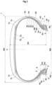
FIG 1 is a tire meridian sectional view of an assembly as an embodiment of the present invention. -
FIG 2 andFIG 3 are enlarged views of one of the bead portions shown inFIG 1 which are the same view but differently provided with reference numbers. - An embodiment of the present invention will now be described in detail in conjunction with accompanying drawings.
-
FIG 1 is a tire meridian sectional view including a tire rotation axis (not shown) of a pneumatic tire 1 as an embodiment of the present invention. - In the present embodiment, the tire 1 is used in a new small shuttle bus which focuses on transporting people and goods within cities. Buses of this type are required to have a large boarding space, and some of them have a gross vehicle weight exceeding 3 tons. Such bus may be an electric vehicle equipped with an in-wheel motor (not shown) and equipped with an automatic driving function. The present invention however, may be applied to tires for passenger cars, heavy duty vehicles and the like.
-
FIG 1 shows the tire 1 mounted on a wheel rim R and inflated to a specified internal pressure. The specified internal pressure refers to the internal pressure at which the tire 1 exhibits the best performance, for example, 400 to 1100 kPa, or 500 to 900 kPa. - When the tire 1 is for passenger cars or heavy duty vehicles, the prescribed internal pressure is air pressure specified for the tire by a standard included in a standardization system on which the tire is based, for example, the "maximum air pressure" in JATMA, maximum value listed in the "TIRE LOAD LIMITS AT VARIOUS COLD INFLATION PRESSURES" table in TRA, and "INFLATION PRESSURE" in ETRTO.
- In this application including specification and claims, various dimensions, positions and the like of the tire refer to those under the standard state unless otherwise noted, wherein the standard state is such a state that the tire is inflated to the prescribed internal pressure, and loaded with no tire load.
- As for the wheel rim R, one that fits the tire 1 is adopted. When the tire 1 is for passenger cars or heavy duty vehicles, the wheel rim R is a wheel rim specified for the tire by a standard included in a standardization system on which the tire is based, for example, the "normal wheel rim" in JATMA, "Design Rim" in TRA, and "Measuring Rim" in ETRTO.
- The tire 1 is mounted on a wheel rim R whose rim diameter RD in a range from 12 to 17 inches. Thus, the tire 1 of the present invention has a small diameter for the vehicle size.
- The tire 1 has a ratio (SH/SW) of the tire cross-sectional height SH to the tire cross-sectional width SW which is in a range from 0.30 to 0.45, and
a ratio (RW/SW) of the rim width RW of the wheel rim R to the tire cross-sectional width SW which is in a range from 0.78 to 0.99. - Thereby, the tire 1 of the present invention can secure a low aspect ratio and an air volume for supporting the weight of the vehicle.
- As such tire 1, for example, a size of 205/40R15 or 215/45R12 is suitable.
- On the other hand, the rim width of a wheel rim R suitable for the tire 1 of these sizes is 7.0J or 7.5J.
- In addition, in the tire 1 of the present invention, it is preferable that the wheel rim R has a large space for accommodating an in-wheel motor
- The rim diameter RD is the outer diameter of the main portion (or bead seat) Rh (flange Rf is not included) of the wheel rim R.
- The cross-sectional width SW of the tire is the maximum axial width of the tire 1 excluding axially protruding rim protectors (not shown).
- The cross-sectional height SH of the tire is the radial distance between the radially outermost end of the tread portion 2 of the tire 1, and a radial position corresponding to the wheel rim diameter RD. A line extending parallel to the tire axial direction through the above-said radial position is known as the bead base line. The wheel rim width RW is the axial distance between the radially inner ends of the flanges Rf on both sides in the tire axial direction. When the tire 1 is for passenger cars or heavy duty vehicles, the rim diameter RD and rim width RW may be determined on the basis of the JATMA standard on which the wheel rim R is based.
- The tire 1 comprises a pair of
bead portions 4 each with abead core 5 embedded therein. One of or each of thebead portions 4 is provided with abead apex rubber 8 extending radially outwardly from the radiallyouter surface 5a of thebead core 5. In the present embodiment, thebead apex rubber 8 is disposed in each of thebead portions 4. Structurally, strain tends to concentrate on the radiallyouter end 8e of thebead apex rubber 8. -
FIG 2 is an enlarged view of thebead portion 4 shown inFIG 1 . - In the present invention, a
first region 10 is defined in thebead portion 4 as shown inFIG 2 . Thefirst region 10 is defined between a first tire radial direction line n1 and a second tire radial direction line n2. - The first tire radial direction line n1 is a straight line extending in the tire radial direction through the radially
outer end 11e of thecontact area 11 where thebead portion 4 comes into contact with the flange Rf of the wheel rim R. - The second tire radial direction line n2 is a straight line extending in the tire radial direction through an
axial position 12 spaced 10 mm axially outward from the radiallyouter end 11e of thecontact area 11. - The
first region 10 is a region where large strain concentrates during running with heavy loads. - In the present embodiment, the radially
outer end 11e of thecontact area 11 is positioned radially inside the radiallyouter end 5j of thebead core 5. - According to the present invention, the radially
outer end 8e of thebead apex rubber 8 is not located within thefirst region 10. Therefore, damage starting from the radiallyouter end 8e is suppressed, and the durability of thebead portion 4 is improved. - As shown in
FIG 1 , the tire 1 comprises acarcass 6 extending between thebead cores 5 in the present embodiment. - Further, the tire 1 comprises a
tread reinforcing belt 7, anoutside apex rubber 9, asidewall rubber 3G, aclinch rubber 4G, and achafer 13. - The
carcass 6 comprises at least one carcass ply (6A, 6B) made of rubberized carcass cords (not shown) and extending between thebead portions 4 through the tread portion 2 and the sidewall portions 3, and turned-up around thebead core 5 in each of thebead portions 4 from the inside to the outside in the tire axial direction so as to form a pair of turned-upportions 6b and amain portion 6a therebetween. - In the present embodiment, the
carcass 6 is composed of two carcass plies 6A and 6B arranged inside and outside in the tire radial direction in the tread portion 2 although thecarcass 6 may be composed of a single carcass ply (6A, 6B). - Each of the turned-up
portions 6b extends radially outwardly, and the radiallyouter end 6e thereof is positioned radially outside the radiallyouter end 8e of thebead apex rubber 8 in the present embodiment. - In the present embodiment, the
tread reinforcing belt 7 is disposed in the tread portion 2 and composed of a radiallyinner belt ply 7a and a radiallyouter belt ply 7b. Theaxial edges 7h of the radiallyinner belt ply 7a are respectively positioned axially outside theaxial edges 7k of the radiallyouter belt ply 7b. - Each of the belt plies 7a and 7b is made of rubberized parallel belt cords (not shown), for example, steel cords. As to the structure of the belt, those for general truck/bus tires may be adopted.
- As shown in
FIG 2 , thebead apex rubber 8 is disposed between themain portion 6a and each of the turned-upportion 6b of the radiallyouter carcass ply 6B so that thebead apex rubber 8 is in contact with the axially outer side of themain portion 6a and the axially inner side of the turned-upportion 6b. - In the present embodiment, the radially
outer end 8e of thebead apex rubber 8 is located axially inside than thefirst region 10. That is, thebead apex rubber 8 does not exist in thefirst region 10. Accordingly, the interface between thebead apex rubber 8 and the carcass ply is not formed in thefirst region 10, so damage due to carcass play separation does not occur, and the durability of thebead portion 4 is further improved. If the radiallyouter end 8e of thebead apex rubber 8 is positioned axially outside thefirst region 10, the interface is formed, but damage originating from the radiallyouter end 8e is suppressed, therefore, the durability of thebead portion 4 may be improved. - It is preferable that the axial distance La between the radially
outer end 8e of thebead apex rubber 8 and the radiallyouter end 11e of thecontact area 11 is 2 mm or less. If the radiallyouter end 8e of thebead apex rubber 8 is disposed at a position more than 2 mm axially inward of the radiallyouter end 11e of thecontact area 11, it becomes difficult to increase the rigidity around the radiallyouter end 11e where a particularly large strain occurs, and thereby the durability may not be improved. - It is preferable that the
bead apex rubber 8 has complex elastic modulus E* of 25 MPa or more, more preferably 30 MPa or more, but 40 MPa or less, more preferably 35 MPa or less. - The complex elastic modulus E* was measured under the following conditions according to the Japanese Industrial Standard (JIS) K6394 by using a spectrometer manufactured by Ueshima Seisakusho Co., Ltd.
- temperature: 70 degrees C.
- amplitude of dynamic strain: 1%
- frequency: 10Hz
- The
bead apex rubber 8 has its radiallyouter portion 8A positioned axially outside the axiallyouter end 5e of thebead core 5 as shown inFIG 2 . - In the tire meridian cross section, the ratio (So/S) of the cross-sectional area So of the radially
outer portion 8A to the cross-sectional area S of thebead apex rubber 8 is preferably 0.2 or more. Since the ratio (So/S) is 0.2 or more, the rigidity of the portion axially outside thebead core 5 is maintained, thereby distortion due to running is suppressed, and durability is improved. - In order to enhance such action, the ratio (So/S) is more preferably 0.25 or more.
- If the ratio (So/S) is excessively large, a large load due to running may be applied to the radially inner portion of the
bead apex rubber 8, and as result, the durability may be deteriorated. Therefore, the ratio (So/S) is preferably 0.35 or less, more preferably 0.30 or less. - As shown in
FIG 1 , the radial height HA of thebead apex rubber 8 is preferably not less than 175%, more preferably not less than 200%, but preferably not more than 275%, more preferably not more than 250% of the radial height HC of thebead core 5. As a result, the above effects are effectively exhibited. - The radially outer ends 8e of the
bead apex rubbers 8 are respectively positioned axially inside theaxial edges 7h of the radiallyinner belt ply 7a. And the radially outer ends 8e of thebead apex rubbers 8 are respectively positioned axially outside theaxial edges 7k of the radiallyouter belt ply 7b in the present embodiment. - The
outside apex rubber 9 is disposed axially outside the turned-upportion 6b. In the present embodiment, theoutside apex rubber 9 is disposed adjacently to the axially outer side of the turned-upportion 6b of theinner carcass ply 6A. - In the present embodiment, the
outside apex rubber 9 has a complex elastic modulus E* which is the same as that of thebead apex rubber 8. As a result, the difference in the amount of strain between thebead apex rubber 8 and theoutside apex rubber 9 is reduced, so strain is less likely to occur in the entire bead portion, and the effect of improving durability is exhibited. -
FIG 3 is an enlarged view of thebead portion 4. As shown inFIG 3 , theoutside apex rubber 9 is formed in a sheet shape with a thickness "d" of 40% or less of the maximum axial width Wa of thebead apex rubber 8. - Such
outside apex rubber 9 maintains the width of thebead portion 4 small to ensure deformation (deflection) during running, and disperses the load to enhance the durability. - The radially
inner end 9i of theoutside apex rubber 9 is positioned radially inside a radial position P1 which is 2 mm radially outward from the radiallyouter end 5j of thebead core 5. As a result, the rigidity step difference in the vicinity of thebead core 5 is reduced, and the durability of thebead portion 4 is further improved. - In the present embodiment, the radially
inner end 9i of theoutside apex rubber 9 is located radially outside the radiallyouter end 5j of thebead core 5. - In addition, the radially
inner end 9i of theoutside apex rubber 9 is located radially outside the radiallyouter end 11e of thecontact area 11. - The radially
outer end 9e of theoutside apex rubber 9 is disposed at a position axially outwardly spaced apart from thefirst region 10 by 10 mm or more. As a result, the rigidity of thebead portion 4 is enhanced, and the durability is further improved. The axial distance Lb between the radiallyouter end 9e of theoutside apex rubber 9 and the first region 10 (theposition 12 shown inFIG 2 ) is preferably not less than 160%, more preferably not less than 180%, but preferably not more than 240%, more preferably not more than 220% of the maximum width Wa of thebead apex rubber 8. - In the present embodiment, the radially
outer end 9e of theoutside apex rubber 9 is located radially outside the radiallyouter end 4e of theclinch rubber 4G - The distance L1 in the tire radial direction between the radially
outer end 9e of theoutside apex rubber 9 and the radiallyouter end 8e of thebead apex rubber 8 is preferably not less than 50%, more preferably not less than 55%, but preferably not more than 70%, more preferably not more than 65% of the radial height HB of theoutside apex rubber 9. - The radial height HB of the
outside apex rubber 9 is preferably not less than 200%, more preferably not less than 220%, but preferably not more than 280%, more preferably not more than 260% of the radial height HA (shown inFIG 1 ) of thebead apex rubber 8. - As a result, the above effects are effectively exhibited.
- In the present embodiment, the
sidewall rubber 3G and theclinch rubber 4G may be made of various well-known materials. - The
clinch rubber 4G is, for example, disposed adjacently to the radially inner side of thesidewall rubber 3G - The
clinch rubber 4G comprises a portion coming into contact with the wheel rim. - The radially
inner end 4i of theclinch rubber 4G is positioned radially inside the radiallyinner end 5i of thebead core 5 as shown inFIG 3 . - In the present embodiment, the
chafer 13 is formed in a U shape composed of afirst portion 13a, asecond portion 13b and athird portion 13c. - The
third portion 13c is positioned radially inside the radiallyinner end 5i of thebead core 5, and extends along the bead base so as to be able to contact with the bead seat of the wheel rim R. - The
first portion 13a extends radially outwardly from the axially inner end of thethird portion 13c, facing the inner cavity of the tire 1. - The
second portion 13b extends radially outwardly from the axially outer end of thethird portion 13c. In the present embodiment, thesecond portion 13b extends between the turned-upportion 6b of theinner carcass ply 6A and theoutside apex rubber 9, - While detailed description has been made of a preferable embodiment of the present invention, the present invention can be embodied in various forms without being limited to the illustrated embodiment.
- Based on the structure shown in
FIG 1 , pneumatic tires were experimentally manufactured as test tires (Comparative Example and Examples 1-7 according to the present invention), and tested for the bead durability. - Specifications of the test tires are shown in Table 1.
- Common specifications to all the test tires and the test method are as follows.
- Using test vehicles, the test tires were run under the following conditions to measure the running distance until damage was occurred in the bead portions.
- Tire size: 205/40R15
- Rim size: 7.0J
- Tire inflation pressure: 520 kPa
- SH/SW: 0.40
- RW/SW: 0.87
- Test vehicle: E-Pallet manufactured by Toyota Motor Corporation
- The results are indicated in Table 1 by an index based on Example 1 being 100, wherein values of 95 or higher are acceptable.
- In Table 1, the minus sign "-" of La means that the radially
outer end 8e of thebead apex rubber 8 was positioned axially outside the radiallyouter end 11e of thecontact area 11. In Table 1, "*1" means that the radiallyinner end 9i of theoutside apex rubber 9 was positioned 5 mm radially outward from the radiallyouter end 5j of thebead core 5. In Table 1, "*2" means that the radiallyouter end 9e of theoutside apex rubber 9 was positioned 5 mm axially outward from the radiallyouter end 11e of thecontact area 11.Table 1 Tire Comparative example Example 1 Example 2 Example 3 Example 4 Example 5 Example 6 Example 7 La (mm) -5.0 2.0 2.0 2.0 2.0 2.0 2.0 -15.0 Ratio (Sa/S) 0.25 0.25 0.1 0.25 0.25 0.25 0.25 0.25 Outside apex rubber Absence Absence Absence Presence Presence Presence Presence Presence Second apex rubber inner end position -- -- -- @P1 *1 @P1 @P1 @P1 Lb (mm) -- -- -- 10 10 5 *2 10 Durability 90 100 95 110 105 105 100 108 - From the test results, it was confirmed that Example tires according to the present invention were improved in bead durability as compared to Comparative example tire.
-
- 1 pneumatic tire
- 4 bead portion
- 5 bead core
- 5a radially outer surface
- 8 bead apex rubber
- 8e radially outer end
- R wheel rim
- Rf rim flange
- 10 first region
- 11 contact area
- 11e radially outer end
- n1 first tire radial direction line
- n2 second tire radial direction line
Claims (5)
- An assembly of a wheel rim (R) whose rim diameter (RD) is in a range from 12 to 17 inches and a pneumatic tire (1) mounted on the wheel rim, wherein a ratio (SH/SW) of the cross-sectional height SH of the tire (1) to the cross-sectional width SW of the tire (1) is in a range from 0.30 to 0.45, and a ratio (RW/SW) between the width RW of the wheel rim (R) and the cross-sectional width SW of the tire (1) is in a range from 0.78 to 0.99,the pneumatic tire (1) comprising a pair of bead portions (4) each with a bead core (5) embedded therein, a bead apex rubber (8) disposed in one of or alternatively each of the bead portions (4) and extending radially outwardly from a radially outer surface (5a) of the bead core (5) so as to have a radially outer end (8e) not positioned within a first region (10), a carcass ply (6A, 6B) extending between the bead portions (4) and turned up around the bead core (5) in each bead portion (4) from the axially inside to the outside so as to form a pair of turned-up portions (6b) extending radially outward and a main portion (6a) therebetween, and an outside apex rubber (9) disposed axially outward of each of the turned-up portions (6b),wherein the first region (10) is defined between a first tire radial direction line (n1) and a second tire radial direction line (n2), when the tire (1) is mounted on a wheel rim (R), inflated to a specified internal pressure and loaded with no tire load, the specified internal pressure being an air pressure specified for the tire (1) by a standard included in a standardization system on which the tire (1) is based,the first tire radial direction line (n1) is a straight line extending in the tire radial direction through a radially outer end (11e) of a contact area (11) where the bead portion (4) comes into contact with a flange (Rf) of the wheel rim (R), andthe second tire radial direction line (n2) is a straight line extending in the tire radial direction through a position spaced 10 mm axially outward from the radially outer end (11e) of the contact area (11),characterized in that the outside apex rubber (9) is sheet-shaped and has a thickness (d) of not more than 40 % of a maximum axial width (Wa) of the bead apex rubber (8) and the axial distance La between the radially outer end (8e) of the bead apex rubber (8) and the radially outer end (11e) of the contact area (11) is not more than 2 mm.
- The assembly according to claim 1, wherein
the radially outer end (8e) of the bead apex rubber (8) is positioned axially inside than the first region (10). - The assembly according to claim 1 or 2, whereinthe bead apex rubber (8) has its radially outer portion (8A) positioned axially outside the axially outer end (5e) of the bead core (5), andin a meridian cross section of the tire (1), the cross-sectional area of the radially outer portion (8A) is not less than 0.2 times the cross-sectional area of the bead apex rubber (8).
- The assembly according to any one of the preceding claims, wherein
the radially inner end (9i) of the outside apex rubber (9) is positioned radially inward than a radial position (P1) 2 mm radially outward from the radially outer end (5j) of the bead core (5). - The assembly according to any one of the preceding claims, wherein
the radially outer end (9e) of the outside apex rubber (9) is disposed at an axial position (12) at least 10 mm axially outward from the first region (10).
Applications Claiming Priority (1)
| Application Number | Priority Date | Filing Date | Title |
|---|---|---|---|
| JP2022003234A JP7806504B2 (en) | 2022-01-12 | 2022-01-12 | pneumatic tires |
Publications (2)
| Publication Number | Publication Date |
|---|---|
| EP4212355A1 EP4212355A1 (en) | 2023-07-19 |
| EP4212355B1 true EP4212355B1 (en) | 2025-07-02 |
Family
ID=84519404
Family Applications (1)
| Application Number | Title | Priority Date | Filing Date |
|---|---|---|---|
| EP22213120.3A Active EP4212355B1 (en) | 2022-01-12 | 2022-12-13 | Pneumatic tire |
Country Status (3)
| Country | Link |
|---|---|
| US (1) | US20230219377A1 (en) |
| EP (1) | EP4212355B1 (en) |
| JP (1) | JP7806504B2 (en) |
Families Citing this family (4)
| Publication number | Priority date | Publication date | Assignee | Title |
|---|---|---|---|---|
| JP2025084553A (en) | 2023-11-22 | 2025-06-03 | 住友ゴム工業株式会社 | Pneumatic tires |
| JP2025095936A (en) | 2023-12-15 | 2025-06-26 | 住友ゴム工業株式会社 | Pneumatic tires |
| JP2025107905A (en) | 2024-01-09 | 2025-07-22 | 住友ゴム工業株式会社 | Pneumatic tires |
| JP2025112978A (en) | 2024-01-22 | 2025-08-01 | 住友ゴム工業株式会社 | pneumatic tires |
Citations (2)
| Publication number | Priority date | Publication date | Assignee | Title |
|---|---|---|---|---|
| US5885385A (en) * | 1995-05-23 | 1999-03-23 | The Yokohama Rubber Co., Ltd. | Pneumatic tire with sidewall reinforcing rubber layer |
| JP2018154164A (en) * | 2017-03-16 | 2018-10-04 | 住友ゴム工業株式会社 | Pneumatic tire |
Family Cites Families (12)
| Publication number | Priority date | Publication date | Assignee | Title |
|---|---|---|---|---|
| JPH0958224A (en) * | 1995-06-13 | 1997-03-04 | Sumitomo Rubber Ind Ltd | Pneumatic tire |
| JP4464700B2 (en) * | 2004-01-28 | 2010-05-19 | 住友ゴム工業株式会社 | Pneumatic tire and manufacturing method thereof |
| CN106166922B (en) * | 2011-08-26 | 2018-04-24 | 株式会社普利司通 | Pneumatic radial tire for car and its application method |
| JP5947783B2 (en) * | 2013-12-24 | 2016-07-06 | 株式会社ブリヂストン | Pneumatic tire |
| JP6733196B2 (en) | 2016-02-04 | 2020-07-29 | 住友ゴム工業株式会社 | Pneumatic tire |
| JP6790720B2 (en) * | 2016-10-26 | 2020-11-25 | 住友ゴム工業株式会社 | Pneumatic tires |
| JP2018095135A (en) * | 2016-12-15 | 2018-06-21 | 住友ゴム工業株式会社 | Pneumatic tire |
| JP6311810B1 (en) * | 2017-02-28 | 2018-04-18 | 横浜ゴム株式会社 | Pneumatic tire |
| JP7063161B2 (en) | 2018-07-17 | 2022-05-09 | 住友ゴム工業株式会社 | Pneumatic tires |
| JP7119868B2 (en) | 2018-10-03 | 2022-08-17 | 住友ゴム工業株式会社 | tire |
| JP2021059194A (en) * | 2019-10-04 | 2021-04-15 | 株式会社ブリヂストン | Run flat tire |
| JP7512633B2 (en) * | 2020-03-24 | 2024-07-09 | 住友ゴム工業株式会社 | tire |
-
2022
- 2022-01-12 JP JP2022003234A patent/JP7806504B2/en active Active
- 2022-12-13 EP EP22213120.3A patent/EP4212355B1/en active Active
-
2023
- 2023-01-10 US US18/095,208 patent/US20230219377A1/en not_active Abandoned
Patent Citations (2)
| Publication number | Priority date | Publication date | Assignee | Title |
|---|---|---|---|---|
| US5885385A (en) * | 1995-05-23 | 1999-03-23 | The Yokohama Rubber Co., Ltd. | Pneumatic tire with sidewall reinforcing rubber layer |
| JP2018154164A (en) * | 2017-03-16 | 2018-10-04 | 住友ゴム工業株式会社 | Pneumatic tire |
Also Published As
| Publication number | Publication date |
|---|---|
| US20230219377A1 (en) | 2023-07-13 |
| JP2023102627A (en) | 2023-07-25 |
| JP7806504B2 (en) | 2026-01-27 |
| EP4212355A1 (en) | 2023-07-19 |
Similar Documents
| Publication | Publication Date | Title |
|---|---|---|
| EP4212355A1 (en) | Pneumatic tire | |
| US8235082B2 (en) | Pneumatic tire | |
| US7438103B2 (en) | Pneumatic tire with side reinforcement rubber layer and tread reinforcement rubber layer | |
| EP3045327B1 (en) | Tire | |
| EP3189987B1 (en) | Pneumatic tire | |
| EP3798026B1 (en) | Tyre and rim assembly | |
| EP3594025B1 (en) | Pneumatic tire | |
| EP3878667B1 (en) | Pneumatic tire | |
| EP3936352B1 (en) | Pneumatic tire | |
| US12122193B2 (en) | Pneumatic tire and method for manufacturing the same | |
| US20240316994A1 (en) | Pneumatic tire | |
| EP4253094B1 (en) | Pneumatic tire | |
| US12344045B2 (en) | Tire | |
| EP3643535B1 (en) | Tire | |
| EP4177084B1 (en) | Pneumatic tyre | |
| EP3189988B1 (en) | Pneumatic tire | |
| EP4242013B1 (en) | Pneumatic tire | |
| EP4424527B1 (en) | Pneumatic tire | |
| EP4385758B1 (en) | Pneumatic tire | |
| EP4321351B1 (en) | Tire | |
| EP4711155A1 (en) | Heavy duty tire | |
| JP4255313B2 (en) | Pneumatic tire |
Legal Events
| Date | Code | Title | Description |
|---|---|---|---|
| PUAI | Public reference made under article 153(3) epc to a published international application that has entered the european phase |
Free format text: ORIGINAL CODE: 0009012 |
|
| STAA | Information on the status of an ep patent application or granted ep patent |
Free format text: STATUS: THE APPLICATION HAS BEEN PUBLISHED |
|
| AK | Designated contracting states |
Kind code of ref document: A1 Designated state(s): AL AT BE BG CH CY CZ DE DK EE ES FI FR GB GR HR HU IE IS IT LI LT LU LV MC ME MK MT NL NO PL PT RO RS SE SI SK SM TR |
|
| STAA | Information on the status of an ep patent application or granted ep patent |
Free format text: STATUS: REQUEST FOR EXAMINATION WAS MADE |
|
| 17P | Request for examination filed |
Effective date: 20230927 |
|
| RBV | Designated contracting states (corrected) |
Designated state(s): AL AT BE BG CH CY CZ DE DK EE ES FI FR GB GR HR HU IE IS IT LI LT LU LV MC ME MK MT NL NO PL PT RO RS SE SI SK SM TR |
|
| STAA | Information on the status of an ep patent application or granted ep patent |
Free format text: STATUS: EXAMINATION IS IN PROGRESS |
|
| 17Q | First examination report despatched |
Effective date: 20240313 |
|
| P01 | Opt-out of the competence of the unified patent court (upc) registered |
Effective date: 20240327 |
|
| GRAP | Despatch of communication of intention to grant a patent |
Free format text: ORIGINAL CODE: EPIDOSNIGR1 |
|
| STAA | Information on the status of an ep patent application or granted ep patent |
Free format text: STATUS: GRANT OF PATENT IS INTENDED |
|
| INTG | Intention to grant announced |
Effective date: 20250410 |
|
| GRAS | Grant fee paid |
Free format text: ORIGINAL CODE: EPIDOSNIGR3 |
|
| GRAA | (expected) grant |
Free format text: ORIGINAL CODE: 0009210 |
|
| STAA | Information on the status of an ep patent application or granted ep patent |
Free format text: STATUS: THE PATENT HAS BEEN GRANTED |
|
| AK | Designated contracting states |
Kind code of ref document: B1 Designated state(s): AL AT BE BG CH CY CZ DE DK EE ES FI FR GB GR HR HU IE IS IT LI LT LU LV MC ME MK MT NL NO PL PT RO RS SE SI SK SM TR |
|
| REG | Reference to a national code |
Ref country code: GB Ref legal event code: FG4D |
|
| REG | Reference to a national code |
Ref country code: CH Ref legal event code: EP |
|
| REG | Reference to a national code |
Ref country code: DE Ref legal event code: R096 Ref document number: 602022016824 Country of ref document: DE |
|
| REG | Reference to a national code |
Ref country code: IE Ref legal event code: FG4D |
|
| REG | Reference to a national code |
Ref country code: NL Ref legal event code: MP Effective date: 20250702 |
|
| PG25 | Lapsed in a contracting state [announced via postgrant information from national office to epo] |
Ref country code: PT Free format text: LAPSE BECAUSE OF FAILURE TO SUBMIT A TRANSLATION OF THE DESCRIPTION OR TO PAY THE FEE WITHIN THE PRESCRIBED TIME-LIMIT Effective date: 20251103 |
|
| PG25 | Lapsed in a contracting state [announced via postgrant information from national office to epo] |
Ref country code: NL Free format text: LAPSE BECAUSE OF FAILURE TO SUBMIT A TRANSLATION OF THE DESCRIPTION OR TO PAY THE FEE WITHIN THE PRESCRIBED TIME-LIMIT Effective date: 20250702 |
|
| REG | Reference to a national code |
Ref country code: AT Ref legal event code: MK05 Ref document number: 1808835 Country of ref document: AT Kind code of ref document: T Effective date: 20250702 |
|
| PG25 | Lapsed in a contracting state [announced via postgrant information from national office to epo] |
Ref country code: IS Free format text: LAPSE BECAUSE OF FAILURE TO SUBMIT A TRANSLATION OF THE DESCRIPTION OR TO PAY THE FEE WITHIN THE PRESCRIBED TIME-LIMIT Effective date: 20251102 |
|
| PG25 | Lapsed in a contracting state [announced via postgrant information from national office to epo] |
Ref country code: NO Free format text: LAPSE BECAUSE OF FAILURE TO SUBMIT A TRANSLATION OF THE DESCRIPTION OR TO PAY THE FEE WITHIN THE PRESCRIBED TIME-LIMIT Effective date: 20251002 |
|
| REG | Reference to a national code |
Ref country code: LT Ref legal event code: MG9D |
|
| PG25 | Lapsed in a contracting state [announced via postgrant information from national office to epo] |
Ref country code: AT Free format text: LAPSE BECAUSE OF FAILURE TO SUBMIT A TRANSLATION OF THE DESCRIPTION OR TO PAY THE FEE WITHIN THE PRESCRIBED TIME-LIMIT Effective date: 20250702 |
|
| PG25 | Lapsed in a contracting state [announced via postgrant information from national office to epo] |
Ref country code: FI Free format text: LAPSE BECAUSE OF FAILURE TO SUBMIT A TRANSLATION OF THE DESCRIPTION OR TO PAY THE FEE WITHIN THE PRESCRIBED TIME-LIMIT Effective date: 20250702 |
|
| PG25 | Lapsed in a contracting state [announced via postgrant information from national office to epo] |
Ref country code: HR Free format text: LAPSE BECAUSE OF FAILURE TO SUBMIT A TRANSLATION OF THE DESCRIPTION OR TO PAY THE FEE WITHIN THE PRESCRIBED TIME-LIMIT Effective date: 20250702 |
|
| PGFP | Annual fee paid to national office [announced via postgrant information from national office to epo] |
Ref country code: FR Payment date: 20251229 Year of fee payment: 4 |
|
| PG25 | Lapsed in a contracting state [announced via postgrant information from national office to epo] |
Ref country code: GR Free format text: LAPSE BECAUSE OF FAILURE TO SUBMIT A TRANSLATION OF THE DESCRIPTION OR TO PAY THE FEE WITHIN THE PRESCRIBED TIME-LIMIT Effective date: 20251003 |
|
| PG25 | Lapsed in a contracting state [announced via postgrant information from national office to epo] |
Ref country code: SE Free format text: LAPSE BECAUSE OF FAILURE TO SUBMIT A TRANSLATION OF THE DESCRIPTION OR TO PAY THE FEE WITHIN THE PRESCRIBED TIME-LIMIT Effective date: 20250702 Ref country code: CZ Free format text: LAPSE BECAUSE OF FAILURE TO SUBMIT A TRANSLATION OF THE DESCRIPTION OR TO PAY THE FEE WITHIN THE PRESCRIBED TIME-LIMIT Effective date: 20250702 |
|
| PG25 | Lapsed in a contracting state [announced via postgrant information from national office to epo] |
Ref country code: LV Free format text: LAPSE BECAUSE OF FAILURE TO SUBMIT A TRANSLATION OF THE DESCRIPTION OR TO PAY THE FEE WITHIN THE PRESCRIBED TIME-LIMIT Effective date: 20250702 |
|
| PG25 | Lapsed in a contracting state [announced via postgrant information from national office to epo] |
Ref country code: PL Free format text: LAPSE BECAUSE OF FAILURE TO SUBMIT A TRANSLATION OF THE DESCRIPTION OR TO PAY THE FEE WITHIN THE PRESCRIBED TIME-LIMIT Effective date: 20250702 Ref country code: BG Free format text: LAPSE BECAUSE OF FAILURE TO SUBMIT A TRANSLATION OF THE DESCRIPTION OR TO PAY THE FEE WITHIN THE PRESCRIBED TIME-LIMIT Effective date: 20250702 |
|
| PG25 | Lapsed in a contracting state [announced via postgrant information from national office to epo] |
Ref country code: RS Free format text: LAPSE BECAUSE OF FAILURE TO SUBMIT A TRANSLATION OF THE DESCRIPTION OR TO PAY THE FEE WITHIN THE PRESCRIBED TIME-LIMIT Effective date: 20251002 |
|
| PG25 | Lapsed in a contracting state [announced via postgrant information from national office to epo] |
Ref country code: ES Free format text: LAPSE BECAUSE OF FAILURE TO SUBMIT A TRANSLATION OF THE DESCRIPTION OR TO PAY THE FEE WITHIN THE PRESCRIBED TIME-LIMIT Effective date: 20250702 |
|
| PG25 | Lapsed in a contracting state [announced via postgrant information from national office to epo] |
Ref country code: RO Free format text: LAPSE BECAUSE OF FAILURE TO SUBMIT A TRANSLATION OF THE DESCRIPTION OR TO PAY THE FEE WITHIN THE PRESCRIBED TIME-LIMIT Effective date: 20250702 |
|
| PG25 | Lapsed in a contracting state [announced via postgrant information from national office to epo] |
Ref country code: SM Free format text: LAPSE BECAUSE OF FAILURE TO SUBMIT A TRANSLATION OF THE DESCRIPTION OR TO PAY THE FEE WITHIN THE PRESCRIBED TIME-LIMIT Effective date: 20250702 |
|
| PG25 | Lapsed in a contracting state [announced via postgrant information from national office to epo] |
Ref country code: DK Free format text: LAPSE BECAUSE OF FAILURE TO SUBMIT A TRANSLATION OF THE DESCRIPTION OR TO PAY THE FEE WITHIN THE PRESCRIBED TIME-LIMIT Effective date: 20250702 |
|
| PGFP | Annual fee paid to national office [announced via postgrant information from national office to epo] |
Ref country code: DE Payment date: 20260224 Year of fee payment: 4 |
|
| PG25 | Lapsed in a contracting state [announced via postgrant information from national office to epo] |
Ref country code: IT Free format text: LAPSE BECAUSE OF FAILURE TO SUBMIT A TRANSLATION OF THE DESCRIPTION OR TO PAY THE FEE WITHIN THE PRESCRIBED TIME-LIMIT Effective date: 20250702 |
|
| PG25 | Lapsed in a contracting state [announced via postgrant information from national office to epo] |
Ref country code: SK Free format text: LAPSE BECAUSE OF FAILURE TO SUBMIT A TRANSLATION OF THE DESCRIPTION OR TO PAY THE FEE WITHIN THE PRESCRIBED TIME-LIMIT Effective date: 20250702 Ref country code: EE Free format text: LAPSE BECAUSE OF FAILURE TO SUBMIT A TRANSLATION OF THE DESCRIPTION OR TO PAY THE FEE WITHIN THE PRESCRIBED TIME-LIMIT Effective date: 20250702 |
|
| PLBE | No opposition filed within time limit |
Free format text: ORIGINAL CODE: 0009261 |
|
| STAA | Information on the status of an ep patent application or granted ep patent |
Free format text: STATUS: NO OPPOSITION FILED WITHIN TIME LIMIT |