EP4212308A1 - Electric mold opening and closing system of two-platen injection molding machine - Google Patents
Electric mold opening and closing system of two-platen injection molding machine Download PDFInfo
- Publication number
- EP4212308A1 EP4212308A1 EP20953136.7A EP20953136A EP4212308A1 EP 4212308 A1 EP4212308 A1 EP 4212308A1 EP 20953136 A EP20953136 A EP 20953136A EP 4212308 A1 EP4212308 A1 EP 4212308A1
- Authority
- EP
- European Patent Office
- Prior art keywords
- mould
- braking
- movable plate
- closing
- opening
- Prior art date
- Legal status (The legal status is an assumption and is not a legal conclusion. Google has not performed a legal analysis and makes no representation as to the accuracy of the status listed.)
- Granted
Links
Images

Classifications
-
- B—PERFORMING OPERATIONS; TRANSPORTING
- B29—WORKING OF PLASTICS; WORKING OF SUBSTANCES IN A PLASTIC STATE IN GENERAL
- B29C—SHAPING OR JOINING OF PLASTICS; SHAPING OF MATERIAL IN A PLASTIC STATE, NOT OTHERWISE PROVIDED FOR; AFTER-TREATMENT OF THE SHAPED PRODUCTS, e.g. REPAIRING
- B29C45/00—Injection moulding, i.e. forcing the required volume of moulding material through a nozzle into a closed mould; Apparatus therefor
- B29C45/03—Injection moulding apparatus
-
- B—PERFORMING OPERATIONS; TRANSPORTING
- B29—WORKING OF PLASTICS; WORKING OF SUBSTANCES IN A PLASTIC STATE IN GENERAL
- B29C—SHAPING OR JOINING OF PLASTICS; SHAPING OF MATERIAL IN A PLASTIC STATE, NOT OTHERWISE PROVIDED FOR; AFTER-TREATMENT OF THE SHAPED PRODUCTS, e.g. REPAIRING
- B29C45/00—Injection moulding, i.e. forcing the required volume of moulding material through a nozzle into a closed mould; Apparatus therefor
- B29C45/17—Component parts, details or accessories; Auxiliary operations
- B29C45/64—Mould opening, closing or clamping devices
-
- B—PERFORMING OPERATIONS; TRANSPORTING
- B29—WORKING OF PLASTICS; WORKING OF SUBSTANCES IN A PLASTIC STATE IN GENERAL
- B29C—SHAPING OR JOINING OF PLASTICS; SHAPING OF MATERIAL IN A PLASTIC STATE, NOT OTHERWISE PROVIDED FOR; AFTER-TREATMENT OF THE SHAPED PRODUCTS, e.g. REPAIRING
- B29C45/00—Injection moulding, i.e. forcing the required volume of moulding material through a nozzle into a closed mould; Apparatus therefor
- B29C45/17—Component parts, details or accessories; Auxiliary operations
- B29C45/64—Mould opening, closing or clamping devices
- B29C45/66—Mould opening, closing or clamping devices mechanical
-
- B—PERFORMING OPERATIONS; TRANSPORTING
- B29—WORKING OF PLASTICS; WORKING OF SUBSTANCES IN A PLASTIC STATE IN GENERAL
- B29C—SHAPING OR JOINING OF PLASTICS; SHAPING OF MATERIAL IN A PLASTIC STATE, NOT OTHERWISE PROVIDED FOR; AFTER-TREATMENT OF THE SHAPED PRODUCTS, e.g. REPAIRING
- B29C45/00—Injection moulding, i.e. forcing the required volume of moulding material through a nozzle into a closed mould; Apparatus therefor
- B29C45/17—Component parts, details or accessories; Auxiliary operations
- B29C45/64—Mould opening, closing or clamping devices
- B29C45/67—Mould opening, closing or clamping devices hydraulic
- B29C45/6707—Mould opening, closing or clamping devices hydraulic without relative movement between the piston and the cylinder of the clamping device during the mould opening or closing movement
- B29C45/6714—Mould opening, closing or clamping devices hydraulic without relative movement between the piston and the cylinder of the clamping device during the mould opening or closing movement using a separate element transmitting the mould clamping force from the clamping cylinder to the mould
- B29C45/6728—Mould opening, closing or clamping devices hydraulic without relative movement between the piston and the cylinder of the clamping device during the mould opening or closing movement using a separate element transmitting the mould clamping force from the clamping cylinder to the mould the separate element consisting of coupling rods
-
- B—PERFORMING OPERATIONS; TRANSPORTING
- B29—WORKING OF PLASTICS; WORKING OF SUBSTANCES IN A PLASTIC STATE IN GENERAL
- B29C—SHAPING OR JOINING OF PLASTICS; SHAPING OF MATERIAL IN A PLASTIC STATE, NOT OTHERWISE PROVIDED FOR; AFTER-TREATMENT OF THE SHAPED PRODUCTS, e.g. REPAIRING
- B29C45/00—Injection moulding, i.e. forcing the required volume of moulding material through a nozzle into a closed mould; Apparatus therefor
- B29C45/17—Component parts, details or accessories; Auxiliary operations
- B29C45/64—Mould opening, closing or clamping devices
- B29C45/68—Mould opening, closing or clamping devices hydro-mechanical
-
- B—PERFORMING OPERATIONS; TRANSPORTING
- B29—WORKING OF PLASTICS; WORKING OF SUBSTANCES IN A PLASTIC STATE IN GENERAL
- B29C—SHAPING OR JOINING OF PLASTICS; SHAPING OF MATERIAL IN A PLASTIC STATE, NOT OTHERWISE PROVIDED FOR; AFTER-TREATMENT OF THE SHAPED PRODUCTS, e.g. REPAIRING
- B29C45/00—Injection moulding, i.e. forcing the required volume of moulding material through a nozzle into a closed mould; Apparatus therefor
- B29C45/17—Component parts, details or accessories; Auxiliary operations
- B29C45/84—Safety devices
-
- B—PERFORMING OPERATIONS; TRANSPORTING
- B29—WORKING OF PLASTICS; WORKING OF SUBSTANCES IN A PLASTIC STATE IN GENERAL
- B29C—SHAPING OR JOINING OF PLASTICS; SHAPING OF MATERIAL IN A PLASTIC STATE, NOT OTHERWISE PROVIDED FOR; AFTER-TREATMENT OF THE SHAPED PRODUCTS, e.g. REPAIRING
- B29C45/00—Injection moulding, i.e. forcing the required volume of moulding material through a nozzle into a closed mould; Apparatus therefor
- B29C45/17—Component parts, details or accessories; Auxiliary operations
- B29C2045/1784—Component parts, details or accessories not otherwise provided for; Auxiliary operations not otherwise provided for
- B29C2045/1792—Machine parts driven by an electric motor, e.g. electric servomotor
-
- B—PERFORMING OPERATIONS; TRANSPORTING
- B29—WORKING OF PLASTICS; WORKING OF SUBSTANCES IN A PLASTIC STATE IN GENERAL
- B29C—SHAPING OR JOINING OF PLASTICS; SHAPING OF MATERIAL IN A PLASTIC STATE, NOT OTHERWISE PROVIDED FOR; AFTER-TREATMENT OF THE SHAPED PRODUCTS, e.g. REPAIRING
- B29C45/00—Injection moulding, i.e. forcing the required volume of moulding material through a nozzle into a closed mould; Apparatus therefor
- B29C45/17—Component parts, details or accessories; Auxiliary operations
- B29C45/64—Mould opening, closing or clamping devices
- B29C45/66—Mould opening, closing or clamping devices mechanical
- B29C2045/664—Mould opening, closing or clamping devices mechanical using mould clamping means operating independently from the mould closing means
Definitions
- the present disclosure belongs to the field of mould opening and closing equipment, and specifically relates to an electric mould opening and closing system for a two-plate injection moulding machine.
- the technical problem to be solved by the present application is to overcome the deficiencies of the prior art, and an improved electric mould opening and closing system for a two-plate injection moulding machine is provide.
- a braking module rotating around a moving direction of the movable plate is formed on the movable plate
- the mould clamping mechanism comprises a mould clamping rod crossing the movable plate and the braking module, and a mould clamping power unit driving the mould clamping rod to drive the movable plate to move transversely, and when opening or closing mould, the braking module moves linearly relative to the mould clamping rod; and when braking, the braking module is fixed relative to the mould clamping rod.
- a first fitting part and a second fitting part are formed on an outer periphery of the mould clamping rod and an inner wall of the braking module respectively, when closing mould, the first fitting part and the second fitting part are staggered with each other, and the braking module moves linearly relative to the mould clamping rod; when braking, the first fitting part and the second fitting part are engaged with each other, and the braking module is fixed relative to the mould clamping rod.
- the first fitting part is a fitting groove recessed inward from the outer periphery of the mould clamping rod;
- the second fitting part is a fitting projection formed on the inner wall of the braking module, when closing mould, the fitting projection moves within the fitting groove; when braking, the fitting projection and the fitting groove are engaged with each other.
- the fitting groove comprises an extending groove extending along a length direction of the mould clamping rod, and an engaging groove located at the outer periphery of the mould clamping rod and communicated with the extending groove, and the fitting projection is engaged with the engaging groove when braking.
- braking modules which are arranged square in shape on the movable plate, and mould clamping mechanisms one-to-one corresponding to the braking modules are provided.
- each braking module has a brake carrier rotatably connected to the movable plate, and a transmission gear arranged on an outer periphery of the brake carrier, wherein two transmission gears of two braking modules on the same side are synchronously connected via a rack; there are two braking auxiliary mechanisms arranged on two braking modules on a diagonal of the square, wherein each braking auxiliary mechanism comprises a clutch part arranged on the outer periphery of the brake carrier, the clutch part has a first mode and a second mode, and when in the first mode, the mould transferring mechanism is connected to the braking modules in a transmission way; and when in the second mode, the mould transferring mechanism is disengaged from the braking modules.
- the outer peripheries of the brake carriers are further provided with braking gears, and mould transferring mechanisms one-to-one corresponding to the clutch parts are provided, each mould transferring mechanism has a screw rod extending along the length direction of the mould clamping rod, said nut fitting the screw rod, and a driving part driving the nut to rotate, wherein connecting lugs are fixedly provided on opposite sides of the movable plate, each screw rod passes through one of the connecting lugs, and each nut is connected to one of the connecting lugs via an external connector.
- each driving part comprises a first gear arranged on an outer periphery of the nut, a motor arranged on the connecting lug, and a second gear connecting a motor output shaft to the first gear in a transmission way, and when closing the mould, the first gear and the braking gear are staggered with each other; when braking, the braking gear is engaged with or separated from the first gear with each other as the movement of the clutch part.
- the body comprises an underframe, a tail frame arranged on an end portion of the underframe away from the movable plate; a plurality of connecting rods with end portions fixed on the mould clamping rod and another end portions fixed with the tail frame; and a sliding rail arranged on the underframe and extending along the length direction of the mould clamping rod, wherein mould clamping rods one-to-one corresponding to the connecting rods are provided, the movable plate and the tail frame are slidably arranged at the bottom on the sliding rail, the screw rods are connected at one end portion to the tail frame or the screw rods are connected to the mould clamping rods.
- the present disclosure has the following advantages over the conventional art: the present disclosure uses the brake auxiliary mechanism to link the mould transferring mechanism with the brake mechanism to quickly link mould transferring and mould clamping operations, such that the process is simple and rapid, and the positioning accuracy of mould and the repeatability of mould opening and closing can be effectively improved, and additionally, the idle cycle period (dry cycle) of the injection moulding machine itself is also shortened.
- orientation or positional relationship indicated by the terms “center”, “longitudinal direction”, “transverse direction”, “length”, “width”, “thickness”, “up”, “down”, “front”, “rear”, “left”, “right”, “vertical”, “horizontal”, “top”, “bottom”, “inner”, “outer”, “clockwise”, “anticlockwise”, “axial direction”, “radial direction”, “circumferential direction” and the like is based on the orientation or positional relationship shown in the accompanying drawings, is only for the convenience of describing the present application and simplifying the description, rather than indicating or implying that the indicated device or element must have a particular orientation, be constructed and operate in a particular orientation, and therefore should not be construed as limiting the present application.
- the terms “arrange”, “contact”, “connect”, “fix” and other terms should be understood in a broad sense, for example, it may be fixedly connected or detachably connected, or integrated; it may be mechanically connected or electrically connected; it can be directly connected or indirectly connected through an intermediate medium, or it can be the internal communication of two elements or the interaction relationship between two elements.
- the specific meanings of the above terms in the present disclosure can be understood according to specific situations.
- an electric mould opening and closing system for a two-plate injection moulding machine of this embodiment comprises a body 1, a fixed plate 2, a movable plate 3, and a mould opening and closing driving device 4.
- the body 1 comprises an underframe 10, a tail frame 11 arranged on a right end of the underframe 10, four connecting rods 12 fixed on the tail frame 11 at their right end portions and extending horizontally, and a sliding rail 13 arranged on the underframe 10 and extending along a length direction of the connecting rods 12.
- the fixed plate 2 is fixedly arranged on a left end portion of the underframe 10 away from the tail frame 11 at the bottom.
- the movable plate 3 is slidably arranged on the sliding rail 13 at the bottom, and connecting lugs e are fixedly provided on opposite sides of the movable plate 3.
- the tail frame 11 is slidably arranged on the sliding rail 13 at the bottom.
- the mould opening and closing driving device 4 comprises a mould transferring mechanism 40 for driving the movable plate 3 to move transversely relative to the fixed plate 2, a mould clamping mechanism 41 for driving the braking and clamping of the movable plate 3 relative to the fixed plate 2, a braking auxiliary mechanism 42, and a braking module 43 formed on the movable plate 3 and rotating around a moving direction of the movable plate 3.
- braking modules 43 There are four groups of braking modules 43, which are arranged square in shape on the movable plate 3.
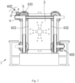
- racks 432 are used to synchronize the transmission of the upper and lower transmission gears 431 on the same side.
- the mould clamping mechanism 41 comprises a mould clamping rod 410 crossing the movable plate 3 and the braking module 430, and a mould clamping cylinder 411 driving the mould clamping rod 410 to drive the movable plate 3 to move transversely.
- the mould clamping rods 41 pass through the braking modules 430, and are fixedly connected to the left end portions of the corresponding connecting rods 12.
- each mould clamping rod 410 is provided with an extending groove b extending along the length direction of the mould clamping rod 410, and an engaging groove c located at the outer periphery of the mould clamping rod 410 and communicated with the extending groove b.
- the extending grooves b are located on two opposite sides of the mould clamping rods 410, so that the portions of the mould clamping rods 410 that penetrates the brake carriers 430 is flat and the engaging grooves c are located on two opposite sides to the flat.
- the projections a move within the extending grooves b , and the braking modules 43 move linearly relative to the mould clamping rods 410; when braking, the projections a rotate by 90°, and engage the engaging grooves c , and the braking modules 43 are fixed relative to the mould clamping rods 410.
- the advantage of this configuration is that the movable plate can move to a set position normally before braking, and when braking, the whole braking process is simple and fast.
- the projections a are in the shape of spiral, and the engaging grooves c fit with them.
- each mould transferring mechanism 40 has a screw rod 400 extending along the length direction of the mould clamping rod 410 and passing through the connecting lug e , a nut 401 fitting with the screw 400 and connected to the connecting lug e , and a driving part 402 driving the nut 401 to rotate, wherein the nut 401 is connected to the connecting lug e via an external connector.
- the advantage of this configuration is that through the fitting of the screws and the gears, the transmission are more stable and reliable.
- each driving part 402 comprises a first gear d arranged on the outer periphery of the nut 401, a motor m arranged on the connecting lug e , and a second gear f connecting a motor output shaft s to the first gear d in a transmission way.
- each braking auxiliary mechanism 42 comprises a clutch h arranged on the outer periphery of the brake carrier 430.
- the clutches h are arranged one to one corresponding to the mould transferring mechanisms 40, and have a first mode and a second mode, and when the clutches h are in the first mode, the braking gears 433 are connected to the first gears d in a transmission way; and when in the second mode, the braking gears 433 are disengaged from the first gears d .
- the specific configuration of the clutches h is not described specifically, the main reason for this is that the clutches are purchased parts, and it is easy to implement the switch between the engagement and disengagement of the braking gears 433 and the first gears d corresponding to the clutch state of the clutch, therefore, it will not be described here.
- the mould clamping cylinders stop the tensioning action and the motors rotate reversely, then the clutches work to make the braking gears engage the first gears again, and when the braking gears rotate reversely by 90° and the projections are staggered with the engaging grooves, the clutches make the braking gears staggered with the first gears, and the nuts drive the movable plate to move back along the length of the screws.
- this embodiment has advantages as follows: this embodiment uses the brake auxiliary mechanism to link the mould transferring mechanism with the brake mechanism to quickly link mould transfer and mould clamping operations, such that the process is simple and rapid, and the positioning accuracy of mould and the repeatability of mould opening and closing can be effectively improved, and additionally, the idle cycle period (dry cycle) of the injection moulding machine itself is also shortened.
Landscapes
- Engineering & Computer Science (AREA)
- Manufacturing & Machinery (AREA)
- Mechanical Engineering (AREA)
- Moulds For Moulding Plastics Or The Like (AREA)
- Injection Moulding Of Plastics Or The Like (AREA)
Abstract
Description
- The present disclosure belongs to the field of mould opening and closing equipment, and specifically relates to an electric mould opening and closing system for a two-plate injection moulding machine.
- At present, mould closing process of a two-plate injection moulding machine generally adopts hydraulic transmission, wherein the mould closing process includes mould transferring process and clamping process (also known as braking), specifically, the mould transferring process includes using a mould transferring cylinder to push a mould plate to move, through position control, stopping the mould transferring cylinder after reaching a braking position, driving a brake plate via a braking cylinder to close, and fixing it on the thread of a pull rod of a high-pressure cylinder, and then clamping the mould through the high-pressure cylinder.
- Clearly, the above mould closing process has the following defects:
- 1), the accuracy of the mould transferring cylinder is restricted, and as a result, it also reduces the mould positioning accuracy and mould opening and closing repeatability;
- 2) the opening and closing of the mould transferring cylinder and the brake plate are implemented separately and independently during the mould closing process, thus increasing the idle cycle period (dry cycle) of the injection moulding machine itself.
- The technical problem to be solved by the present application is to overcome the deficiencies of the prior art, and an improved electric mould opening and closing system for a two-plate injection moulding machine is provide.
- To solve the above technical problems, a technical solution employed by the present disclosure is as follows:
- an electric mould opening and closing system for a two-plate injection moulding machine, comprises a body, a fixed plate, a movable plate, and a mould opening and closing driving device, wherein the mould opening and closing driving device comprises a mould transferring mechanism for driving the movable plate to move forward and backward in a horizontal direction relative to the fixed plate, a brake mechanism for driving a braking nut on the movable plate to lock, and a mould clamping mechanism for locking the movable plate, in particular,
- the mould opening and closing driving device further comprises a brake auxiliary mechanism having a first state and a second state,
- when opening or closing mould, driven by the mould transferring mechanism, the brake auxiliary mechanism and the mould transferring mechanism make the movable plate move forward or backward in a horizontal direction, and the mould transferring mechanism is separated from the mould clamping mechanism by the brake auxiliary mechanism, and the brake auxiliary mechanism is in the first state;
- when braking, a linkage is formed between the brake mechanism and the mould transferring mechanism, the brake auxiliary mechanism is in the second state, and the mould clamping mechanism locks the movable plate tightly.
- Preferably, a braking module rotating around a moving direction of the movable plate is formed on the movable plate, and the mould clamping mechanism comprises a mould clamping rod crossing the movable plate and the braking module, and a mould clamping power unit driving the mould clamping rod to drive the movable plate to move transversely, and when opening or closing mould, the braking module moves linearly relative to the mould clamping rod; and when braking, the braking module is fixed relative to the mould clamping rod.
- According to a specific implementation and preferred aspect of the present disclosure, a first fitting part and a second fitting part are formed on an outer periphery of the mould clamping rod and an inner wall of the braking module respectively, when closing mould, the first fitting part and the second fitting part are staggered with each other, and the braking module moves linearly relative to the mould clamping rod; when braking, the first fitting part and the second fitting part are engaged with each other, and the braking module is fixed relative to the mould clamping rod. The advantage of this configuration is that the movable plate can move to a set position normally before braking, and when braking, the whole braking process is simple and fast.
- Specifically, the first fitting part is a fitting groove recessed inward from the outer periphery of the mould clamping rod; the second fitting part is a fitting projection formed on the inner wall of the braking module, when closing mould, the fitting projection moves within the fitting groove; when braking, the fitting projection and the fitting groove are engaged with each other. The fitting groove comprises an extending groove extending along a length direction of the mould clamping rod, and an engaging groove located at the outer periphery of the mould clamping rod and communicated with the extending groove, and the fitting projection is engaged with the engaging groove when braking.
- According to another specific implementation and preferred aspect of the present disclosure, there are four groups of braking modules, which are arranged square in shape on the movable plate, and mould clamping mechanisms one-to-one corresponding to the braking modules are provided.
- Specifically, each braking module has a brake carrier rotatably connected to the movable plate, and a transmission gear arranged on an outer periphery of the brake carrier, wherein two transmission gears of two braking modules on the same side are synchronously connected via a rack; there are two braking auxiliary mechanisms arranged on two braking modules on a diagonal of the square, wherein each braking auxiliary mechanism comprises a clutch part arranged on the outer periphery of the brake carrier, the clutch part has a first mode and a second mode, and when in the first mode, the mould transferring mechanism is connected to the braking modules in a transmission way; and when in the second mode, the mould transferring mechanism is disengaged from the braking modules.
- According to yet another specific implementation and preferred aspect of the present disclosure, the outer peripheries of the brake carriers are further provided with braking gears, and mould transferring mechanisms one-to-one corresponding to the clutch parts are provided, each mould transferring mechanism has a screw rod extending along the length direction of the mould clamping rod, said nut fitting the screw rod, and a driving part driving the nut to rotate, wherein connecting lugs are fixedly provided on opposite sides of the movable plate, each screw rod passes through one of the connecting lugs, and each nut is connected to one of the connecting lugs via an external connector. The advantage of this configuration is that through the fitting of the screws and the gears, the transmission are more stable and reliable.
- Specifically, each driving part comprises a first gear arranged on an outer periphery of the nut, a motor arranged on the connecting lug, and a second gear connecting a motor output shaft to the first gear in a transmission way, and when closing the mould, the first gear and the braking gear are staggered with each other; when braking, the braking gear is engaged with or separated from the first gear with each other as the movement of the clutch part.
- In addition, the body comprises an underframe, a tail frame arranged on an end portion of the underframe away from the movable plate; a plurality of connecting rods with end portions fixed on the mould clamping rod and another end portions fixed with the tail frame; and a sliding rail arranged on the underframe and extending along the length direction of the mould clamping rod, wherein mould clamping rods one-to-one corresponding to the connecting rods are provided, the movable plate and the tail frame are slidably arranged at the bottom on the sliding rail, the screw rods are connected at one end portion to the tail frame or the screw rods are connected to the mould clamping rods.
- Due to the implementation of the above technical solutions, the present disclosure has the following advantages over the conventional art:
the present disclosure uses the brake auxiliary mechanism to link the mould transferring mechanism with the brake mechanism to quickly link mould transferring and mould clamping operations, such that the process is simple and rapid, and the positioning accuracy of mould and the repeatability of mould opening and closing can be effectively improved, and additionally, the idle cycle period (dry cycle) of the injection moulding machine itself is also shortened. -
-
Fig. 1 is a schematic diagram of an electric mould opening and closing system for a two-plate injection moulding machine of the present disclosure; -
Fig. 2 is a right-side view ofFig. 1 ; -
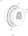
Fig. 3 is a schematic diagram of the braking module shown inFig. 1 . -
- 1 - body; 10 - underframe; 11 - tail frame; 12 - connecting rod; 13 - sliding rail;
- 2 - fixed plate;
- 3 - movable plate; e - connecting lug;
- 4 - opening and closing driving device; 40 - mould transferring mechanism; 400 - screw rod; 401 - nut; d - first gear; 402 - driving part; m - motor; s - motor output shaft; f - second gear; 41 - mould clamping mechanism; 410 - mould clamping rod; b - extending groove; c - engaging groove; 411 - mould clamping cylinder; 42 - braking auxiliary mechanism; h - clutch; 43 - braking module; 430 - brake carrier; 431 - transmission gear; 432 - rack; 433 - braking gear; a - projection.
- In order to make the above objects, features and advantages of the present application more clearly understood, the present application will be described in detail below with reference to the accompanying drawings and specific embodiments. In the following description, numerous specific details are set forth in order to provide a thorough understanding of the present application. However, the present application can be implemented in many other ways different from those described herein, and those skilled in the art can make similar improvements without departing from the connotation of the present application, therefore, the present application is not limited by the specific embodiments disclosed below.
- In the description of the present application, it should be noted that the orientation or positional relationship indicated by the terms "center", "longitudinal direction", "transverse direction", "length", "width", "thickness", "up", "down", "front", "rear", "left", "right", "vertical", "horizontal", "top", "bottom", "inner", "outer", "clockwise", "anticlockwise", "axial direction", "radial direction", "circumferential direction" and the like is based on the orientation or positional relationship shown in the accompanying drawings, is only for the convenience of describing the present application and simplifying the description, rather than indicating or implying that the indicated device or element must have a particular orientation, be constructed and operate in a particular orientation, and therefore should not be construed as limiting the present application.
- Furthermore, the terms "first" and "second" are used for descriptive purposes only and should not be construed to indicate or imply relative importance, or implicitly indicate the number of technical features indicated. Therefore, the features defined with "first" and "second" may explicitly or implicitly include at least one such feature. In the description of the present application, "a plurality of means at least two, such as two, three, etc., unless otherwise expressly and specifically defined.
- In the present disclosure, unless otherwise expressly specified and limited, the terms "arrange", "contact", "connect", "fix" and other terms should be understood in a broad sense, for example, it may be fixedly connected or detachably connected, or integrated; it may be mechanically connected or electrically connected; it can be directly connected or indirectly connected through an intermediate medium, or it can be the internal communication of two elements or the interaction relationship between two elements. For those of ordinary skill in the art, the specific meanings of the above terms in the present disclosure can be understood according to specific situations.
- In the disclosure, unless otherwise expressly specified and limited, a first feature "on" or "under" a second feature may mean that the first feature is in direct contact with the second feature, or the first feature is in indirect contact with the second feature through an intermediate medium. Also, the first feature being "on", "above", "over" the second feature may mean that the first feature is directly above or obliquely above the second feature, or simply means that the first feature is level higher than the second feature. The first feature being "under", "below" and "underneath" the second feature may mean that the first feature is directly below or obliquely below the second feature, or simply means that the first feature has a lower level than the second feature.
- It should be noted that when an element is referred to as being "fixed on" or "disposed on" another element, it can be directly on the other element or intervening elements may also be present. When an element is referred to as being "connected to "another element, it can be directly connected to the other element or intervening elements may also be present. The terms "vertical", "horizontal", "up", "down", "left", "right" and similar expressions used herein are for illustrative purposes only and are not meant to be the only implementation.
- As shown in
Fig. 1 , an electric mould opening and closing system for a two-plate injection moulding machine of this embodiment comprises abody 1, afixed plate 2, amovable plate 3, and a mould opening and closing driving device 4. - Specifically, the
body 1 comprises anunderframe 10, atail frame 11 arranged on a right end of theunderframe 10, four connectingrods 12 fixed on thetail frame 11 at their right end portions and extending horizontally, and a slidingrail 13 arranged on theunderframe 10 and extending along a length direction of the connectingrods 12. - The
fixed plate 2 is fixedly arranged on a left end portion of theunderframe 10 away from thetail frame 11 at the bottom. - The
movable plate 3 is slidably arranged on the slidingrail 13 at the bottom, and connecting lugs e are fixedly provided on opposite sides of themovable plate 3. - The
tail frame 11 is slidably arranged on the slidingrail 13 at the bottom. - Combining with
Fig. 2 , the mould opening and closing driving device 4 comprises amould transferring mechanism 40 for driving themovable plate 3 to move transversely relative to thefixed plate 2, amould clamping mechanism 41 for driving the braking and clamping of themovable plate 3 relative to thefixed plate 2, a braking auxiliary mechanism 42, and abraking module 43 formed on themovable plate 3 and rotating around a moving direction of themovable plate 3. There are four groups ofbraking modules 43, which are arranged square in shape on themovable plate 3. - Combining with
Fig. 3 , eachbraking module 43 has abrake carrier 430 rotatably connected to themovable plate 3, and atransmission gear 431 and abraking gear 433 arranged on the outer periphery of thebrake carrier 430, wherein thebrake carrier 430 is in the shape of a hollow column, and is provided with two groups of opposite projections a on the inner wall, each group of projections a is distributed in an array along the axial direction of thebrake carrier 430. - In order to realize the synchronous movement of two groups, namely upper and lower groups of
brake modules 43,racks 432 are used to synchronize the transmission of the upper andlower transmission gears 431 on the same side. - The
mould clamping mechanism 41 comprises amould clamping rod 410 crossing themovable plate 3 and thebraking module 430, and amould clamping cylinder 411 driving themould clamping rod 410 to drive themovable plate 3 to move transversely. - In this embodiment, there are four groups of
mould clamping mechanisms 41, which are one-to-one corresponding to the four groups ofbraking modules 43. - The
mould clamping rods 41 pass through thebraking modules 430, and are fixedly connected to the left end portions of the corresponding connectingrods 12. - Specifically, each
mould clamping rod 410 is provided with an extending groove b extending along the length direction of themould clamping rod 410, and an engaging groove c located at the outer periphery of themould clamping rod 410 and communicated with the extending groove b. - In this embodiment, the extending grooves b are located on two opposite sides of the
mould clamping rods 410, so that the portions of themould clamping rods 410 that penetrates thebrake carriers 430 is flat and the engaging grooves c are located on two opposite sides to the flat. When closing the mould, the projections a move within the extending grooves b, and thebraking modules 43 move linearly relative to themould clamping rods 410; when braking, the projections a rotate by 90°, and engage the engaging grooves c, and thebraking modules 43 are fixed relative to themould clamping rods 410. The advantage of this configuration is that the movable plate can move to a set position normally before braking, and when braking, the whole braking process is simple and fast. - In this embodiment, the projections a are in the shape of spiral, and the engaging grooves c fit with them.
- In this embodiment, there are two groups of
mould transferring mechanisms 40 , with each arranged on one side of one of the twobraking modules 43 arranged on a diagonal of the square respectively. - Specifically, each
mould transferring mechanism 40 has ascrew rod 400 extending along the length direction of themould clamping rod 410 and passing through the connecting lug e, anut 401 fitting with thescrew 400 and connected to the connecting lug e, and a drivingpart 402 driving thenut 401 to rotate, wherein thenut 401 is connected to the connecting lug e via an external connector. The advantage of this configuration is that through the fitting of the screws and the gears, the transmission are more stable and reliable. In this embodiment, thescrew rods 400 are connected to thetail frame 11 at their right end portions; each drivingpart 402 comprises a first gear d arranged on the outer periphery of thenut 401, a motor m arranged on the connecting lug e, and a second gear f connecting a motor output shaft s to the first gear d in a transmission way. - In this embodiment, there are two braking auxiliary mechanisms 42 arranged on two
braking modules 43 on a diagonal of the square respectively, wherein each braking auxiliary mechanism 42 comprises a clutch h arranged on the outer periphery of thebrake carrier 430. - Specifically, the clutches h are arranged one to one corresponding to the
mould transferring mechanisms 40, and have a first mode and a second mode, and when the clutches h are in the first mode, the braking gears 433 are connected to the first gears d in a transmission way; and when in the second mode, the braking gears 433 are disengaged from the first gears d. In this embodiment, although the specific configuration of the clutches h is not described specifically, the main reason for this is that the clutches are purchased parts, and it is easy to implement the switch between the engagement and disengagement of the braking gears 433 and the first gears d corresponding to the clutch state of the clutch, therefore, it will not be described here. - In summary, the implementation process of this embodiment is as follows:
- when closing the mould, the motors drive through the gears by engaged transmission to make the nuts on the screws rotate and move in the direction of the length of the screws, which in turn pushes the connecting lugs fixed on the movable plate to move forward, so that the movable plate moves closer to the fixed plate until it moves to the set position to complete the closing of the mould;
- when braking, the clutches operate, the braking gears arranged on the brake carriers engage the first gears on the nuts, and the braking gears rotate by 90°, so that the projections on the inner wall of the brake carriers engage the engaging grooves on the mould clamping rods, and the mould clamping cylinders operate to lock tightly, and the clutches operate again to disengage the braking gears from the first gears and complete the braking process.
- As for opening the mould, the mould clamping cylinders stop the tensioning action and the motors rotate reversely, then the clutches work to make the braking gears engage the first gears again, and when the braking gears rotate reversely by 90° and the projections are staggered with the engaging grooves, the clutches make the braking gears staggered with the first gears, and the nuts drive the movable plate to move back along the length of the screws.
- Therefore, this embodiment has advantages as follows:
this embodiment uses the brake auxiliary mechanism to link the mould transferring mechanism with the brake mechanism to quickly link mould transfer and mould clamping operations, such that the process is simple and rapid, and the positioning accuracy of mould and the repeatability of mould opening and closing can be effectively improved, and additionally, the idle cycle period (dry cycle) of the injection moulding machine itself is also shortened. - The above detailed describes the present disclosure, and is intended to make those skilled in the art being able to understand the present disclosure and thereby implement it, and should not be concluded to limit the protective scope of this disclosure. Any equivalent variations or modifications according to the spirit of the present disclosure should be covered by the protective scope of the present disclosure.
Claims (13)
- An electric mould opening and closing system for a two-plate injection moulding machine, comprising a body, a fixed plate, a movable plate, and a mould opening and closing driving device, wherein the mould opening and closing driving device comprises a mould transferring mechanism for driving the movable plate to move back and forth in a horizontal direction relative to the fixed plate, a brake mechanism for driving a braking nut on the movable plate to lock, and a mould clamping mechanism for locking the movable plate, characterized in that,the mould opening and closing driving device further comprises a brake auxiliary mechanism having a first state and a second state,when opening or closing mould, driven by the mould transferring mechanism, the brake auxiliary mechanism and the mould transferring mechanism make the movable plate move forward or backward in a horizontal direction, and the mould transferring mechanism is separated from the mould clamping mechanism by the brake auxiliary mechanism, and the brake auxiliary mechanism is in the first state;when braking, a linkage is formed between the brake mechanism and the mould transferring mechanism, the brake auxiliary mechanism is in the second state, and the mould clamping mechanism locks the movable plate tightly;a braking module rotating around a moving direction of the movable plate is formed on the movable plate, and the mould clamping mechanism comprises a mould clamping rod crossing the movable plate and the braking module, and a mould clamping power unit driving the mould clamping rod to drive the movable plate to move transversely, and when opening and closing mould, the braking module moves linearly relative to the mould clamping rod; and when braking, the braking module is fixed relative to the mould clamping rod;a first fitting part and a second fitting part are formed on an outer periphery of the mould clamping rod and an inner wall of the braking module respectively, when closing mould, the first fitting part and the second fitting part are staggered with each other, and the braking module moves linearly relative to the mould clamping rod; when braking, the first fitting part and the second fitting part are engaged with each other, and the braking module is fixed relative to the mould clamping rod;the first fitting part is a fitting groove recessed inward from the outer periphery of the mould clamping rod; the second fitting part is a fitting projection formed on the inner wall of the braking module, wherein when closing mould, the fitting projection moves in the fitting groove; when braking, the fitting projection and the fitting groove are engaged with each other;the fitting groove comprises an extending groove extending along a length direction of the mould clamping rod, and an engaging groove located at the outer periphery of the mould clamping rod and communicated with the extending groove, and the fitting projection is engaged with the engaging groove when braking;there are four groups of braking modules, which are arranged square in shape on the movable plate, and mould clamping mechanisms one-to-one corresponding to the braking modules are provided;each braking module has a brake carrier rotatably connected to the movable plate, and a transmission gear arranged on an outer periphery of the brake carrier, wherein two transmission gears of two braking modules on the same side are synchronously connected via a rack;there are two braking auxiliary mechanisms arranged on two braking modules on a diagonal of the square, wherein each braking auxiliary mechanism comprises a clutch part arranged on the outer periphery of the brake carrier, wherein the clutch part has a first mode and a second mode, and when in the first mode, the mould transferring mechanism is connected to the braking modules in a transmission way; and when in the second mode, the mould transferring mechanism is disengaged from the braking modules.the outer peripheries of the brake carriers are further provided with braking gears, mould transferring mechanisms one-to-one corresponding to the clutch parts are provided, each mould transferring mechanism has a screw rod extending along the length direction of the mould clamping rod, a nut fitting the screw rod, and a driving part driving the nut to rotate, wherein connecting lugs are fixedly provided on opposite sides of the movable plate, each screw rod passes through one of the connecting lugs, and each nut is connected to one of the connecting lugs via an external connector;each driving part comprises a first gear arranged on an outer periphery of the nut, a motor arranged on the connecting lug, and a second gear connecting a motor output shaft to the first gear in a transmission way, and when opening or closing mould, the first gear and the braking gear are staggered with each other; and when braking, the braking gear is engaged with or separated from the first gear with each other as the movement of the clutch part.the body comprises an underframe, a tail frame arranged on an end portion of the underframe away from the movable plate; a plurality of connecting rods with end portions fixed on the mould clamping rod and another end portions fixed with the tail frame; and a sliding rail arranged on the underframe and extending along the length direction of the mould clamping rod, wherein mould clamping rods one-to-one corresponding to the connecting rods are procided, the movable plate and the tail frame are slidably arranged at the bottom on the sliding rail, the screw rods are connected at one end portion to the tail frame or the screw rods are connected to the mould clamping rods.
- An electric mould opening and closing system for a two-plate injection moulding machine, comprising a body, a fixed plate, a movable plate, and a mould opening and closing driving device, wherein the mould opening and closing driving device comprises a mould transferring mechanism for driving the movable plate to move back and forth in a horizontal direction relative to the fixed plate, a brake mechanism for driving a braking nut on the movable plate to lock, and a mould clamping mechanism for locking the movable plate, characterized in that,the mould opening and closing driving device further comprises a brake auxiliary mechanism having a first state and a second state,when opening or closing the mould, driven by the mould transferring mechanism, the brake auxiliary mechanism and the mould transferring mechanism make the movable plate move forward or backward in a horizontal direction, and the mould transferring mechanism is separated from the mould clamping mechanism by the brake auxiliary mechanism, and the brake auxiliary mechanism is in the first state;when braking, a linkage is formed between the brake mechanism and the mould transferring mechanism, the brake auxiliary mechanism is in the second state, and the mould clamping mechanism locks the movable plate tightly.
- The electric mould opening and closing system for a two-plate injection moulding machine according to claim 2, characterized in that, a braking module rotating around a moving direction of the movable plate is formed on the movable plate,the mould clamping mechanism comprises a mould clamping rod crossing the movable plate and the braking module, and a mould clamping power unit driving the mould clamping rod to drive the movable plate to move transversely,when opening or closing mould, the braking module moves linearly relative to the mould clamping rod;when braking, the braking module is fixed relative to the mould clamping rod.
- The electric mould opening and closing system for a two-plate injection moulding machine according to claim 3, characterized in that, a first fitting part and a second fitting part are formed on an outer periphery of the mould clamping rod and an inner wall of the braking module respectively, when closing mould, the first fitting part and the second fitting part are staggered with each other, and the braking module moves linearly relative to the mould clamping rod; when braking, the first fitting part and the second fitting part are engaged with each other, and the braking module is fixed relative to the mould clamping rod.
- The electric mould opening and closing system for a two-plate injection moulding machine according to claim 4, characterized in that, the first fitting part is a fitting groove recessed inward from the outer periphery of the mould clamping rod; the second fitting part is a fitting projection formed on the inner wall of the braking module, when closing mould, the fitting projection moves within the fitting groove; when braking, the fitting projection and the fitting groove are engaged with each other.
- The electric mould opening and closing system for a two-plate injection moulding machine according to claim 5, characterized in that, the fitting groove comprises an extending groove extending along a length direction of the mould clamping rod, and an engaging groove located at the outer periphery of the mould clamping rod and communicated with the extending groove, and the fitting projection is engaged with the engaging groove when braking.
- The electric mould opening and closing system for a two-plate injection moulding machine according to claim 3, characterized in that, there are four groups of braking modules, which are arranged square in shape on the movable plate, and mould clamping mechanisms one-to-one corresponding to the braking modules are provided.
- The electric mould opening and closing system for a two-plate injection moulding machine according to claim 7, characterized in that, each braking module has a brake carrier rotatably connected to the movable plate, and a transmission gear arranged on an outer periphery of the brake carrier, wherein two transmission gears of two braking modules on the same side are synchronously connected via a rack.
- The electric mould opening and closing system for a two-plate injection moulding machine according to claim 8, characterized in that, there are two braking auxiliary mechanisms arranged on two braking modules on a diagonal of the square, wherein each braking auxiliary mechanism comprises a clutch part arranged on the outer periphery of the brake carrier, wherein the clutch part has a first mode and a second mode, and when in the first mode, the mould transferring mechanism is connected to the braking modules in a transmission way; and when in the second mode, the mould transferring mechanism is disengaged from the braking modules.
- The electric mould opening and closing system for a two-plate injection moulding machine according to claim 9, characterized in that, the outer peripheries of the brake carriers are further provided with braking gears, and mould transferring mechanisms one-to-one corresponding to the clutch parts are provided
- The electric mould opening and closing system for a two-plate injection moulding machine according to claim 10, characterized in that, each mould transferring mechanism has a screw rod extending along the length direction of the mould clamping rod, said nut fitting the screw rod, and a driving part driving the nut to rotate, wherein connecting lugs are fixedly provided on opposite sides of the movable plate, each screw rod passes through one of the connecting lugs, and each nut is connected to one of the connecting lugs via an external connector.
- The electric mould opening and closing system for a two-plate injection moulding machine according to claim 11, characterized in that, each driving part comprises a first gear arranged on an outer periphery of the nut, a motor arranged on the connecting lug, and a second gear connecting a motor output shaft to the first gear in a transmission way, and when opening or closing mould, the first gear and the braking gear are staggered with each other; and when braking, the braking gear is engaged with or separated from the first gear with each other as the movement of the clutch part.
- The electric mould opening and closing system for a two-plate injection moulding machine according to claim 8, characterized in that, the body comprises an underframe, a tail frame arranged on an end portion of the underframe away from the movable plate; a plurality of connecting rods with end portions fixed on the mould clamping rod and another end portions fixed on the tail frame; and a sliding rail arranged on the underframe and extending along the length direction of the mould clamping rod, wherein mould clamping rods one-to-one corresponding to the connecting rods are provided, the movable plate and the tail frame are slidably arranged at the bottom on the sliding rail, the screw rods are connected at one end portion to the tail frame or the screw rods are connected to the mould clamping rods.
Applications Claiming Priority (2)
| Application Number | Priority Date | Filing Date | Title |
|---|---|---|---|
| CN202010943740.4A CN112140486B (en) | 2020-09-09 | 2020-09-09 | Electric mold opening and closing system for two-platen injection molding machine |
| PCT/CN2020/136094 WO2022052351A1 (en) | 2020-09-09 | 2020-12-14 | Electric mold opening and closing system of two-platen injection molding machine |
Publications (4)
| Publication Number | Publication Date |
|---|---|
| EP4212308A1 true EP4212308A1 (en) | 2023-07-19 |
| EP4212308A4 EP4212308A4 (en) | 2024-08-28 |
| EP4212308C0 EP4212308C0 (en) | 2026-01-28 |
| EP4212308B1 EP4212308B1 (en) | 2026-01-28 |
Family
ID=73889430
Family Applications (1)
| Application Number | Title | Priority Date | Filing Date |
|---|---|---|---|
| EP20953136.7A Active EP4212308B1 (en) | 2020-09-09 | 2020-12-14 | Electric mold opening and closing system of two-platen injection molding machine |
Country Status (5)
| Country | Link |
|---|---|
| US (1) | US12447657B2 (en) |
| EP (1) | EP4212308B1 (en) |
| JP (1) | JP7513998B2 (en) |
| CN (1) | CN112140486B (en) |
| WO (1) | WO2022052351A1 (en) |
Families Citing this family (4)
| Publication number | Priority date | Publication date | Assignee | Title |
|---|---|---|---|---|
| CN112659494B (en) * | 2021-01-29 | 2025-05-23 | 苏州锦珂塑胶科技有限公司 | Two-platen injection molding machine with electric mold opening and closing |
| CN115071082B (en) * | 2022-04-29 | 2023-09-19 | 宁波长飞亚塑料机械制造有限公司 | Micro-die opening system for realizing correlation injection molding machine and control method thereof |
| CN118990937B (en) * | 2024-09-26 | 2025-10-17 | 广东星联精密机械有限公司 | Blank injection mold with optimized mold opening and closing actions |
| CN119189203B (en) * | 2024-11-26 | 2025-07-04 | 苏州双荣橡塑有限公司 | Auxiliary device for preparing injection molding equipment of automobile window-swinging bracket assembly and application |
Family Cites Families (27)
| Publication number | Priority date | Publication date | Assignee | Title |
|---|---|---|---|---|
| CA1196458A (en) * | 1981-10-08 | 1985-11-12 | Yoshihiko Yamazaki | Injection molding machine |
| JPH0622828B2 (en) * | 1986-06-30 | 1994-03-30 | フアナツク株式会社 | Direct pressure type mold clamping mechanism |
| LU88623A1 (en) | 1995-06-12 | 1997-01-03 | Wurth Paul Sa | Closing unit for an injection molding machine |
| JP3240275B2 (en) * | 1997-09-08 | 2001-12-17 | 東芝機械株式会社 | Mold clamping device of injection molding machine |
| JP2000246776A (en) | 1999-02-26 | 2000-09-12 | Toshiba Mach Co Ltd | Composite mold clamping device |
| US6186770B1 (en) * | 1999-03-05 | 2001-02-13 | Amir Ziv-Av | Clamping assembly for injection molding apparatus |
| AU2231701A (en) * | 1999-12-28 | 2001-07-09 | Ube Machinery Corporation, Ltd. | Mold clamping device, method of increasing/decreasing pressure for such device, and mold releasing method |
| JP2002200658A (en) | 2000-12-28 | 2002-07-16 | Mitsubishi Heavy Ind Ltd | Mold clamping device for injection molding machine |
| JP2003181894A (en) | 2001-10-12 | 2003-07-02 | Meiki Co Ltd | Mold clamping device and joining position adjusting method therfor |
| US20040208951A1 (en) | 2003-04-21 | 2004-10-21 | Bealer Kenneth H. | Electric molding clamp assembly |
| DE202004020687U1 (en) * | 2004-10-14 | 2005-11-17 | Krauss-Maffei Kunststofftechnik Gmbh | Injection molding machine for sterile, clean room areas moves on guide tracks to move the tool clamping unit between the sterile room operating position and a servicing position outside this room |
| JP4684675B2 (en) * | 2005-02-15 | 2011-05-18 | 東芝機械株式会社 | Clamping device |
| CN201272011Y (en) * | 2008-09-01 | 2009-07-15 | 夏善海 | Rotating contracting brake mechanism of two-plate injection moulding machine |
| CN102463659B (en) * | 2010-11-14 | 2016-09-14 | 海天塑机集团有限公司 | Electric brake nut adjusting type die closing mechanism |
| AT512311B1 (en) * | 2012-05-25 | 2013-07-15 | Engel Austria Gmbh | Drive device for an injection molding machine |
| CN104552842B (en) * | 2014-12-26 | 2017-06-16 | 中国计量大学 | Self-locking two trigger clamping opens closing method |
| CN104552843A (en) * | 2014-12-31 | 2015-04-29 | 上海光塑机械制造有限公司 | Rotary gate mechanism for two-plate-type injection molding machine |
| CN105172076B (en) * | 2015-09-30 | 2017-03-29 | 博创智能装备股份有限公司 | A kind of clamping mechanism, injection molding apparatus, die-cast formation equipment |
| CN205310732U (en) * | 2016-01-06 | 2016-06-15 | 刘镇江 | Novel two board -like mode lockings device |
| CN207190131U (en) * | 2017-09-20 | 2018-04-06 | 成都市联余精密机械有限公司 | The folded mould special injection molding of injection among a kind of split shifting formwork of template |
| CN108016005A (en) * | 2017-12-28 | 2018-05-11 | 刘镇江 | Double-plate matched mould apparatus |
| CN109263005B (en) * | 2018-10-30 | 2020-01-10 | 珠海格力电器股份有限公司 | Locking mechanism and injection molding machine with same |
| CN209289712U (en) * | 2018-11-15 | 2019-08-23 | 北京化工大学 | A clamping device for a two-platen injection molding machine |
| CN209616279U (en) * | 2019-03-07 | 2019-11-12 | 安徽江澜智能装备有限公司 | A kind of Clamping Device of Injection Moulding Machine |
| CN210116145U (en) * | 2019-07-02 | 2020-02-28 | 宁波力松注塑科技有限公司 | High-precision high-efficiency injection molding machine |
| CN110682510B (en) * | 2019-10-08 | 2025-07-01 | 苏州锦珂塑胶科技有限公司 | High-performance injection molding machine with coordinated plasticizing power and injection power |
| CN213648555U (en) * | 2020-09-09 | 2021-07-09 | 苏州锦珂塑胶科技有限公司 | Electric mold opening and closing system of two-plate injection molding machine |
-
2020
- 2020-09-09 CN CN202010943740.4A patent/CN112140486B/en active Active
- 2020-12-14 JP JP2023515069A patent/JP7513998B2/en active Active
- 2020-12-14 EP EP20953136.7A patent/EP4212308B1/en active Active
- 2020-12-14 WO PCT/CN2020/136094 patent/WO2022052351A1/en not_active Ceased
-
2023
- 2023-03-08 US US18/180,561 patent/US12447657B2/en active Active
Also Published As
| Publication number | Publication date |
|---|---|
| US12447657B2 (en) | 2025-10-21 |
| CN112140486A (en) | 2020-12-29 |
| JP7513998B2 (en) | 2024-07-10 |
| JP2023540345A (en) | 2023-09-22 |
| EP4212308A4 (en) | 2024-08-28 |
| EP4212308C0 (en) | 2026-01-28 |
| US20230219271A1 (en) | 2023-07-13 |
| CN112140486B (en) | 2025-05-13 |
| WO2022052351A1 (en) | 2022-03-17 |
| EP4212308B1 (en) | 2026-01-28 |
Similar Documents
| Publication | Publication Date | Title |
|---|---|---|
| US12447657B2 (en) | Electric mould opening and closing system of injection moulding machine | |
| CN112659494B (en) | Two-platen injection molding machine with electric mold opening and closing | |
| JPH0622822B2 (en) | Injection molding machine | |
| CN205310732U (en) | Novel two board -like mode lockings device | |
| JP3927066B2 (en) | Clamping device | |
| CN213648555U (en) | Electric mold opening and closing system of two-plate injection molding machine | |
| US6592360B2 (en) | Mold clamping apparatus of injection molding machine | |
| CN204525928U (en) | The energy-conservation injection moulding machine of a kind of electric-hydraulic combined formula ultrahigh speed | |
| CN214773808U (en) | Two-plate injection molding machine capable of electrically opening and closing mold | |
| CN201784151U (en) | Die locking device of two-plate pull rod telescopic injection-molding machine | |
| CN220390158U (en) | Wheel casing mould of accurate location | |
| CN210628809U (en) | Power cabinet | |
| CN113001722B (en) | A mold opening and closing mechanism | |
| CN215398541U (en) | Fixing device for vehicle-mounted BMS system controller capable of accommodating connecting wires | |
| JPH0839631A (en) | Injection device of electromotive injection molding machine | |
| CN215512096U (en) | Core-pulling mechanism and pipe bending die using the core-pulling mechanism | |
| US6527536B2 (en) | Mold-thickness adjustment mechanism for toggle type vertical molding machine | |
| CN219338443U (en) | Auxiliary ejection device | |
| JP3728232B2 (en) | Molding device clamping machine | |
| CN216992865U (en) | Vaulting pole band-type brake mechanism of vertical injection molding machine | |
| CN223493762U (en) | A mold structure for a washing machine bellows rubber assembly | |
| CN221271927U (en) | Ejecting rotary transposition structure of double injection molding machine | |
| CN221456642U (en) | Injection mold for plastic tee joint sewer pipeline | |
| CN222946143U (en) | Mould locking mechanism for injection molding of plastic parts | |
| CN213163018U (en) | Die casting machine for producing mechanical parts |
Legal Events
| Date | Code | Title | Description |
|---|---|---|---|
| STAA | Information on the status of an ep patent application or granted ep patent |
Free format text: STATUS: THE INTERNATIONAL PUBLICATION HAS BEEN MADE |
|
| PUAI | Public reference made under article 153(3) epc to a published international application that has entered the european phase |
Free format text: ORIGINAL CODE: 0009012 |
|
| STAA | Information on the status of an ep patent application or granted ep patent |
Free format text: STATUS: REQUEST FOR EXAMINATION WAS MADE |
|
| 17P | Request for examination filed |
Effective date: 20230320 |
|
| AK | Designated contracting states |
Kind code of ref document: A1 Designated state(s): AL AT BE BG CH CY CZ DE DK EE ES FI FR GB GR HR HU IE IS IT LI LT LU LV MC MK MT NL NO PL PT RO RS SE SI SK SM TR |
|
| DAV | Request for validation of the european patent (deleted) | ||
| DAX | Request for extension of the european patent (deleted) | ||
| A4 | Supplementary search report drawn up and despatched |
Effective date: 20240726 |
|
| RIC1 | Information provided on ipc code assigned before grant |
Ipc: B29C 45/66 20060101AFI20240722BHEP |
|
| GRAP | Despatch of communication of intention to grant a patent |
Free format text: ORIGINAL CODE: EPIDOSNIGR1 |
|
| STAA | Information on the status of an ep patent application or granted ep patent |
Free format text: STATUS: GRANT OF PATENT IS INTENDED |
|
| INTG | Intention to grant announced |
Effective date: 20251006 |
|
| GRAS | Grant fee paid |
Free format text: ORIGINAL CODE: EPIDOSNIGR3 |
|
| GRAA | (expected) grant |
Free format text: ORIGINAL CODE: 0009210 |
|
| STAA | Information on the status of an ep patent application or granted ep patent |
Free format text: STATUS: THE PATENT HAS BEEN GRANTED |
|
| AK | Designated contracting states |
Kind code of ref document: B1 Designated state(s): AL AT BE BG CH CY CZ DE DK EE ES FI FR GB GR HR HU IE IS IT LI LT LU LV MC MK MT NL NO PL PT RO RS SE SI SK SM TR |
|
| REG | Reference to a national code |
Ref country code: CH Ref legal event code: F10 Free format text: ST27 STATUS EVENT CODE: U-0-0-F10-F00 (AS PROVIDED BY THE NATIONAL OFFICE) Effective date: 20260128 Ref country code: GB Ref legal event code: FG4D |
|
| REG | Reference to a national code |
Ref country code: DE Ref legal event code: R096 Ref document number: 602020066424 Country of ref document: DE |
|
| REG | Reference to a national code |
Ref country code: IE Ref legal event code: FG4D |
|
| U01 | Request for unitary effect filed |
Effective date: 20260206 |
|
| U07 | Unitary effect registered |
Designated state(s): AT BE BG DE DK EE FI FR IT LT LU LV MT NL PT RO SE SI Effective date: 20260212 |