EP4212030A1 - Atomizer, electronic atomization device, and liquid guide mechanism - Google Patents
Atomizer, electronic atomization device, and liquid guide mechanism Download PDFInfo
- Publication number
- EP4212030A1 EP4212030A1 EP20953087.2A EP20953087A EP4212030A1 EP 4212030 A1 EP4212030 A1 EP 4212030A1 EP 20953087 A EP20953087 A EP 20953087A EP 4212030 A1 EP4212030 A1 EP 4212030A1
- Authority
- EP
- European Patent Office
- Prior art keywords
- liquid guiding
- liquid
- guiding portion
- channel
- guiding channel
- Prior art date
- Legal status (The legal status is an assumption and is not a legal conclusion. Google has not performed a legal analysis and makes no representation as to the accuracy of the status listed.)
- Granted
Links
Images






Classifications
-
- A—HUMAN NECESSITIES
- A24—TOBACCO; CIGARS; CIGARETTES; SIMULATED SMOKING DEVICES; SMOKERS' REQUISITES
- A24F—SMOKERS' REQUISITES; MATCH BOXES; SIMULATED SMOKING DEVICES
- A24F40/00—Electrically operated smoking devices; Component parts thereof; Manufacture thereof; Maintenance or testing thereof; Charging means specially adapted therefor
- A24F40/40—Constructional details, e.g. connection of cartridges and battery parts
- A24F40/44—Wicks
-
- A—HUMAN NECESSITIES
- A24—TOBACCO; CIGARS; CIGARETTES; SIMULATED SMOKING DEVICES; SMOKERS' REQUISITES
- A24F—SMOKERS' REQUISITES; MATCH BOXES; SIMULATED SMOKING DEVICES
- A24F40/00—Electrically operated smoking devices; Component parts thereof; Manufacture thereof; Maintenance or testing thereof; Charging means specially adapted therefor
- A24F40/40—Constructional details, e.g. connection of cartridges and battery parts
-
- A—HUMAN NECESSITIES
- A24—TOBACCO; CIGARS; CIGARETTES; SIMULATED SMOKING DEVICES; SMOKERS' REQUISITES
- A24F—SMOKERS' REQUISITES; MATCH BOXES; SIMULATED SMOKING DEVICES
- A24F40/00—Electrically operated smoking devices; Component parts thereof; Manufacture thereof; Maintenance or testing thereof; Charging means specially adapted therefor
- A24F40/40—Constructional details, e.g. connection of cartridges and battery parts
- A24F40/46—Shape or structure of electric heating means
-
- A—HUMAN NECESSITIES
- A24—TOBACCO; CIGARS; CIGARETTES; SIMULATED SMOKING DEVICES; SMOKERS' REQUISITES
- A24F—SMOKERS' REQUISITES; MATCH BOXES; SIMULATED SMOKING DEVICES
- A24F40/00—Electrically operated smoking devices; Component parts thereof; Manufacture thereof; Maintenance or testing thereof; Charging means specially adapted therefor
- A24F40/40—Constructional details, e.g. connection of cartridges and battery parts
- A24F40/48—Fluid transfer means, e.g. pumps
- A24F40/485—Valves; Apertures
-
- A—HUMAN NECESSITIES
- A24—TOBACCO; CIGARS; CIGARETTES; SIMULATED SMOKING DEVICES; SMOKERS' REQUISITES
- A24F—SMOKERS' REQUISITES; MATCH BOXES; SIMULATED SMOKING DEVICES
- A24F40/00—Electrically operated smoking devices; Component parts thereof; Manufacture thereof; Maintenance or testing thereof; Charging means specially adapted therefor
- A24F40/10—Devices using liquid inhalable precursors
-
- A—HUMAN NECESSITIES
- A24—TOBACCO; CIGARS; CIGARETTES; SIMULATED SMOKING DEVICES; SMOKERS' REQUISITES
- A24F—SMOKERS' REQUISITES; MATCH BOXES; SIMULATED SMOKING DEVICES
- A24F40/00—Electrically operated smoking devices; Component parts thereof; Manufacture thereof; Maintenance or testing thereof; Charging means specially adapted therefor
- A24F40/40—Constructional details, e.g. connection of cartridges and battery parts
- A24F40/42—Cartridges or containers for inhalable precursors
-
- A—HUMAN NECESSITIES
- A24—TOBACCO; CIGARS; CIGARETTES; SIMULATED SMOKING DEVICES; SMOKERS' REQUISITES
- A24F—SMOKERS' REQUISITES; MATCH BOXES; SIMULATED SMOKING DEVICES
- A24F40/00—Electrically operated smoking devices; Component parts thereof; Manufacture thereof; Maintenance or testing thereof; Charging means specially adapted therefor
- A24F40/40—Constructional details, e.g. connection of cartridges and battery parts
- A24F40/48—Fluid transfer means, e.g. pumps
Definitions
- the present disclosure relates to the technical field of electronic atomizing devices, and in particular, to an atomizer, an electronic atomizing device, and a liquid guiding structure.
- An atomizer is a device that atomizes liquid (such as e-liquid) into gases or tiny particles, and is widely used in apparatuses such as medical equipment, or an electronic atomizing device.
- the atomizer generally includes a bottom plate, an atomization base, and an atomization core.
- the atomization base is covered on the bottom plate and cooperates with the bottom plate to form an atomization cavity.
- the atomization core is accommodated in the atomization cavity for heating and atomizing the liquid in the atomization cavity when energized.
- air inlet holes are also defined on the bottom plate, and one end of each air inlet hole is in communication with external air, and the other end is in communication with the atomizer, so that the external air can enter the atomization cavity through the air inlet holes.
- the present disclosure provides an atomizer, an electronic atomizing device, and a liquid guiding structure.
- the atomizer can resolve a problem that a large amount of liquid will accumulate on one side surface of a bottom plate facing an atomization base during use of an existing atomizer, and will leak out from air inlet holes of the bottom plate, resulting in liquid leakage.
- the atomizer includes a bottom plate, an atomization base, an atomization core, and a liquid guiding assembly.
- the bottom plate includes a first surface and a second surface that are arranged oppositely.
- the atomization base is covered on the first surface of the bottom plate and cooperates with the first surface of the bottom plate to form an atomization cavity.
- the atomization core is accommodated in the atomization cavity for heating and atomizing liquid in the atomization cavity when energized.
- the liquid guiding assembly is configured to absorb liquid on the bottom plate, the liquid guiding assembly includes a first liquid guiding portion and a second liquid guiding portion.
- the first liquid guiding portion is arranged on the first surface of the bottom plate and cooperates with the first surface of the bottom plate to form at least one first liquid guiding channel; and the second liquid guiding portion includes at least one second liquid guiding channel, and one end of the second liquid guiding channel is in communication with the first liquid guiding channel.
- the transverse dimension of the first liquid guiding channel decreases gradually in the direction toward the second liquid guiding portion, and a capillary force of the second liquid guiding channel is greater than that of the first liquid guiding channel, liquid absorbed by the first liquid guiding portion by the capillary force of the first liquid guiding channel is guided to the second liquid guiding portion.
- the electronic atomizing device includes an atomizer and a power supply component, the atomizer is the atomizer mentioned above and is configured to heat and atomize liquid when energized, and the power supply component is connected to the atomizer and is configured to supply power to the atomizer.
- the liquid guiding structure includes a base and a liquid guiding assembly.
- the base includes a first surface and a second surface arranged oppositely.
- the liquid guiding assembly is configured to absorb liquid on the base, the liquid guiding assembly includes a first liquid guiding portion and a second liquid guiding portion.
- the first liquid guiding portion is arranged on the first surface of the base and cooperates with the base to form at least one first liquid guiding channel; and the second liquid guiding portion includes at least one second liquid guiding channel, and one end of the second liquid guiding channel is in communication with the first liquid guiding channel, the transverse dimension of the first liquid guiding channel decreases gradually in the direction toward the second liquid guiding portion, and a capillary force of the second liquid guiding channel is greater than a capillary force of the first liquid guiding channel, liquid absorbed by the first liquid guiding portion by the capillary force of the first liquid guiding channel is guide to the second liquid guiding portion.
- the present disclosure provides an atomizer, an electronic atomizing device, and a liquid guiding structure.
- the atomizer includes the bottom plate, by arranging the bottom plate and arranging the first liquid guiding portion on the first surface of the bottom plate, the first liquid guiding portion cooperates with the first surface of the bottom plate to form at least one first liquid guiding channel.
- the second liquid guiding portion is arranged on the first surface of the bottom plate, at least one second liquid guiding channel is defined on the second liquid guiding portion, one end of the second liquid guiding channel is in communication with the first liquid guiding channel, and the transverse dimension of the first liquid guiding channel gradually decreases in the direction toward the second liquid guiding portion.
- the capillary force of the first liquid guiding channel increases gradually in the direction toward the second liquid guiding portion, and the gradually increasing capillary force is used to absorb and guide the liquid on the first surface of the bottom plate.
- the capillary force of the second liquid guiding channel is greater than the capillary force of the first liquid guiding channel, so that the liquid absorbed by the first liquid guiding portion by the capillary force of the first liquid guiding channel is guided to the second liquid guiding portion. Therefore, the liquid on the bottom plate is stored to greatly reduce the probability of liquid leakage of the atomizer.
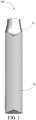
- FIG. 1 is a schematic structural view of an electronic atomizing device according to an embodiment of the present disclosure.
- FIG. 2a is a schematic structural view of an atomizer according to an embodiment of the present disclosure.
- FIG. 2b is a schematic view of a local structure of A in FIG. 2a .
- FIG. 3a is a schematic structural view of an atomization base according to a first embodiment of the present disclosure.
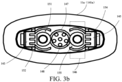
- FIG. 3b is a top view of FIG. 3a .
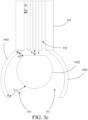
- FIG. 3c is a schematic plan view of a first liquid guiding portion and a second liquid guiding portion according to an embodiment of the present disclosure.
- FIG. 4a is a schematic structural view of an atomization base according to a second embodiment of the present disclosure.
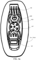
- FIG. 4b is a top view of FIG. 4a .
- FIG. 5a is a schematic structural view of an atomization base according to a third embodiment of the present disclosure.
- FIG. 5b is a top view of FIG. 5a .
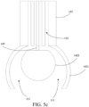
- FIG. 5c is a schematic plan view of a first liquid guiding portion and a second liquid guiding portion according to another embodiment of the present disclosure.
- FIG. 6 is a top view of an atomization base according to an embodiment of the present disclosure.
- FIG. 7 is a schematic plan view of a first liquid guiding portion, a second liquid guiding portion, and a third liquid guiding portion according to an embodiment of the present disclosure.
- first”, “second”, and “third” in the present disclosure are used for descriptive purposes only and should not be construed as indicating or implying relative importance or implicitly indicating the number of technical features indicated. Therefore, a feature defined by “first”, “second”, or “third” may explicitly indicate or implicitly include at least one of the features.
- "a plurality of” means at least two, for example, two or three. All directional indications (for example, up, down, left, right, front, back%) in the embodiments of the present disclosure are only used for explaining relative position relationships, movement situations, or the like between various components in a posture (as shown in the accompanying drawings). If the posture changes, the directional indications change accordingly.
- a process, method, system, product, or device that includes a series of operations or units is not limited to the listed operations or units; and instead, optionally includes an operation or unit that is not listed, or optionally includes another operation or unit that is intrinsic to the process, method, product, or device.
- FIG. 1 is a schematic structural view of an electronic atomizing device according to an embodiment of the present disclosure.
- an electronic atomizing device 100 is provided.
- the electronic atomizing device 100 may be configured to heat and atomize cigarette liquid to form smoke for a user to inhale.
- the electronic atomizing device 100 may be an e-cigarette, and the cigarette liquid may be e-liquid.
- the electronic atomizing device 100 includes an atomizer 10 and a main unit 20.
- the atomizer 10 and the main unit 20 are connected in a detachable manner.
- the atomizer 10 is configured to heat and atomize the cigarette liquid when energized.
- a power supply component is arranged in the main unit 20, and the atomizer 10 is inserted into a port on one end of the main unit 20 and is connected to the power supply component in the main unit 20, so that the power supply component supplies power to the atomizer 10.
- the atomizer 10 may be detached and a new atomizer 10 is installed on the main unit 20 to reuse the main unit 20.
- the electronic atomizing device 100 includes other components in the existing electronic atomizing devices, such as a microphone, a holder, and the like. Structures and functions of these components are the same as or similar to those in the related art, and for details, reference may be made to the related art, which are not described herein again.
- FIG. 2a is a schematic structural view of an atomizer according to an embodiment of the present disclosure
- FIG. 2b is a schematic view of a local structure of A in FIG. 2a
- the atomizer 10 includes a bottom plate 11a, an atomization base 11b, an atomization core 12, and a liquid guiding assembly 141b.
- the bottom plate 11a may be a horizontal plate and has a first surface and a second surface arranged opposite to the first surface.
- the atomization base 11b is covered on the first surface of the bottom plate 11a and cooperates with the first surface of the bottom plate 11a to form an atomization cavity 15.
- the atomization base 11b includes a sidewall and a top wall that cooperate to form a concave-shaped structure, and the concave-shaped atomization base 11b cooperates with the first surface of the bottom plate 11a to form the atomization cavity 15.
- the atomization core 12 is accommodated in the atomization cavity 15 for heating and atomizing liquid in the atomization cavity 15 when energized.
- the liquid guiding assembly 141b is configured to absorb liquid on the bottom plate 11a.
- the electronic atomizing device 100 includes a liquid storage cavity 16 configured to store liquid.
- Liquid flowing holes are defined on the top wall of the atomization base 11b. One end of each liquid flowing hole is in communication with the liquid storage cavity 16, and the other end of each liquid flowing hole is in communication with the atomization cavity 15.
- a plurality of liquid absorbing holes are defined on the atomization core 12. One end of each liquid absorbing hole is in communication with a liquid flowing hole, and the other end of each liquid absorbing hole is in communication with the atomization cavity 15, so that the liquid in the liquid storage cavity 16 may flow to the surface of the atomization core 12 through the liquid flowing holes and the liquid absorbing holes.
- the atomization core 12 is arranged on the liquid guiding assembly 141b, so that the liquid guiding assembly 141b supports the atomization core 12, and the side surface of the atomization core 12 away from the liquid guiding assembly 141b abuts against the top wall of the atomization base 11b to prevent liquid leakage.
- the atomization core 12 may be porous ceramic, and the micro pores of the atomization core 12 form the liquid absorbing holes.
- the atomizer 10 includes a heating body 13 arranged on the side surface of the atomizer core 12 away from the atomization base 11b for heating and atomizing liquid on the surface of the atomizer core 12 when energized, and in some embodiments, the heating body 13 may be a heating film arranged on the surface of the atomizer core 12.
- FIG. 3a is a schematic structural view of an atomization base according to a first embodiment of the present disclosure
- FIG. 3b is a top view of FIG. 3a
- FIG. 3c is a schematic plan view of a first liquid guiding portion and a second liquid guiding portion according to an embodiment of the present disclosure.
- the liquid guiding assembly 141b includes a first liquid guiding portion 142 and a second liquid guiding portion 143.
- the second liquid guiding portion 143 is arranged on the first surface of the bottom plate 11a and is perpendicular to the first surface of the bottom plate 11a, and the atomization core 12 is arranged on the end of the second liquid guiding portion 143 away from the first liquid guiding portion 142.
- a boss 147 is arranged on the first surface of the bottom plate 11a, a plurality of air inlet holes 148 are defined on the boss 147 and extend through the upper and the lower surfaces of the boss 147, and external air may enter the atomization cavity 15 through the air inlet holes 148.
- the bottom plate 11a may be elliptical, the boss 147 is located at a central position of the elliptical bottom plate 11a.
- One air inlet hole 148 is taken as a center, the remaining air inlet holes 148 are evenly distributed around the air inlet hole 148.
- the first liquid guiding portion 142 is arranged on the first surface of the bottom plate 11a and cooperates with the first surface of the bottom plate 11a to form at least one first liquid guiding channel 151.
- the first liquid guiding portion 142 may be integrated with the bottom plate 11a, and may be made of dense ceramic.
- the second liquid guiding portion 143 is arranged on the first surface of the bottom plate 11a and has at least one second liquid guiding channel 152, one end of the second liquid guiding channel 152 is in communication with the first liquid guiding channel 151, so as to guide the liquid on the first surface of the bottom plate 11a to the atomization core 12 through the first liquid guiding channel 151 and the second liquid guiding channel 152.
- the transverse dimension of the first liquid guiding channel 151 gradually decreases in the direction toward the second liquid guiding portion 143, so that the capillary force of the first liquid guiding channel 151 gradually increases in the direction toward the second liquid guiding portion 143, thereby absorbing and guiding the liquid on the first surface of the bottom plate 11a by this gradually increasing capillary force. That is, an additional force is provided for the liquid on the first surface of the bottom plate 11a to flow to the second liquid guiding portion 143, so that the liquid on the first surface of the bottom plate 11a may flow into the first liquid guiding channel 151 and flow to the second liquid guiding portion 143 through the second liquid guiding channel 152 in communication with the first liquid guiding channel 151.
- the second liquid guiding portion 143 is configured to store the liquid accumulated on the first surface of the bottom plate 11a, thereby greatly reducing a probability that the liquid on the first surface of the bottom plate 11a leaks out through the inlet holes 148 and results in a problem of liquid leakage.
- the other end of the second liquid guiding channel 152 is in communication with the atomization core 12, and the capillary force of the second liquid guiding channel 152 is smaller than the capillary force of the atomization core 12, so as to guide the liquid on the bottom plate 11a to the atomization core 12 or the liquid storage cavity 16 in communication with the atomization core 12 through the first liquid guiding channel 151 and the second liquid guiding channel 152, thereby realizing reflux of the liquid on the bottom plate 11a to improve the utilization rate of the liquid.
- the liquid guiding channels in the present disclosure may not only greatly reduce the probability of liquid leakage, but also absorb and guide the liquid on the surface of the bottom plate 11a by the gradually increasing capillary force of a liquid guiding channel with a variable diameter, thereby effectively increasing a reflux volume of the liquid.
- a regular liquid absorbing groove with an invariable diameter that is, the transverse dimension remains unchanged
- a liquid guiding channel with a variable diameter that is, the transverse dimension changes
- the liquid may flow to the part of the liquid guiding channel with a smaller transverse dimension, thereby reducing a liquid leakage volume.
- the transverse dimension refers to the distance between two sidewalls of the liquid guiding channel.
- the first liquid guiding channel 151 is a first liquid guiding groove defined on the first surface of the bottom plate 11a.
- the first liquid guiding channel 151 may also be a first liquid guiding hole defined on the first surface of the bottom plate 11a.
- tops of a first protruding portion and a second protruding portion are connected to each other. In this case, the first liquid guiding channel 151 is the first liquid guiding hole.
- the first liquid guiding portion 142 may include a first protruding portion and a second protruding portion that are spaced apart from each other, and the first protruding portion, the second protruding portion, and the first surface of the bottom plate 11a form at least one first liquid guiding groove.
- the surface of the first protruding portion close to the second protruding portion is an inner arc surface
- the surface of the second protruding portion close to the first protruding portion is an outer arc surface.
- the first protruding portion and the second protruding portion cooperate with the first surface of the bottom plate 11a to form an arc-shaped first liquid guiding groove.
- the first protruding portion includes two arc protrusions 1421
- the second protruding portion is an annular protrusion 1422.
- the two arc protrusions 1421 are oppositely arranged on the two sides of the annular protrusion 1422 respectively, and spaced apart from the annular protrusion 1422.
- each arc protrusion 1421 abuts against the edge of the second liquid guiding portion 143, the other end of each arc protrusion 1421 extends in the direction away from the second liquid guiding portion 143, and the distance between each arc protrusion 1421 and the annular protrusion 1422 decreases gradually in the direction toward the second liquid guiding portion 143, so that the protrusions 1421 and the annular protrusion 1422 cooperate with the first surface of the bottom plate 11a to form two first liquid guiding grooves. It may be understood that the distance between each arc protrusion 1421 and the annular protrusion 1422 is the transverse dimension of the first liquid guiding groove.
- the two arc protrusions 1421 are arranged on the circular arc, and the circular arc is eccentrically arranged with the circular arc on which the annular protrusion 1422 is arranged. That is, the center of the circular arc on which the two arc protrusions 1421 are arranged is arranged at a different position from the center of the circular arc on which the annular protrusion 1422 is arranged, so that the distance between each arc protrusion 1421 and the annular protrusion 1422 decreases gradually in the direction toward the second liquid guiding portion 143.
- the annular protrusion 1422 is circular ring-shaped and the surface of the annular protrusion 1422 close to the second liquid guiding portion 143 includes a tangent plane, and a vertical distance between the tangent plane and the second liquid guiding portion 143 is smaller than the transverse dimension of the part of the first liquid guiding channel 151 close to the second liquid guiding portion 143.
- the tangent plane, the second liquid guiding portion 143, and the first surface of the bottom plate 11a define a channel whose transverse dimension is smaller than the transverse dimension of the first liquid guiding channel 151.
- the capillary force of this channel is greater than the capillary force of the first liquid guiding channel 151, so as to absorb and guide liquid in the first liquid guiding channel 151 and enable the liquid to flow toward the channel, enter second liquid guiding channel 152 corresponding to the channel, and reflux to the atomization core 12.
- the transverse dimensions of the first liquid guiding channel 151 and the second liquid guiding channel 152 gradually decrease from a position A to a position D, that is, L A > L B > Lc > L D , so that liquid may be collected at the position A and guided to a position B.
- a part of the liquid flows to the position D through a first second liquid guiding channel 152 to reflux to the atomization core 12, while other part of the liquid flows to other second liquid guiding channels 152 through a channel corresponding to a position C, so as to reflux to the atomization core 12 through another second liquid guiding channel 152 rather than the first second liquid guiding channel 152.
- the liquid thereby refluxes from the first surface of the bottom plate 11a to the atomization core 12.
- one end of the first liquid guiding channel 151 away from the second liquid guiding portion 143 may guide the liquid into the first liquid guiding channel 151, and the liquid may flow smoothly to a second liquid guiding channel 152 closest to the first liquid guiding channel 151.
- the liquid flows to a second liquid guiding channel 152 slightly from the first liquid guiding channel 151 through the channel corresponding to the position C until all the second liquid guiding channels 152 are filled.
- FIG. 4a is a schematic structural view of an atomization base according to a second embodiment of the present disclosure
- FIG. 4b is a top view of FIG. 4a .
- the tangent plane of the annular protrusion 1422 abuts against the second liquid guiding portion 143 to form two independent first liquid guiding channels 151.
- the liquid on the first surface of the bottom plate 11a may be dealt with at different positions, so that liquid passing through a particular first liquid guiding channel 151 may reflux to the atomization core 12 through a plurality of second liquid guiding channels 152 in communication with the particular first liquid guiding channel 151.
- the second liquid guiding channels 152 may be fully used to avoid a problem that the liquid accumulates in second liquid guiding channels 152 at the edge of the second liquid guiding portion 143 but does not pass through second liquid guiding channels 152 in the middle of the second liquid guiding portion 143.
- a flow path of the liquid may be shortened, thereby greatly enhancing the reflux efficiency and reducing the probability of liquid leakage.
- the two first liquid guiding channels 151 are defined independently, so as to avoid a problem that the liquid on the first surface of the bottom plate 11a enters one second liquid guiding channel 152 and then flows out to the first surface of the bottom plate 11a through the other first liquid guiding channel 151 in communication with the first liquid guiding channel 151.
- each first liquid guiding channel 151 is at least in communication with two second liquid guiding channels 152.
- FIG. 5a is a schematic structural view of an atomization base according to a third embodiment of the present disclosure
- FIG. 5b is a top view of FIG. 5a
- FIG. 5c is a schematic plan view of a first liquid guiding portion and a second liquid guiding portion according to another embodiment of the present disclosure.
- the first liquid guiding portion 142 includes a baffle 149, the annular protrusion 1422 and the second liquid guiding portion 143 are spaced apart from each other, and the baffle 149 is arranged between the annular protrusion 1422 and the second liquid guiding portion 143 to space the two first liquid guiding channels 151 apart from each other by the baffle 149, thereby forming two independent first liquid guiding channels 151, each first liquid guiding channel 151 is at least in communication with two second liquid guiding channels 152.
- the baffle 149 is arranged between the tangent plane of the annular protrusion 1422 and the second liquid guiding portion 143 and may be a rectangular plate.
- the annular protrusion 1422 is a mounting base 12 for an electrode ejector pin and is configured to mount the electrode ejector pin.
- the foregoing second liquid guiding channels 152 extend from the end of the second liquid guiding portion 143 to the first surface of the bottom plate 11a, and the transverse dimension of the second liquid guiding channels 152 is smaller than that of ends of the first liquid guiding channels 151 close to the second liquid guiding portion 143.
- the transverse dimension of the second liquid guiding channels 152 is smaller than that of the first liquid guiding channel 151, so as to absorb and guide the liquid in the first liquid guiding channel 151 and enable the liquid to flow in the direction toward the second liquid guiding channels 152 and to flow to the atomization core 12.
- the second liquid guiding channels 152 extend from the end of the second liquid guiding portion 143 to the first surface of the bottom plate 11a, so that liquid at any position on the first surface of the bottom plate 11a may fully use the second liquid guiding channels 152.
- the second liquid guiding portion 143 is made of porous material.
- the second liquid guiding portion 143 may be made of porous ceramic, and the micro pores of the second liquid guiding portion 143 form the second guiding channels 152, that is, the liquid in the first liquid guiding channels 151 flows to the atomization core 12 through the micro pores of the second liquid guiding portion 143 itself.
- the second liquid guiding portion 143 may be made of dense ceramic, and the second liquid guiding channels 152 may be liquid guiding holes formed on the second liquid guiding portion 143, the liquid guiding holes are in communication with the first liquid guiding channel 151.
- FIG. 6 is a top view of an atomization base according to an embodiment of the present disclosure.
- the second liquid guiding channels 152 are second liquid guiding grooves defined on the second liquid guiding portion 143 (referring to FIG. 3a ), and in some embodiments, openings of the second liquid guiding grooves face the first liquid guiding channel 151, which is taken as an example in the following embodiments.
- FIG. 7 is a schematic plan view of a first liquid guiding portion, a second liquid guiding portion, and a third liquid guiding portion according to an embodiment of the present disclosure.
- the liquid guiding assembly 141b includes a third liquid guiding portion 144 that is arranged on the sidewall of the second liquid guiding portion 143 and is perpendicular to the second liquid guiding portion 143.
- At least one third liquid guiding channel 153 is formed on the third liquid guiding portion 144, one end of each third guiding channel 153 is at least in communication with one second guiding channel 152 of the second liquid guiding portion 143, and the capillary force of the third liquid guiding channel 153 is greater than the capillary force of the second guiding channel 152, so as to guide the liquid absorbed by the first liquid guiding portion 142 by the capillary force of the first liquid guiding channel 151 to the third liquid guiding portion 144, thereby storing the liquid by using the third liquid guiding portion 144 and preventing liquid leakage.
- the third liquid guiding portion 144 may be the part of the atomization core 12, that is, the part of the atomization core 12 extends toward the second liquid guiding portion 143 and abuts against the sidewall of the second liquid guiding portion 143, and the micro pores on the atomization core 12 form the third liquid guiding channel 153.
- the other end of the third liquid guiding channel 153 is in communication with the atomization core 12, and the capillary force of the third liquid guiding channel 153 is smaller than the capillary force of the atomization core 12, so as to guide the liquid on the bottom plate 11a to the atomization core 12 through the first liquid guiding channel 151, the second liquid guiding channel 152, and the third liquid guiding channel 153, thereby enabling the liquid on the surface of the bottom plate 11a to reflux to increase the liquid utilization.
- a vertical groove is defined on one end of the third liquid guiding portion 144 away from the second liquid guiding channel 152, the vertical groove extends to one end of the third liquid guiding portion 144 close to the atomization core 12 and is in communication with the micro pores on the atomization core 12.
- one end of each third liquid guiding channel 153 on the third liquid guiding portion 144 away from the second liquid guiding channel 152 is in communication with the vertical groove to realize communication with the atomization core 12 through the vertical groove.
- each third liquid guiding channel 153 away from the second liquid guiding channel 152 may also be an open end, a part of the atomization core 12 extends in the direction toward the bottom plate 11a and abuts against the sidewall of the third liquid guiding portion 144 away from the second liquid guiding portion 143, thereby realizing communication between the third liquid guiding channels 153 and the atomization core 12.
- the transverse dimension of the third liquid guiding channels 153 is smaller than the transverse dimension of the second liquid guiding channel 152 to absorb and guide liquid in the second liquid guiding channel 152 by the capillary force of the third liquid guiding channels 153, so that the liquid flows toward the third liquid guiding channels 153 and refluxes to the atomization core 12.
- one end of each third liquid guiding channel 153 is in communication with a second liquid guiding channel 152 at the edge of the second liquid guiding portion 143.
- both the third liquid guiding channel 153 and the second liquid guiding channel 152 may be linear channels, and the third liquid guiding channel 153 and the second liquid guiding channel 152 are defined perpendicularly.
- the third liquid guiding channel 153 may also be a liquid guiding groove or a liquid guiding hole, which is not limited in this embodiment.
- the liquid guiding assembly 141b includes a fourth liquid guiding portion 145, the fourth liquid guiding portion 145 and the second liquid guiding portion 143 are symmetrically arranged on the two sides of the boss 147, that is, symmetrically arranged on the two sides of the air inlet holes 148 and on two opposite sides of the first liquid guiding portion 142.
- the fourth liquid guiding portion 145 has at least one fourth liquid guiding channel 154, and one end of the fourth liquid guiding channel 154 is in communication with the first surface of the bottom plate 11a for guiding the liquid on the bottom plate 11a to the fourth liquid guiding portion 145 to store the liquid by the fourth liquid guiding portion 145.
- the other end of the fourth liquid guiding portion 145 is configured to be in communication with the atomization core 12 for guiding the liquid on the first surface of the bottom plate 11a to the atomization core 12.
- the structure and a function of the fourth liquid guiding portion 145 are the same as or similar to the structure and a function of the second liquid guiding portion 143, and the same or similar technical effects may be achieved. For details, reference may be made to the foregoing relevant written records, which are not described herein again.
- the atomization core 12 is arranged on ends of the second liquid guiding portion 143 and the fourth liquid guiding portion 145 away from the bottom plate 11a, and abuts against the second liquid guiding portion 143 and the fourth liquid guiding portion 145.
- the second liquid guiding portion 143 and the fourth liquid guiding portion 145 provide certain support to the atomization core 12, and in addition, liquid passing through the second liquid guiding portion 143 and/or the fourth liquid guiding portion 145 may reflux to the atomization core 12.
- the fourth liquid guiding portion 145 may be also not defined on any fourth guiding channel 154 and only provides certain support to the atomization core 12.
- the liquid guiding assembly 141b includes a fifth liquid guiding portion 146 arranged on the first surface of the bottom plate 11a, the fifth liquid guiding portion 146 cooperates with the first surface of the bottom plate 11a to form at least one fifth liquid guiding channel 155, one end of the fourth guiding channel 154 is in communication with the fifth guiding channel 155 to be in communication with the first surface of the bottom plate 11a.
- the capillary force of the fourth liquid guiding channel 154 is greater than the capillary force of the fifth liquid guiding channel 155, so that liquid absorbed by the fifth liquid guiding portion 146 by the capillary force of the fifth liquid guiding channel 155 is guided to the fourth liquid guiding portion 145.
- the structure and a function of the fifth liquid guiding portion 146 are the same as or similar to the structure and a function of the first liquid guiding portion 142, and the same or similar technical effects may be achieved.
- the fifth liquid guiding portion 146 is arranged between the second liquid guiding portion 143 and the fourth liquid guiding portion 145, and in some embodiments, the fifth liquid guiding portion 146 and the first liquid guiding portion 142 are symmetrically arranged on the two sides of the boss 147, that is, symmetrically arranged on the two sides of the air inlet holes 148.
- the transverse dimension of the fifth liquid guiding channel 155 gradually decreases in the direction toward the fourth liquid guiding channel 154 to absorb and guide the liquid on the first surface of the bottom plate 11a, so that the liquid on the first surface of the bottom plate 11a may reflux to the atomization core 12 through the fifth liquid guiding channel 155 and fourth liquid guiding channel 154 to increase a reflux volume and the reflux efficiency of the liquid on the first surface of the bottom plate 11a.
- a third liquid guiding portion 144 may also be arranged on the sidewall of the fourth liquid guiding portion 145 to improve the liquid absorbing capability.
- a third liquid guiding portion 144 may also be arranged on the sidewall of the fourth liquid guiding portion 145 to improve the liquid absorbing capability.
- the first liquid guiding portion 142 cooperates with the bottom plate 11a to form at least one first liquid guiding channel 151.
- the second liquid guiding portion 143 is arranged on the first surface of the bottom plate 11a, at least one second liquid guiding channel 152 is formed on the second liquid guiding portion 143, one end of the second liquid guiding channel 152 is in communication with the first liquid guiding channel 151, and the transverse dimension of the first liquid guiding channel 151 gradually decreases in the direction toward the second liquid guiding portion 143.
- the capillary force of the first liquid guiding channel 151 increases gradually in the direction toward the second liquid guiding portion 143, and the gradually increasing capillary force is used to absorb and guide the liquid on the first surface of the bottom plate 11a; and moreover, the capillary force of the second liquid guiding channel 152 is greater than the capillary force of the first liquid guiding channel 151, so that the liquid absorbed by the first liquid guiding portion 142 by the capillary force of the first liquid guiding channel 151 is guided to the second liquid guiding portion 143. Therefore, the liquid on the bottom plate 11a is stored to greatly reduce the probability of liquid leakage of the atomizer 10.
- a liquid guiding structure 14 is provided.
- the liquid guiding structure 14 includes a base 141a and a liquid guiding assembly 141b arranged on the base 141a.
- the base 141a has a first surface and a second surface that are arranged opposite to each other, and the liquid guiding assembly 141b is arranged on the first surface of the base 141a for absorbing liquid on the base 141a.
- the liquid guiding structure 14 may be directly applied to the atomizer 10 to absorb and guide liquid accumulated in the atomizer cavity 15, thereby greatly reducing the probability of liquid leakage.
- the base 141a in the liquid guiding structure 14 may be directly used as the bottom plate 11a in the atomizer 10 of the foregoing embodiment, that is, the base 141a of the liquid guiding structure 14 forms the bottom plate 11a of the atomizer cavity.
- the structure and a function of the base 141a are the same as or similar to the structure and a function of the bottom plate 11a in the atomizer 10 provided in the foregoing embodiment, and the same or similar technical effects may be achieved.
- the liquid guiding structure 14 may also be directly arranged on the bottom plate 11a of the atomizer 10.
- a groove extending toward the second surface may be defined on the first surface of the bottom plate 11a of the atomizer 10
- the base 141a of the liquid guiding structure 14 is arranged in the groove, and the first surface of the base 141a is flush with the first surface of the bottom plate 11a of the atomizer 10, so that the liquid on the first surface of the bottom plate 11a may flow to the first surface of the base 141a, and the liquid guiding assembly 141b may absorb and guide the liquid on the first surface of the bottom plate 11a.
- the boss 147 is formed on the base 141a and a through hole in communication with the air inlet holes 148 is formed on the base 141a to communicate the atomization cavity 15 with external air.
- the structure and a function of the liquid guiding assembly 141b are the same as or similar to the structure and a function of the liquid guiding assembly 141b in the atomizer 10 provided in the foregoing embodiment, and the same or similar technical effects may be achieved.
- the first liquid guiding portion 142 cooperates with the first surface of the base 141a to form at least one first liquid guiding channel 151.
- the second liquid guiding portion 143 is arranged on the first surface of the base 141a, at least one second liquid guiding channel 152 is defined on the second liquid guiding portion 143, one end of the second liquid guiding channel 152 is in communication with the first liquid guiding channel 151, and the other end is configured to be in communication with the atomization core 12.
- the liquid on the first surface of the base 141a may reflux to the atomization core 12 through the first liquid guiding channel 151 and the second liquid guiding channel 152.
- the transverse dimension of the first liquid guiding channel 151 gradually decreases in the direction toward the second liquid guiding portion 143, so that the capillary force of the first liquid guiding channel 151 increases in the direction toward the second liquid guiding portion 143 and the gradually increasing capillary force is used to absorb and guide the liquid on the first surface of the base 141a.
- the liquid on the first surface of the base 141a may flow into the first liquid guiding channel 151, and reflux to the atomization core 12 through the second liquid guiding channel 152 in communication with the first liquid guiding channel 151.
Landscapes
- Special Spraying Apparatus (AREA)
- Catching Or Destruction (AREA)
- Disinfection, Sterilisation Or Deodorisation Of Air (AREA)
- Electrostatic Spraying Apparatus (AREA)
- Fuel-Injection Apparatus (AREA)
Abstract
Description
- The present disclosure relates to the technical field of electronic atomizing devices, and in particular, to an atomizer, an electronic atomizing device, and a liquid guiding structure.
- An atomizer is a device that atomizes liquid (such as e-liquid) into gases or tiny particles, and is widely used in apparatuses such as medical equipment, or an electronic atomizing device.
- Currently, the atomizer generally includes a bottom plate, an atomization base, and an atomization core. The atomization base is covered on the bottom plate and cooperates with the bottom plate to form an atomization cavity. The atomization core is accommodated in the atomization cavity for heating and atomizing the liquid in the atomization cavity when energized. Specifically, air inlet holes are also defined on the bottom plate, and one end of each air inlet hole is in communication with external air, and the other end is in communication with the atomizer, so that the external air can enter the atomization cavity through the air inlet holes.
- However, a large amount of liquid will accumulate on one side surface of the bottom plate facing the atomization base during use of an existing atomizer, and will leak out through the air inlet holes of the bottom plate, resulting in liquid leakage.
- The present disclosure provides an atomizer, an electronic atomizing device, and a liquid guiding structure. The atomizer can resolve a problem that a large amount of liquid will accumulate on one side surface of a bottom plate facing an atomization base during use of an existing atomizer, and will leak out from air inlet holes of the bottom plate, resulting in liquid leakage.
- To resolve the foregoing technical problem, a technical solution adopted by the present disclosure is to provide an atomizer. The atomizer includes a bottom plate, an atomization base, an atomization core, and a liquid guiding assembly. The bottom plate includes a first surface and a second surface that are arranged oppositely. The atomization base is covered on the first surface of the bottom plate and cooperates with the first surface of the bottom plate to form an atomization cavity. The atomization core is accommodated in the atomization cavity for heating and atomizing liquid in the atomization cavity when energized. The liquid guiding assembly is configured to absorb liquid on the bottom plate, the liquid guiding assembly includes a first liquid guiding portion and a second liquid guiding portion. The first liquid guiding portion is arranged on the first surface of the bottom plate and cooperates with the first surface of the bottom plate to form at least one first liquid guiding channel; and the second liquid guiding portion includes at least one second liquid guiding channel, and one end of the second liquid guiding channel is in communication with the first liquid guiding channel. The transverse dimension of the first liquid guiding channel decreases gradually in the direction toward the second liquid guiding portion, and a capillary force of the second liquid guiding channel is greater than that of the first liquid guiding channel, liquid absorbed by the first liquid guiding portion by the capillary force of the first liquid guiding channel is guided to the second liquid guiding portion.
- To resolve the foregoing technical problem, another technical solution adopted by the present disclosure is to provide an electronic atomizing device. The electronic atomizing device includes an atomizer and a power supply component, the atomizer is the atomizer mentioned above and is configured to heat and atomize liquid when energized, and the power supply component is connected to the atomizer and is configured to supply power to the atomizer.
- To resolve the foregoing technical problem, still another technical solution adopted by the present disclosure is to provide a liquid guiding structure. The liquid guiding structure includes a base and a liquid guiding assembly. The base includes a first surface and a second surface arranged oppositely. The liquid guiding assembly is configured to absorb liquid on the base, the liquid guiding assembly includes a first liquid guiding portion and a second liquid guiding portion. The first liquid guiding portion is arranged on the first surface of the base and cooperates with the base to form at least one first liquid guiding channel; and the second liquid guiding portion includes at least one second liquid guiding channel, and one end of the second liquid guiding channel is in communication with the first liquid guiding channel, the transverse dimension of the first liquid guiding channel decreases gradually in the direction toward the second liquid guiding portion, and a capillary force of the second liquid guiding channel is greater than a capillary force of the first liquid guiding channel, liquid absorbed by the first liquid guiding portion by the capillary force of the first liquid guiding channel is guide to the second liquid guiding portion.
- The present disclosure provides an atomizer, an electronic atomizing device, and a liquid guiding structure. The atomizer includes the bottom plate, by arranging the bottom plate and arranging the first liquid guiding portion on the first surface of the bottom plate, the first liquid guiding portion cooperates with the first surface of the bottom plate to form at least one first liquid guiding channel. In addition, the second liquid guiding portion is arranged on the first surface of the bottom plate, at least one second liquid guiding channel is defined on the second liquid guiding portion, one end of the second liquid guiding channel is in communication with the first liquid guiding channel, and the transverse dimension of the first liquid guiding channel gradually decreases in the direction toward the second liquid guiding portion. In this way, the capillary force of the first liquid guiding channel increases gradually in the direction toward the second liquid guiding portion, and the gradually increasing capillary force is used to absorb and guide the liquid on the first surface of the bottom plate. Moreover, the capillary force of the second liquid guiding channel is greater than the capillary force of the first liquid guiding channel, so that the liquid absorbed by the first liquid guiding portion by the capillary force of the first liquid guiding channel is guided to the second liquid guiding portion. Therefore, the liquid on the bottom plate is stored to greatly reduce the probability of liquid leakage of the atomizer.
-
FIG. 1 is a schematic structural view of an electronic atomizing device according to an embodiment of the present disclosure. -
FIG. 2a is a schematic structural view of an atomizer according to an embodiment of the present disclosure. -
FIG. 2b is a schematic view of a local structure of A inFIG. 2a . -
FIG. 3a is a schematic structural view of an atomization base according to a first embodiment of the present disclosure. -
FIG. 3b is a top view ofFIG. 3a . -
FIG. 3c is a schematic plan view of a first liquid guiding portion and a second liquid guiding portion according to an embodiment of the present disclosure. -
FIG. 4a is a schematic structural view of an atomization base according to a second embodiment of the present disclosure. -
FIG. 4b is a top view ofFIG. 4a . -
FIG. 5a is a schematic structural view of an atomization base according to a third embodiment of the present disclosure. -
FIG. 5b is a top view ofFIG. 5a . -
FIG. 5c is a schematic plan view of a first liquid guiding portion and a second liquid guiding portion according to another embodiment of the present disclosure. -
FIG. 6 is a top view of an atomization base according to an embodiment of the present disclosure. -
FIG. 7 is a schematic plan view of a first liquid guiding portion, a second liquid guiding portion, and a third liquid guiding portion according to an embodiment of the present disclosure. - The following clearly and completely describes the technical solutions in embodiments of the present disclosure with reference to the accompanying drawings in the embodiments of the present disclosure. Apparently, the described embodiments are merely some but not all of the embodiments of the present disclosure. All other embodiments obtained by a person of ordinary skill in the art based on the embodiments of the present disclosure without creative efforts fall within the protection scope of the present disclosure.
- The terms "first", "second", and "third" in the present disclosure are used for descriptive purposes only and should not be construed as indicating or implying relative importance or implicitly indicating the number of technical features indicated. Therefore, a feature defined by "first", "second", or "third" may explicitly indicate or implicitly include at least one of the features. In the description of the present disclosure, unless otherwise defined, "a plurality of" means at least two, for example, two or three. All directional indications (for example, up, down, left, right, front, back...) in the embodiments of the present disclosure are only used for explaining relative position relationships, movement situations, or the like between various components in a posture (as shown in the accompanying drawings). If the posture changes, the directional indications change accordingly. In addition, the terms "comprise", "have", and any variants thereof are intended to cover non-exclusive inclusion. For example, a process, method, system, product, or device that includes a series of operations or units is not limited to the listed operations or units; and instead, optionally includes an operation or unit that is not listed, or optionally includes another operation or unit that is intrinsic to the process, method, product, or device.
- "Embodiment" mentioned in the specification means that features, structures, or characteristics described with reference to the embodiment may be included in at least one embodiment of the present disclosure. The term appearing at different positions of the specification may not refer to the same embodiment or an independent or alternative embodiment that is mutually exclusive with another embodiment. A person skilled in the art explicitly or implicitly understands that the embodiments described in the specification may be combined with other embodiments.
- The following describes the present disclosure in detail with reference to the accompanying drawings and embodiments.
-
FIG. 1 is a schematic structural view of an electronic atomizing device according to an embodiment of the present disclosure. In this embodiment, anelectronic atomizing device 100 is provided. Theelectronic atomizing device 100 may be configured to heat and atomize cigarette liquid to form smoke for a user to inhale. Theelectronic atomizing device 100 may be an e-cigarette, and the cigarette liquid may be e-liquid. - In some embodiments, the
electronic atomizing device 100 includes anatomizer 10 and amain unit 20. Theatomizer 10 and themain unit 20 are connected in a detachable manner. Theatomizer 10 is configured to heat and atomize the cigarette liquid when energized. A power supply component is arranged in themain unit 20, and theatomizer 10 is inserted into a port on one end of themain unit 20 and is connected to the power supply component in themain unit 20, so that the power supply component supplies power to theatomizer 10. When theatomizer 10 needs to be replaced, theatomizer 10 may be detached and anew atomizer 10 is installed on themain unit 20 to reuse themain unit 20. - Certainly, the
electronic atomizing device 100 includes other components in the existing electronic atomizing devices, such as a microphone, a holder, and the like. Structures and functions of these components are the same as or similar to those in the related art, and for details, reference may be made to the related art, which are not described herein again. - In some embodiments, referring to
FIG. 2a andFIG. 2b ,FIG. 2a is a schematic structural view of an atomizer according to an embodiment of the present disclosure; andFIG. 2b is a schematic view of a local structure of A inFIG. 2a . Theatomizer 10 includes abottom plate 11a, anatomization base 11b, anatomization core 12, and aliquid guiding assembly 141b. - The
bottom plate 11a may be a horizontal plate and has a first surface and a second surface arranged opposite to the first surface. Theatomization base 11b is covered on the first surface of thebottom plate 11a and cooperates with the first surface of thebottom plate 11a to form anatomization cavity 15. In some embodiments, theatomization base 11b includes a sidewall and a top wall that cooperate to form a concave-shaped structure, and the concave-shapedatomization base 11b cooperates with the first surface of thebottom plate 11a to form theatomization cavity 15. Theatomization core 12 is accommodated in theatomization cavity 15 for heating and atomizing liquid in theatomization cavity 15 when energized. Theliquid guiding assembly 141b is configured to absorb liquid on thebottom plate 11a. - In some embodiments, the
electronic atomizing device 100 includes aliquid storage cavity 16 configured to store liquid. Liquid flowing holes are defined on the top wall of theatomization base 11b. One end of each liquid flowing hole is in communication with theliquid storage cavity 16, and the other end of each liquid flowing hole is in communication with theatomization cavity 15. A plurality of liquid absorbing holes are defined on theatomization core 12. One end of each liquid absorbing hole is in communication with a liquid flowing hole, and the other end of each liquid absorbing hole is in communication with theatomization cavity 15, so that the liquid in theliquid storage cavity 16 may flow to the surface of theatomization core 12 through the liquid flowing holes and the liquid absorbing holes. In some embodiments, theatomization core 12 is arranged on theliquid guiding assembly 141b, so that theliquid guiding assembly 141b supports theatomization core 12, and the side surface of theatomization core 12 away from theliquid guiding assembly 141b abuts against the top wall of theatomization base 11b to prevent liquid leakage. In an embodiment, theatomization core 12 may be porous ceramic, and the micro pores of theatomization core 12 form the liquid absorbing holes. - In some embodiments, the
atomizer 10 includes aheating body 13 arranged on the side surface of theatomizer core 12 away from theatomization base 11b for heating and atomizing liquid on the surface of theatomizer core 12 when energized, and in some embodiments, theheating body 13 may be a heating film arranged on the surface of theatomizer core 12. - In some embodiments, referring to
FIG. 3a to FIG. 3c ,FIG. 3a is a schematic structural view of an atomization base according to a first embodiment of the present disclosure,FIG. 3b is a top view ofFIG. 3a , andFIG. 3c is a schematic plan view of a first liquid guiding portion and a second liquid guiding portion according to an embodiment of the present disclosure. Theliquid guiding assembly 141b includes a firstliquid guiding portion 142 and a secondliquid guiding portion 143. In an embodiment, the secondliquid guiding portion 143 is arranged on the first surface of thebottom plate 11a and is perpendicular to the first surface of thebottom plate 11a, and theatomization core 12 is arranged on the end of the secondliquid guiding portion 143 away from the firstliquid guiding portion 142. - A
boss 147 is arranged on the first surface of thebottom plate 11a, a plurality of air inlet holes 148 are defined on theboss 147 and extend through the upper and the lower surfaces of theboss 147, and external air may enter theatomization cavity 15 through the air inlet holes 148. By enabling end openings of ends of the air inlet holes 148 facing theatomization core 12 to be higher than the first surface of thebottom plate 11a, liquid on the first surface of thebottom plate 11a may be prevented from leaking out through the air inlet holes 148. In some embodiments, thebottom plate 11a may be elliptical, theboss 147 is located at a central position of theelliptical bottom plate 11a. Oneair inlet hole 148 is taken as a center, the remaining air inlet holes 148 are evenly distributed around theair inlet hole 148. - The first
liquid guiding portion 142 is arranged on the first surface of thebottom plate 11a and cooperates with the first surface of thebottom plate 11a to form at least one firstliquid guiding channel 151. In an embodiment, the firstliquid guiding portion 142 may be integrated with thebottom plate 11a, and may be made of dense ceramic. The secondliquid guiding portion 143 is arranged on the first surface of thebottom plate 11a and has at least one secondliquid guiding channel 152, one end of the secondliquid guiding channel 152 is in communication with the firstliquid guiding channel 151, so as to guide the liquid on the first surface of thebottom plate 11a to theatomization core 12 through the firstliquid guiding channel 151 and the secondliquid guiding channel 152. In some embodiments, the transverse dimension of the firstliquid guiding channel 151 gradually decreases in the direction toward the secondliquid guiding portion 143, so that the capillary force of the firstliquid guiding channel 151 gradually increases in the direction toward the secondliquid guiding portion 143, thereby absorbing and guiding the liquid on the first surface of thebottom plate 11a by this gradually increasing capillary force. That is, an additional force is provided for the liquid on the first surface of thebottom plate 11a to flow to the secondliquid guiding portion 143, so that the liquid on the first surface of thebottom plate 11a may flow into the firstliquid guiding channel 151 and flow to the secondliquid guiding portion 143 through the secondliquid guiding channel 152 in communication with the firstliquid guiding channel 151. In this way, the secondliquid guiding portion 143 is configured to store the liquid accumulated on the first surface of thebottom plate 11a, thereby greatly reducing a probability that the liquid on the first surface of thebottom plate 11a leaks out through the inlet holes 148 and results in a problem of liquid leakage. - In some embodiments, the other end of the second
liquid guiding channel 152 is in communication with theatomization core 12, and the capillary force of the secondliquid guiding channel 152 is smaller than the capillary force of theatomization core 12, so as to guide the liquid on thebottom plate 11a to theatomization core 12 or theliquid storage cavity 16 in communication with theatomization core 12 through the firstliquid guiding channel 151 and the secondliquid guiding channel 152, thereby realizing reflux of the liquid on thebottom plate 11a to improve the utilization rate of the liquid. Compared with a rectangular liquid absorbing groove in the related art, the liquid guiding channels in the present disclosure may not only greatly reduce the probability of liquid leakage, but also absorb and guide the liquid on the surface of thebottom plate 11a by the gradually increasing capillary force of a liquid guiding channel with a variable diameter, thereby effectively increasing a reflux volume of the liquid. It may be understood that a regular liquid absorbing groove with an invariable diameter (that is, the transverse dimension remains unchanged) does not have a one-way liquid guiding function, while a liquid guiding channel with a variable diameter (that is, the transverse dimension changes) may provide a force for liquid to flow from a large cross section part to a small cross section part of the channel. Because the small cross section part of the liquid guiding channel has a more apparent capillary phenomenon, the liquid may flow to the part of the liquid guiding channel with a smaller transverse dimension, thereby reducing a liquid leakage volume. The transverse dimension refers to the distance between two sidewalls of the liquid guiding channel. - In addition, in a case that there is much liquid formed due to condensation or the like in the second
liquid guiding channel 152, because sizes gradually increase from the secondliquid guiding channel 152 to the firstliquid guiding channel 151 during a downward flowing process of the liquid, certain resistance may be applied to the downward flowing process, so as to prevent the liquid from flowing to the first surface of thebottom plate 11a, thereby facilitating the liquid to flow to theatomization core 12. - In some embodiments, referring to
FIG. 3a andFIG. 3b , the firstliquid guiding channel 151 is a first liquid guiding groove defined on the first surface of thebottom plate 11a. Certainly, in other embodiments, the firstliquid guiding channel 151 may also be a first liquid guiding hole defined on the first surface of thebottom plate 11a. In some embodiments, tops of a first protruding portion and a second protruding portion are connected to each other. In this case, the firstliquid guiding channel 151 is the first liquid guiding hole. - In some embodiments, the first
liquid guiding portion 142 may include a first protruding portion and a second protruding portion that are spaced apart from each other, and the first protruding portion, the second protruding portion, and the first surface of thebottom plate 11a form at least one first liquid guiding groove. - In an embodiment, the surface of the first protruding portion close to the second protruding portion is an inner arc surface, and the surface of the second protruding portion close to the first protruding portion is an outer arc surface. In this embodiment, the first protruding portion and the second protruding portion cooperate with the first surface of the
bottom plate 11a to form an arc-shaped first liquid guiding groove. - In some embodiments, the first protruding portion includes two
arc protrusions 1421, and the second protruding portion is anannular protrusion 1422. The twoarc protrusions 1421 are oppositely arranged on the two sides of theannular protrusion 1422 respectively, and spaced apart from theannular protrusion 1422. One end of eacharc protrusion 1421 abuts against the edge of the secondliquid guiding portion 143, the other end of eacharc protrusion 1421 extends in the direction away from the secondliquid guiding portion 143, and the distance between eacharc protrusion 1421 and theannular protrusion 1422 decreases gradually in the direction toward the secondliquid guiding portion 143, so that theprotrusions 1421 and theannular protrusion 1422 cooperate with the first surface of thebottom plate 11a to form two first liquid guiding grooves. It may be understood that the distance between eacharc protrusion 1421 and theannular protrusion 1422 is the transverse dimension of the first liquid guiding groove. - In an embodiment, the two
arc protrusions 1421 are arranged on the circular arc, and the circular arc is eccentrically arranged with the circular arc on which theannular protrusion 1422 is arranged. That is, the center of the circular arc on which the twoarc protrusions 1421 are arranged is arranged at a different position from the center of the circular arc on which theannular protrusion 1422 is arranged, so that the distance between eacharc protrusion 1421 and theannular protrusion 1422 decreases gradually in the direction toward the secondliquid guiding portion 143. - In some embodiments, the
annular protrusion 1422 is circular ring-shaped and the surface of theannular protrusion 1422 close to the secondliquid guiding portion 143 includes a tangent plane, and a vertical distance between the tangent plane and the secondliquid guiding portion 143 is smaller than the transverse dimension of the part of the firstliquid guiding channel 151 close to the secondliquid guiding portion 143. In this way, the tangent plane, the secondliquid guiding portion 143, and the first surface of thebottom plate 11a define a channel whose transverse dimension is smaller than the transverse dimension of the firstliquid guiding channel 151. Therefore, the capillary force of this channel is greater than the capillary force of the firstliquid guiding channel 151, so as to absorb and guide liquid in the firstliquid guiding channel 151 and enable the liquid to flow toward the channel, enter secondliquid guiding channel 152 corresponding to the channel, and reflux to theatomization core 12. - It may be understood that, in this embodiment, referring to
FIG. 3c , the transverse dimensions of the firstliquid guiding channel 151 and the secondliquid guiding channel 152 gradually decrease from a position A to a position D, that is, LA > LB > Lc > LD, so that liquid may be collected at the position A and guided to a position B. After this, a part of the liquid flows to the position D through a first secondliquid guiding channel 152 to reflux to theatomization core 12, while other part of the liquid flows to other secondliquid guiding channels 152 through a channel corresponding to a position C, so as to reflux to theatomization core 12 through another secondliquid guiding channel 152 rather than the first secondliquid guiding channel 152. The liquid thereby refluxes from the first surface of thebottom plate 11a to theatomization core 12. - In some embodiments, as experiment results show, after dripping liquid to the first surface of the
bottom plate 11a, one end of the firstliquid guiding channel 151 away from the secondliquid guiding portion 143 may guide the liquid into the firstliquid guiding channel 151, and the liquid may flow smoothly to a secondliquid guiding channel 152 closest to the firstliquid guiding channel 151. After filling the closest secondliquid guiding channel 152, the liquid flows to a secondliquid guiding channel 152 slightly from the firstliquid guiding channel 151 through the channel corresponding to the position C until all the secondliquid guiding channels 152 are filled. - In an embodiment, referring to
FIG. 4a andFIG. 4b ,FIG. 4a is a schematic structural view of an atomization base according to a second embodiment of the present disclosure, andFIG. 4b is a top view ofFIG. 4a . The tangent plane of theannular protrusion 1422 abuts against the secondliquid guiding portion 143 to form two independent firstliquid guiding channels 151. In this way, the liquid on the first surface of thebottom plate 11a may be dealt with at different positions, so that liquid passing through a particular firstliquid guiding channel 151 may reflux to theatomization core 12 through a plurality of secondliquid guiding channels 152 in communication with the particular firstliquid guiding channel 151. Moreover, the secondliquid guiding channels 152 may be fully used to avoid a problem that the liquid accumulates in secondliquid guiding channels 152 at the edge of the secondliquid guiding portion 143 but does not pass through secondliquid guiding channels 152 in the middle of the secondliquid guiding portion 143. In addition, a flow path of the liquid may be shortened, thereby greatly enhancing the reflux efficiency and reducing the probability of liquid leakage. In addition, the two firstliquid guiding channels 151 are defined independently, so as to avoid a problem that the liquid on the first surface of thebottom plate 11a enters one secondliquid guiding channel 152 and then flows out to the first surface of thebottom plate 11a through the other firstliquid guiding channel 151 in communication with the firstliquid guiding channel 151. In some embodiments, each firstliquid guiding channel 151 is at least in communication with two secondliquid guiding channels 152. - In another embodiment, referring to
FIG. 5a to FIG. 5c ,FIG. 5a is a schematic structural view of an atomization base according to a third embodiment of the present disclosure,FIG. 5b is a top view ofFIG. 5a , andFIG. 5c is a schematic plan view of a first liquid guiding portion and a second liquid guiding portion according to another embodiment of the present disclosure. The firstliquid guiding portion 142 includes abaffle 149, theannular protrusion 1422 and the secondliquid guiding portion 143 are spaced apart from each other, and thebaffle 149 is arranged between theannular protrusion 1422 and the secondliquid guiding portion 143 to space the two firstliquid guiding channels 151 apart from each other by thebaffle 149, thereby forming two independent firstliquid guiding channels 151, each firstliquid guiding channel 151 is at least in communication with two secondliquid guiding channels 152. - In some embodiments, the
baffle 149 is arranged between the tangent plane of theannular protrusion 1422 and the secondliquid guiding portion 143 and may be a rectangular plate. - In some embodiments, the
annular protrusion 1422 is a mountingbase 12 for an electrode ejector pin and is configured to mount the electrode ejector pin. - In some embodiments, referring to
FIG. 3a , the foregoing secondliquid guiding channels 152 extend from the end of the secondliquid guiding portion 143 to the first surface of thebottom plate 11a, and the transverse dimension of the secondliquid guiding channels 152 is smaller than that of ends of the firstliquid guiding channels 151 close to the secondliquid guiding portion 143. In some embodiments, the transverse dimension of the secondliquid guiding channels 152 is smaller than that of the firstliquid guiding channel 151, so as to absorb and guide the liquid in the firstliquid guiding channel 151 and enable the liquid to flow in the direction toward the secondliquid guiding channels 152 and to flow to theatomization core 12. The secondliquid guiding channels 152 extend from the end of the secondliquid guiding portion 143 to the first surface of thebottom plate 11a, so that liquid at any position on the first surface of thebottom plate 11a may fully use the secondliquid guiding channels 152. - In some embodiments, the second
liquid guiding portion 143 is made of porous material. For example, the secondliquid guiding portion 143 may be made of porous ceramic, and the micro pores of the secondliquid guiding portion 143 form thesecond guiding channels 152, that is, the liquid in the firstliquid guiding channels 151 flows to theatomization core 12 through the micro pores of the secondliquid guiding portion 143 itself. - In some embodiments, the second
liquid guiding portion 143 may be made of dense ceramic, and the secondliquid guiding channels 152 may be liquid guiding holes formed on the secondliquid guiding portion 143, the liquid guiding holes are in communication with the firstliquid guiding channel 151. For details, referring toFIG. 6, FIG. 6 is a top view of an atomization base according to an embodiment of the present disclosure. Alternatively, the secondliquid guiding channels 152 are second liquid guiding grooves defined on the second liquid guiding portion 143 (referring toFIG. 3a ), and in some embodiments, openings of the second liquid guiding grooves face the firstliquid guiding channel 151, which is taken as an example in the following embodiments. - Referring to
FIG. 7, FIG. 7 is a schematic plan view of a first liquid guiding portion, a second liquid guiding portion, and a third liquid guiding portion according to an embodiment of the present disclosure. In an embodiment, to enhance the liquid absorbing capability of theliquid guiding assembly 141b, theliquid guiding assembly 141b includes a thirdliquid guiding portion 144 that is arranged on the sidewall of the secondliquid guiding portion 143 and is perpendicular to the secondliquid guiding portion 143. In some embodiments, at least one thirdliquid guiding channel 153 is formed on the thirdliquid guiding portion 144, one end of eachthird guiding channel 153 is at least in communication with onesecond guiding channel 152 of the secondliquid guiding portion 143, and the capillary force of the thirdliquid guiding channel 153 is greater than the capillary force of thesecond guiding channel 152, so as to guide the liquid absorbed by the firstliquid guiding portion 142 by the capillary force of the firstliquid guiding channel 151 to the thirdliquid guiding portion 144, thereby storing the liquid by using the thirdliquid guiding portion 144 and preventing liquid leakage. In some embodiments, the thirdliquid guiding portion 144 may be the part of theatomization core 12, that is, the part of theatomization core 12 extends toward the secondliquid guiding portion 143 and abuts against the sidewall of the secondliquid guiding portion 143, and the micro pores on theatomization core 12 form the thirdliquid guiding channel 153. - In some embodiments, the other end of the third
liquid guiding channel 153 is in communication with theatomization core 12, and the capillary force of the thirdliquid guiding channel 153 is smaller than the capillary force of theatomization core 12, so as to guide the liquid on thebottom plate 11a to theatomization core 12 through the firstliquid guiding channel 151, the secondliquid guiding channel 152, and the thirdliquid guiding channel 153, thereby enabling the liquid on the surface of thebottom plate 11a to reflux to increase the liquid utilization. In some embodiments, a vertical groove is defined on one end of the thirdliquid guiding portion 144 away from the secondliquid guiding channel 152, the vertical groove extends to one end of the thirdliquid guiding portion 144 close to theatomization core 12 and is in communication with the micro pores on theatomization core 12. In some embodiments, one end of each thirdliquid guiding channel 153 on the thirdliquid guiding portion 144 away from the secondliquid guiding channel 152 is in communication with the vertical groove to realize communication with theatomization core 12 through the vertical groove. Certainly, in other embodiments, the one end of each thirdliquid guiding channel 153 away from the secondliquid guiding channel 152 may also be an open end, a part of theatomization core 12 extends in the direction toward thebottom plate 11a and abuts against the sidewall of the thirdliquid guiding portion 144 away from the secondliquid guiding portion 143, thereby realizing communication between the thirdliquid guiding channels 153 and theatomization core 12. - In some embodiments, the transverse dimension of the third
liquid guiding channels 153 is smaller than the transverse dimension of the secondliquid guiding channel 152 to absorb and guide liquid in the secondliquid guiding channel 152 by the capillary force of the thirdliquid guiding channels 153, so that the liquid flows toward the thirdliquid guiding channels 153 and refluxes to theatomization core 12. In some embodiments, one end of each thirdliquid guiding channel 153 is in communication with a secondliquid guiding channel 152 at the edge of the secondliquid guiding portion 143. - In some embodiments, both the third
liquid guiding channel 153 and the secondliquid guiding channel 152 may be linear channels, and the thirdliquid guiding channel 153 and the secondliquid guiding channel 152 are defined perpendicularly. In some embodiments, the thirdliquid guiding channel 153 may also be a liquid guiding groove or a liquid guiding hole, which is not limited in this embodiment. - Still referring to
FIG. 3 to FIG. 7 , in this embodiment, theliquid guiding assembly 141b includes a fourthliquid guiding portion 145, the fourthliquid guiding portion 145 and the secondliquid guiding portion 143 are symmetrically arranged on the two sides of theboss 147, that is, symmetrically arranged on the two sides of the air inlet holes 148 and on two opposite sides of the firstliquid guiding portion 142. In some embodiments, the fourthliquid guiding portion 145 has at least one fourthliquid guiding channel 154, and one end of the fourthliquid guiding channel 154 is in communication with the first surface of thebottom plate 11a for guiding the liquid on thebottom plate 11a to the fourthliquid guiding portion 145 to store the liquid by the fourthliquid guiding portion 145. - In some embodiments, the other end of the fourth
liquid guiding portion 145 is configured to be in communication with theatomization core 12 for guiding the liquid on the first surface of thebottom plate 11a to theatomization core 12. In some embodiments, the structure and a function of the fourthliquid guiding portion 145 are the same as or similar to the structure and a function of the secondliquid guiding portion 143, and the same or similar technical effects may be achieved. For details, reference may be made to the foregoing relevant written records, which are not described herein again. - In some embodiments, in this embodiment, the
atomization core 12 is arranged on ends of the secondliquid guiding portion 143 and the fourthliquid guiding portion 145 away from thebottom plate 11a, and abuts against the secondliquid guiding portion 143 and the fourthliquid guiding portion 145. In this way, the secondliquid guiding portion 143 and the fourthliquid guiding portion 145 provide certain support to theatomization core 12, and in addition, liquid passing through the secondliquid guiding portion 143 and/or the fourthliquid guiding portion 145 may reflux to theatomization core 12. It may be understood that in other embodiments, the fourthliquid guiding portion 145 may be also not defined on anyfourth guiding channel 154 and only provides certain support to theatomization core 12. - Furthermore, the
liquid guiding assembly 141b includes a fifthliquid guiding portion 146 arranged on the first surface of thebottom plate 11a, the fifthliquid guiding portion 146 cooperates with the first surface of thebottom plate 11a to form at least one fifthliquid guiding channel 155, one end of thefourth guiding channel 154 is in communication with thefifth guiding channel 155 to be in communication with the first surface of thebottom plate 11a. The capillary force of the fourthliquid guiding channel 154 is greater than the capillary force of the fifthliquid guiding channel 155, so that liquid absorbed by the fifthliquid guiding portion 146 by the capillary force of the fifthliquid guiding channel 155 is guided to the fourthliquid guiding portion 145. In some embodiments, the structure and a function of the fifthliquid guiding portion 146 are the same as or similar to the structure and a function of the firstliquid guiding portion 142, and the same or similar technical effects may be achieved. For details, reference may be made to the foregoing relevant written records, which are not described herein again. In some embodiments, the fifthliquid guiding portion 146 is arranged between the secondliquid guiding portion 143 and the fourthliquid guiding portion 145, and in some embodiments, the fifthliquid guiding portion 146 and the firstliquid guiding portion 142 are symmetrically arranged on the two sides of theboss 147, that is, symmetrically arranged on the two sides of the air inlet holes 148. It may be understood that the transverse dimension of the fifthliquid guiding channel 155 gradually decreases in the direction toward the fourthliquid guiding channel 154 to absorb and guide the liquid on the first surface of thebottom plate 11a, so that the liquid on the first surface of thebottom plate 11a may reflux to theatomization core 12 through the fifthliquid guiding channel 155 and fourthliquid guiding channel 154 to increase a reflux volume and the reflux efficiency of the liquid on the first surface of thebottom plate 11a. - In some embodiments, a third
liquid guiding portion 144 may also be arranged on the sidewall of the fourthliquid guiding portion 145 to improve the liquid absorbing capability. For an arrangement method, reference may be made to the foregoing arrangement method for arranging the thirdliquid guiding portion 144 on the sidewall of the secondliquid guiding portion 143, which is not described herein again. - According to the
atomizer 10 provided in this embodiment, by arranging thebottom plate 11a and arranging the firstliquid guiding portion 142 on the first surface of thebottom plate 11a, the firstliquid guiding portion 142 cooperates with thebottom plate 11a to form at least one firstliquid guiding channel 151. In addition, the secondliquid guiding portion 143 is arranged on the first surface of thebottom plate 11a, at least one secondliquid guiding channel 152 is formed on the secondliquid guiding portion 143, one end of the secondliquid guiding channel 152 is in communication with the firstliquid guiding channel 151, and the transverse dimension of the firstliquid guiding channel 151 gradually decreases in the direction toward the secondliquid guiding portion 143. In this way, the capillary force of the firstliquid guiding channel 151 increases gradually in the direction toward the secondliquid guiding portion 143, and the gradually increasing capillary force is used to absorb and guide the liquid on the first surface of thebottom plate 11a; and moreover, the capillary force of the secondliquid guiding channel 152 is greater than the capillary force of the firstliquid guiding channel 151, so that the liquid absorbed by the firstliquid guiding portion 142 by the capillary force of the firstliquid guiding channel 151 is guided to the secondliquid guiding portion 143. Therefore, the liquid on thebottom plate 11a is stored to greatly reduce the probability of liquid leakage of theatomizer 10. - Still referring to
FIG. 3a to FIG. 7 , in this embodiment, aliquid guiding structure 14 is provided. Theliquid guiding structure 14 includes abase 141a and aliquid guiding assembly 141b arranged on thebase 141a. Thebase 141a has a first surface and a second surface that are arranged opposite to each other, and theliquid guiding assembly 141b is arranged on the first surface of thebase 141a for absorbing liquid on thebase 141a. - In an embodiment, the
liquid guiding structure 14 may be directly applied to theatomizer 10 to absorb and guide liquid accumulated in theatomizer cavity 15, thereby greatly reducing the probability of liquid leakage. In some embodiments, in this embodiment, thebase 141a in theliquid guiding structure 14 may be directly used as thebottom plate 11a in theatomizer 10 of the foregoing embodiment, that is, thebase 141a of theliquid guiding structure 14 forms thebottom plate 11a of the atomizer cavity. In this embodiment, the structure and a function of thebase 141a are the same as or similar to the structure and a function of thebottom plate 11a in theatomizer 10 provided in the foregoing embodiment, and the same or similar technical effects may be achieved. For details, reference may be made to the foregoing text description, which are not described herein again. - Certainly, in other embodiments, the
liquid guiding structure 14 may also be directly arranged on thebottom plate 11a of theatomizer 10. In some embodiments, a groove extending toward the second surface may be defined on the first surface of thebottom plate 11a of theatomizer 10, thebase 141a of theliquid guiding structure 14 is arranged in the groove, and the first surface of thebase 141a is flush with the first surface of thebottom plate 11a of theatomizer 10, so that the liquid on the first surface of thebottom plate 11a may flow to the first surface of thebase 141a, and theliquid guiding assembly 141b may absorb and guide the liquid on the first surface of thebottom plate 11a. It may be understood that in this embodiment, theboss 147 is formed on thebase 141a and a through hole in communication with the air inlet holes 148 is formed on thebase 141a to communicate theatomization cavity 15 with external air. - The structure and a function of the
liquid guiding assembly 141b are the same as or similar to the structure and a function of theliquid guiding assembly 141b in theatomizer 10 provided in the foregoing embodiment, and the same or similar technical effects may be achieved. For details, reference may be made to the foregoing text description, which are not described herein again. - According to the
liquid guiding structure 14 provided in this embodiment, by arranging thebase 141a and arranging the firstliquid guiding portion 142 on the first surface of thebase 141a, the firstliquid guiding portion 142 cooperates with the first surface of thebase 141a to form at least one firstliquid guiding channel 151. In addition, the secondliquid guiding portion 143 is arranged on the first surface of thebase 141a, at least one secondliquid guiding channel 152 is defined on the secondliquid guiding portion 143, one end of the secondliquid guiding channel 152 is in communication with the firstliquid guiding channel 151, and the other end is configured to be in communication with theatomization core 12. In this way, the liquid on the first surface of thebase 141a may reflux to theatomization core 12 through the firstliquid guiding channel 151 and the secondliquid guiding channel 152. In addition, the transverse dimension of the firstliquid guiding channel 151 gradually decreases in the direction toward the secondliquid guiding portion 143, so that the capillary force of the firstliquid guiding channel 151 increases in the direction toward the secondliquid guiding portion 143 and the gradually increasing capillary force is used to absorb and guide the liquid on the first surface of thebase 141a. In this way, the liquid on the first surface of thebase 141a may flow into the firstliquid guiding channel 151, and reflux to theatomization core 12 through the secondliquid guiding channel 152 in communication with the firstliquid guiding channel 151. Compared with the related art, not only the probability of liquid leakage is greatly reduced, but also the reflux volume and reflux efficiency of the liquid are effectively increased by using the gradually increasing capillary force of the liquid guiding channel to absorb and guide the liquid on the surface of the base 141a.The foregoing is merely implementations of the present disclosure but is not intended to limit the patent scope of the present disclosure. Any equivalent structural or equivalent process alternation made by using the content of the specification and the accompanying drawings of the present disclosure for direct or indirect use in other relevant technical fields shall fall within the protection scope of the present disclosure.
Claims (29)
- An atomizer, comprising:a bottom plate, comprising a first surface and a second surface that are arranged oppositely;an atomization base, covered on the first surface of the bottom plate and cooperating with the first surface of the bottom plate to form an atomization cavity;an atomization core, accommodated in the atomization cavity for heating and atomizing liquid in the atomization cavity when energized; anda liquid guiding assembly, configured to absorb liquid on the bottom plate, wherein the liquid guiding assembly comprises:a first liquid guiding portion, arranged on the first surface of the bottom plate and cooperating with the first surface of the bottom plate to form at least one first liquid guiding channel; anda second liquid guiding portion, comprising at least one second liquid guiding channel, and one end of the second liquid guiding channel being in communication with the first liquid guiding channel, whereinthe transverse dimension of the first liquid guiding channel decreases gradually in the direction toward the second liquid guiding portion, a capillary force of the second liquid guiding channel is greater than that of the first liquid guiding channel, and liquid absorbed by the first liquid guiding portion by the capillary force of the first liquid guiding channel is guided to the second liquid guiding portion.
- The atomizer according to claim 1, wherein the other end of the second liquid guiding channel is in communication with the atomization core, and the capillary force of the second liquid guiding channel is smaller than a capillary force of the atomization core, the liquid on the bottom plate is guided to the atomization core through the first liquid guiding channel and the second liquid guiding channel.
- The atomizer according to claim 2, wherein the second liquid guiding portion is arranged on the first surface of the bottom plate and is perpendicular to the first surface of the bottom plate.
- The atomizer according to claim 1, wherein the first liquid guiding channel is a first liquid guiding groove, the first liquid guiding portion comprises a first protruding portion and a second protruding portion that are spaced apart from each other; and the first protruding portion, the second protruding portion, and the first surface of the bottom plate form the first liquid guiding groove.
- The atomizer according to claim 4, wherein the surface of the first protruding portion close to the second protruding portion is an inner arc surface, and the surface of the second protruding portion close to the first protruding portion is an outer arc surface.
- The atomizer according to claim 5, wherein the first protruding portion comprises two arc protrusions, and the second protruding portion is an annular protrusion; the two arc protrusions are oppositely arranged on two sides of the annular protrusion and spaced apart from the annular protrusion, one end of each arc protrusion abuts against the edge of the second liquid guiding portion, the other end of each arc protrusion extends in the direction away from the second liquid guiding portion, and the distance between the arc protrusions and the annular protrusion decreases gradually in the direction toward the second liquid guiding portion, the arc protrusions and the annular protrusion cooperate with the first surface to form two first liquid guiding grooves.
- The atomizer according to claim 6, wherein the two arc protrusions are arranged on a circular arc, and the circular arc is arranged eccentrically with the annular arc on which the annular protrusion is arranged.
- The atomizer according to claim 6, wherein the annular protrusion is circular ring-shaped and the surface of the annular protrusion close to the second liquid guiding portion includes a tangent plane, and the vertical distance between the tangent plane and the second liquid guiding portion is smaller than the transverse dimension of the part of the first liquid guiding channel close to the second liquid guiding portion.
- The atomizer according to claim 6, wherein the annular protrusion abuts against the second liquid guiding portion to form two independent first liquid guiding channels, and each first liquid guiding channel is in communication with the at least two of second liquid guiding channels.
- The atomizer according to claim 6, wherein the liquid guiding assembly comprises a baffle, the annular protrusion is spaced apart from the second liquid guiding portion, the baffle is arranged between the annular protrusion and the second liquid guiding portion to form two independent first liquid guiding channels, and each first liquid guiding channel is at least in communication with the two of the second liquid guiding channels.
- The atomizer according to claim 6, wherein the annular protrusion is a mounting base for an electrode ejector pin.
- The atomizer according to claim 1, wherein the second liquid guiding channel extends from the end of the second liquid guiding portion to the first surface, and the transverse dimension of the second liquid guiding channel is smaller than the transverse dimension of the end of the first liquid guiding channel close to the second liquid guiding portion.
- The atomizer according to claim 12, wherein the second liquid guiding portion is made of a porous material, and the micro pores of the second liquid guiding portion form the second liquid guiding channel.
- The atomizer according to claim 12, wherein the second liquid guiding channel is a liquid guiding hole defined on the second liquid guiding portion.
- The atomizer according to claim 12, wherein the second liquid guiding channel is a second liquid guiding groove defined on the second liquid guiding portion, and the opening of the second liquid guiding groove faces the first liquid guiding channel.
- The atomizer according to claim 1, wherein the liquid guiding assembly comprises a third liquid guiding portion arranged on the sidewall of the second liquid guiding portion, a third liquid guiding channel is defined on the third liquid guiding portion, one end of the third liquid guiding channel is in communication with the second liquid guiding channel, , and a capillary force of the third liquid guiding channel is greater than the capillary force of the second liquid guiding channel, the liquid absorbed by the first liquid guiding portion by the capillary force of the first liquid guiding channel is guided to the third liquid guiding portion.
- The atomizer according to claim 16, wherein the other end of the third liquid guiding channel is in communication with the atomization core, and the capillary force of the third liquid guiding channel is smaller than a capillary force of the atomization core, the liquid on the bottom plate is guide to the atomization core through the first liquid guiding channel, the second liquid guiding channel, and the third liquid guiding channel.
- The atomizer according to claim 1, wherein the liquid guiding assembly comprises a fourth liquid guiding portion, the fourth liquid guiding portion and the second liquid guiding portion are arranged oppositely on the two sides of the first liquid guiding portion respectively, the fourth liquid guiding portion comprises a fourth liquid guiding channel, and one end of the fourth liquid guiding channel is in communication with the first surface of the bottom plate to guide the liquid on the bottom plate to the fourth liquid guiding portion.
- The atomizer according to claim 18, wherein the other end of the fourth liquid guiding channel is in communication with the atomization core to guide the liquid on the bottom plate to the atomization core.
- The atomizer of claim 19, wherein the structure of the fourth liquid guiding portion is the same as the structure of the second liquid guiding portion.
- The atomizer according to claim 20, wherein the liquid guiding assembly comprises a fifth liquid guiding portion, the fifth liquid guiding portion is arranged between the second liquid guiding portion and the fourth liquid guiding portion and cooperates with the first surface of the bottom plate to form at least one fifth liquid guiding channel, the one end of the fourth liquid guiding channel is in communication with the fifth liquid guiding channel to be in communication with the first surface of the bottom plate, and a capillary force of the fourth liquid guiding channel is greater than a capillary force of the fifth liquid guiding channel, liquid absorbed by the fifth liquid guiding portion by the capillary force of the fifth liquid guiding channel is guided to the fourth liquid guiding portion.
- The atomizer according to claim 21, wherein the structure of the fifth liquid guiding portion is the same as the structure of the first liquid guiding portion.
- The atomizer according to claim 22, wherein a plurality of air inlet holes are defined on the bottom plate, the first liquid guiding portion and the fifth liquid guiding portion are symmetrically arranged on the two sides of the air inlet holes, and the second liquid guiding portion and the fourth liquid guiding portion are symmetrically arranged on the two sides of the air inlet holes.
- An electronic atomizing device, comprising:an atomizer according to claim 1 and configured to heat and atomize liquid when energized; anda power supply component, connected to the atomizer and configured to supply power to the atomizer.
- A liquid guiding structure, comprising:a base, comprising a first surface and a second surface arranged oppositely; anda liquid guiding assembly, configured to absorb liquid on the base, wherein the liquid guiding assembly comprises:a first liquid guiding portion, arranged on the first surface of the base and cooperating with the base to form at least one first liquid guiding channel; anda second liquid guiding portion, comprising at least one second liquid guiding channel, and one end of the second liquid guiding channel being in communication with the first liquid guiding channel, whereinthe transverse dimension of the first liquid guiding channel decreases gradually in the direction toward the second liquid guiding portion, and a capillary force of the second liquid guiding channel is greater than a capillary force of the first liquid guiding channel, liquid absorbed by the first liquid guiding portion by the capillary force of the first liquid guiding channel is guide to the second liquid guiding portion.
- The liquid guiding structure according to claim 25, wherein the second liquid guiding portion is arranged on the first surface of the base and is perpendicular to the first surface of the base.
- The liquid guiding structure according to claim 26, wherein the liquid guiding assembly comprises a fourth liquid guiding portion, the fourth liquid guiding portion and the second liquid guiding portion are arranged oppositely on the two sides of the first liquid guiding portion, the fourth liquid guiding portion comprises a fourth liquid guiding channel, and one end of the fourth liquid guiding channel is in communication with the first surface of the base to guide liquid on the first surface of the base to the fourth liquid guiding portion.
- The liquid guiding structure according to claim 27, wherein the liquid guiding assembly comprises a fifth liquid guiding portion, the fifth liquid guiding portion is arranged between the second liquid guiding portion and the fourth liquid guiding portion and cooperates with the first surface of the base to form at least one fifth liquid guiding channel, the one end of the fourth liquid guiding channel is in communication with the fifth liquid guiding channel to be in communication with the first surface of the base, and a capillary force of the fourth liquid guiding channel is greater than a capillary force of the fifth liquid guiding channel, liquid absorbed by the fifth liquid guiding portion by the capillary force of the fifth liquid guiding channel is guide to the fourth liquid guiding portion.
- The liquid guiding structure according to claim 28, wherein the structure of the fourth liquid guiding portion is the same as the structure of the second liquid guiding portion, and the structure of the fifth liquid guiding portion is the same as the structure of the first liquid guiding portion.
Applications Claiming Priority (2)
| Application Number | Priority Date | Filing Date | Title |
|---|---|---|---|
| PCT/CN2020/114889 WO2022052063A1 (en) | 2020-09-11 | 2020-09-11 | Atomizer and electronic atomization device having same |
| PCT/CN2020/129455 WO2022052302A1 (en) | 2020-09-11 | 2020-11-17 | Atomizer, electronic atomization device, and liquid guide mechanism |
Publications (3)
| Publication Number | Publication Date |
|---|---|
| EP4212030A1 true EP4212030A1 (en) | 2023-07-19 |
| EP4212030A4 EP4212030A4 (en) | 2024-03-13 |
| EP4212030B1 EP4212030B1 (en) | 2025-04-23 |
Family
ID=78469324
Family Applications (2)
| Application Number | Title | Priority Date | Filing Date |
|---|---|---|---|
| EP20952851.2A Pending EP4212027A4 (en) | 2020-09-11 | 2020-09-11 | ATOMIZER AND ELECTRONIC ATOMIZATION DEVICE INCLUDING SAME |
| EP20953087.2A Active EP4212030B1 (en) | 2020-09-11 | 2020-11-17 | Atomizer, electronic atomization device, and liquid guide mechanism |
Family Applications Before (1)
| Application Number | Title | Priority Date | Filing Date |
|---|---|---|---|
| EP20952851.2A Pending EP4212027A4 (en) | 2020-09-11 | 2020-09-11 | ATOMIZER AND ELECTRONIC ATOMIZATION DEVICE INCLUDING SAME |
Country Status (4)
| Country | Link |
|---|---|
| US (2) | US20230210175A1 (en) |
| EP (2) | EP4212027A4 (en) |
| CN (2) | CN214629849U (en) |
| WO (2) | WO2022052063A1 (en) |
Families Citing this family (12)
| Publication number | Priority date | Publication date | Assignee | Title |
|---|---|---|---|---|
| EP4212027A4 (en) | 2020-09-11 | 2023-11-15 | Shenzhen Smoore Technology Limited | ATOMIZER AND ELECTRONIC ATOMIZATION DEVICE INCLUDING SAME |
| CN215303020U (en) * | 2020-12-30 | 2021-12-28 | 江门摩尔科技有限公司 | Atomizers and Electronic Atomizers |
| CN113798083B (en) * | 2021-09-14 | 2025-04-04 | 海南摩尔兄弟科技有限公司 | Electronic atomization device, power supply assembly and bracket thereof |
| CN116406850A (en) * | 2021-12-30 | 2023-07-11 | 深圳麦克韦尔科技有限公司 | Heating components, atomizers and electronic atomization devices |
| CN220800051U (en) | 2021-12-30 | 2024-04-19 | 深圳麦克韦尔科技有限公司 | Heating component, atomizer and electronic atomization device |
| CN114747810B (en) * | 2021-12-30 | 2025-08-08 | 深圳麦克韦尔科技有限公司 | Atomizer and electronic atomization device |
| CN217390004U (en) * | 2022-02-10 | 2022-09-09 | 海南摩尔兄弟科技有限公司 | Atomizing core, atomizer and electronic atomization device |
| CN114947205A (en) * | 2022-04-20 | 2022-08-30 | 深圳麦克韦尔科技有限公司 | Electronic atomization device and atomizer |
| CN116998768A (en) * | 2022-04-29 | 2023-11-07 | 海南摩尔兄弟科技有限公司 | Electronic atomization device and its liquid storage atomization assembly and nozzle |
| CN116998767A (en) * | 2022-04-29 | 2023-11-07 | 海南摩尔兄弟科技有限公司 | Electronic atomization device and liquid storage atomization assembly thereof |
| CN116420937A (en) * | 2023-03-23 | 2023-07-14 | 深圳市赛尔美电子科技有限公司 | Directional heating atomizing core and electronic atomization device |
| CN220712941U (en) * | 2023-08-22 | 2024-04-05 | 深圳麦克韦尔科技有限公司 | Atomizer and aerosol generating device |
Family Cites Families (47)
| Publication number | Priority date | Publication date | Assignee | Title |
|---|---|---|---|---|
| US9918496B2 (en) | 2013-07-24 | 2018-03-20 | Altria Client Services Llc | Electronic smoking article |
| CA2943439C (en) | 2014-04-07 | 2018-12-04 | Intrepid Brands, LLC | Apparatus and methods for dispensing e-liquid |
| CN109259331A (en) | 2015-04-22 | 2019-01-25 | 卓尔悦欧洲控股有限公司 | Atomizer and its aerosol generating device |
| WO2017028295A1 (en) * | 2015-08-20 | 2017-02-23 | Fontem Holdings 1 B.V. | Electronic smoking device with capillary buffer |
| CN114587024A (en) | 2015-12-03 | 2022-06-07 | Jt国际股份公司 | Heating system and heating method for suction device |
| EP3417726B1 (en) * | 2016-02-19 | 2020-11-11 | Shenzhen Smoore Technology Limited | Electronic atomizing device |
| EP3165102B1 (en) * | 2016-09-06 | 2021-09-01 | Fontem Holdings 1 B.V. | A refill adapter cap for a refill receptacle to refill liquid in an electronic smoking device |
| GB201703284D0 (en) * | 2017-03-01 | 2017-04-12 | Nicoventures Holdings Ltd | Vapour provision device with liquid capture |
| CN106820272A (en) * | 2017-03-07 | 2017-06-13 | 昂纳自动化技术(深圳)有限公司 | Electronic cigarette leakage-proof liquid device |
| CN207100509U (en) | 2017-03-07 | 2018-03-16 | 昂纳自动化技术(深圳)有限公司 | Electronic cigarette leakage-proof liquid device |
| WO2018161254A1 (en) * | 2017-03-07 | 2018-09-13 | 昂纳自动化技术(深圳)有限公司 | Leakage prevention device for electronic cigarette |
| US10524518B1 (en) * | 2017-09-25 | 2020-01-07 | Brett William Tygett | Dual coil vaporizer inhalation cartridge for high viscosity oil or resin |
| US12317925B2 (en) * | 2018-04-30 | 2025-06-03 | Philip Morris Products S.A. | Heater assembly with a plurality of recesses |
| CN208837093U (en) * | 2018-06-05 | 2019-05-10 | 林玉冰 | A kind of electronic cigarette preventing leakage |
| US20200060343A1 (en) | 2018-08-21 | 2020-02-27 | Shenzhen Innokin Technology Co., Ltd. | E-cigarette atomization device capable of controlling the supply of e-liquid by relative movement of components |
| CN109007980B (en) | 2018-09-05 | 2023-12-19 | 深圳麦克韦尔科技有限公司 | Atomization devices and electronic cigarettes |
| CN208957019U (en) | 2018-09-25 | 2019-06-11 | 深圳市美深威科技有限公司 | Electronic cigarette vaporizer and electronic cigarette |
| CN112672652B (en) | 2018-09-27 | 2023-02-10 | 菲利普莫里斯生产公司 | Mouthpiece for aerosol generating device with woven fiber lining |
| JP7630432B2 (en) | 2018-10-08 | 2025-02-17 | ジュール・ラブズ・インコーポレイテッド | Heating elements |
| CN219330724U (en) | 2018-10-17 | 2023-07-14 | 尤尔实验室有限公司 | Evaporator |
| CN209376699U (en) | 2018-11-30 | 2019-09-13 | 深圳市合元科技有限公司 | Electronic cigarette |
| CN209711528U (en) * | 2018-12-22 | 2019-12-03 | 深圳市你我网络科技有限公司 | A kind of atomizer and the electronic cigarette using the atomizer |
| CN209825214U (en) * | 2019-01-26 | 2019-12-24 | 深圳市你我网络科技有限公司 | Electronic atomizer and electronic cigarette |
| GB201902220D0 (en) | 2019-02-18 | 2019-04-03 | Nicoventures Trading Ltd | Aerosol provision systems |
| US11253001B2 (en) * | 2019-02-28 | 2022-02-22 | Juul Labs, Inc. | Vaporizer device with vaporizer cartridge |
| CN210158026U (en) * | 2019-03-19 | 2020-03-20 | 深圳市爱卓依科技有限公司 | Cigarette bullet and have electron cigarette of this cigarette bullet |
| WO2020192389A1 (en) * | 2019-03-22 | 2020-10-01 | 常州市派腾电子技术服务有限公司 | Cartridge and electronic cigarette |
| CN210203316U (en) * | 2019-05-07 | 2020-03-31 | 深圳市合元科技有限公司 | Cartridges and Electronic Cigarettes |
| EP3984390B1 (en) * | 2019-06-17 | 2024-07-17 | Shenzhen Smoore Technology Limited | Atomizer |
| CN116076793A (en) * | 2019-06-17 | 2023-05-09 | 深圳麦克韦尔科技有限公司 | Electronic atomizing device and atomizer thereof |
| CN110313647A (en) | 2019-07-30 | 2019-10-11 | 深圳雾芯科技有限公司 | A kind of atomising device |
| CN211020994U (en) | 2019-09-29 | 2020-07-17 | 深圳麦克韦尔科技有限公司 | Electronic atomization device and atomizer thereof |
| CN110613172B (en) * | 2019-09-30 | 2023-04-18 | 深圳麦克韦尔科技有限公司 | Electronic atomization device and atomizer thereof |
| CN110638101B (en) * | 2019-09-30 | 2024-07-05 | 深圳麦克韦尔科技有限公司 | Atomizer and electronic atomization device |
| CN110638102B (en) * | 2019-09-30 | 2025-09-30 | 深圳麦克韦尔科技有限公司 | Atomizer and electronic atomization device |
| CN110613171A (en) | 2019-09-30 | 2019-12-27 | 深圳麦克韦尔科技有限公司 | Electronic atomization device and atomizer thereof |
| CN211091889U (en) * | 2019-09-30 | 2020-07-28 | 深圳麦克韦尔科技有限公司 | Atomizer and electronic atomization device |
| CN110664009A (en) | 2019-10-10 | 2020-01-10 | 深圳雾芯科技有限公司 | Atomizing device |
| CN111011933B (en) | 2019-12-26 | 2025-02-18 | 深圳麦克韦尔科技有限公司 | Electronic atomization device and atomizer thereof |
| CN111011932B (en) | 2019-12-26 | 2025-03-21 | 深圳麦克韦尔科技有限公司 | Electronic atomization device and atomizer thereof |
| US12433335B2 (en) | 2020-02-28 | 2025-10-07 | Jt International Sa | Airflow chimney |
| CN111329115B (en) * | 2020-03-04 | 2025-03-14 | 深圳麦克韦尔科技有限公司 | Atomizer and electronic atomizer device |
| CN214710337U (en) | 2020-05-12 | 2021-11-16 | 深圳麦克韦尔科技有限公司 | Electronic atomization device and atomizer thereof |
| EP3973798B1 (en) | 2020-06-09 | 2025-07-30 | Shenzhen Huachengda Precision Industry Co., Ltd. | Liquid recycling atomization device |
| CN214594168U (en) | 2020-09-11 | 2021-11-05 | 深圳麦克韦尔科技有限公司 | Atomizer and electronic atomization device thereof |
| EP4212027A4 (en) * | 2020-09-11 | 2023-11-15 | Shenzhen Smoore Technology Limited | ATOMIZER AND ELECTRONIC ATOMIZATION DEVICE INCLUDING SAME |
| CN120959461A (en) | 2020-09-11 | 2025-11-18 | 深圳麦克韦尔科技有限公司 | An atomizer and its electronic atomization device |
-
2020
- 2020-09-11 EP EP20952851.2A patent/EP4212027A4/en active Pending
- 2020-09-11 WO PCT/CN2020/114889 patent/WO2022052063A1/en not_active Ceased
- 2020-11-17 EP EP20953087.2A patent/EP4212030B1/en active Active
- 2020-11-17 CN CN202022668918.7U patent/CN214629849U/en active Active
- 2020-11-17 WO PCT/CN2020/129455 patent/WO2022052302A1/en not_active Ceased
- 2020-11-17 CN CN202011287078.8A patent/CN114158772B/en active Active
-
2023
- 2023-03-10 US US18/181,955 patent/US20230210175A1/en active Pending
- 2023-03-10 US US18/182,000 patent/US12616244B2/en active Active
Also Published As
| Publication number | Publication date |
|---|---|
| CN114158772A (en) | 2022-03-11 |
| CN114158772B (en) | 2025-03-28 |
| WO2022052063A1 (en) | 2022-03-17 |
| EP4212027A4 (en) | 2023-11-15 |
| EP4212030B1 (en) | 2025-04-23 |
| US20230210175A1 (en) | 2023-07-06 |
| CN214629849U (en) | 2021-11-09 |
| US12616244B2 (en) | 2026-05-05 |
| US20230200443A1 (en) | 2023-06-29 |
| EP4212030A4 (en) | 2024-03-13 |
| EP4212027A1 (en) | 2023-07-19 |
| WO2022052302A1 (en) | 2022-03-17 |
Similar Documents
| Publication | Publication Date | Title |
|---|---|---|
| EP4212030B1 (en) | Atomizer, electronic atomization device, and liquid guide mechanism | |
| JP7377356B2 (en) | Electronic atomization device and its atomizer | |
| US20230063069A1 (en) | Atomizer, and electronic atomization device thereof | |
| US20230270161A1 (en) | Atomizer and electronic atomization device thereof | |
| CN115363279A (en) | Atomizing core, atomizing core subassembly and atomizer | |
| CN217509876U (en) | Atomizer and electronic atomization device | |
| JP2025051628A (en) | Electronic aerosol generation device and atomizer thereof | |
| CA3203638A1 (en) | Atomizer and electronic atomization device | |
| WO2021128163A1 (en) | Electronic vaporization device and vaporizer thereof | |
| CN218008168U (en) | Atomizer and electronic atomization device | |
| CN218245693U (en) | An atomizer and an electronic atomization device | |
| CN115428991A (en) | Atomizer and electronic atomization device | |
| CN217826745U (en) | Electronic atomization device and atomizer thereof | |
| CN220211940U (en) | Atomizer and aerosol generating device | |
| CN218921668U (en) | Atomizer and atomizing device | |
| CN218898364U (en) | Heating component, atomizer and electronic atomization device | |
| CN223554298U (en) | Support structure and atomizing device | |
| CN223554297U (en) | Support structure and atomizing device | |
| CN211832829U (en) | Electronic atomization device and atomizer thereof | |
| CN118266657A (en) | Atomizing assembly and atomizing device | |
| WO2026036953A1 (en) | Atomizer and electronic atomization device | |
| KR20260007223A (en) | Electronic heating atomization assembly and device | |
| CN224022881U (en) | Atomizer | |
| CN224219468U (en) | Support of power supply assembly, power supply assembly and aerosol generating device | |
| CN222603782U (en) | Atomizing core, atomizer and atomizing device |
Legal Events
| Date | Code | Title | Description |
|---|---|---|---|
| STAA | Information on the status of an ep patent application or granted ep patent |
Free format text: STATUS: THE INTERNATIONAL PUBLICATION HAS BEEN MADE |
|
| PUAI | Public reference made under article 153(3) epc to a published international application that has entered the european phase |
Free format text: ORIGINAL CODE: 0009012 |
|
| STAA | Information on the status of an ep patent application or granted ep patent |
Free format text: STATUS: REQUEST FOR EXAMINATION WAS MADE |
|
| 17P | Request for examination filed |
Effective date: 20230331 |
|
| AK | Designated contracting states |
Kind code of ref document: A1 Designated state(s): AL AT BE BG CH CY CZ DE DK EE ES FI FR GB GR HR HU IE IS IT LI LT LU LV MC MK MT NL NO PL PT RO RS SE SI SK SM TR |
|
| DAV | Request for validation of the european patent (deleted) | ||
| DAX | Request for extension of the european patent (deleted) | ||
| REG | Reference to a national code |
Ref country code: DE Ref legal event code: R079 Free format text: PREVIOUS MAIN CLASS: A24F0040400000 Ipc: A24F0040480000 Ref document number: 602020050217 Country of ref document: DE |
|
| A4 | Supplementary search report drawn up and despatched |
Effective date: 20240212 |
|
| RIC1 | Information provided on ipc code assigned before grant |
Ipc: A24F 40/10 20200101ALN20240206BHEP Ipc: A24F 40/40 20200101ALI20240206BHEP Ipc: A24F 40/42 20200101ALI20240206BHEP Ipc: A24F 40/48 20200101AFI20240206BHEP |
|
| RAP3 | Party data changed (applicant data changed or rights of an application transferred) |
Owner name: SHENZHEN SMOORE TECHNOLOGY LIMITED |
|
| GRAP | Despatch of communication of intention to grant a patent |
Free format text: ORIGINAL CODE: EPIDOSNIGR1 |
|
| STAA | Information on the status of an ep patent application or granted ep patent |
Free format text: STATUS: GRANT OF PATENT IS INTENDED |
|
| GRAS | Grant fee paid |
Free format text: ORIGINAL CODE: EPIDOSNIGR3 |
|
| RIC1 | Information provided on ipc code assigned before grant |
Ipc: A24F 40/10 20200101ALN20250203BHEP Ipc: A24F 40/40 20200101ALI20250203BHEP Ipc: A24F 40/42 20200101ALI20250203BHEP Ipc: A24F 40/48 20200101AFI20250203BHEP |
|
| INTG | Intention to grant announced |
Effective date: 20250217 |
|
| RIC1 | Information provided on ipc code assigned before grant |
Ipc: A24F 40/10 20200101ALN20250210BHEP Ipc: A24F 40/40 20200101ALI20250210BHEP Ipc: A24F 40/42 20200101ALI20250210BHEP Ipc: A24F 40/48 20200101AFI20250210BHEP |
|
| GRAA | (expected) grant |
Free format text: ORIGINAL CODE: 0009210 |
|
| STAA | Information on the status of an ep patent application or granted ep patent |
Free format text: STATUS: THE PATENT HAS BEEN GRANTED |
|
| P01 | Opt-out of the competence of the unified patent court (upc) registered |
Free format text: CASE NUMBER: APP_10415/2025 Effective date: 20250303 |
|
| AK | Designated contracting states |
Kind code of ref document: B1 Designated state(s): AL AT BE BG CH CY CZ DE DK EE ES FI FR GB GR HR HU IE IS IT LI LT LU LV MC MK MT NL NO PL PT RO RS SE SI SK SM TR |
|
| REG | Reference to a national code |
Ref country code: GB Ref legal event code: FG4D |
|
| REG | Reference to a national code |
Ref country code: CH Ref legal event code: EP |
|
| REG | Reference to a national code |
Ref country code: DE Ref legal event code: R096 Ref document number: 602020050217 Country of ref document: DE |
|
| RAP4 | Party data changed (patent owner data changed or rights of a patent transferred) |
Owner name: SHENZHEN SMOORE TECHNOLOGY LIMITED |
|
| REG | Reference to a national code |
Ref country code: IE Ref legal event code: FG4D |
|
| REG | Reference to a national code |
Ref country code: NL Ref legal event code: MP Effective date: 20250423 |
|
| PG25 | Lapsed in a contracting state [announced via postgrant information from national office to epo] |
Ref country code: NL Free format text: LAPSE BECAUSE OF FAILURE TO SUBMIT A TRANSLATION OF THE DESCRIPTION OR TO PAY THE FEE WITHIN THE PRESCRIBED TIME-LIMIT Effective date: 20250423 |
|
| REG | Reference to a national code |
Ref country code: AT Ref legal event code: MK05 Ref document number: 1786877 Country of ref document: AT Kind code of ref document: T Effective date: 20250423 |
|
| PG25 | Lapsed in a contracting state [announced via postgrant information from national office to epo] |
Ref country code: FI Free format text: LAPSE BECAUSE OF FAILURE TO SUBMIT A TRANSLATION OF THE DESCRIPTION OR TO PAY THE FEE WITHIN THE PRESCRIBED TIME-LIMIT Effective date: 20250423 Ref country code: ES Free format text: LAPSE BECAUSE OF FAILURE TO SUBMIT A TRANSLATION OF THE DESCRIPTION OR TO PAY THE FEE WITHIN THE PRESCRIBED TIME-LIMIT Effective date: 20250423 Ref country code: PT Free format text: LAPSE BECAUSE OF FAILURE TO SUBMIT A TRANSLATION OF THE DESCRIPTION OR TO PAY THE FEE WITHIN THE PRESCRIBED TIME-LIMIT Effective date: 20250825 |
|
| REG | Reference to a national code |
Ref country code: LT Ref legal event code: MG9D |
|
| PG25 | Lapsed in a contracting state [announced via postgrant information from national office to epo] |
Ref country code: GR Free format text: LAPSE BECAUSE OF FAILURE TO SUBMIT A TRANSLATION OF THE DESCRIPTION OR TO PAY THE FEE WITHIN THE PRESCRIBED TIME-LIMIT Effective date: 20250724 Ref country code: NO Free format text: LAPSE BECAUSE OF FAILURE TO SUBMIT A TRANSLATION OF THE DESCRIPTION OR TO PAY THE FEE WITHIN THE PRESCRIBED TIME-LIMIT Effective date: 20250723 |
|
| PG25 | Lapsed in a contracting state [announced via postgrant information from national office to epo] |
Ref country code: PL Free format text: LAPSE BECAUSE OF FAILURE TO SUBMIT A TRANSLATION OF THE DESCRIPTION OR TO PAY THE FEE WITHIN THE PRESCRIBED TIME-LIMIT Effective date: 20250423 |
|
| PG25 | Lapsed in a contracting state [announced via postgrant information from national office to epo] |
Ref country code: BG Free format text: LAPSE BECAUSE OF FAILURE TO SUBMIT A TRANSLATION OF THE DESCRIPTION OR TO PAY THE FEE WITHIN THE PRESCRIBED TIME-LIMIT Effective date: 20250423 |
|
| PG25 | Lapsed in a contracting state [announced via postgrant information from national office to epo] |
Ref country code: HR Free format text: LAPSE BECAUSE OF FAILURE TO SUBMIT A TRANSLATION OF THE DESCRIPTION OR TO PAY THE FEE WITHIN THE PRESCRIBED TIME-LIMIT Effective date: 20250423 |
|
| PG25 | Lapsed in a contracting state [announced via postgrant information from national office to epo] |
Ref country code: AT Free format text: LAPSE BECAUSE OF FAILURE TO SUBMIT A TRANSLATION OF THE DESCRIPTION OR TO PAY THE FEE WITHIN THE PRESCRIBED TIME-LIMIT Effective date: 20250423 |
|
| PG25 | Lapsed in a contracting state [announced via postgrant information from national office to epo] |
Ref country code: RS Free format text: LAPSE BECAUSE OF FAILURE TO SUBMIT A TRANSLATION OF THE DESCRIPTION OR TO PAY THE FEE WITHIN THE PRESCRIBED TIME-LIMIT Effective date: 20250723 |
|
| PG25 | Lapsed in a contracting state [announced via postgrant information from national office to epo] |
Ref country code: IS Free format text: LAPSE BECAUSE OF FAILURE TO SUBMIT A TRANSLATION OF THE DESCRIPTION OR TO PAY THE FEE WITHIN THE PRESCRIBED TIME-LIMIT Effective date: 20250823 |
|
| PG25 | Lapsed in a contracting state [announced via postgrant information from national office to epo] |
Ref country code: LV Free format text: LAPSE BECAUSE OF FAILURE TO SUBMIT A TRANSLATION OF THE DESCRIPTION OR TO PAY THE FEE WITHIN THE PRESCRIBED TIME-LIMIT Effective date: 20250423 |
|
| PGFP | Annual fee paid to national office [announced via postgrant information from national office to epo] |
Ref country code: DE Payment date: 20251117 Year of fee payment: 6 |
|
| PGFP | Annual fee paid to national office [announced via postgrant information from national office to epo] |
Ref country code: GB Payment date: 20251126 Year of fee payment: 6 |
|
| PG25 | Lapsed in a contracting state [announced via postgrant information from national office to epo] |
Ref country code: SM Free format text: LAPSE BECAUSE OF FAILURE TO SUBMIT A TRANSLATION OF THE DESCRIPTION OR TO PAY THE FEE WITHIN THE PRESCRIBED TIME-LIMIT Effective date: 20250423 Ref country code: DK Free format text: LAPSE BECAUSE OF FAILURE TO SUBMIT A TRANSLATION OF THE DESCRIPTION OR TO PAY THE FEE WITHIN THE PRESCRIBED TIME-LIMIT Effective date: 20250423 |
|
| PGFP | Annual fee paid to national office [announced via postgrant information from national office to epo] |
Ref country code: FR Payment date: 20251127 Year of fee payment: 6 |
|
| PG25 | Lapsed in a contracting state [announced via postgrant information from national office to epo] |
Ref country code: CZ Free format text: LAPSE BECAUSE OF FAILURE TO SUBMIT A TRANSLATION OF THE DESCRIPTION OR TO PAY THE FEE WITHIN THE PRESCRIBED TIME-LIMIT Effective date: 20250423 |
|
| PG25 | Lapsed in a contracting state [announced via postgrant information from national office to epo] |
Ref country code: EE Free format text: LAPSE BECAUSE OF FAILURE TO SUBMIT A TRANSLATION OF THE DESCRIPTION OR TO PAY THE FEE WITHIN THE PRESCRIBED TIME-LIMIT Effective date: 20250423 |
|
| REG | Reference to a national code |
Ref country code: DE Ref legal event code: R097 Ref document number: 602020050217 Country of ref document: DE |
|
| PG25 | Lapsed in a contracting state [announced via postgrant information from national office to epo] |
Ref country code: SK Free format text: LAPSE BECAUSE OF FAILURE TO SUBMIT A TRANSLATION OF THE DESCRIPTION OR TO PAY THE FEE WITHIN THE PRESCRIBED TIME-LIMIT Effective date: 20250423 |
|
| PG25 | Lapsed in a contracting state [announced via postgrant information from national office to epo] |
Ref country code: IT Free format text: LAPSE BECAUSE OF FAILURE TO SUBMIT A TRANSLATION OF THE DESCRIPTION OR TO PAY THE FEE WITHIN THE PRESCRIBED TIME-LIMIT Effective date: 20250423 |
|
| PLBE | No opposition filed within time limit |
Free format text: ORIGINAL CODE: 0009261 |
|
| STAA | Information on the status of an ep patent application or granted ep patent |
Free format text: STATUS: NO OPPOSITION FILED WITHIN TIME LIMIT |
|
| REG | Reference to a national code |
Ref country code: CH Ref legal event code: L10 Free format text: ST27 STATUS EVENT CODE: U-0-0-L10-L00 (AS PROVIDED BY THE NATIONAL OFFICE) Effective date: 20260304 |
|
| PG25 | Lapsed in a contracting state [announced via postgrant information from national office to epo] |
Ref country code: RO Free format text: LAPSE BECAUSE OF FAILURE TO SUBMIT A TRANSLATION OF THE DESCRIPTION OR TO PAY THE FEE WITHIN THE PRESCRIBED TIME-LIMIT Effective date: 20250423 |
|
| 26N | No opposition filed |
Effective date: 20260126 |