EP4212013A1 - Animal toilet - Google Patents
Animal toilet Download PDFInfo
- Publication number
- EP4212013A1 EP4212013A1 EP21882659.2A EP21882659A EP4212013A1 EP 4212013 A1 EP4212013 A1 EP 4212013A1 EP 21882659 A EP21882659 A EP 21882659A EP 4212013 A1 EP4212013 A1 EP 4212013A1
- Authority
- EP
- European Patent Office
- Prior art keywords
- ribs
- rib
- litter box
- animal litter
- urine
- Prior art date
- Legal status (The legal status is an assumption and is not a legal conclusion. Google has not performed a legal analysis and makes no representation as to the accuracy of the status listed.)
- Pending
Links
Images








Classifications
-
- A—HUMAN NECESSITIES
- A01—AGRICULTURE; FORESTRY; ANIMAL HUSBANDRY; HUNTING; TRAPPING; FISHING
- A01K—ANIMAL HUSBANDRY; AVICULTURE; APICULTURE; PISCICULTURE; FISHING; REARING OR BREEDING ANIMALS, NOT OTHERWISE PROVIDED FOR; NEW BREEDS OF ANIMALS
- A01K1/00—Housing animals; Equipment therefor
- A01K1/01—Removal of dung or urine ; Removal of manure from stables
- A01K1/0107—Cat trays; Dog urinals; Toilets for pets
-
- A—HUMAN NECESSITIES
- A01—AGRICULTURE; FORESTRY; ANIMAL HUSBANDRY; HUNTING; TRAPPING; FISHING
- A01K—ANIMAL HUSBANDRY; AVICULTURE; APICULTURE; PISCICULTURE; FISHING; REARING OR BREEDING ANIMALS, NOT OTHERWISE PROVIDED FOR; NEW BREEDS OF ANIMALS
- A01K1/00—Housing animals; Equipment therefor
- A01K1/015—Floor coverings, e.g. bedding-down sheets ; Stable floors
- A01K1/0152—Litter
Definitions
- the present invention relates to an animal litter box.
- Patent Literature 1 discloses an animal litter box including: a liquid passage portion (urine passage portion) having a plurality of openings (slits) through which urine excreted by an animal passes; and an absorbent-body placement portion for arranging an absorbent body which absorbs urine that has passed through the liquid passage portion.
- a liquid passage portion urine passage portion
- an absorbent-body placement portion for arranging an absorbent body which absorbs urine that has passed through the liquid passage portion.
- granules such as stone sand (e.g., cat litter) are placed on the liquid passage portion. Therefore, the openings of the liquid passage portion are formed having a size that allows passage of urine but prevents passage of granules.
- Patent Literature 1 Japanese Patent Application Publication No. 2016-158565
- the present invention was achieved in light of problems that described above and an aspect of the present invention is to provide an animal litter box which is capable of making granules less likely to be caught.
- a main aspect of the present invention for achieving the above-described aspect is an animal litter box having a vertical direction including: a liquid passage portion having a plurality of openings through which urine pass downward; and an absorbent-body placement portion in which an absorbent body for absorbing the urine that has passed through the liquid passage portion is placed, a plurality of granules being placed on the liquid passage portion, each of the openings having a longitudinal direction, and a width direction that is orthogonal to the longitudinal direction, a maximum width of the openings in the width direction is equal to or smaller than 2.5 mm.
- an animal litter box which is capable of making granules less likely to be caught.
- An animal litter box having a vertical direction including: a liquid passage portion having a plurality of openings through which urine pass downward; and an absorbent-body placement portion in which an absorbent body for absorbing the urine that has passed through the liquid passage portion is placed, a plurality of granules being placed on the liquid passage portion, each of the openings having a longitudinal direction, and a width direction that is orthogonal to the longitudinal direction, a maximum width of the openings in the width direction is equal to or smaller than 2.5 mm.
- the width of the openings of the liquid passage portion is equal to or smaller than 2.5 mm, the number of granules (stone sand) caught in the openings is less than half of the case of the conventional width (2.7 mm) (see the particle clogging test described later). Therefore, the granules can be made less likely to be caught in the openings.
- the maximum width of the openings is equal to or smaller than 2.3 mm.
- the granules can be made further less likely to be caught.
- a liquid permeability in a state where the plurality of granules are placed on the liquid passage portion is equal to or greater than 90%.
- the maximum width of the openings is equal to or larger than 1.7 mm.
- the granules can be made less likely to be caught.
- the liquid passage portion has a plurality of first ribs extending in the longitudinal direction and arranged side-by-side in the width direction, that each of the openings is formed between the first ribs that are adjacent to each other in the width direction, and that the maximum width of the openings is larger than a maximum dimension of the first ribs in the width direction.
- the granules can be made less likely to be caught.
- the liquid passage portion has a plurality of first ribs extending along the longitudinal direction and arranged side-by-side in the width direction, and that a maximum dimension of the first ribs in the width direction is equal to or smaller than 2.2 mm.
- the granule when the granule is caught in the opening, the granule can be removed so as to climb over the first rib.
- a dimension of the first ribs in the width direction is the maximum dimension, and that the uppermost part of the first rib and a widthwise end portion of the first rib that is located at the predetermined position are connected by a curved surface.
- the granule when the granule is caught in the opening, the granule can be moved along the curved surface of the first rib. Thus, the granule is easily removed.
- a difference between a position of the uppermost part of the first rib and the predetermined position in the vertical direction is equal to or smaller than 1.1 mm.
- a widthwise central space between the first ribs that are adjacent to each other in the width direction is equal to or smaller than 4.7 mm.
- the granule when the granule is caught in the opening, the granule can be removed so as to climb over the first rib.
- the plurality of first ribs include a rib having a first vertical length, and a rib having a second vertical length that is different from the first vertical length.
- the first ribs include ribs having different lengths (heights), and therefore even in the case where the granule is caught in the opening, the caught granule can be easily removed.
- the liquid passage portion has a plurality of second ribs extending in the width direction and arranged side-by-side in the longitudinal direction, that an outer periphery of each of the openings is surrounded by the first rib and the second rib, and that in at least either of the first ribs and the second ribs, a lower end has a curved portion that is curved upward.
- the animal litter box according to the present embodiment is used by animals who are kept indoors such as cats, for example.
- the "animals" in the present specification include not only commonly known pets such as cats, dogs, rabbits, hamsters, and the like but also young offspring of a tigers or lions and the like.
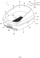
- FIG. 1 is a schematic perspective view of an animal litter box 1 according to the present embodiment.
- FIG. 2 is an exploded side view of the animal litter box 1.
- three directions that are orthogonal to (intersect) one another namely a "front-back direction", a “lateral direction”, and a “vertical direction” are defined as shown in FIG. 1 .
- the front-back direction is a direction extending along the longitudinal direction of the animal litter box 1, the side from which a tray 20 is pulled out from a lower container 30 is defined as the "front" side, and the opposite side is defined as the "back" side.
- the lateral direction is a direction extending along the width direction of the animal litter box 1, the right side when the animal litter box 1 is viewed from the front side is defined as "right”, and the opposite side (left side) is defined as "left”.
- the vertical direction is a direction extending along the up-down direction, the upper side in the up-down direction is defined as “up”, and the lower side in the up-down direction is defined as "down”.
- the animal litter box 1 includes an upper container 10, the lower container 30, the tray 20 which is accommodated in the lower container 30, and a cover 40.
- each of the upper container 10, the tray 20, the lower container 30, and the cover 40 is formed of polyolefin-based thermoplastic resin, such as polyethylene (PE), polypropylene (PP), polyethylene terephthalate (PET), or the like.
- the material for constituting the members is not limited thereto.
- other resins, metal plates such as stainless steel plates, aluminum plates and the like may be used.
- the upper container 10, the tray 20, the lower container 30, and the cover 40 can be freely attached to and detached from each other.
- the lower container 30 is placed being stacked below and attached to the upper container 10.
- the lower container 30 detachably accommodates the tray 20 in which an absorbent body 20a that absorbs excreted urine and the like can be placed.
- the cover 40 is attached to the upper portion of the upper container 10. Since the members can be detached from each other in this manner, this makes it easier to clean.
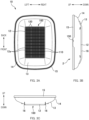
- FIG. 3A is a top view of the upper container 10.
- FIG. 3B is a right side view of the upper container 10.
- FIG. 3C is a front view of the upper container 10.
- the upper container 10 is a substantially box-shaped member having an open upper side, and an animal such as a cat performs excretion on the upper surface of the upper container 10.
- the upper container 10 of the present embodiment has a bottom portion 12, an outer peripheral portion 13, a side portion 14, and a folded-back portion 15.
- the bottom portion 12 is a portion that constitutes the bottom surface of the upper container 10, and is positioned at the lowest position in the upper container 10 in the vertical direction.
- a urine passage portion 100 (corresponding to a liquid passage portion) that allows urine or the like excreted by an animal to pass from above to below in the vertical direction.
- the urine passage portion 100 has a plurality of holes 12a (corresponding to openings) that penetrate in the vertical direction and allow urine to pass through downward, and the excreted urine passes through the holes 12a and moves from above to below in the upper container 10.
- the urine passage portion 100 has a plurality of cross ribs 110 (corresponding to the second ribs) extending along the lateral direction and arranged side-by-side in the front-back direction. Further, the urine passage portion 100 has a plurality of longitudinal ribs 120 (corresponding to the first ribs) extending along the front-back direction and arranged side-by-side in the lateral direction.
- the urine passage portion 100 is formed in a grid shape by the plurality of cross ribs 110 and the plurality of longitudinal ribs 120.
- the holes 12a are formed by its outer periphery being surrounded by the cross ribs 110 and the longitudinal ribs 120. It should be noted that the specific configuration example of the urine passage portion 100 (the cross ribs 110, the longitudinal ribs 120, and the holes 12a) will be described later.
- the outer peripheral portion 13 is provided continuing from the bottom portion 12, and in the present embodiment, the outer peripheral portion 13 is provided continuing so as to be inclined upward from the peripheral edge of the urine passage portion 100.
- a plate member 16 extending along the longitudinal rib 120 is provided on each of two lateral sides of the plurality of longitudinal ribs 120 (urine passage portion 100).
- the pair of plate members 16 protrude downward and has a function as legs when the upper container 10 is placed on the floor, for example.
- the side portion 14 is a surface that stands upward from the peripheral edge of the outer peripheral portion 13 and has a larger inclination than the outer peripheral portion 13.
- the folded-back portion 15 is a portion formed by folding back the upper end of the side portion 14 downward. As shown in FIGS. 2 and 3B , notches 150 are formed at positions of the folded-back portion 15 facing each other in the lateral direction.
- the notches 150 is portions which an owner and the like can put on with their fingers for attaching the upper container 10 to the lower container 30 or for detaching the upper container 10 from the lower container 30. It should be noted that only one notch 150 of the two notches 150 is shown in FIGS. 2 and 3B .
- FIG. 4 is a plan view of the tray 20.
- the tray 20 is a flat and box-shaped container with a shallow bottom in which the absorbent body 20a absorbing urine that has passed through the urine passage portion 100 of the upper container 10 is placed.
- the tray 20 has a bottom portion 21, side portions 22, an absorbent-body placement portion 23, and handle portions 24.
- the bottom portion 21 is a portion that forms the bottom surface of the tray 20, and as shown in FIG. 4 , the planar shape thereof is rectangular.
- the side portions 22 each are a wall-shaped portion formed in the end portion of the bottom portion 21 so as to surround the outer periphery of the tray 20.
- the absorbent-body placement portion 23 is a region in which the absorbent body 20a that absorbs urine or the like is placed on the bottom portion 21.
- the absorbent-body placement portion 23 is formed by being surrounded by the side portions 22.
- FIG. 4 shows a state where the absorbent body 20a (shown by the hatched portion in the drawing) is placed in the absorbent-body placement portion 23.
- the absorbent body 20a is a liquid-absorbent sheet member that absorbs urine excreted by an animal such as a cat, and is formed of a liquid-absorbent material such as pulp fibers or superabsorbent polymer.
- deodorant microcapsules and an antimicrobial agent may be provided in the absorbent body 20a in order to trap the odor of absorbed urine and prevent the propagation of various bacteria.
- the absorbent body 20a is shown as a rectangular sheet member, but the shape of the absorbent body 20a is not limited as long as it can be held in the absorbent-body placement portion 23.
- the handle portions 24 are portions formed in two front-back end portions of the tray 20. When inserting the tray 20 into the lower container 30 or pulling out the tray 20 from the lower container 30, the handle portion 24 is held and moved so that the tray 20 can slidingly move in the front-back direction. It should be noted that the tray 20 of the present embodiment has a symmetrical shape in the front-back direction, and this makes it possible to accommodate it in the lower container 30 with the front-back direction of the tray 20 reversed.
- the handle portion 24 is formed with a hooking hole 240 for hooking a hand when putting in or taking out (attaching and detaching) the tray 20 to or from an accommodation space 36 of the lower container 30.
- FIG. 5A is a top view of the lower container 30.
- FIG. 5B is a right side view of the lower container 30.
- FIG. 5C is a front view of the lower container 30.
- the lower container 30 is a substantially box-shaped member having an open upper portion, and is placed being stacked below and attached to the upper container 10 as shown in FIGS. 1 and 2 while the animal litter box 1 is in use. Then, the lower container 30 supports the upper container 10 from below.
- the lower container 30 includes a bottom portion 31, side wall portions 32, a front wall portion 33, a back wall portion 34, a folded-back portion 35, and an accommodation space 36.
- the bottom portion 31 is a portion that constitutes the bottom surface of the lower container 30.
- a bottom opening 31a that penetrates in the vertical direction is provided.
- the side wall portions 32 are portions that constitute the lateral side surfaces of the lower container 30, and are wall-shaped portions that stand upward from two lateral ends of the bottom portion 31.
- the front wall portion 33 is a portion that constitutes the front surface of the lower container 30 and is a wall-shaped portion that stands from the front end of the bottom portion 31.
- an attach/detach opening 33a for inserting or taking out (attaching and detaching) the tray 20 to or from the accommodation space 36.
- a recessed portion 33b that, at the time of holding the tray 20 with a hand, prevents the hand (fingers) from coming into contact with the front wall portion 33.
- the back wall portion 34 is a portion that constitutes the back surface of the lower container 30 and is a wall-shaped portion that stands from the back end of the bottom portion 31.
- the folded-back portion 35 is a portion formed by folding back downward the upper ends of the side wall portions 32, the front wall portion 33, and the back wall portion 34. At positions of the folded-back portion 35 opposite to each other in the lateral direction, fitting pieces 352 each having a protruding portion 352a are formed overhanging downward. It should be noted that, in FIGS. 2 and 5B , only one fitting piece 352 of the two fitting pieces 352 is shown. Further, on the upper end of the folded-back portion 35, two protrusions 351 that protrude upward are provided at positions opposite to each other in the lateral direction. The protrusions 351 are placed in a space formed by the folded-back portion 15 of the upper container 10 when the upper container 10 is attached to the lower container 30. Accordingly, the lateral movement of the upper container 10 with respect to the lower container 30 is restrained.
- the accommodation space 36 is a space for accommodating the tray 20 in the lower container 30. It should be noted that in FIGS. 2 and 5B , the accommodation space 36 is shown by a dashed line.
- the cover 40 includes a cover opening 41, side wall portions 42, a front wall portion 43, a back wall portion 44, and an overhanging portion 45.
- the cover opening 41 is a portion that serves as an entrance for an animal to the animal litter box 1. An animal can enter and leave the animal litter box 1 from the cover opening 41.
- the side wall portions 42 are wall-shaped portions respectively provided on two lateral sides of the cover opening 41.
- the front wall portion 43 is a wall-shaped portion provided on the front side of the cover opening 41
- the back wall portion 44 is a wall-shaped portion provided on the back side of the cover opening 41.
- the granules S and excrement are prevented from scattering, whereas in the front side, it is possible to ensure a wide visibility of the animal so as to easily confirm the outside situation from inside the litter box. By ensuring sufficient visibility even during excretion, the animal can use the animal litter box 1 at ease.
- the overhanging portion 45 is a portion overhanging downward from the lower ends of the side wall portions 42, the front wall portion 43, and the back wall portion 44.
- the side wall portions 42, the front wall portion 43, the back wall portion 44, and the overhanging portion 45 are integrally formed. Further, the cover 40 does not have a bottom surface and penetrates in the vertical direction.
- fitting pieces 450 each having a through hole 450a are formed overhanging downward. It should be noted that, in FIG. 2 , only one fitting piece 450 of the two fitting pieces 450 is shown.
- the through hole 450a is to be fitted with the protruding portion 352a of the lower container 3 when the cover 40 is attached to the lower container 30 to which the upper container 10 is mounted.
- the through hole 450a is formed in a shape of a cat face.
- FIG. 6 is a schematic cross-sectional view of the animal litter box 1 taken along the front-back direction. It should be noted that the cover 40 is not shown in FIG. 6 .
- the granules S such as cat litter are placed on the urine passage portion 100 as shown in FIG. 6 , and an animal such as a cat performs excretion on the granules S.
- the granules S exhibit effects of moisture removal and deodorization by absorbing an ammonia component upon coming into contact with urine or the like excreted by an animal. Further, by placing the granules S in the urine passage portion 100, it makes an animal more likely to recognize that the place (urine passage portion 100) is a location where excretion is intended.
- stone sand formed of zeolite is placed as the granules S. Details of the granules S (stone sand) will be described later.
- the animal When an animal such as a cat performs excretion, the animal enters the animal litter box 1 from the cover opening 41, and the animal excretes urine or the like to a portion of the urine passage portion 100 in which the granules S are placed on the upper surface of the upper container 10.
- the excreted urine passes through the plurality of holes 12a of the urine passage portion 100 and drops downward while being in contact with the granules S.
- the urine is absorbed by the absorbent body 20a arranged below the urine passage portion 100 and is stored in the tray 20.
- the urine passage portion 100 has the plurality of cross ribs 110 and the plurality of longitudinal ribs 120.
- the cross ribs 110 are provided extending along the lateral direction and connect the plurality of longitudinal ribs 120 arranged side-by-side in the lateral direction.
- the longitudinal ribs 120 are provided extending along the front-back direction and connect the plurality of cross ribs 110 arranged side-by-side in the front-back direction.
- FIG. 7A is an enlarged view of a part of the urine passage portion 100
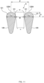
- FIG. 7B is a cross-sectional view taken along the line A-A in FIG. 7A . It should be noted that, for convenience, FIG. 7B shows a cross section in the case where a curved portion is not provided at the lower end of the longitudinal rib 120.
- the cross rib 110 positioned on the front side is referred to as a "front cross rib 110a”
- the cross rib 110 positioned on the back side is referred to as a "back cross rib 110b”.
- the longitudinal rib 120 positioned on the left side is referred to as a "left longitudinal rib 120a”
- the longitudinal rib 120 positioned on the right side is referred to as a "right longitudinal rib 120b”.
- the cross ribs 110 and the longitudinal ribs 120 are formed as a single unit, but this is not essential.
- the cross ribs 110 and the longitudinal ribs 120 may be shaped as separate components and joined.
- the distance L between two adjacent cross ribs 110 is longer than the distance between two adjacent longitudinal ribs 120 (the opening width W of the hole 12a) (L > W). Therefore, the hole 12a whose outer periphery is surrounded by the cross ribs 110a and 110b and the longitudinal ribs 120a and 120b has a slit shape that is elongated in the front-back direction. That is, in the present embodiment, the front-back direction corresponds to the longitudinal direction of the hole 12a, and the lateral direction corresponds to the width direction of the hole 12a.
- front curved surfaces 113a and 113b and back curved surfaces 114a and 114b that are curved toward the longitudinal rib 120.
- the front curved surface 113a that is curved toward the left longitudinal rib 120a and the front curved surface 113b that is curved toward the right longitudinal rib 120b are continuously formed. Therefore an arc surface is formed extending from the left longitudinal rib 120a to the right longitudinal rib 120b, on the front side of the cross rib 110. Similarly, on the back side of the cross rib 110, an arc surface is formed of the back curved surface 114a that is curved toward the left longitudinal rib 120a and the back curved surface 114b that is curved toward the right longitudinal rib 120b.
- the hole 12a whose outer periphery is surrounded by the front cross rib 110a, the back cross rib 110b, the left longitudinal rib 120a, and the right longitudinal rib 120b has a rounded shape formed of the front curved surfaces 113a and 113b and the back curved surfaces 114a and 114b. Accordingly, compared with the case where the cross ribs 110 are connected to the longitudinal ribs 120 at a right angle (the case where the holes 12a each have a rectangular shape), a connection portion where the cross rib 110 and the longitudinal rib 120 are connected becomes a smooth curved surface, and thus dirt such as urine is less likely to be accumulated in the connection portion.
- the hole 12a has a rectangular shape (the cross rib 110 and the longitudinal rib 120 are connected at a right angle)
- the urine is likely to accumulate at two corner locations.
- the end portions each have an arc shape as in the present embodiment, urine is likely to accumulate at one location. Therefore, since the amount of urine accumulated is decreased compared with the case of the rectangular shape, the animal litter box is more hygienic.
- the above-described opening width W is the width of a portion of the hole 12 that is not rounded (a portion having the largest lateral length), and corresponds to the maximum width of the hole 12a in the lateral direction (width direction).
- the front curved surfaces 113a and 113b and the back curved surfaces 114a and 114b does not have to be provided (the hole 12a does not have to be formed in a rectangular shape).
- a curved portion 112 that is curved upward in an arc shape is provided extending between two longitudinal ribs 120 that are adjacent to each other, and a part of the curved portion 112 serves as a lower inclined surface 112a.
- a lowermost part 110L of the cross rib 110 corresponds to the boundary with the longitudinal rib 120 in the lower inclined surface 112a.
- the vertical position of the lowermost part 110L is the same as the vertical position of a lowermost part 120L of the longitudinal rib 120.
- the lowermost part 120L of the longitudinal rib 120 is a portion of the longitudinal rib 120 that protrudes farthest downward.
- FIG. 7B shows a cross section in the case where a curved portion is not provided at the lower end of the longitudinal ribs 120.
- a curved portion that is curved upward may be provided at the lower end of the longitudinal ribs 120, extending between two cross ribs 110 that are adjacent to each other.
- urine or the like is made more likely to flow downward along the curved portion of the longitudinal rib 120, making it easier to flow down toward the lower container 30.
- providing the curved portion in at least either of the cross ribs 110 and the longitudinal ribs 120 it is possible to improve the drainage of urine compared with the case where the curved portion is not provided.
- the dimension D in the width direction (lateral direction) is the maximum dimension Da.
- the position of a portion where the longitudinal rib 120 has the maximum dimension Da (the position in the vertical direction) will also be referred to as a position T.
- the uppermost part 120H and two widthwise end portions located at the position T are connected by an upper curved surface 121 (corresponding to the curved surface).
- the upper curved surface 121 is a curved surface that is curved upward, and in the present embodiment, the upper side with respect to the position T of the longitudinal rib 120 has a semicircular shape. This makes urine or the like less likely to be accumulated on the upper part of the longitudinal rib 120 and more likely to flow downward. Further, as described later, the granule S can be easily removed when the granule S is caught in the hole 12a.
- a lower curved surface 122 that extends downward and is curved is provided below the position T, and the lower curved surface 122 and the lower inclined surface 112a of the cross rib 110 are continuous. Therefore, in the present embodiment, the curved portion 112 of the cross rib 110 and the lower curved surface 122 of the longitudinal rib 120 are smoothly continuous.
- the dimension D decreases toward the lower end. Accordingly, the urine or the like that has flowed down from above along the longitudinal rib 120, or that has flowed down along the curved portion 112 of the cross rib 110 are accumulated in the lowermost part 120L and become large droplets, and the urine is more likely to fall down with its own weight, thereby improving the drainage of urine. It should be noted that the dimension D does not necessarily have to decrease toward the lower end of the longitudinal rib 120. Further, the curved surface (upper curved surface 121) above the position T oes not necessarily have to exist. For example, the longitudinal ribs 120 may have a rectangular cross section.
- FIG. 8A is a schematic perspective view of the granule S.
- FIG. 8B is a schematic side view of the chipped granule S.
- the granule S of the present embodiment is stone sand formed of zeolite and is shaped into a cylindrical shape as shown in FIG. 8A .
- the particle diameter d of the granule S is 5.5 mm and the particle length l of the granule S is 10.0 mm.
- FIG. 8B shows a part of the granule S in the case of being chipped along the dashed line in FIG. 8A .
- the maximum length of the granule S in the particle length direction is defined as a length m ( m ⁇ l ), and the minimum length is defined as a length n ( n ⁇ m).
- the hole 12a of the urine passage portion 100 is formed having a size that does not allow the passage of the granule S.
- the hole 12a is provided having the opening width W of 2.7 mm, and the granule S (particle diameter d: 5.5 mm, particle length l : 10.0 mm) in FIG. 8A is not caught in the hole 12a.
- the granule S is chipped as shown in FIG. 8B , there is a risk that the chipped granule S is caught in the hole 12a (between the longitudinal ribs 120 that are adjacent to each other in the width direction).
- the granule S when the granule S is caught in the hole 12a, the granule cannot be easily removed, and there arise a hygiene problem and a problem that labour for preparing a special tool is needed. Therefore, in order to make the chipped granule S less likely to be caught even in the case where the granule S is chipped, the conditions of the holes 12a of the liquid passage portion 100 were examined. It should be noted that, here, as the granule S, a granule whose length m is smaller than the particle diameter d (specifically, a particle diameter less than 5.5 mm) was selected (that is, d > m > n ) .
- FIG. 9 is a diagram illustrating the relationship between the shape of the granule S and the number of times of clogging.
- the same test as the later-described particle clogging test was conducted several times, and the number of times of clogging of the clogged granule S (particles) and the length m and the length n of the granule were evaluated. It should be noted that the test was conducted under the condition that the opening width W of the hole 12a is 2.5 mm.
- the particle whose number of times of clogging is 5 is one that is particularly likely to clog.
- the average value of the length n was 1.98 mm
- the average value of the length m was 3.06 mm.
- the average value of m + n was 5.04 mm
- the average value of m - n was 1.08 mm.
- FIG. 10 is a diagram illustrating an example of a state where the granule S is caught in the hole 12a (between the longitudinal ribs 120).
- the length n of the granule S is smaller than the opening width W of the hole 12a (the space between the adjacent longitudinal ribs 120)
- the opening width W is smaller than ( m + n )/2
- the amount of particles entering the hole 12a is small and the particle is less likely to be caught.
- the opening width W is made excessively small, there is a risk that the liquid permeability (the liquid permeability in a state where a plurality of granules S are placed on the urine passage portion 100) is decreased and urine remains in the urine passage portion 100. Therefore, it is desirable that the opening width W is in a range in which the liquid permeability can be maintained at 90% or more. Specifically, it is desirable that the opening width W is 1.7 mm or more (see the liquid permeation test described later). This makes it possible to reduce the amount of urine remaining in the urine passage portion 100, making an offensive odor less likely to be generated. It should be noted that a method for calculating the liquid permeability and the like will be described later.
- the opening width W is larger than the maximum dimension Da of the longitudinal ribs 120.
- the maximum dimension Da of the longitudinal ribs 120 is 2.2 mm
- the opening width W is 2.5 mm or less, the granules S can be made less likely to be caught.
- the configuration is not limited thereto, and the opening width W may be equal to or smaller than the maximum dimension Da of the longitudinal ribs 120.
- a configuration is aacceptable in which 2.2 ⁇ W ⁇ 1.7.
- the uppermost part 120H of the longitudinal rib 120 and the end portions in the width direction (lateral direction) at the position T are connected by the upper curved surface 121. Accordingly, when the granule S is caught in the hole 12a, the granule S can be moved along the upper curved surface 121 of the longitudinal rib 120. Thus, the granule S is easily removed.
- FIG. 11 is a diagram illustrating a state where a granule S that is particularly likely to clog is clogged farthest deeply. It should be noted that, among the particularly easily cloggable particles (the particles whose the number of times of clogging is 5), the particle that is closest to the back of the hole 12a is the particle having the smallest difference (m - n) between the length m and the length n (in FIG. 9 , the particle having a length n of 2.12 mm and a length m of 2.62 mm). FIG. 11 shows a state where the particle (granule S) is clogged in the hole 12a.
- the particularly easily cloggable particles the particles whose the number of times of clogging is 5
- the particle that is closest to the back of the hole 12a is the particle having the smallest difference (m - n) between the length m and the length n (in FIG. 9 , the particle having a length n of 2.12 mm and a length m
- the particle (granule S) shown in FIG. 11 enters deeply between the longitudinal ribs 120.
- the vertical length of a portion of the granule S that protrudes upward beyond the position T of the longitudinal rib 120 was approximately one (1.1 mm) of the five equal divisions of the particle diameter d (5.5 mm) of the granule S.
- the length X in the longitudinal rib 120 (a difference between the uppermost part 120H and the position T) is larger than 1.1 mm, the granule cannot be removed when the granule is caught as shown in the drawing. Therefore, it is desirable that the length X of the longitudinal rib 120 is 1.1 mm or less.
- half of the maximum dimension Da of the longitudinal rib 120 (Da/2) is 1.1 mm or less (in other words, it is desirable that the maximum dimension Da is 2.2 mm or less).
- Da/2 is larger than 1.1 mm
- the granule S cannot be removed so as to climb over the longitudinal rib 120.
- Setting Da/2 to 1.1 mm or less makes it possible to remove the granule S so as to climb over the longitudinal rib 120.
- a widthwise center-to-center distance P of the longitudinal ribs 120 that are adjacent to each other in the width direction (lateral direction) is the opening width W + (2 ⁇ Da/2)
- W + Da is 4.7 (mm) or less
- the number of longitudinal ribs 120 per unit area increases. Therefore, the bottom portion 12 is less likely to be bent and the aperture is not formed, making the granule S less likely to be caught.
- a longitudinal center-to-center distance between the cross ribs 110 that are adjacent to each other in the longitudinal direction (front-back direction) is 5 to 50 mm.
- the center-to-center distance is 50 mm or more, there is a risk that the bottom portion 12 (urine passage portion 100) is bent due to applying the load of the animal, and there is a risk that the granule S is likely to be caught when the bottom portion returns from the bent state to the original state.
- the ratio P/X of the center-to-center distance P (here, W + Da) to the length X of the longitudinal rib 120 (here, Da/2) is 4.3 or less (more preferably, 4.1 or less).
- the height from the uppermost part 120H to the position H is small, and accordingly even if the granule S enters, the granule S easily leaves the hole 12a. This makes the granule S less likely to be caught. Accordingly, urine is not accumulated, and urine permeation is not hindered, making an offensive odor less likely to generate.
- the ratio W/X of the opening width W to the length X of the longitudinal rib 120 is 2.3 or less (more preferably 2.1 or less). This makes the granule S less likely to be caught. Accordingly, urine is not accumulated and urine permeation is not hindered, making an offensive odor less likely to generate.
- the ratio W/Da of the opening width W to the maximum dimension Da of the longitudinal ribs 120 is 1.2 or less (more preferably 1.1 or less). In this case, since the space between the longitudinal ribs 120 are narrow, it is possible to suppress the clogging of the granule S. Since the granule S is not clogged, urine is not accumulated, and urine permeation is not hindered, making an offensive odor less likely to generate.
- Tests (a particle clogging test and a permeability test) were conducted using a test duckboard, and a suitable range of the opening width W was evaluated.
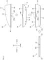
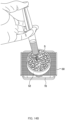
- FIGS. 12A to 12D are schematic explanatory diagrams illustrating a test method for a particle clogging test.
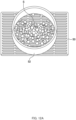
- a cylindrical member 52 is placed (fixed) in a test duckboard 50, and the granules S (here, stone sand having a particle length of 5 mm or less) is introduced into the cylindrical member 52.
- the granules S here, stone sand having a particle length of 5 mm or less
- test duckboard 50 and the like prepared in FIG. 12A are placed on a sieve shaker 60, and the lid (not shown) is closed, and shaking is performed at 60 Hz for 1 minute.
- test duckboard 50 is taken out from the sieve shaker 60 and inclined at approximately 90 degrees as shown in FIG. 12C .
- FIG. 13 is a diagram illustrating the test results of the particle clogging test. While the average number of clogged particles with an opening width W of 2.7 mm (conventional width) is 7.0 particles, the average number of clogged particles with an opening width W of 2.5 mm is 2.3 particles, which is less than half. That is, it was confirmed that, by setting the opening width W to 2.5 mm, the granules S could be made less likely to be clogged (less likely to be caught) compared with the case where the opening width W is 2.7 mm.
- the granules is introduced into the cylindrical member provided on the test duckboard, and sieved 20 times with hands. Subsequently, the test duckboard is inclined vertically (approximately 90 degrees), and then the number of particles clogged in the test duckboard is counted.
- the above-described test was conducted five times per test duckboard (opening width W) for each product (granule), and the average value of the clogged particles was calculated. Further, a numerical value obtained by multiplying the number of clogged particles (average value) by 40 was defined as a 2L conversion value, and evaluation was performed using the 2L conversion value.
- the opening width W was 2.5 mm
- the number of clogged particles was less than half compared with the case where the opening width W was 2.7 mm.
- the opening width W was 2.5 mm and no clogging occurred.
- the opening width W was 2.3 mm, no clogging occurred in either product.
- the opening width W is preferably 2.5 mm or less (more preferably 2.3 mm or less).
- FIGS. 14A to 14C are schematic explanatory diagrams illustrating a test method for a liquid permeation test.
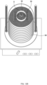
- the cylindrical member 52 is placed on the test duckboard 50, a level full of the granules S (stone sand) are put into the cylindrical member 52, and the cylindrical member is arranged on a receiving container 70 having an open upper part.
- 20 g of artificial urine is dropped from a height of 20 mm above the cylindrical member 52 by using a syringe or the like, over a period of approximately 10 seconds.
- the artificial urine is allowed to stand (stand still) for 15 seconds after dropping, and then the weight is measured with a weight scale 80 as shown in FIG. 14C .
- the weight scale 80 is set in advance to zero in a state where only the receiving container 70 is put on. Therefore, in the case of FIG. 14C , the weight of the artificial urine that has passed through the test duckboard 50 is 18.77 g.
- liquid permeability is calculated from the dropping amount (here, 20 g) and the measured weight by Equation (1).
- Liquid permeability % measured weight / dropping amount ⁇ 100
- the liquid permeability is 93.85% according to Equation (1).
- the calculated liquid permeability of 90% or more was defined as acceptable (OK), and the liquid permeability less than 90% was defined as unacceptable (NG).
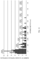
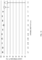
- FIG. 15 is a diagram illustrating the test results of the liquid permeation test.
- the horizontal axis represents the opening width W (mm)
- the longitudinal axis represents the liquid permeability (%). It should be noted that the liquid permeability test was conducted multiple times for each opening width W (test duckboard 50), and in FIG. 15 , the results are shown in the box-and-whisker plot (maximum value, minimum value, and quartile).
- a liquid permeability of 90% or more is maintained until the opening width W reaches 1.7 mm.
- a liquid permeability of 90% or more cannot be maintained (liquid permeability: NG). Therefore, it is desirable that the opening width W is 1.7 mm or more.
- the opening width W of the holes 12a is equal to or larger than 1.7 mm and equal to or less than 2.5 mm (more preferably equal to or less than 2.3 mm). Accordingly, while maintaining a liquid permeability of 90% or more, the granules S can be made less likely to be caught.
- all the longitudinal ribs 120 are formed having the same shape, but the configuration is not limited thereto. For example, there may be mixed ribs having different vertical lengths.
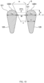
- FIGS. 16A and 16B are explanatory diagrams illustrating modified examples of the longitudinal ribs 120.
- the longitudinal ribs 120 and the longitudinal ribs 120' are alternately arranged. It should be noted that in FIG. 16A , the uppermost positions of the longitudinal ribs 120 and 120' are aligned, and, in FIG. 16B , the lowermost positions of the longitudinal ribs 120 and 120' are aligned.
- the longitudinal ribs 120 have the same shape as that of the above-described embodiment, and the vertical length (height) of the longitudinal ribs 120 is h 1 .
- the longitudinal ribs 120' have a vertical length h 2 ( ⁇ hi), and the vertical length is shorter than the vertical length of the longitudinal ribs 120. More specifically, in the longitudinal ribs 120', the length of a portion located below the portion of the maximum dimension Da is shorter than in the longitudinal ribs 120, and the longitudinal ribs 120' are formed in a shape whose cross section is close to a circle.
- the longitudinal ribs 120 have different vertical lengths, even in the case where the granule S is caught between the longitudinal ribs, the caught granule S can be easily removed.
- the longitudinal ribs 120 shapes having different vertical lengths
- the configuration is not limited thereto and three or more types of shapes may be used.
- the holes 12a of the urine passage portion 100 are each formed in a substantially rectangular shape (slit shape) that is elongated in the front-back direction, but the configuration is not limited thereto.
- the hole may have an elliptical shape.
- the long axis direction corresponds to the longitudinal direction
- the short axis direction corresponds to the width direction.
- the maximum width in the short axis direction (width direction) is 2.5 mm or less (preferably 2.3 mm or less) . This can make the granules S less likely to be caught.
- stone sand of zeolite is used as the granules S, but the present invention is not limited thereto.
- stone sand of bentonite may be used.
- silica gel, vegetable-derived sand, paper sand, and the like may be used.
- silica gel "Deo-Toilet Deodorizing Litter” (manufactured by Unicharm Corporation) may be used, and as vegetable derived sand, “Nyantomo Clean Toilet, Deodorizing and Antibacterial Chips” (manufactured by Kao Corporation), “Deo-Toilet Deodorising and Antibacterial Chips” (manufactured by Unicharm Corporation), and “Deo-Toilet Deodoring Litter containing green tea ingrediants and no scattering” (manufactured by Unicharm Corporation) may be used. These particles were subjected to the particle clogging test with a duckboard having an opening width of 2.5 mm, and as a result, not a single particle was clogged.
- the configuration and shape of the animal litter box is not limited to the above embodiment.
- the animal litter box 1 of the above embodiment includes four members, namely the upper container 10, the tray 20, the lower container 30, and the cover 40.
- the animal litter box 1 does not have to necessarily include these four members.
- the following aspect may be employed.
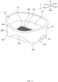
- FIG. 17 is a perspective view of an animal litter box 1'
- FIG. 18 is an exploded view of the animal litter box 1'.
- the animal litter box 1' includes an upper container 10' and a lower container 30'.
- the upper container 10' is a container having an open upper part and includes a bottom portion 12', an outer peripheral portion 13', and a side portion 14'.
- the bottom portion 12' is a portion that constitutes the bottom surface of the upper container 10'.
- the urine passage portion 100' is provided on the bottom portion 12'. Further, the urine passage portion 100' has a plurality of holes 12a' for allowing urine to pass through downward, formed therein.
- the configuration of the urine passage portion 100' is similar to the configuration of the urine passage portion 100 of the animal litter box 1 described above. However, in this example, the directions of the holes 12a' (longitudinal ribs and cross ribs) are different from those of the above embodiment, and the hole 12a' has a laterally-elongated shape. That is, in this example, the lateral direction corresponds to the longitudinal direction of the hole 12a', and the front-back direction corresponds to the width direction of the hole 12'.
- the outer peripheral portion 13' is a portion that surrounds the outside of the bottom portion 12', and forms an upward incline (inclined surface) extending outward from the bottom portion 12'.
- the side portion 14' is a wall surface that rises up from the peripheral edge of the outer peripheral portion 13' and constitutes the outer wall of the upper container 10'.
- the side portion 14 ' has an upper wall portion 14A and an extension wall portion 14B.
- the lower end of the upper wall portion 14A is continuous from the upper end of the outer peripheral portion 13'.
- the upper wall portion 14A extends to the upper end portion of the upper container 10', and is curved outward at the upper end portion.
- the extension wall portion 14B is a portion that is located on the outer surface side of the upper wall portion 14A and extends downward from the upper wall portion 14A. Further, the extension wall portion 14B is positioned outside the lower container 30'. In four corners of the upper container 10', the extension wall portion 14B extends downward and constitutes leg portion 14C. Further, as shown in FIGS. 17 and 18 , the extension wall portion 14B has a notch portion 14D that is notched in an upward arc-shaped manner between a leg portion 14C and another leg portion 14C.
- the lower container 30' is a container having an open upper part and includes a bottom portion 31', a side wall portion 32', and handle portions 37.
- the bottom portion 31' is a portion for receiving urine that has passed through the plurality of holes 12a' of the liquid passage portion 100' of the upper container 10', and the absorbent body 20a is arranged on the bottom portion 31'. That is, the bottom portion 31' of this example corresponds to the absorbent-body placement portion.
- the side wall portion 32' is a wall-shaped portion that rises up from the peripheral edge of the bottom portion 31'.
- the handle portions 37 are arranged on the outer surface of the side wall portion 32'.
- the handle portions 37 are provided one by one (two in total) on the lateral side of the lower container 30'.
- the handle portions 37 are provided so as to protrude outside the lower container 30'.
- the granules S are placed on the urine passage portion 100' of the upper container 10' in the same manner as in the above-described embodiment.
- the urine passage portion 100' (the hole 12a' or the like) is formed in the same manner as in the above-described embodiment, and this can make the granules S less likely to be caught.
Landscapes
- Life Sciences & Earth Sciences (AREA)
- Environmental Sciences (AREA)
- Animal Husbandry (AREA)
- Biodiversity & Conservation Biology (AREA)
- Zoology (AREA)
- Housing For Livestock And Birds (AREA)
- Acyclic And Carbocyclic Compounds In Medicinal Compositions (AREA)
- Toys (AREA)
- Medicines Containing Material From Animals Or Micro-Organisms (AREA)
Abstract
Description
- The present invention relates to an animal litter box.
- Animal litter boxes for use by animals who are kept indoors such as cats are conventionally known. For example,
Patent Literature 1 discloses an animal litter box including: a liquid passage portion (urine passage portion) having a plurality of openings (slits) through which urine excreted by an animal passes; and an absorbent-body placement portion for arranging an absorbent body which absorbs urine that has passed through the liquid passage portion. Further, when such an animal litter box is used, granules such as stone sand (e.g., cat litter) are placed on the liquid passage portion. Therefore, the openings of the liquid passage portion are formed having a size that allows passage of urine but prevents passage of granules. - Patent Literature 1:
Japanese Patent Application Publication No. 2016-158565 - However, there is a risk that the granules (e.g., stone sand) are chipped and the chipped granules are caught (clogged) in the openings. When the granules are caught in the openings, the granules cannot be easily removed, and there arise a hygiene problem and a problem that labour for preparing a special tool is needed.
- The present invention was achieved in light of problems that described above and an aspect of the present invention is to provide an animal litter box which is capable of making granules less likely to be caught.
- A main aspect of the present invention for achieving the above-described aspect is an animal litter box having a vertical direction including: a liquid passage portion having a plurality of openings through which urine pass downward; and an absorbent-body placement portion in which an absorbent body for absorbing the urine that has passed through the liquid passage portion is placed, a plurality of granules being placed on the liquid passage portion, each of the openings having a longitudinal direction, and a width direction that is orthogonal to the longitudinal direction, a maximum width of the openings in the width direction is equal to or smaller than 2.5 mm.
- Features of the present invention other than the above will become clear by reading the description of the present specification with reference to the accompanying drawings.
- According to the present invention, it is possible to provide an animal litter box which is capable of making granules less likely to be caught.
-
-
FIG. 1 is a schematic perspective view of ananimal litter box 1 according to the present embodiment. -
FIG. 2 is an exploded side view of theanimal litter box 1. -
FIG. 3A is a top view of anupper container 10. -
FIG. 3B is a right side view of theupper container 10. -
FIG. 3C is a front view of theupper container 10. -
FIG. 4 is a plan view of thetray 20. -
FIG. 5A is a top view of alower container 30. -
FIG. 5B is a right side view of thelower container 30. -
FIG. 5C is a front view of thelower container 30. -
FIG. 6 is a schematic cross-sectional view of theanimal litter box 1 taken along the front-back direction. -
FIG. 7A is an enlarged view of a part of aurine passage portion 100. -
FIG. 7B is a cross-sectional view taken along the line A-A inFIG. 7A . -
FIG. 8A is a schematic perspective view of a granule S, andFIG. 8B is a schematic side view of a chipped granule S. -
FIG. 9 is a diagram illustrating the relationship between the shape of the granule S and the number of times of clogging. -
FIG. 10 is a diagram illustrating a state where the granule S is caught in ahole 12a (between longitudinal ribs 120). -
FIG. 11 is a diagram illustrating a state where a granule S that is particularly likely to clog is clogged farthest deeply. -
FIG. 12A is a schematic explanatory diagram illustrating a test method for a particle clogging test. -
FIG. 12B is a schematic explanatory diagram illustrating the test method of the particle clogging test. -
FIG. 12C is a schematic explanatory diagram illustrating the test method of the particle clogging test. -
FIG. 12D is a schematic explanatory diagram illustrating the test method of the particle clogging test. -
FIG. 13 is a diagram illustrating the test results of the particle clogging test. -
FIG. 14A is a schematic explanatory diagram illustrating a test method for a liquid permeation test. -
FIG. 14B is a schematic explanatory diagram illustrating the test method for the liquid permeation test. -
FIG. 14C is a schematic explanatory diagram illustrating the test method for the liquid permeation test. -
FIG. 15 is a diagram illustrating the test results of the liquid permeation test. -
FIGS. 16A and 16B are explanatory diagrams illustrating modified examples of thelongitudinal ribs 120. -
FIG. 17 is a perspective view of an animal litter box 1'. -
FIG. 18 is an exploded view of the animal litter box 1'. - At least following matters will become clear with description of this specification and attached drawings.
- An animal litter box having a vertical direction including: a liquid passage portion having a plurality of openings through which urine pass downward; and an absorbent-body placement portion in which an absorbent body for absorbing the urine that has passed through the liquid passage portion is placed, a plurality of granules being placed on the liquid passage portion, each of the openings having a longitudinal direction, and a width direction that is orthogonal to the longitudinal direction, a maximum width of the openings in the width direction is equal to or smaller than 2.5 mm.
- According to the above-described animal litter box, by setting the width of the openings of the liquid passage portion to be equal to or smaller than 2.5 mm, the number of granules (stone sand) caught in the openings is less than half of the case of the conventional width (2.7 mm) (see the particle clogging test described later). Therefore, the granules can be made less likely to be caught in the openings.
- In such an animal litter box, it is desirable that the maximum width of the openings is equal to or smaller than 2.3 mm.
- According to the above-described animal litter box, the granules can be made further less likely to be caught.
- In such an animal litter box, it is desirable that a liquid permeability in a state where the plurality of granules are placed on the liquid passage portion is equal to or greater than 90%.
- According to the above-described animal litter box, it is possible to reduce the amount of urine remaining in the liquid passage portion, making an offensive odor less likely to generate.
- In such an animal litter box, it is desirable that the maximum width of the openings is equal to or larger than 1.7 mm.
- According to the above-described animal litter box, while maintaining the liquid permeability, the granules can be made less likely to be caught.
- In such an animal litter box, it is desirable that the liquid passage portion has a plurality of first ribs extending in the longitudinal direction and arranged side-by-side in the width direction, that each of the openings is formed between the first ribs that are adjacent to each other in the width direction, and that the maximum width of the openings is larger than a maximum dimension of the first ribs in the width direction.
- According to the above-described animal litter box, the granules can be made less likely to be caught.
- In such an animal litter box, it is desirable that the liquid passage portion has a plurality of first ribs extending along the longitudinal direction and arranged side-by-side in the width direction, and that a maximum dimension of the first ribs in the width direction is equal to or smaller than 2.2 mm.
- According to the above-described animal litter box, when the granule is caught in the opening, the granule can be removed so as to climb over the first rib.
- In such an animal litter box, it is desirable that at a predetermined position in the vertical direction between an uppermost part of the first rib and a lowermost part of the first rib, a dimension of the first ribs in the width direction is the maximum dimension, and that the uppermost part of the first rib and a widthwise end portion of the first rib that is located at the predetermined position are connected by a curved surface.
- According to the above-described animal litter box, when the granule is caught in the opening, the granule can be moved along the curved surface of the first rib. Thus, the granule is easily removed.
- In such an animal litter box, it is desirable that a difference between a position of the uppermost part of the first rib and the predetermined position in the vertical direction is equal to or smaller than 1.1 mm.
- According to the above-described animal litter box, when the granule is caught in the opening, the granule is easily removed.
- In such an animal litter box, it is desirable that a widthwise central space between the first ribs that are adjacent to each other in the width direction is equal to or smaller than 4.7 mm.
- According to the above-described animal litter box, when the granule is caught in the opening, the granule can be removed so as to climb over the first rib.
- In such an animal litter box, it is desirable that the plurality of first ribs include a rib having a first vertical length, and a rib having a second vertical length that is different from the first vertical length.
- According to the above-described animal litter box, the first ribs include ribs having different lengths (heights), and therefore even in the case where the granule is caught in the opening, the caught granule can be easily removed.
- In such an animal litter box, it is desirable that the liquid passage portion has a plurality of second ribs extending in the width direction and arranged side-by-side in the longitudinal direction, that an outer periphery of each of the openings is surrounded by the first rib and the second rib, and that in at least either of the first ribs and the second ribs, a lower end has a curved portion that is curved upward.
- According to the above-described animal litter box, urine is make likely to flow downward along the curved portion, improving the drainage of urine is.
- The animal litter box according to the present embodiment is used by animals who are kept indoors such as cats, for example. The "animals" in the present specification include not only commonly known pets such as cats, dogs, rabbits, hamsters, and the like but also young offspring of a tigers or lions and the like.
-
FIG. 1 is a schematic perspective view of ananimal litter box 1 according to the present embodiment.FIG. 2 is an exploded side view of theanimal litter box 1. In addition, in the description below, three directions that are orthogonal to (intersect) one another, namely a "front-back direction", a "lateral direction", and a "vertical direction" are defined as shown inFIG. 1 . The front-back direction is a direction extending along the longitudinal direction of theanimal litter box 1, the side from which atray 20 is pulled out from alower container 30 is defined as the "front" side, and the opposite side is defined as the "back" side. The lateral direction is a direction extending along the width direction of theanimal litter box 1, the right side when theanimal litter box 1 is viewed from the front side is defined as "right", and the opposite side (left side) is defined as "left". The vertical direction is a direction extending along the up-down direction, the upper side in the up-down direction is defined as "up", and the lower side in the up-down direction is defined as "down". - The
animal litter box 1 includes anupper container 10, thelower container 30, thetray 20 which is accommodated in thelower container 30, and acover 40. It should be noted that each of theupper container 10, thetray 20, thelower container 30, and thecover 40 is formed of polyolefin-based thermoplastic resin, such as polyethylene (PE), polypropylene (PP), polyethylene terephthalate (PET), or the like. However, the material for constituting the members is not limited thereto. For example, other resins, metal plates such as stainless steel plates, aluminum plates and the like may be used. - As shown in
FIG. 2 , theupper container 10, thetray 20, thelower container 30, and thecover 40 can be freely attached to and detached from each other. Specifically, thelower container 30 is placed being stacked below and attached to theupper container 10. Thelower container 30 detachably accommodates thetray 20 in which anabsorbent body 20a that absorbs excreted urine and the like can be placed. Thecover 40 is attached to the upper portion of theupper container 10. Since the members can be detached from each other in this manner, this makes it easier to clean. -
FIG. 3A is a top view of theupper container 10.FIG. 3B is a right side view of theupper container 10.FIG. 3C is a front view of theupper container 10. Theupper container 10 is a substantially box-shaped member having an open upper side, and an animal such as a cat performs excretion on the upper surface of theupper container 10. Theupper container 10 of the present embodiment has abottom portion 12, an outerperipheral portion 13, aside portion 14, and a folded-back portion 15. - The
bottom portion 12 is a portion that constitutes the bottom surface of theupper container 10, and is positioned at the lowest position in theupper container 10 in the vertical direction. On thebottom portion 12, there is provided a urine passage portion 100 (corresponding to a liquid passage portion) that allows urine or the like excreted by an animal to pass from above to below in the vertical direction. Theurine passage portion 100 has a plurality ofholes 12a (corresponding to openings) that penetrate in the vertical direction and allow urine to pass through downward, and the excreted urine passes through theholes 12a and moves from above to below in theupper container 10. - As shown in
FIG. 3A , theurine passage portion 100 has a plurality of cross ribs 110 (corresponding to the second ribs) extending along the lateral direction and arranged side-by-side in the front-back direction. Further, theurine passage portion 100 has a plurality of longitudinal ribs 120 (corresponding to the first ribs) extending along the front-back direction and arranged side-by-side in the lateral direction. Theurine passage portion 100 is formed in a grid shape by the plurality ofcross ribs 110 and the plurality oflongitudinal ribs 120. Theholes 12a are formed by its outer periphery being surrounded by thecross ribs 110 and thelongitudinal ribs 120. It should be noted that the specific configuration example of the urine passage portion 100 (thecross ribs 110, thelongitudinal ribs 120, and theholes 12a) will be described later. - The outer
peripheral portion 13 is provided continuing from thebottom portion 12, and in the present embodiment, the outerperipheral portion 13 is provided continuing so as to be inclined upward from the peripheral edge of theurine passage portion 100. As shown inFIGS. 3B and 3C , on the back side of the outerperipheral portion 13, aplate member 16 extending along thelongitudinal rib 120 is provided on each of two lateral sides of the plurality of longitudinal ribs 120 (urine passage portion 100). As shown inFIG. 3C , the pair ofplate members 16 protrude downward and has a function as legs when theupper container 10 is placed on the floor, for example. - The
side portion 14 is a surface that stands upward from the peripheral edge of the outerperipheral portion 13 and has a larger inclination than the outerperipheral portion 13. - The folded-
back portion 15 is a portion formed by folding back the upper end of theside portion 14 downward. As shown inFIGS. 2 and3B ,notches 150 are formed at positions of the folded-back portion 15 facing each other in the lateral direction. Thenotches 150 is portions which an owner and the like can put on with their fingers for attaching theupper container 10 to thelower container 30 or for detaching theupper container 10 from thelower container 30. It should be noted that only onenotch 150 of the twonotches 150 is shown inFIGS. 2 and3B . -
FIG. 4 is a plan view of thetray 20. Thetray 20 is a flat and box-shaped container with a shallow bottom in which theabsorbent body 20a absorbing urine that has passed through theurine passage portion 100 of theupper container 10 is placed. Thetray 20 has abottom portion 21,side portions 22, an absorbent-body placement portion 23, and handleportions 24. - The
bottom portion 21 is a portion that forms the bottom surface of thetray 20, and as shown inFIG. 4 , the planar shape thereof is rectangular. - The
side portions 22 each are a wall-shaped portion formed in the end portion of thebottom portion 21 so as to surround the outer periphery of thetray 20. - The absorbent-
body placement portion 23 is a region in which theabsorbent body 20a that absorbs urine or the like is placed on thebottom portion 21. The absorbent-body placement portion 23 is formed by being surrounded by theside portions 22.FIG. 4 shows a state where theabsorbent body 20a (shown by the hatched portion in the drawing) is placed in the absorbent-body placement portion 23. Theabsorbent body 20a is a liquid-absorbent sheet member that absorbs urine excreted by an animal such as a cat, and is formed of a liquid-absorbent material such as pulp fibers or superabsorbent polymer. Further, deodorant microcapsules and an antimicrobial agent may be provided in theabsorbent body 20a in order to trap the odor of absorbed urine and prevent the propagation of various bacteria. It should be noted that inFIG. 4 , theabsorbent body 20a is shown as a rectangular sheet member, but the shape of theabsorbent body 20a is not limited as long as it can be held in the absorbent-body placement portion 23. - The
handle portions 24 are portions formed in two front-back end portions of thetray 20. When inserting thetray 20 into thelower container 30 or pulling out thetray 20 from thelower container 30, thehandle portion 24 is held and moved so that thetray 20 can slidingly move in the front-back direction. It should be noted that thetray 20 of the present embodiment has a symmetrical shape in the front-back direction, and this makes it possible to accommodate it in thelower container 30 with the front-back direction of thetray 20 reversed. Thehandle portion 24 is formed with a hookinghole 240 for hooking a hand when putting in or taking out (attaching and detaching) thetray 20 to or from anaccommodation space 36 of thelower container 30. -
FIG. 5A is a top view of thelower container 30.FIG. 5B is a right side view of thelower container 30.FIG. 5C is a front view of thelower container 30. - The
lower container 30 is a substantially box-shaped member having an open upper portion, and is placed being stacked below and attached to theupper container 10 as shown inFIGS. 1 and2 while theanimal litter box 1 is in use. Then, thelower container 30 supports theupper container 10 from below. - The
lower container 30 includes abottom portion 31,side wall portions 32, afront wall portion 33, aback wall portion 34, a folded-back portion 35, and anaccommodation space 36. - The
bottom portion 31 is a portion that constitutes the bottom surface of thelower container 30. In thebottom portion 31 of the present embodiment, as shown inFIG. 5A , abottom opening 31a that penetrates in the vertical direction is provided. - The
side wall portions 32 are portions that constitute the lateral side surfaces of thelower container 30, and are wall-shaped portions that stand upward from two lateral ends of thebottom portion 31. - The
front wall portion 33 is a portion that constitutes the front surface of thelower container 30 and is a wall-shaped portion that stands from the front end of thebottom portion 31. In thefront wall portion 33, there is provided an attach/detachopening 33a for inserting or taking out (attaching and detaching) thetray 20 to or from theaccommodation space 36. Further, as shown inFIGS. 1 and5C , in thefront wall portion 33, there is formed a recessedportion 33b that, at the time of holding thetray 20 with a hand, prevents the hand (fingers) from coming into contact with thefront wall portion 33. - The
back wall portion 34 is a portion that constitutes the back surface of thelower container 30 and is a wall-shaped portion that stands from the back end of thebottom portion 31. - The folded-
back portion 35 is a portion formed by folding back downward the upper ends of theside wall portions 32, thefront wall portion 33, and theback wall portion 34. At positions of the folded-back portion 35 opposite to each other in the lateral direction,fitting pieces 352 each having a protrudingportion 352a are formed overhanging downward. It should be noted that, inFIGS. 2 and5B , only onefitting piece 352 of the twofitting pieces 352 is shown. Further, on the upper end of the folded-back portion 35, twoprotrusions 351 that protrude upward are provided at positions opposite to each other in the lateral direction. Theprotrusions 351 are placed in a space formed by the folded-back portion 15 of theupper container 10 when theupper container 10 is attached to thelower container 30. Accordingly, the lateral movement of theupper container 10 with respect to thelower container 30 is restrained. - The
accommodation space 36 is a space for accommodating thetray 20 in thelower container 30. It should be noted that inFIGS. 2 and5B , theaccommodation space 36 is shown by a dashed line. - As shown in
FIGS. 1 and2 , thecover 40 includes acover opening 41,side wall portions 42, afront wall portion 43, aback wall portion 44, and an overhangingportion 45. - The
cover opening 41 is a portion that serves as an entrance for an animal to theanimal litter box 1. An animal can enter and leave theanimal litter box 1 from thecover opening 41. - The
side wall portions 42 are wall-shaped portions respectively provided on two lateral sides of thecover opening 41. - The
front wall portion 43 is a wall-shaped portion provided on the front side of thecover opening 41, and theback wall portion 44 is a wall-shaped portion provided on the back side of thecover opening 41. By providing such wall portions (theside wall portions 42, thefront wall portion 43, and the back wall portion 44), the granules S (seeFIG. 6 ) and excrement are prevented from spilling or scattering outside the animal litter box 1 (upper container 10). Further, in the present embodiment, as shown inFIGS. 1 and2 , theside wall portions 42 are formed such that the height of the side wall portions becomes lower as it goes forward. Accordingly, in the back side, the granules S and excrement are prevented from scattering, whereas in the front side, it is possible to ensure a wide visibility of the animal so as to easily confirm the outside situation from inside the litter box. By ensuring sufficient visibility even during excretion, the animal can use theanimal litter box 1 at ease. - The overhanging
portion 45 is a portion overhanging downward from the lower ends of theside wall portions 42, thefront wall portion 43, and theback wall portion 44. In the present embodiment, theside wall portions 42, thefront wall portion 43, theback wall portion 44, and the overhangingportion 45 are integrally formed. Further, thecover 40 does not have a bottom surface and penetrates in the vertical direction. - As shown in
FIG. 2 , in the overhangingportion 45, at positions opposite to each other in the lateral direction,fitting pieces 450 each having a throughhole 450a are formed overhanging downward. It should be noted that, inFIG. 2 , only onefitting piece 450 of the twofitting pieces 450 is shown. The throughhole 450a is to be fitted with the protrudingportion 352a of thelower container 3 when thecover 40 is attached to thelower container 30 to which theupper container 10 is mounted. In the present embodiment, the throughhole 450a is formed in a shape of a cat face. -
FIG. 6 is a schematic cross-sectional view of theanimal litter box 1 taken along the front-back direction. It should be noted that thecover 40 is not shown inFIG. 6 . - When the
animal litter box 1 is to be used, the granules S such as cat litter are placed on theurine passage portion 100 as shown inFIG. 6 , and an animal such as a cat performs excretion on the granules S. The granules S exhibit effects of moisture removal and deodorization by absorbing an ammonia component upon coming into contact with urine or the like excreted by an animal. Further, by placing the granules S in theurine passage portion 100, it makes an animal more likely to recognize that the place (urine passage portion 100) is a location where excretion is intended. It should be noted that, in the present embodiment, stone sand formed of zeolite is placed as the granules S. Details of the granules S (stone sand) will be described later. - When an animal such as a cat performs excretion, the animal enters the
animal litter box 1 from thecover opening 41, and the animal excretes urine or the like to a portion of theurine passage portion 100 in which the granules S are placed on the upper surface of theupper container 10. The excreted urine passes through the plurality ofholes 12a of theurine passage portion 100 and drops downward while being in contact with the granules S. The urine is absorbed by theabsorbent body 20a arranged below theurine passage portion 100 and is stored in thetray 20. - As described above, the
urine passage portion 100 has the plurality ofcross ribs 110 and the plurality oflongitudinal ribs 120. Thecross ribs 110 are provided extending along the lateral direction and connect the plurality oflongitudinal ribs 120 arranged side-by-side in the lateral direction. Further, thelongitudinal ribs 120 are provided extending along the front-back direction and connect the plurality ofcross ribs 110 arranged side-by-side in the front-back direction. -
FIG. 7A is an enlarged view of a part of theurine passage portion 100, andFIG. 7B is a cross-sectional view taken along the line A-A inFIG. 7A . It should be noted that, for convenience,FIG. 7B shows a cross section in the case where a curved portion is not provided at the lower end of thelongitudinal rib 120. - In the following description, among the two
cross ribs 110 that are adjacent to each other, thecross rib 110 positioned on the front side is referred to as a "front cross rib 110a", and thecross rib 110 positioned on the back side is referred to as a "back cross rib 110b". Further, among the twolongitudinal ribs 120 that are adjacent to each other, thelongitudinal rib 120 positioned on the left side is referred to as a "leftlongitudinal rib 120a", and thelongitudinal rib 120 positioned on the right side is referred to as a "rightlongitudinal rib 120b". Further, in the present embodiment, thecross ribs 110 and thelongitudinal ribs 120 are formed as a single unit, but this is not essential. Thecross ribs 110 and thelongitudinal ribs 120 may be shaped as separate components and joined. - As shown in
FIG. 7A , in the present embodiment, the distance L between two adjacent cross ribs 110 (thefront cross ribs 110a and theback cross ribs 110b) is longer than the distance between two adjacent longitudinal ribs 120 (the opening width W of thehole 12a) (L > W). Therefore, thehole 12a whose outer periphery is surrounded by thecross ribs longitudinal ribs hole 12a, and the lateral direction corresponds to the width direction of thehole 12a. - Further, as shown in
FIG. 7A , in the portion of thecross rib 110 that is connected to thelongitudinal rib 120, there are provided frontcurved surfaces curved surfaces longitudinal rib 120. - In the present embodiment, as shown in
FIG. 7A , the frontcurved surface 113a that is curved toward the leftlongitudinal rib 120a and the frontcurved surface 113b that is curved toward the rightlongitudinal rib 120b are continuously formed. Therefore an arc surface is formed extending from the leftlongitudinal rib 120a to the rightlongitudinal rib 120b, on the front side of thecross rib 110. Similarly, on the back side of thecross rib 110, an arc surface is formed of the backcurved surface 114a that is curved toward the leftlongitudinal rib 120a and the backcurved surface 114b that is curved toward the rightlongitudinal rib 120b. - Therefore, the
hole 12a whose outer periphery is surrounded by thefront cross rib 110a, theback cross rib 110b, the leftlongitudinal rib 120a, and the rightlongitudinal rib 120b has a rounded shape formed of the frontcurved surfaces curved surfaces cross ribs 110 are connected to thelongitudinal ribs 120 at a right angle (the case where theholes 12a each have a rectangular shape), a connection portion where thecross rib 110 and thelongitudinal rib 120 are connected becomes a smooth curved surface, and thus dirt such as urine is less likely to be accumulated in the connection portion. Specifically, in the case where thehole 12a has a rectangular shape (thecross rib 110 and thelongitudinal rib 120 are connected at a right angle), when urine remains at any end portion (any side) of thehole 12a, the urine is likely to accumulate at two corner locations. In contrast, when the end portions each have an arc shape as in the present embodiment, urine is likely to accumulate at one location. Therefore, since the amount of urine accumulated is decreased compared with the case of the rectangular shape, the animal litter box is more hygienic. - The above-described opening width W is the width of a portion of the
hole 12 that is not rounded (a portion having the largest lateral length), and corresponds to the maximum width of thehole 12a in the lateral direction (width direction). - It should be noted that the front
curved surfaces curved surfaces hole 12a does not have to be formed in a rectangular shape). - As shown in
FIG. 7B , in thecross rib 110, on the lower side of the portion of thecross rib 110 that is connected to thelongitudinal rib 120, there is provided a lowerinclined surface 112a that is inclined obliquely upward from thelongitudinal rib 120. Accordingly, dirt such as urine is less likely to be accumulated in the boundary portion between thecross rib 110 and thelongitudinal rib 120, and this makes brushing or the like easier, facilitating cleaning. - Further, at the lower end of the
cross rib 110, acurved portion 112 that is curved upward in an arc shape is provided extending between twolongitudinal ribs 120 that are adjacent to each other, and a part of thecurved portion 112 serves as a lowerinclined surface 112a. Providing thecurved portion 112 makes urine or the like that has flowed down along thecross rib 110 from above is not accumulated on the lower part of thecross rib 110, becoming more likely to flow downward along thecurved portion 112. This makes urine or the like easier to flow down toward the lower container 30 (the drainage of urine is improved). - In
FIG. 7B , alowermost part 110L of thecross rib 110 corresponds to the boundary with thelongitudinal rib 120 in the lowerinclined surface 112a. In the present embodiment, the vertical position of thelowermost part 110L is the same as the vertical position of alowermost part 120L of thelongitudinal rib 120. Here, thelowermost part 120L of thelongitudinal rib 120 is a portion of thelongitudinal rib 120 that protrudes farthest downward. - It should be noted that, as described above,
FIG. 7B shows a cross section in the case where a curved portion is not provided at the lower end of thelongitudinal ribs 120. However, a curved portion that is curved upward may be provided at the lower end of thelongitudinal ribs 120, extending between twocross ribs 110 that are adjacent to each other. Also in this case, urine or the like is made more likely to flow downward along the curved portion of thelongitudinal rib 120, making it easier to flow down toward thelower container 30. As described above, providing the curved portion in at least either of thecross ribs 110 and thelongitudinal ribs 120, it is possible to improve the drainage of urine compared with the case where the curved portion is not provided. - In the
longitudinal ribs 120, at a predetermined position in the vertical direction between theuppermost part 120H and thelowermost part 120L (e.g., the lower surface of the bottom portion 12), the dimension D in the width direction (lateral direction) is the maximum dimension Da. In the following description, the position of a portion where thelongitudinal rib 120 has the maximum dimension Da (the position in the vertical direction) will also be referred to as a position T. - Further, in the
longitudinal rib 120, theuppermost part 120H and two widthwise end portions located at the position T are connected by an upper curved surface 121 (corresponding to the curved surface). The uppercurved surface 121 is a curved surface that is curved upward, and in the present embodiment, the upper side with respect to the position T of thelongitudinal rib 120 has a semicircular shape. This makes urine or the like less likely to be accumulated on the upper part of thelongitudinal rib 120 and more likely to flow downward. Further, as described later, the granule S can be easily removed when the granule S is caught in thehole 12a. - Further, as shown in
FIG. 7B , in thelongitudinal rib 120, a lowercurved surface 122 that extends downward and is curved is provided below the position T, and the lowercurved surface 122 and the lowerinclined surface 112a of thecross rib 110 are continuous. Therefore, in the present embodiment, thecurved portion 112 of thecross rib 110 and the lowercurved surface 122 of thelongitudinal rib 120 are smoothly continuous. - By providing the lower
curved surface 122 also in the lower side of thelongitudinal rib 120, urine or the like that has flowed down along thelongitudinal rib 120 from the upper side is not accumulated on the lower part of thelongitudinal rib 120, and directly flows down toward thelower container 30. Furthermore, since the lowercurved surface 122 of thelongitudinal rib 120 and thecurved portion 112 of thecross rib 110 are smoothly continuous, it is possible to suppress the accumulation of dirt such as urine at the boundary portion between thecross rib 110 and thelongitudinal rib 120. - Further, below the position T of the
longitudinal rib 120, the dimension D decreases toward the lower end. Accordingly, the urine or the like that has flowed down from above along thelongitudinal rib 120, or that has flowed down along thecurved portion 112 of thecross rib 110 are accumulated in thelowermost part 120L and become large droplets, and the urine is more likely to fall down with its own weight, thereby improving the drainage of urine. It should be noted that the dimension D does not necessarily have to decrease toward the lower end of thelongitudinal rib 120. Further, the curved surface (upper curved surface 121) above the position T oes not necessarily have to exist. For example, thelongitudinal ribs 120 may have a rectangular cross section. - Relationship Between Granules S and
urine Passage Portion 100 -
FIG. 8A is a schematic perspective view of the granule S.FIG. 8B is a schematic side view of the chipped granule S. The granule S of the present embodiment is stone sand formed of zeolite and is shaped into a cylindrical shape as shown inFIG. 8A . In the state inFIG. 8A (non-chipped state), the particle diameter d of the granule S is 5.5 mm and the particle length l of the granule S is 10.0 mm. - However, such a granule S (stone sand) is chipped in some cases, for example, when the product is distributed or when the granule is stirred or stepped on by an animal (such as a cat).
FIG. 8B shows a part of the granule S in the case of being chipped along the dashed line inFIG. 8A . InFIG. 8B , the maximum length of the granule S in the particle length direction is defined as a length m (m < l), and the minimum length is defined as a length n (n < m). - As described above, the
hole 12a of theurine passage portion 100 is formed having a size that does not allow the passage of the granule S. Specifically, thehole 12a is provided having the opening width W of 2.7 mm, and the granule S (particle diameter d: 5.5 mm, particle length l: 10.0 mm) inFIG. 8A is not caught in thehole 12a. However, in the case where the granule S is chipped as shown inFIG. 8B , there is a risk that the chipped granule S is caught in thehole 12a (between thelongitudinal ribs 120 that are adjacent to each other in the width direction). Further, when the granule S is caught in thehole 12a, the granule cannot be easily removed, and there arise a hygiene problem and a problem that labour for preparing a special tool is needed. Therefore, in order to make the chipped granule S less likely to be caught even in the case where the granule S is chipped, the conditions of theholes 12a of theliquid passage portion 100 were examined. It should be noted that, here, as the granule S, a granule whose length m is smaller than the particle diameter d (specifically, a particle diameter less than 5.5 mm) was selected (that is, d > m > n). -
FIG. 9 is a diagram illustrating the relationship between the shape of the granule S and the number of times of clogging. Here, the same test as the later-described particle clogging test was conducted several times, and the number of times of clogging of the clogged granule S (particles) and the length m and the length n of the granule were evaluated. It should be noted that the test was conducted under the condition that the opening width W of thehole 12a is 2.5 mm. - In
FIG. 9 , the particle whose number of times of clogging is 5 is one that is particularly likely to clog. For the particles that are particularly likely to clog (particles whose number of times of clogging is 5), the average value of the length n was 1.98 mm, and the average value of the length m was 3.06 mm. The average value of m + n was 5.04 mm, and the average value of m - n was 1.08 mm. -
FIG. 10 is a diagram illustrating an example of a state where the granule S is caught in thehole 12a (between the longitudinal ribs 120). As shown in the drawing, in the case where the length n of the granule S is smaller than the opening width W of thehole 12a (the space between the adjacent longitudinal ribs 120), there is a risk that the granule S enters thehole 12. However, as shown inFIG. 10 , in the case where the opening width W is smaller than (m + n)/2, the amount of particles entering thehole 12a is small and the particle is less likely to be caught. - As described above, since the average value of m + n of the particularly-likely-to-clog particle is 5.04 mm, it is desirable that the opening width W is less than 5.04/2 = 2.52 (mm). Also in the later-described particle clogging test, it was confirmed that setting the opening width W to 2.5 mm or less makes it possible to reduce the clogging compared with the conventional width (2.7 mm).
- However, if the opening width W is made excessively small, there is a risk that the liquid permeability (the liquid permeability in a state where a plurality of granules S are placed on the urine passage portion 100) is decreased and urine remains in the
urine passage portion 100. Therefore, it is desirable that the opening width W is in a range in which the liquid permeability can be maintained at 90% or more. Specifically, it is desirable that the opening width W is 1.7 mm or more (see the liquid permeation test described later). This makes it possible to reduce the amount of urine remaining in theurine passage portion 100, making an offensive odor less likely to be generated. It should be noted that a method for calculating the liquid permeability and the like will be described later. - It should be noted that, in a range that satisfies the above-described dimensions, it is desirable that the opening width W is larger than the maximum dimension Da of the
longitudinal ribs 120. For example, in the case where the maximum dimension Da of thelongitudinal ribs 120 is 2.2 mm, it is desirable that 2.2 < the opening width W ≤ 2.5 is satisfied. Also in this case, since the opening width W is 2.5 mm or less, the granules S can be made less likely to be caught. However, the configuration is not limited thereto, and the opening width W may be equal to or smaller than the maximum dimension Da of thelongitudinal ribs 120. For example, in the case where the maximum dimension Da of thelongitudinal ribs 120 is 2.2 mm, a configuration is aacceptable in which 2.2 ≥ W ≥ 1.7. - In addition, in the present embodiment, the
uppermost part 120H of thelongitudinal rib 120 and the end portions in the width direction (lateral direction) at the position T are connected by the uppercurved surface 121. Accordingly, when the granule S is caught in thehole 12a, the granule S can be moved along the uppercurved surface 121 of thelongitudinal rib 120. Thus, the granule S is easily removed. -
FIG. 11 is a diagram illustrating a state where a granule S that is particularly likely to clog is clogged farthest deeply. It should be noted that, among the particularly easily cloggable particles (the particles whose the number of times of clogging is 5), the particle that is closest to the back of thehole 12a is the particle having the smallest difference (m - n) between the length m and the length n (inFIG. 9 , the particle having a length n of 2.12 mm and a length m of 2.62 mm).FIG. 11 shows a state where the particle (granule S) is clogged in thehole 12a. - The particle (granule S) shown in
FIG. 11 enters deeply between thelongitudinal ribs 120. In this state, the vertical length of a portion of the granule S that protrudes upward beyond the position T of thelongitudinal rib 120 was approximately one (1.1 mm) of the five equal divisions of the particle diameter d (5.5 mm) of the granule S. In the case where the length X in the longitudinal rib 120 (a difference between theuppermost part 120H and the position T) is larger than 1.1 mm, the granule cannot be removed when the granule is caught as shown in the drawing. Therefore, it is desirable that the length X of thelongitudinal rib 120 is 1.1 mm or less. - Further, it is desirable that half of the maximum dimension Da of the longitudinal rib 120 (Da/2) is 1.1 mm or less (in other words, it is desirable that the maximum dimension Da is 2.2 mm or less). In the case where Da/2 is larger than 1.1 mm, when the granule S is caught as shown in
FIG. 11 , the granule S cannot be removed so as to climb over thelongitudinal rib 120. Setting Da/2 to 1.1 mm or less (maximum dimension Da is 2.2 mm or less) makes it possible to remove the granule S so as to climb over thelongitudinal rib 120. - Further, since a widthwise center-to-center distance P of the
longitudinal ribs 120 that are adjacent to each other in the width direction (lateral direction) (a distance between theuppermost parts 120H) is the opening width W + (2 × Da/2), it is desirable that the distance P is 2.5 + 2.2 = 4.7 (mm) or less. Accordingly, the granule S can be removed so as to climb over thelongitudinal rib 120. Further, when W + Da is 4.7 (mm) or less, the number oflongitudinal ribs 120 per unit area increases. Therefore, thebottom portion 12 is less likely to be bent and the aperture is not formed, making the granule S less likely to be caught. It should be noted that, it is desirable that a longitudinal center-to-center distance between thecross ribs 110 that are adjacent to each other in the longitudinal direction (front-back direction) is 5 to 50 mm. In the case where the center-to-center distance is 50 mm or more, there is a risk that the bottom portion 12 (urine passage portion 100) is bent due to applying the load of the animal, and there is a risk that the granule S is likely to be caught when the bottom portion returns from the bent state to the original state. - Further, it is desirable that the ratio P/X of the center-to-center distance P (here, W + Da) to the length X of the longitudinal rib 120 (here, Da/2) is 4.3 or less (more preferably, 4.1 or less). In this case, the height from the
uppermost part 120H to the position H is small, and accordingly even if the granule S enters, the granule S easily leaves thehole 12a. This makes the granule S less likely to be caught. Accordingly, urine is not accumulated, and urine permeation is not hindered, making an offensive odor less likely to generate. - Further, it is desirable that the ratio W/X of the opening width W to the length X of the
longitudinal rib 120 is 2.3 or less (more preferably 2.1 or less). This makes the granule S less likely to be caught. Accordingly, urine is not accumulated and urine permeation is not hindered, making an offensive odor less likely to generate. - Further, it is desirable that the ratio W/Da of the opening width W to the maximum dimension Da of the
longitudinal ribs 120 is 1.2 or less (more preferably 1.1 or less). In this case, since the space between thelongitudinal ribs 120 are narrow, it is possible to suppress the clogging of the granule S. Since the granule S is not clogged, urine is not accumulated, and urine permeation is not hindered, making an offensive odor less likely to generate. - Tests (a particle clogging test and a permeability test) were conducted using a test duckboard, and a suitable range of the opening width W was evaluated.
-
- * Test duckboard: Same pattern as that of urine passage portion 100 (manufactured with a 3D printer)
Opening width W (mm): 2.7, 2.5, 2.45, 2.4, 2.35, 2.3, 2.0, 1.9, 1.8 - * Cylindrical member:
inner diameter 100 mm,height 30 mm - * Granule: Test stone sand of zeolite (fine particles with a particle length of 5 mm or less)
-
- Sieve shaker Model: AS-200 manufactured by Retsch GmbH Speed: 3600 times/min (60 Hz)
- Amplitude: 1.80 mm
- Time: 1 min
-
FIGS. 12A to 12D are schematic explanatory diagrams illustrating a test method for a particle clogging test. - First, as shown in
FIG. 12A , acylindrical member 52 is placed (fixed) in atest duckboard 50, and the granules S (here, stone sand having a particle length of 5 mm or less) is introduced into thecylindrical member 52. - Next, as shown in
FIG. 12B , thetest duckboard 50 and the like prepared inFIG. 12A are placed on asieve shaker 60, and the lid (not shown) is closed, and shaking is performed at 60 Hz for 1 minute. - After the shaking is completed, the
test duckboard 50 is taken out from thesieve shaker 60 and inclined at approximately 90 degrees as shown inFIG. 12C . - Then, as shown in
FIG. 12D , the number of the granules S (stone sand) clogged in thetest duckboard 50 is counted. - The above-described test was conducted 10 times for each test duckboard 50 (opening width W), and the numbers (average values) of clogged particles were compared.
-
FIG. 13 is a diagram illustrating the test results of the particle clogging test. While the average number of clogged particles with an opening width W of 2.7 mm (conventional width) is 7.0 particles, the average number of clogged particles with an opening width W of 2.5 mm is 2.3 particles, which is less than half. That is, it was confirmed that, by setting the opening width W to 2.5 mm, the granules S could be made less likely to be clogged (less likely to be caught) compared with the case where the opening width W is 2.7 mm. - Further, it was confirmed that, when the opening width W was 2.3 mm or less, the average number of clogged particles was 0.1 particles or less and almost no clogging occurred.
- Using stone sand products for system toilets, which are commercially available products of two companies (Unicharm Corporation and Iris Ohyama Inc.) and are mainly made of zeolite, a particle clogging test was conducted in the product state (state not selected by particle length).
-
- * Test duckboard: Same as in the particle clogging test Opening width W (mm): 2.7, 2.5, 2.3
- * Cylindrical member: inner diameter 84 mm,
height 30 mm - * Granule: stone sand manufactured by Unicharm Co., Ltd. and stone sand manufactured by Iris Ohyama Inc.
- Taking out 50 ml of the granules (stone sand) from the packaged products for each company, the granules is introduced into the cylindrical member provided on the test duckboard, and sieved 20 times with hands. Subsequently, the test duckboard is inclined vertically (approximately 90 degrees), and then the number of particles clogged in the test duckboard is counted. The above-described test was conducted five times per test duckboard (opening width W) for each product (granule), and the average value of the clogged particles was calculated. Further, a numerical value obtained by multiplying the number of clogged particles (average value) by 40 was defined as a 2L conversion value, and evaluation was performed using the 2L conversion value.
- The test results are shown in Table 1.
[Table 1] Opening width W (mm) Number of clogged particles (in terms of 2L) Unicharm Iris Ohyama 2.7 40 32 2.5 0 16 2.3 0 0 - As shown in Table 1, in the case where the opening width W was 2.5 mm, the number of clogged particles was less than half compared with the case where the opening width W was 2.7 mm. Particularly, in the case of stone sand manufactured by Unicharm Corporation, the opening width W was 2.5 mm and no clogging occurred. Further, when the opening width W was 2.3 mm, no clogging occurred in either product.
- As described above, in the test using the commercially available products of stone sand made of zeolite, it was confirmed that, by setting the opening width W to 2.5 mm or less, the granules (stone sand) can be made less likely to be clogged (less likely to be caught) . Therefore, it can be said that the opening width W is preferably 2.5 mm or less (more preferably 2.3 mm or less).
-
- * Test duckboard: Same pattern as that of urine passage portion 100 (manufactured with a 3D printer)
Opening width W (mm): 2.7, 2.5, 2.45, 2.4, 2.35, 2.3, 2.0, 1.9, 1.8, 1.7, 1.6, 1.5 - * Cylindrical member: inner diameter 84 mm,
height 30 mm - * Granule: stone sand made of zeolite
- * Artificial urine: physiological saline
-
FIGS. 14A to 14C are schematic explanatory diagrams illustrating a test method for a liquid permeation test. - First, as shown in
FIG. 14A , thecylindrical member 52 is placed on thetest duckboard 50, a level full of the granules S (stone sand) are put into thecylindrical member 52, and the cylindrical member is arranged on a receivingcontainer 70 having an open upper part. - Next, as shown in
FIG. 14B , 20 g of artificial urine is dropped from a height of 20 mm above thecylindrical member 52 by using a syringe or the like, over a period of approximately 10 seconds. - The artificial urine is allowed to stand (stand still) for 15 seconds after dropping, and then the weight is measured with a
weight scale 80 as shown inFIG. 14C . It should be noted that theweight scale 80 is set in advance to zero in a state where only the receivingcontainer 70 is put on. Therefore, in the case ofFIG. 14C , the weight of the artificial urine that has passed through thetest duckboard 50 is 18.77 g. - Then, the liquid permeability is calculated from the dropping amount (here, 20 g) and the measured weight by Equation (1).

- For example, in the case where the measured weight is 18.77 g (
FIG. 14C ), the liquid permeability is 93.85% according to Equation (1). The calculated liquid permeability of 90% or more was defined as acceptable (OK), and the liquid permeability less than 90% was defined as unacceptable (NG). -
FIG. 15 is a diagram illustrating the test results of the liquid permeation test. InFIG. 15 , the horizontal axis represents the opening width W (mm), and the longitudinal axis represents the liquid permeability (%). It should be noted that the liquid permeability test was conducted multiple times for each opening width W (test duckboard 50), and inFIG. 15 , the results are shown in the box-and-whisker plot (maximum value, minimum value, and quartile). - In
FIG. 15 , a liquid permeability of 90% or more is maintained until the opening width W reaches 1.7 mm. However, when the opening width W is 1.6 mm or less, a liquid permeability of 90% or more cannot be maintained (liquid permeability: NG). Therefore, it is desirable that the opening width W is 1.7 mm or more. - Based on the above results (the results of the particle clogging test and the liquid permeation test), it is desirable that the opening width W of the
holes 12a is equal to or larger than 1.7 mm and equal to or less than 2.5 mm (more preferably equal to or less than 2.3 mm). Accordingly, while maintaining a liquid permeability of 90% or more, the granules S can be made less likely to be caught. - Although the above embodiments of the present invention have been described, but the above-described embodiments are intended to facilitate the understanding of the present invention and are not intended to limit the interpretation of the present invention. In addition, the present invention can be modified or improved within the scope of the gist of the present invention, and it is needless to say that equivalents thereof are included in the present invention. For example, modifications which will be described below are possible.
- In the above-described embodiment, all the longitudinal ribs 120 (the left
longitudinal ribs 120a and the rightlongitudinal ribs 120b) are formed having the same shape, but the configuration is not limited thereto. For example, there may be mixed ribs having different vertical lengths. -
FIGS. 16A and 16B are explanatory diagrams illustrating modified examples of thelongitudinal ribs 120. In this modified example, thelongitudinal ribs 120 and the longitudinal ribs 120' are alternately arranged. It should be noted that inFIG. 16A , the uppermost positions of thelongitudinal ribs 120 and 120' are aligned, and, inFIG. 16B , the lowermost positions of thelongitudinal ribs 120 and 120' are aligned. - The
longitudinal ribs 120 have the same shape as that of the above-described embodiment, and the vertical length (height) of thelongitudinal ribs 120 is h1. - The longitudinal ribs 120' have a vertical length h2 ( < hi), and the vertical length is shorter than the vertical length of the
longitudinal ribs 120. More specifically, in the longitudinal ribs 120', the length of a portion located below the portion of the maximum dimension Da is shorter than in thelongitudinal ribs 120, and the longitudinal ribs 120' are formed in a shape whose cross section is close to a circle. - Accordingly, by arranging the
longitudinal ribs 120 having different vertical lengths, even in the case where the granule S is caught between the longitudinal ribs, the caught granule S can be easily removed. It should be noted that in this example, the longitudinal ribs 120 (shapes having different vertical lengths) have two types of shapes. However, the configuration is not limited thereto and three or more types of shapes may be used. - Further, in the above embodiment, the
holes 12a of theurine passage portion 100 are each formed in a substantially rectangular shape (slit shape) that is elongated in the front-back direction, but the configuration is not limited thereto. For example, the hole may have an elliptical shape. It should be noted that, in a case of elliptical shape, the long axis direction corresponds to the longitudinal direction, and the short axis direction corresponds to the width direction. Also in this case, it is sufficient that the maximum width in the short axis direction (width direction) is 2.5 mm or less (preferably 2.3 mm or less) . This can make the granules S less likely to be caught. - Further, in the above embodiment, stone sand of zeolite is used as the granules S, but the present invention is not limited thereto. For example, stone sand of bentonite may be used. Alternatively, silica gel, vegetable-derived sand, paper sand, and the like may be used. For example, as silica gel, "Deo-Toilet Deodorizing Litter" (manufactured by Unicharm Corporation) may be used, and as vegetable derived sand, "Nyantomo Clean Toilet, Deodorizing and Antibacterial Chips" (manufactured by Kao Corporation), "Deo-Toilet Deodorising and Antibacterial Chips" (manufactured by Unicharm Corporation), and "Deo-Toilet Deodoring Litter containing green tea ingrediants and no scattering" (manufactured by Unicharm Corporation) may be used. These particles were subjected to the particle clogging test with a duckboard having an opening width of 2.5 mm, and as a result, not a single particle was clogged.
- Further, the configuration and shape of the animal litter box is not limited to the above embodiment. For example, the
animal litter box 1 of the above embodiment includes four members, namely theupper container 10, thetray 20, thelower container 30, and thecover 40. However, theanimal litter box 1 does not have to necessarily include these four members. For example, the following aspect may be employed. -
FIG. 17 is a perspective view of an animal litter box 1', andFIG. 18 is an exploded view of the animal litter box 1'. As shown in the drawing, the animal litter box 1' includes an upper container 10' and a lower container 30'. - The upper container 10' is a container having an open upper part and includes a bottom portion 12', an outer peripheral portion 13', and a side portion 14'.
- The bottom portion 12' is a portion that constitutes the bottom surface of the upper container 10'. The urine passage portion 100' is provided on the bottom portion 12'. Further, the urine passage portion 100' has a plurality of
holes 12a' for allowing urine to pass through downward, formed therein. The configuration of the urine passage portion 100' is similar to the configuration of theurine passage portion 100 of theanimal litter box 1 described above. However, in this example, the directions of theholes 12a' (longitudinal ribs and cross ribs) are different from those of the above embodiment, and thehole 12a' has a laterally-elongated shape. That is, in this example, the lateral direction corresponds to the longitudinal direction of thehole 12a', and the front-back direction corresponds to the width direction of the hole 12'. - The outer peripheral portion 13' is a portion that surrounds the outside of the bottom portion 12', and forms an upward incline (inclined surface) extending outward from the bottom portion 12'.
- The side portion 14' is a wall surface that rises up from the peripheral edge of the outer peripheral portion 13' and constitutes the outer wall of the upper container 10'. The side portion 14 ' has an
upper wall portion 14A and anextension wall portion 14B. - The lower end of the
upper wall portion 14A is continuous from the upper end of the outer peripheral portion 13'. Theupper wall portion 14A extends to the upper end portion of the upper container 10', and is curved outward at the upper end portion. - As shown in
FIGS. 17 and18 , theextension wall portion 14B is a portion that is located on the outer surface side of theupper wall portion 14A and extends downward from theupper wall portion 14A. Further, theextension wall portion 14B is positioned outside the lower container 30'. In four corners of the upper container 10', theextension wall portion 14B extends downward and constitutesleg portion 14C. Further, as shown inFIGS. 17 and18 , theextension wall portion 14B has anotch portion 14D that is notched in an upward arc-shaped manner between aleg portion 14C and anotherleg portion 14C. - As shown in
FIG. 18 , the lower container 30' is a container having an open upper part and includes a bottom portion 31', a side wall portion 32', and handleportions 37. - The bottom portion 31' is a portion for receiving urine that has passed through the plurality of
holes 12a' of the liquid passage portion 100' of the upper container 10', and theabsorbent body 20a is arranged on the bottom portion 31'. That is, the bottom portion 31' of this example corresponds to the absorbent-body placement portion. - The side wall portion 32' is a wall-shaped portion that rises up from the peripheral edge of the bottom portion 31'.
- The
handle portions 37 are arranged on the outer surface of the side wall portion 32'. Thehandle portions 37 are provided one by one (two in total) on the lateral side of the lower container 30'. Thehandle portions 37 are provided so as to protrude outside the lower container 30'. - It should be noted that, although not shown in the drawing, the granules S are placed on the urine passage portion 100' of the upper container 10' in the same manner as in the above-described embodiment. In this animal litter box 1', the urine passage portion 100' (the
hole 12a' or the like) is formed in the same manner as in the above-described embodiment, and this can make the granules S less likely to be caught. -
- 1, 1': animal litter box,
- 10, 10': upper container, 12, 12': bottom portion,
- 12a, 12a': hole (opening),
- 13, 13': outer peripheral portion, 14, 14': side portion,
- 14A: upper part wall portion, 14B: extension wall portion,
- 14C: leg portion,
- 14D: notch portion, 15: folded-back portion,
- 20: tray, 20a: absorbent body, 21: bottom portion, 22: side portion,
- 23: absorbent-body placement portion, 24: handle portion,
- 30, 30': lower container, 31: bottom portion, 31': bottom portion (absorbent-body placement portion)
- 31a: bottom opening,
- 32, 32': side wall portion, 33: front wall portion,
- 33b: recessed portion, 34: back wall portion,
- 35: folded-back portion,
- 36: accommodation space, 37: handle portion,
- 40: cover, 41: cover opening, 42: side wall portion,
- 43: front wall portion, 44: back wall portion, 45: overhanging portion,
- 50: test duckboard, 52: cylindrical member,
- 60: sieve shaker, 70: receiving container,
- 80: weight scale,
- 100: urine passage portion (liquid passage portion),
- 110: cross rib (second rib),
- 110a: front cross rib, 110b: back cross rib,
- 112: curved portion, 112a: lower inclined surface,
- 113a, 113b: front curved surface,
- 114a, 114b: back curved surface,
- 120: longitudinal rib (first rib),
- 120a: left longitudinal rib, 120b: right longitudinal rib,
- 120H: uppermost part, 120L: lowermost part,
- 121, upper curved surface (curved surface), 122: lower curved surface,
- 240: hooking hole,
- 351: protrusion, 352: fitting piece, 352a: protruding portion,
- S: granule,
- W: opening width (maximum width),
- D: dimension, Da: maximum dimension
Claims (11)
- An animal litter box having a vertical direction comprising:a liquid passage portion having a plurality of openings through which urine pass downward; andan absorbent-body placement portion in which an absorbent body for absorbing the urine that has passed through the liquid passage portion is placed,a plurality of granules being placed on the liquid passage portion,each of the openings havinga longitudinal direction, anda width direction that is orthogonal to the longitudinal direction,a maximum width of the openings in the width direction is equal to or smaller than 2.5 mm.
- The animal litter box according to claim 1, wherein
the maximum width of the openings is equal to or smaller than 2.3 mm. - The animal litter box according to claim 1 or 2, wherein
a liquid permeability in a state where the plurality of granules are placed on the liquid passage portion is equal to or greater than 90%. - The animal litter box according to any one of claims 1 to 3, wherein
the maximum width of the openings is equal to or larger than 1.7 mm. - The animal litter box according to any one of claims 1 to 4, whereinthe liquid passage portion has a plurality of first ribs extending in the longitudinal direction and arranged side-by-side in the width direction,each of the openings is formed between the first ribs that are adjacent to each other in the width direction, andthe maximum width of the openings is larger than a maximum dimension of the first ribs in the width direction.
- The animal litter box according to any one of claims 1 to 4, whereinthe liquid passage portion has a plurality of first ribs extending along the longitudinal direction and arranged side-by-side in the width direction, anda maximum dimension of the first ribs in the width direction is equal to or smaller than 2.2 mm.
- The animal litter box according to claim 5 or 6, whereinat a predetermined position in the vertical direction between an uppermost part of the first rib and a lowermost part of the first rib,
a dimension of the first ribs in the width direction is the maximum dimension, andthe uppermost part of the first rib and a widthwise end portion of the first rib that is located at the predetermined position are connected by a curved surface. - The animal litter box according to claim 7, wherein
a difference between a position of the uppermost part of the first rib and the predetermined position in the vertical direction is equal to or smaller than 1.1 mm. - The animal litter box according to any one of claims 5 to 8, wherein
a widthwise central space between the first ribs that are adjacent to each other in the width direction is equal to or smaller than 4.7 mm. - The animal litter box according to any one of claims 5 to 9, wherein
the plurality of first ribs includea rib having a first vertical length, anda rib having a second vertical length that is different from the first vertical length. - The animal litter box according to any one of claims 5 to 10, whereinthe liquid passage portion has a plurality of second ribs extending in the width direction and arranged side-by-side in the longitudinal direction,an outer periphery of each of the openings is surrounded by the first rib and the second rib, andin at least either of the first ribs and the second ribs, a lower end has a curved portion that is curved upward.
Applications Claiming Priority (2)
| Application Number | Priority Date | Filing Date | Title |
|---|---|---|---|
| JP2020176071A JP2022067386A (en) | 2020-10-20 | 2020-10-20 | Animal toilet |
| PCT/JP2021/037727 WO2022085518A1 (en) | 2020-10-20 | 2021-10-12 | Animal toilet |
Publications (2)
| Publication Number | Publication Date |
|---|---|
| EP4212013A1 true EP4212013A1 (en) | 2023-07-19 |
| EP4212013A4 EP4212013A4 (en) | 2024-03-06 |
Family
ID=81290401
Family Applications (1)
| Application Number | Title | Priority Date | Filing Date |
|---|---|---|---|
| EP21882659.2A Pending EP4212013A4 (en) | 2020-10-20 | 2021-10-12 | Animal toilet |
Country Status (7)
| Country | Link |
|---|---|
| US (1) | US12414536B2 (en) |
| EP (1) | EP4212013A4 (en) |
| JP (2) | JP2022067386A (en) |
| KR (1) | KR20230085152A (en) |
| CN (1) | CN116322316A (en) |
| AU (1) | AU2021366750A1 (en) |
| WO (1) | WO2022085518A1 (en) |
Families Citing this family (7)
| Publication number | Priority date | Publication date | Assignee | Title |
|---|---|---|---|---|
| JP2024013336A (en) | 2022-07-20 | 2024-02-01 | ユニ・チャーム株式会社 | pet system toilet |
| KR102849656B1 (en) * | 2023-06-13 | 2025-08-21 | 김성훈 | Cat toilet that can be reused repeatedly without replacement sand by automatically processing excrement |
| JP2025079420A (en) * | 2023-11-10 | 2025-05-22 | ユニ・チャーム株式会社 | System toilet for pets |
| USD1063257S1 (en) * | 2024-05-10 | 2025-02-18 | Peng Zhang | Cat litter box |
| USD1047312S1 (en) * | 2024-06-05 | 2024-10-15 | Zhuwu Li | Cat litter box |
| USD1053476S1 (en) * | 2024-06-13 | 2024-12-03 | Yingjia Chen | Cat litter box |
| USD1056365S1 (en) * | 2024-06-19 | 2024-12-31 | Zeqiao Shen | Cat litter box |
Family Cites Families (20)
| Publication number | Priority date | Publication date | Assignee | Title |
|---|---|---|---|---|
| NL7905924A (en) * | 1979-08-01 | 1980-09-30 | Wavin Bv | Floor element for an animal stall - is of polyethylene or polypropylene with coupling details and surface contour preventing slipping |
| US4362128A (en) * | 1981-06-26 | 1982-12-07 | B. L. Downey Company, Inc. | Livestock flooring |
| JP3939272B2 (en) * | 2003-06-20 | 2007-07-04 | ユニ・チャームペットケア株式会社 | Animal toilet |
| EP1790219B1 (en) * | 2004-09-02 | 2016-11-23 | Kao Corporation | Toilet for pet |
| JP2007074996A (en) * | 2005-09-14 | 2007-03-29 | Soen:Kk | Toilet for small animal and toilet for cat |
| NZ542641A (en) * | 2005-09-27 | 2008-06-30 | Fmfs Holdings Ltd | Toileting device for a domestic animal |
| KR200431205Y1 (en) * | 2006-08-19 | 2006-11-23 | 오상봉 | Money floor panels |
| JP5695849B2 (en) * | 2010-06-25 | 2015-04-08 | ユニ・チャーム株式会社 | System toilet for dogs |
| JP2012175910A (en) * | 2011-02-25 | 2012-09-13 | Iris Ohyama Inc | Pet toilet, treatment material recovering member used in the same and method for using pet toilet |
| JP5943564B2 (en) * | 2011-07-13 | 2016-07-05 | ユニ・チャーム株式会社 | Veterinary toilet |
| JP3196671U (en) * | 2015-01-15 | 2015-03-26 | アイリスオーヤマ株式会社 | Pet toilet and treatment material recovery member used therefor |
| JP6387312B2 (en) * | 2015-03-02 | 2018-09-05 | ユニ・チャーム株式会社 | Animal toilet |
| JP5768199B1 (en) * | 2015-03-02 | 2015-08-26 | ユニ・チャーム株式会社 | Animal toilet |
| JP5768200B1 (en) * | 2015-03-02 | 2015-08-26 | ユニ・チャーム株式会社 | Animal toilet |
| JP6482982B2 (en) * | 2015-07-31 | 2019-03-13 | ユニ・チャーム株式会社 | Animal toilet |
| CN207252470U (en) * | 2017-06-28 | 2018-04-20 | 北京美卡宠物用品有限公司 | Slidably basin in the cat lavatory of adjustment aperture |
| JP6295365B1 (en) * | 2017-11-10 | 2018-03-14 | ユニ・チャーム株式会社 | Animal toilet |
| US11000007B2 (en) * | 2018-06-08 | 2021-05-11 | Radio Systems Corporation | Pet litter box |
| JP6854539B2 (en) * | 2018-08-03 | 2021-04-07 | 第一衛材株式会社 | Animal toilet |
| JP7449674B2 (en) * | 2019-11-13 | 2024-03-14 | 株式会社大貴 | animal toilet |
-
2020
- 2020-10-20 JP JP2020176071A patent/JP2022067386A/en active Pending
-
2021
- 2021-10-12 WO PCT/JP2021/037727 patent/WO2022085518A1/en not_active Ceased
- 2021-10-12 AU AU2021366750A patent/AU2021366750A1/en active Pending
- 2021-10-12 KR KR1020237013182A patent/KR20230085152A/en active Pending
- 2021-10-12 EP EP21882659.2A patent/EP4212013A4/en active Pending
- 2021-10-12 CN CN202180069120.5A patent/CN116322316A/en active Pending
-
2023
- 2023-04-19 US US18/136,524 patent/US12414536B2/en active Active
-
2025
- 2025-02-18 JP JP2025024182A patent/JP2025081485A/en active Pending
Also Published As
| Publication number | Publication date |
|---|---|
| JP2022067386A (en) | 2022-05-06 |
| KR20230085152A (en) | 2023-06-13 |
| US12414536B2 (en) | 2025-09-16 |
| US20230255175A1 (en) | 2023-08-17 |
| WO2022085518A1 (en) | 2022-04-28 |
| JP2025081485A (en) | 2025-05-27 |
| CN116322316A (en) | 2023-06-23 |
| EP4212013A4 (en) | 2024-03-06 |
| AU2021366750A1 (en) | 2023-06-01 |
Similar Documents
| Publication | Publication Date | Title |
|---|---|---|
| US12414536B2 (en) | Animal litter box | |
| EP1790219B1 (en) | Toilet for pet | |
| US5195464A (en) | Animal liter station | |
| KR101126418B1 (en) | Animal toilet | |
| EP2163152B1 (en) | Animal toilet | |
| US3937182A (en) | Pet toilet | |
| JP7265277B2 (en) | animal toilet | |
| US10258018B2 (en) | Animal toilet | |
| JP5433281B2 (en) | Pet toilet | |
| EP3005865A1 (en) | Litter box for animals | |
| CN110996655A (en) | Toilet for animals | |
| JP7449674B2 (en) | animal toilet | |
| JP6387312B2 (en) | Animal toilet | |
| JP2004049030A (en) | Pet toilet | |
| EP3424312A1 (en) | Urine storage vessel, and toilet | |
| EP3424313A1 (en) | Toilet | |
| JP2020068723A (en) | Animal toilet | |
| JP7675003B2 (en) | Pet urine collection containers and pet toilets | |
| JP7671622B2 (en) | Pet toilet | |
| JP7054279B1 (en) | Animal toilet | |
| JP6280430B2 (en) | Pet sheet and pet toilet system using the same | |
| JP4141431B2 (en) | Pet toilet | |
| CN117202780A (en) | animal toilet | |
| RU2827121C1 (en) | Method for reducing odour and evaporation of liquid from pet litter box | |
| JP2018171076A (en) | Animal toilet |
Legal Events
| Date | Code | Title | Description |
|---|---|---|---|
| STAA | Information on the status of an ep patent application or granted ep patent |
Free format text: STATUS: THE INTERNATIONAL PUBLICATION HAS BEEN MADE |
|
| PUAI | Public reference made under article 153(3) epc to a published international application that has entered the european phase |
Free format text: ORIGINAL CODE: 0009012 |
|
| STAA | Information on the status of an ep patent application or granted ep patent |
Free format text: STATUS: REQUEST FOR EXAMINATION WAS MADE |
|
| 17P | Request for examination filed |
Effective date: 20230411 |
|
| AK | Designated contracting states |
Kind code of ref document: A1 Designated state(s): AL AT BE BG CH CY CZ DE DK EE ES FI FR GB GR HR HU IE IS IT LI LT LU LV MC MK MT NL NO PL PT RO RS SE SI SK SM TR |
|
| DAV | Request for validation of the european patent (deleted) | ||
| DAX | Request for extension of the european patent (deleted) | ||
| A4 | Supplementary search report drawn up and despatched |
Effective date: 20240201 |
|
| RIC1 | Information provided on ipc code assigned before grant |
Ipc: A01K 1/01 20060101AFI20240126BHEP |
|
| STAA | Information on the status of an ep patent application or granted ep patent |
Free format text: STATUS: EXAMINATION IS IN PROGRESS |
|
| 17Q | First examination report despatched |
Effective date: 20260330 |