EP4211980B1 - Berücksichtigung des aktiven empfangsstatus bei der ressourcenauswahl für d2d-kommunikation - Google Patents
Berücksichtigung des aktiven empfangsstatus bei der ressourcenauswahl für d2d-kommunikation Download PDFInfo
- Publication number
- EP4211980B1 EP4211980B1 EP21777269.8A EP21777269A EP4211980B1 EP 4211980 B1 EP4211980 B1 EP 4211980B1 EP 21777269 A EP21777269 A EP 21777269A EP 4211980 B1 EP4211980 B1 EP 4211980B1
- Authority
- EP
- European Patent Office
- Prior art keywords
- wireless communication
- communication device
- reception state
- transmission
- active
- Prior art date
- Legal status (The legal status is an assumption and is not a legal conclusion. Google has not performed a legal analysis and makes no representation as to the accuracy of the status listed.)
- Active
Links
Images


Classifications
-
- H—ELECTRICITY
- H04—ELECTRIC COMMUNICATION TECHNIQUE
- H04W—WIRELESS COMMUNICATION NETWORKS
- H04W76/00—Connection management
- H04W76/10—Connection setup
- H04W76/14—Direct-mode setup
-
- H—ELECTRICITY
- H04—ELECTRIC COMMUNICATION TECHNIQUE
- H04W—WIRELESS COMMUNICATION NETWORKS
- H04W52/00—Power management, e.g. Transmission Power Control [TPC] or power classes
- H04W52/02—Power saving arrangements
- H04W52/0209—Power saving arrangements in terminal devices
- H04W52/0212—Power saving arrangements in terminal devices managed by the network, e.g. network or access point is leader and terminal is follower
- H04W52/0216—Power saving arrangements in terminal devices managed by the network, e.g. network or access point is leader and terminal is follower using a pre-established activity schedule, e.g. traffic indication frame
-
- H—ELECTRICITY
- H04—ELECTRIC COMMUNICATION TECHNIQUE
- H04W—WIRELESS COMMUNICATION NETWORKS
- H04W72/00—Local resource management
- H04W72/40—Resource management for direct mode communication, e.g. D2D or sidelink
-
- H—ELECTRICITY
- H04—ELECTRIC COMMUNICATION TECHNIQUE
- H04W—WIRELESS COMMUNICATION NETWORKS
- H04W76/00—Connection management
- H04W76/20—Manipulation of established connections
- H04W76/23—Manipulation of direct-mode connections
-
- H—ELECTRICITY
- H04—ELECTRIC COMMUNICATION TECHNIQUE
- H04W—WIRELESS COMMUNICATION NETWORKS
- H04W72/00—Local resource management
- H04W72/02—Selection of wireless resources by user or terminal
-
- H—ELECTRICITY
- H04—ELECTRIC COMMUNICATION TECHNIQUE
- H04W—WIRELESS COMMUNICATION NETWORKS
- H04W76/00—Connection management
- H04W76/20—Manipulation of established connections
- H04W76/28—Discontinuous transmission [DTX]; Discontinuous reception [DRX]
-
- H—ELECTRICITY
- H04—ELECTRIC COMMUNICATION TECHNIQUE
- H04W—WIRELESS COMMUNICATION NETWORKS
- H04W92/00—Interfaces specially adapted for wireless communication networks
- H04W92/16—Interfaces between hierarchically similar devices
- H04W92/18—Interfaces between hierarchically similar devices between terminal devices
-
- Y—GENERAL TAGGING OF NEW TECHNOLOGICAL DEVELOPMENTS; GENERAL TAGGING OF CROSS-SECTIONAL TECHNOLOGIES SPANNING OVER SEVERAL SECTIONS OF THE IPC; TECHNICAL SUBJECTS COVERED BY FORMER USPC CROSS-REFERENCE ART COLLECTIONS [XRACs] AND DIGESTS
- Y02—TECHNOLOGIES OR APPLICATIONS FOR MITIGATION OR ADAPTATION AGAINST CLIMATE CHANGE
- Y02D—CLIMATE CHANGE MITIGATION TECHNOLOGIES IN INFORMATION AND COMMUNICATION TECHNOLOGIES [ICT], I.E. INFORMATION AND COMMUNICATION TECHNOLOGIES AIMING AT THE REDUCTION OF THEIR OWN ENERGY USE
- Y02D30/00—Reducing energy consumption in communication networks
- Y02D30/70—Reducing energy consumption in communication networks in wireless communication networks
Definitions
- the present invention relates to a method for controlling device-to-device (D2D) communication and to a corresponding device and computer program.
- D2D device-to-device
- D2D communication modes to enable direct communication between UEs (user equipments), sometimes also referred to as sidelink (SL) communication.
- SL sidelink
- Such D2D communication modes may for example be used for vehicle communications, e.g., including communication between vehicles, between vehicles and roadside communication infrastructure and, possibly, between vehicles and cellular networks.
- vehicle-to-everything (V2X) communication is another term used to refer to this class of communication.
- Vehicle communications have the potential to increase traffic safety, reduce energy consumption and enable new services related to intelligent transportation systems.
- LTE V2X functionalities have been designed for broadcast transmissions, i.e., for transmissions where all receivers within a certain range of a transmitter may receive a message from the transmitter, i.e., may be regarded as intended recipients. In fact, the transmitter may not be aware or otherwise be able to control the group of intended receivers.
- V2X functionalities for the NR technology are for example described in 3GPP TR 38.885 V16.0.0 (2019-03 ).
- SL communication in the NR technology supports the following transmission modes, which are sometimes referred to as casting modes:
- V2X services can be considered, by also utilizing groupcast, multicast, or unicast transmissions, in which the intended receiver of a message consists of only a subset of the receivers within a certain range of the transmitter (groupcast) or of a single receiver (unicast).
- groupcast multicast
- unicast a single receiver
- the see-through functionality where one vehicle provides video data from a front facing camera to a following vehicle, may involve V2X communication of only a pair of vehicles, for which unicast transmissions may be a preferred choice.
- NR SL communication supports D2D communication of UEs with and without network coverage, with varying degrees of interaction between the UEs and the network, including the possibility of standalone, network-less operation.
- NR SL Network Controlled Interactive Service
- 3GPP work item description " NR Sidelink Enhancement", document RP-193231, TSG RAN Meeting #86 (2019-12 ), suggests investigation of ways to improvement of performance for power limited UEs, e.g., like pedestrian UEs, UEs associated with first responders, or the like.
- a first resource allocation mode uses network-based resource allocation.
- the network selects the resources and other transmit parameters to be used for an SL transmission.
- the network may control every single SL transmission parameter.
- the network may select the resources to be used for transmission but may give the transmitting UE some freedom to select transmission parameters, possibly with some restrictions.
- this resource allocation mode is denoted as "Mode 1".
- a second resource allocation mode uses autonomous resource allocation. In this case the UEs autonomously select the resources and other transmit parameters to be used for an SL transmission.
- the resource allocation may be accomplished without assistance by the network, which is for example useful for out-of-coverage UEs, when using unlicensed carriers, or for operation without a network deployment. In some cases, there may be minimal assistance by the network, e.g., by configuration of pools of resources, or the like.
- this autonomous resource allocation mode is denoted as "Mode 2".
- the Mode 2 resource allocation of the NR technology uses a distributed resource selection mechanism, i.e., there is no central node for scheduling and UEs engaged in SL communication have equal responsibilities in the autonomous resource selection process.
- the Mode 2 resource allocation is based on two functionalities: reservation of future resources and sensing-based resource allocation. Reservation of future resources is accomplished by the UE sending an SL transmission also notifying receivers of the SL transmission about its intention to transmit using certain time-frequency resources at a later point in time. For example, a UE transmitting at time T may inform the receivers that it will transmit using the same frequency resources at time T+100 ms. This resource reservation allows UEs to utilize the reservations to predict the utilization of the radio resources in the future.
- a UE by listening to the current transmissions of another UE, a UE also obtains information about potential future transmissions intended by the other UE. This information can be used by the UE to avoid collisions when selecting its own resources. More specifically, a UE may predict the future utilization of the radio resources by reading received booking messages and may then schedule its current transmission to avoid selecting the same resources. This is also known as sensing-based resource selection. Additionally, shortly before transmitting in a reserved resource, the UE can re-evaluate the set of reserved resources to take into account the latest status of resource usage, e.g., if some of the resources might have been occupied by an aperiodic transmission after the resource reservation.
- new resources may be selected from an updated resource selection window.
- pre-emption may be used.
- a UE may select new resources even after it announced the resource reservation when it observes resource collision with a higher priority transmission from another UE. Details on the sensing-based resource selection can for example be found in 3GPP TS 38.214 V16.2.0 (2020-07 ).
- the sensing-based resource selection can be summarized to include the following steps:
- Mode 4 For sidelink communication in the LTE technology, two procedures for resource selection in a transmission mode denoted as “Mode 4" were introduced, which aim at enabling reduced power consumption: partial sensing and random selection for pedestrian UEs.
- the pedestrian UE uses a reduced selection/sensing window which is a subset of the selection/sensing window used when performing normal sensing.
- partial sensing allows for reducing power consumption at the expense of a moderate increase in resource collision probability.
- random selection the UE skips sensing altogether.
- the latter variant may provide significant benefits in terms of power saving. However, these benefits may come at the risk of rather high of collision probability.
- the UE When a resource selection is triggered, the UE will thus select resources for its transmissions. Further, the UE may also be allowed to select multiple resources by using resource reservations. In particular, in each transmission, the UE can signal to other UEs a reservation of up to two additional resources in the near future, or in some cases a reservation for periodic transmissions using the same frequency resources in the further future. Typically, when the UE performs resource selection, the first selected resource is for the initial transmission of a packet and the additional reserved resources have the purpose of being used for potential retransmissions of the same packet.
- the resource re-evaluation and pre-emption described earlier allows a UE to re-select a selected resource if the UE detects that the selected resource, which can be reserved or not-yet-reserved, is occupied by some other UE with higher priority.
- one of such enhancements is power saving which enables UEs with battery constraint to perform sidelink operations in a power efficient manner.
- 3GPP work item description " NR Sidelink Enhancement", document RP-193231, TSG RAN Meeting #86 (2019-12 ) suggests investigation of sidelink Discontinuous Reception (DRX) operation for broadcast, groupcast, and unicast transmission modes, aiming at definition of sidelink DRX configurations and procedures for implementing sidelink DRX in UEs, including mechanisms to align sidelink DRX configurations among the UEs communicating with each other, and mechanisms to align sidelink DRX configurations with DRX configurations for downlink (DL) and uplink (UL) communication via the Uu radio interface.
- DL downlink
- UL uplink
- DRX procedures for DL/UL communication via the Uu radio interface are specified in 3GPP TS 38.321 V16.0.0 (2020-03 ).
- expected UE behavior in terms of reception and processing of transmissions can be controlled.
- the underlying DRX functionalities are based on defining a DRX active time, sometimes also referred to as active time state or ACTIVE state, in which the UE is expected to receive and process incoming transmissions.
- the UE is expected to decode the DL control channels, process received grants etc.
- DRX inactive time there is no expectation on the UE to receive and process transmissions.
- a DRX configuration may also define transitions between states.
- UEs that are not in the DRX active time turn off some of their components and enter a low-power mode, e.g., a sleeping mode.
- a DRX cycle is defined.
- the DRX cycle may basically be based on two parameters: a periodicity of the DRX cycle, which controls how frequently the UE switches to the DRX active time, and a duration of the DRX active time, which controls for how long the UE is in the DRX active state.
- the DRX procedures also define other conditions that may allow the UE to switch between the DRX active time and the DRX inactive time.
- the UE may enter the DRX inactive time, e.g., while the gNB prepares the retransmission, and then may enter the DRX active time , which should match a time window in which the gNB is expected to send the retransmission.
- the existing resource selection mechanisms for sidelink communication might not perform in a satisfactory manner.
- the UE selects resources using the processes of Mode 2 resource selection, at least a part of the resulting selected resources could be in time slots where the intended recipient of the sidelink transmission is in the DRX inactive state. of might consist of consecutive time slots. This may result in the recipient UE missing the sidelink transmission.
- the switching to the DRX inactive state may have an impact on a UEs ability to perform sensing for initial resource selection or re-evaluation or re-selection with respect to an earlier selection. This may in turn result in an increased probability of collisions.
- CN 111480391 A describes that a first terminal determines a sidelink resource based on DRX information of a second terminal.
- EP 3 855 860 A1 published on 28 July 2021 and falling under Article 54(3) EPC, discloses that a first device selects a sidelink resources based on sidelink active or wake-up time or DRX operation of a second device.
- a method of controlling D2D communication in a wireless communication network determines that a further wireless communication device is configured to switch between an inactive reception state and an active reception state. Based on one or more expected transmissions to the further wireless communication device, the wireless communication device determines when the further wireless communication device will be in the active reception state. Based on when the further wireless communication device will be in the active reception state, the wireless communication device determines a candidate set of radio resources. From the candidate set of radio resources, the wireless communication device selects at least one radio resource for a D2D transmission from the wireless communication device to the further wireless communication device.
- a method of controlling D2D communication in a wireless communication network is provided.
- a node of the wireless communication network configures a wireless communication device to:
- a wireless communication device is provided.
- the wireless communication device is configured to determine that a further wireless communication device is configured to switch between an inactive reception state and an active reception state. Further, the wireless communication device is configured to, based on one or more expected transmissions to the further wireless communication device, determine when the further wireless communication device will be in the active reception state. Further, the wireless communication device is configured to, based on when the further wireless communication device will be in the active reception state, determine a candidate set of radio resources. Further, the wireless communication device is configured to select, from the candidate set of radio resources, at least one radio resource for a D2D transmission from the wireless communication device to the further wireless communication device.
- a wireless communication device comprises at least one processor and a memory.
- the memory contains instructions executable by said at least one processor, whereby the wireless communication device is operative to determine that a further wireless communication device is configured to switch between an inactive reception state and an active reception state. Further, the memory contains instructions executable by said at least one processor, whereby the wireless communication device is operative to, based on one or more expected transmissions to the further wireless communication device, determine when the further wireless communication device will be in the active reception state Further, the memory contains instructions executable by said at least one processor, whereby the wireless communication device is operative to, based on when the further wireless communication device will be in the active reception state, determine a candidate set of radio resources. Further, the memory contains instructions executable by said at least one processor, whereby the wireless communication device is operative to select, from the candidate set of radio resources, at least one radio resource for a D2D transmission from the wireless communication device to the further wireless communication device.
- a computer program or computer program product is provided, e.g., in the form of a non-transitory storage medium, which comprises program code to be executed by at least one processor of a wireless communication device.
- Execution of the program code causes the wireless communication device to determine that a further wireless communication device is configured to switch between an inactive reception state and an active reception state. Further, execution of the program code causes the wireless communication device to, based on one or more expected transmissions to the further wireless communication device, determine when the further wireless communication device will be in the active reception state. Further, execution of the program code causes the wireless communication device to, based on when the further wireless communication device will be in the active reception state, determine a candidate set of radio resources. Further, execution of the program code causes the wireless communication device to select, from the candidate set of radio resources, at least one radio resource for a D2D transmission from the wireless communication device to the further wireless communication device.
- wireless communication devices may include various types of UEs or other wireless devices (WDs).
- WD wireless device
- the term “wireless device” (WD) refers to a device capable, configured, arranged, and/or operable to communicate wirelessly with network nodes and/or other WDs.
- WD may be used interchangeably herein with UE.
- Communicating wirelessly may involve transmitting and/or receiving wireless signals using electromagnetic waves, radio waves, infrared waves, and/or other types of signals suitable for conveying information through air.
- a WD may be configured to transmit and/or receive information without direct human interaction.
- a WD may be designed to transmit information to a network on a predetermined schedule, when triggered by an internal or external event, or in response to requests from the network.
- Examples of a WD include, but are not limited to, a smart phone, a mobile phone, a cell phone, a Voice over IP (VoIP) phone, a wireless local loop phone, a desktop computer, a Personal Digital Assistant (PDA), a wireless camera, a gaming console or device, a music storage device, a playback appliance, a wearable terminal device, a wireless endpoint, a mobile station, a tablet, a laptop, Laptop Embedded Equipment (LEE), Laptop Mounted Equipment (LME), a smart device, a wireless Customer Premise Equipment (CPE), a vehicle mounted wireless terminal device, a connected vehicle, etc.
- VoIP Voice over IP
- PDA Personal Digital Assistant
- PDA Personal Digital Assistant
- a wireless camera a gaming console or device
- music storage device a playback appliance
- a wearable terminal device a wireless endpoint
- a mobile station a tablet, a laptop, Laptop Embedded Equipment (LEE), Laptop Mounted Equipment (LME), a smart device
- a WD may also represent a machine or other device that performs monitoring and/or measurements, and transmits the results of such monitoring and/or measurements to another WD and/or a network node.
- the WD may in this case be a Machine-to-Machine (M2M) device, which may in a 3GPP context be referred to as a Machine-Type Communication (MTC) device.
- M2M Machine-to-Machine
- MTC Machine-Type Communication
- the WD may be a UE implementing the 3GPP Narrowband loT (NB-loT) standard.
- a WD may represent a vehicle or other equipment that is capable of monitoring and/or reporting on its operational status or other functions associated with its operation.
- a WD as described above may represent the endpoint of a wireless connection, in which case the device may be referred to as a wireless terminal.
- a WD as described above may be mobile, in which case it may also be referred to as a mobile device or a mobile terminal.
- the illustrated concepts particularly concern WDs that support D2D communication, for example by implementing a 3GPP standard for sidelink communication, Vehicle-to-Vehicle (V2V), Vehicle-to-Infrastructure (V2I), Vehicle-to-Everything (V2X).
- the D2D communication may for example be based on the LTE radio technology or the NR radio technology as specified by 3GPP, e.g., on the PC5 interface of the LTE or NR technology.
- the illustrated concepts could also be applied to other radio technologies, e.g., a WLAN (Wireless Local Area Network) technology.
- a WD may act as a receiver, herein also denoted as RX UE, and/or as a transmitter, herein also denoted as TX UE.
- a TX UE may perform resource selection for D2D communication taking into account that at least one of the involved wireless communication devices, i.e., the TX UE itself or at least one RX UE may switch between an active reception state, in which the wireless communication device is expected to receive and process incoming wireless transmissions, and an inactive reception state, in which the wireless communication device is allowed to switch of at least a part of its receive circuitry to save energy.
- the radio resources for a D2D transmission may be selected in such a way that they are adapted to the switching between the active reception state and inactive reception state by one or more RX UEs.
- the expected behavior may be determined from transmissions to the RX UE, transmissions from the RX UE, and/or from configuration information provided to the RX UE.
- the TX UE could be aware of a DRX configuration of the RX UE and determine the expected behavior of the RX UE from its knowledge of the DRX configuration.
- a behavior of the TX UE with respect to sensing radio resources may be adapted to switching between the active reception state and inactive reception state by the TX UE.
- the active reception state and the inactive reception state correspond to a DRX active state and a DRX inactive state, respectively.
- the illustrated concepts could also be applied to other types of switching between an active reception state and an inactive reception state, e.g., in connection with a UE power saving mode, as for example described in 3GPP TS 23.682 V16.7.0 (2020-07 ).
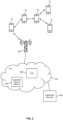
- Fig. 1 illustrates an exemplary scenario involving V2X communications.
- Fig. 1 shows various UEs 10, which may engage in V2X communication or other D2D communication, illustrated by solid arrows.
- Fig. 1 shows an access node 100 of a wireless communication network, e.g., an eNB of the LTE technology or a gNB of the NR technology, or an access point of a WLAN.
- a wireless communication network e.g., an eNB of the LTE technology or a gNB of the NR technology
- At least some of the UEs 10 may also be capable of communicating by using DL radio transmissions and/or UL radio transmissions, illustrated by broken arrows.
- the UEs 10 illustrated in Fig. 1 comprise vehicles, a drone, a mobile phone, and a person, e.g., a pedestrian, a cyclist, a driver of a vehicle, or a passenger of a vehicle.
- the radio transmissions may be performed by a communication module installed in the vehicle, and that in the case of the person the radio transmissions may be performed by a radio device carried or worn by the person, e.g., a wristband device or similar wearable device.
- V2X communication device or D2D communication device could be utilized as well, e.g., RSUs (roadside units) or other infrastructure based V2X communication devices, V2X communication devices based in an aircraft, like an airplane, or helicopter, in a spacecraft, in a train or car of a train, in a ship, in a motorcycles, in a bicycle, in a mobility scooter, or in any other kind of mobility or transportation device.
- the V2X communication may also involve utilizing the illustrated mechanisms for resource selection taking into account that at least some of the UEs 10 involved in the V2X communication may switch between an active reception state, in particular a DRX active state and a DRX inactive state.
- Fig. 2 illustrates an exemplary D2D communication scenario.
- Fig. 2 shows multiple UEs 10, which are connected to each other by radio links implementing direct wireless links (illustrated by double-headed arrows).
- one of the UEs 10 is connected by a radio link to an access node 100 of a wireless communication network, e.g., to an eNB of the LTE technology, or a gNB of the NR technology.
- the access node 100 is part of a RAN (Radio Access Network) of the wireless communication network, which typically also includes further access nodes to provide a desired coverage of the wireless communication network.
- Fig. 2 shows a core network (CN) 210 of the wireless communication network.
- the CN 210 may provide connectivity of the UEs 10 to other data networks, e.g., through a GW 220 provided in the CN 210. Further, the CN 210 may also include various nodes for controlling operation of the UEs 10.
- the radio links may be used for D2D communication between the UEs 10. Further, the radio link to the wireless communication network may be used for controlling or otherwise assisting the D2D communication. Further, the D2D communication and/or data communication with the wireless communication network may be used for providing various kinds of services to the UEs 10, e.g., a voice service, a multimedia service, a data service, an intelligent transportation system (ITS) or similar vehicular management or coordination service, an NSPS service, and/or an NCIS service. Such services may be based on applications which are executed on the UE 10 and/or on a device linked to the UE 10.
- ITS intelligent transportation system
- a D2D transmission may convey or correspond to a V2X message, an ITS message, or some other kind of message related to a service.
- Fig. 2 illustrates an application service platform 250 in the CN 210 of the wireless communication network.
- Fig. 2 illustrates one or more application servers 300 provided outside the wireless communication network.
- the application(s) executed on the UE 10 and/or on one or more other devices linked to the UE 10 may use the radio links with one or more other UEs 10, the application service platform 250, and/or the application server(s) 300, thereby enabling the corresponding service(s) on the UE 10.
- the services utilized by the UEs 10 may thus be hosted on the network side, e.g., on the application service platform 250 or on the application server(s) 300.
- some of the services may also network-independent so that they can be utilized without requiring an active data connection to the wireless communication network. This may for example apply to certain V2X or NSPS services. Such services may however still be assisted from the network side while the UE 10 is in coverage of the wireless communication network.
- the UEs 10 may apply the illustrated mechanisms for resource selection taking into account that at least some of the UEs 10 involved in the D2D communication may switch between an active reception state, in particular a DRX active state and a DRX inactive state.
- the UEs 10 are assumed to be a mobile phone and vehicles or vehicle-based communication devices, e.g., a vehicle-mounted or vehicle-integrated communication module, or a smartphone or other user device linked to vehicle systems.
- vehicle-based communication devices e.g., a vehicle-mounted or vehicle-integrated communication module, or a smartphone or other user device linked to vehicle systems.
- other types of UE could be used as well, e.g., a device carried by a pedestrian, or an infrastructure-based device, such as a roadside unit, like for example illustrated in Fig. 1 .
- Fig. 3 schematically illustrates an NSPS communication scenario.
- Fig. 3 shows multiple UEs 10, which may exchange NSPS messages associated with one or more NSPS services using D2D communication, e.g., based on the LTE sidelink communication or NR sidelink communication.
- the NSPS services may be assisted from the network, by exchanging NSPS messages via access node 100.
- the NSPS services may for example include group communication of rescue vehicles, rescue personnel or other equipment or personnel of public safety related organizations.
- Such communication may also involve utilizing the illustrated mechanisms for resource selection taking into account that at least some of the UEs 10 involved in the D2D communication may switch between an active reception state, in particular a DRX active state and a DRX inactive state.
- the D2D communication to which the illustrated resource allocation mechanism is applied may be based on the SL mode of the NR or LTE technology, using the PC5 radio interface.
- the SL communication may be based on multiple physical channels defined on a physical (PHY) layer of the radio interface between the TX UE and the RX UE, including a Physical sidelink control channel (PSCCH), a Physical sidelink shared channel (PSSCH), a Physical sidelink feedback channel (PSFCH), and a Physical sidelink broadcast channel (PSBCH).
- PHY Physical sidelink control channel
- PSSCH Physical sidelink shared channel
- PSFCH Physical sidelink feedback channel
- PSBCH Physical sidelink broadcast channel
- the data decoded from the PHY layer may then be further processed by an MAC (Medium Access Control) entity of the RX UE.
- MAC Medium Access Control
- the PSCCH carries only control information, usually referred to as the first-stage SCI (Sidelink Control Information). It is transmitted using a predefined format in predetermined radio resources, allowing a RX UE to use blind decoding. That is, a RX UE attempts to decode PSCCH according to the predefined format in the predetermined radio resources, without knowing beforehand whether a PSCCH was indeed transmitted or not. If the decoding operation succeeds, the RX UE assumes that a PSCCH was transmitted. Otherwise, it assumes no PSCCH was transmitted.
- the PSCCH carries information that is necessary to decode the PSSCH.
- the PSSCH carries both control information and data payload.
- the control information is usually referred to as the second-stage SCI. It is transmitted using the radio resource allocation and transmission format indicated in PSCCH. It contains further information that is necessary to decode the data payload carried by PSSCH too.
- the PSFCH carries only feedback information.
- the contents of PSFCH depends on the mode of HARQ operation. In some cases, both positive (also denoted as ACK) and negative (also denoted as NACK) acknowledgements are transmitted. In other cases, only NACK is transmitted.
- PSFCH transmission uses a predefined format and takes place in predetermined radio resources.
- the PSBCH carries basic system configuration information, e.g., concerning bandwidth, TDD (time-division duplexing) configuration, or the like. Further, the PSBCH carries synchronization signals.
- a typical operation may be as follows: A first UE performs an SL transmission on the PSCCH and PSSCH. The resources used for the SL transmission are selected by the first UE, e.g., using a sensing based resource selection process or using a resource selection process without sensing, such as a random selection based resource selection process. A second UE receives the SL transmission. Receiving the SL transmission may involve that, by means of blind decoding, the second UE detects the PSCCH and decodes the first-stage SCI carried by the PSCCH. If the blind decoding is successful, the second UE uses the decoded contents of the PSCCH to decode second-stage SCI carried by the PSSCH.
- the second UE uses the first-stage SCI and the second-stage SCI to decodes payload data carried by the PSSCH. Having successfully decoded the payload data, the second UE proceeds to transmit HARQ (Hybrid Automatic Repeat Request) feedback on the PSFCH.
- HARQ Hybrid Automatic Repeat Request
- Different modes of providing the HARQ feedback may be utilized.
- the first UE expects to receive the HARQ feedback from the second UE and may use the presence and contents of the PSFCH to determine further actions, e.g., whether to perform a retransmission or not. Accordingly, the PSDCH may be is used to trigger actions related to HARQ operation for the SL transmission.
- the utilization of the HARQ feedback may also be omitted in some cases.
- HARQ feedback is typically not utilized for SL transmissions in broadcast mode.
- the TX UE e.g., the first UE in the considered example
- the DRX operation for SL transmissions may be based on configuring, as part of a SL DRX configuration of the UE, one or more timers and parameters to control switching of the UE between the active time and the inactive time.
- these timers and parameters may include one or more of the following:
- SL DRX timers Due to their usage in controlling SL DRX operation, the above-mentioned timers may also be referred to as "SL DRX timers". It is noted that the names of the above timers and parameters may vary, and that the SL DRX configuration may also include various additional parameters.
- concepts as illustrated herein can be used by applying all the above parameters and timers defined of the SL DRX configuration or applying only a subset of them. For example, in some cases only a subset of all the parameters or timers may be configured or enabled.
- the SL DRX configuration may include parameters or timers related to HARQ but some of them might not be used if HARQ feedback is not utilized or disabled. Similarly, some of the parameters or timers might not be used if a maximum number of transmissions of a data packet is set to one or their usage might be limited based on a configured maximum number of retransmissions.
- a certain timer could be reset only K times, where K is the maximum number of transmissions for that data packet or a (pre-)configured maximum number of transmissions, e.g., (pre-)configured per SL resource pool.
- K is the maximum number of transmissions for that data packet or a (pre-)configured maximum number of transmissions, e.g., (pre-)configured per SL resource pool.
- some parameters or timers might not be in use if the SL transmission does not have associated SL HARQ feedback or if the grant or SL resource pool does not include resources for transmission of SL HARQ feedback.
- a sensing-based resource allocation utilized in illustrated concepts can be based on the following principles, which are compatible with the sensing based resource allocation as for example specified of the NR technology and may include the following sub-processes:
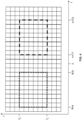
- Fig. 4 schematically illustrates the sensing window and the selection window in a time-frequency grid of radio resources.
- the radio resources may be organized in symbols, slots, frames, and/or subframes.
- the radio resources may be organized in subcarriers, resource elements, resource blocks, sub-channels, bandwidth parts, and/or bands.
- the grid elements illustrated in Fig. 4 may for example each correspond to one slot along the time coordinate t and one resource element along the frequency coordinate f.
- the sensing window is illustrated by a box with dotted outline
- the selection window is illustrated by a box with dashed outline.
- the sensing window has time boundaries defined by the parameters a and b and the selection window has time boundaries defined by the parameters T1 and T2. Further, the selection window and the sensing window each have a width extending between a lower frequency boundary f L and an upper frequency boundary f U , i.e., the selection window and the sensing window cover the same frequency resources. It is however noted that it would also be possible that the selection window and the sensing window differ with respect to the covered frequency sources.
- the selection window could have a lower frequency boundary f L1 and an upper frequency boundary f U1
- the sensing window has a lower frequency boundary f L2 and an upper frequency boundary f U2 , with f L2 being different from f L1 or f U2 being different from f U1 .
- the selection window and/or the sensing window could have non-rectangular form or be non-contiguous.
- the selection window or sensing window could consist of non-consecutive time slots.
- normal sensing and “partial sensing” may be used to distinguish resource selection procedures which use a partial window, e.g., partial sensing window and/or partial selection window, from other resource selection procedures refers to sensing using procedures based on a normal size of the sensing window and selection window.
- partial sensing is used to denote the procedures which are based on a partial sensing window and/or partial selection window
- normal sensing is used to denote the procedures that are based on a normal size of the sensing window and selection window.
- the partial sensing may also include the case that the size of the partial sensing window is zero, i.e., that the resource selection procedure does not use sensing of the resources to predict their utilization in the selection window.
- the normal sensing window can consist of consecutive time slots, while the partial sensing window consists of non-consecutive slots which are distributed over the normal sensing window.
- selection may refer to both an initial selection and a re-selection of resources. In some cases, where a distinction of a re-selection and other types of selection is intended, this may be explicitly indicated by using the term "re-selection”.
- deterministic active time is used to designate DRX active times of which are due to timers that are activated at predefined time instants, in particular triggered in a periodic manner.
- the deterministic active times may for example correspond to DRX active times caused by the above-mentioned drx-onDurationTimerSL of a long DRX cycle or a short DRX cycle of an SL DRX configuration.
- the behavior, in particular the time slots or symbols where the timer starts and expires, of such timer is rather well-defined.
- the timing may be described by a formula which depends on parameters like a DRX cycle period, defining how frequently the UE switches to the DRX active state, and an active time duration, defining for how long the UE is to remain in the DRX active state.
- some control signalling e.g., such as a DRX command MAC CE or the Long DRX command MAC CE, can be used to switch between the short and the long DRX cycles, for a UE with configured DRX at least one of the DRX cycles will be running and the timing of the corresponding drx-onDurationTimerSL will follow the configured behavior.
- condition active time is used to designate to active times which are due to timers that are only activated under a certain outcome of a preceding event, i.e., are event triggered.
- a timer resulting in a conditional active time could be triggered by an incoming transmission, by an outgoing transmission, by an expected retransmission, or the like.
- the behavior related to the timer is thus less predictable than for a periodically triggered timer.
- Examples of a timer resulting in a conditional active time are the above-mentioned drx-RetransmissionTimerSL and the drx-I nactivityTimerSL.
- the illustrated concepts involve that a resource selection procedure considers a DRX state of one or more potential RX UEs, in particular when a potential RX UE is in the DRX active state, and/or a DRX state of the TX UE, in particular when the TX UE is in the DRX active state.
- a resource selection procedure considers a DRX state of one or more potential RX UEs, in particular when a potential RX UE is in the DRX active state, and/or a DRX state of the TX UE, in particular when the TX UE is in the DRX active state.
- the overall procedure is aligned with the Mode 2 resource selection process of the LTE and NR technology and includes modifications in the form of steps 2a, 3a, and 4a. In some scenarios, only some of these modifications could be applied.
- the procedure could include the modification of step 2a, but not of steps 3a and 4a.
- the procedure could include the modification of step 3a, but not of steps 2a and 4a.
- the procedure could include the modification of step 4a, but not of steps 2a and 3a.
- Step 2a may involve that the TX UE senses resource(s) to perform resource selection for transmission(s) to the RX UE based on a set of resources for sensing.
- the set of resources for sensing may consist of the resources belonging to both the TX UE's sensing window and the TX UE's deterministic active times. Further, the set of resources for sensing may include resources belonging to one or conditional active times of the TX UE. For determining the set of resources for sensing, the TX UE may then consider whether its DRX active state is or will be triggered by an event like an incoming transmission at the TX UE, an outgoing transmission from the TX UE, an expected retransmission to the TX UE, or the like.
- step 2a The above functionalities described in connection with step 2a enable the TX UE to improve accuracy of the estimation of the expected occupation status. As a result, an improved the data rate and/or reliability of communication can be achieved.
- Step 3a may involve that the TX UE selects resource(s) fortransmission(s) to the RX UE based on a set of resources for selection.
- the set of resources for selection may consist of the resources belonging to both the TX UE's selection window and the RX UE's deterministic active times.
- the TX UE may determines the deterministic active times based on determining that the RX UE receives control signaling from the TX UE or from another entity such as a network node.
- control signaling may include a DRX command MAC CE or a Long DRX command MAC CE or a Wakeup signal or a wake up channel.
- such control signal may indicates that the RX UE needs to switch to a different DRX cycle, e.g., DRX cycle having a more frequent DRX active time, a DRX cycle having a less frequent DRX active time, a DRX cycle having a longer DRX active time, or a DRX cycle having a shorter DRX active time.
- the TX UE can include the resources corresponding to in the time slots while the drx-onDurationTimerSL or similar timer is running according to the new DRX cycle in the set of resources for selection, provided that these resources fall within the TX UE's selection window.
- the RX UE If the control signaling indicates that the RX UE needs to wake up from sleep state, the RX UE starts the drx-onDurationTimerSL or similar timer, and the TX UE includes the resources corresponding to the time slots while this timer is running in the set of resources for selection, provided that these resources fall within the TX UE's selection window.
- the set of resources for selection may include resources belonging to one or conditional active times of the TX UE. For determining the set of resources for selection, the TX UE may then consider whether the RX UE's DRX active state is or will be triggered by an event like an incoming transmission at the RX UE, an outgoing transmission from the RX UE, an expected retransmission to the RX UE, or the like.
- the TX UE may determine the RX UE's DRX state, in particular when it is in the DRX active state, in response to expected or planned transmission(s) from the TX UE to the RX UE. In some cases, the TX UE may determine a conditional active time of the RX UE based on sending of a scheduling assignment (SA) from the TX UE to the RX UE.
- SA scheduling assignment
- the SA may indicate radio resources to be used for a new SL transmission from the TX UE to the RX UE, and may trigger a timer associated with an conditional active time of the RX UE, e.g., to ensure that the RX UE is in the DRX active state when required for one or more potential retransmissions of the SL transmission.
- the TX UE may then include the resources corresponding to the time slots while this timer is running in the set of resources for selection when selecting resources for the retransmission or when selecting resources for a further new SL transmission.
- An example of such timer is the above-mentioned drx-RetransmissionTimerSL.
- the TX UE may determine the RX UE's DRX state, in particular when it is in the DRX active state, in response to failure of an SL transmission from the TX UE to the RX UE.
- the RX UE may fail to decode the SL transmission and send feedback to the TX UE to indicate the failure. Further, this event may trigger a timer associated with an conditional active time of the RX UE, e.g., to ensure that the RX UE is in the DRX active state when required for one or more potential retransmissions of the SL transmission.
- the TX UE may include the resources contained in the slots corresponding to this timer in the set of resources for selection when selecting resources for the retransmission(s) or when selecting resources for a further new SL transmission.
- An example of such timer is the above-mentioned drx-RetransmissionTimerSL.
- the TX UE may use the set of resources for selection determined based on the conditional active times when performing a re-selection of resources for the retransmission(s) of the initial SL transmission.
- the re-selection may be due to a pre-emption or a re-evaluation.
- the set of resources for selection when selecting the resources for the initial SL transmission may be based on only the deterministic active times of the RX UE, while the set of resources for selection when re-selecting the resources for the retransmission(s) may also include one or more conditional active times.
- the TX UE may consider if the RX UE has recently sent a scheduling request (SR), e.g., on the PUCCH (Physical Uplink Control Channel) or on the RACH (Random Access Channel), which is still pending.
- SR scheduling request
- the RX UE may inform the TX UE about such pending SR, and the TX UE may consider this information when determining the RX UE's DRX state, in particular when it is in the DRX active state.
- the TX UE may determine that the RX UE will be in the DRX active state until the SR is cancelled.
- the TX UE may assume that the RX UE remains in the DRX active state for a configured time period, e.g., while a corresponding timer is running.
- the TX UE may include the resources corresponding to the time slots of the conditional active period of the RX UE in the set of resources for selection, provided that these resources fall within the TX UE's selection window.
- step 3a The above functionalities described in connection with step 3a enable the TX UE to widen its basis of resources for the selection. As a result, an improved the data rate and/or reliability of communication can be achieved.
- Step 4a may involve that, when a resource selection for one or more SL transmissions is triggered while the TX UE it is in the DRX inactive state, the TX UE switches to the DRX active state or that when the resource selection is triggered while the TX UE already is in the DRX inactive state the TX UE prolongs its current active time.
- the TX UE may remain in the DRX active state until shortly before performing the intended SL transmission(s) to the RX UE.
- the TX UE may be enabled to continue estimating the occupation status of the resources by sensing and update its resource selection, e.g., via re-evaluation or re-selection. As a result, a risk of collisions may be further reduced.
- Figs. 5 and 6 show examples to further illustrate the above-described functionalities related to step 3a. These examples are based on the following assumptions:
- Fig. 5 shows an example for illustrating a resource selection process taking into account deterministic and conditional active times of the RX UE.
- blocks 521, 522, 524 denoted by "DRX ON" on the time line of the RX UE indicate deterministic active times
- blocks denoted by "DRX OFF" on the time line of the RX UE indicate when the RX UE is in the DRX inactive state.
- a hatched block 523 on the time line of the RX UE indicates a conditional active time caused by the drx-lnactivityTimerSL.
- a resource selection trigger at the TX UE occurs at time t1.
- the resource selection trigger may for example correspond to arrival of data in an SL TX buffer of the TX UE.
- the TX UE selects resources from a candidate set 511 formed by resources which correspond to the deterministic active time 521 of the RX UE and belong to the selection window 501 of the TX UE, which starts immediately after t1.
- the TX UE then needs to send a sequence of multiple SL transmissions to the RX UE, e.g., to convey a group of several packets. Such situation may for example occur for busty data traffic, such as voice traffic. Using SL transmissions for conveying voice traffic is for example considered for public safety use cases.
- the TX UE selects resources from a candidate set 512 including resources which correspond to the deterministic active time 522 of the RX UE and belong to the selection window 502 of the TX UE, which starts immediately after t2.
- the candidate set 512 also includes resources corresponding to the time slots 523 while the drx-lnactivityTimerSL is running.
- the TX UE can determine when the drx-lnactivityTimerSL timer will be triggered at the RX UE due to receiving the SA of the first SL transmission.
- the TX UE can count the slots corresponding to the duration of the drx-lnactivityTimerSL in the candidate set 512 and use this extended candidate set 512 when selecting resources for sending a retransmissions of the first SL transmission or for sending the subsequent SL transmissions of the sequence.
- D1 denotes an original duration of the deterministic active time 522
- D1 denotes the extension due to the conditional active time 523.
- Fig. 6 shows a further example for illustrating a resource selection process taking into account deterministic and conditional active times of the RX UE.
- blocks 621, 623 denoted by "DRX ON" on the time line of the RX UE indicate deterministic active times
- blocks denoted by "DRX OFF" on the time line of the RX UE indicate when the RX UE is in the DRX inactive state.
- a first hatched block 622 on the time line of the RX UE indicates an intermediate time interval corresponding to the drx-HARQ-RTT-TimerSL
- a second hatched block 623 on the time line of the RX UE indicates a conditional active time caused by the drx-RetransmissionTimerSL triggered after expiry of the drx-HARQ-RTT-TimerSL.
- the TX UE selects resources for an initial HARQ-feedback based SL transmission of payload data when a resource selection process is triggered at time t1.
- the resource selection process may for example be triggered by arrival of data in an SL TX buffer of the TX UE.
- the TX UE selects the resources for the initial transmission from a first candidate set 611.
- the first candidate set 611 includes resources which correspond to the deterministic active times 621, 623 of the RX UE and belong to a first selection window 601 of the TX UE, which starts immediately after t1.
- the initial SL transmission is illustrated by an arrow denoted by "DATA”
- HARQ feedback for the initial SL transmission is illustrated by an arrow denoted by "NACK”.
- NACK negative acknowledgement
- the example of Fig. 6 assumes that the RX UE fails to decode the initial SL transmission and sends indicates this by a negative acknowledgement (NACK).
- NACK negative acknowledgement
- the TX UE proceeds to select resources for the HARQ-feedback based retransmission of the initial SL transmission. In the example of Fig. 6 , this happens after the TX UE receives the HARQ feedback of the initial SL transmission.
- the TX UE performs selection of resources for the HARQ-feedback based retransmission at an earlier point of time, in particular already or before sending the initial SL transmission.
- the TX UE may pre-reserves resources for the retransmission under a conservative assumption that the RX UE will fail to decode the initial SL transmission.
- the TX UE can determine from, the received NACK when the drx-HARQ-RTT-TimerSL and the drx-RetransmissionTimerSL will be triggered at the RX UE. Accordingly, for the HARQ-feedback based retransmission, the TX UE selects resources from a second candidate set 612.
- the second candidate set 612 includes resources which correspond to the conditional active time 623 of the RX UE and belong to a second selection window 602 of the TX UE, which starts when the NACK triggers the resource selection process for the retransmission (or earlier as mentioned above). It is noted that in the example of Fig. 6 the transmission of the NACK causes termination of the ongoing deterministic active time 621, so that in the intermediate time interval corresponding to the drx-HARQ-RTT-TimerSL the RX UE is allowed to go to the DRX inactive state.
- a trigger for resource selection occurs at a first time instance t1.
- the resource selection process may for example be triggered by arrival of data in an SL TX buffer of the TX UE.
- the TX UE may then select resources for a number of n SL transmissions of payload data, e.g., for an initial transmission and one or more retransmissions.
- the TX UE may use a first candidate set of resources which consists of resources which correspond to one or more deterministic active times of the RX UE and belong to the current selection window of the TX UE.
- the selected resource for the initial SL transmission starts at a time instance t2>t1. If it is now assumed that during a resource re-evaluation period, which ends at time t2-T3, the UE detects that the selected resource for the retransmission needs to be re-selected, the TX UE proceeds to re-select resources for the retransmission in a second resource selection process.
- the TX UE may use a second candidate set of resources which includes of resources which correspond to one or more deterministic active times of the RX UE and resources which correspond to one or more conditional active times of the RX UE.
- conditional active times may for example be triggered like explained for the conditional active times 523, 623 in the examples of Figs. 5 and 6 .
- the initial SL transmission by the TX UE could not be correctly decoded by the RX UE, and this may trigger two actions at the RX UE: A) sending a negative acknowledgement, e.g., in the form of a HARQ-NACK, to the TX UE, and B) triggering one or more DRX timers, e.g., the above-mentioned drx-HARQ-RTT-TimerSL and subsequently the above-mentioned drx-RetransmissionTimerSL.
- the TX UE Upon receiving the negative acknowledgement, the TX UE is informed about the DRX timer(s) started or to be started by the RX UE.
- timers which cause the RX UE to be in the DRX active state e.g., timers related to CSI reporting, such as the above-mentioned drx-CSIReport-TimerSL or the above-mentioned drx-BlindRetransmissionTimerSL.
- Figs. 7A , 7B and 8 show an examples to further illustrate the above-described functionalities related to steps 2a and 4a.
- the TX UE extends its DRX active time occasion in response to triggering of a resource selection process for an SL transmission.
- the resource selection process may for example be triggered by arrival of data in an SL TX buffer of the TX UE.
- both the RX UE and the TX UE are switch between the DRX active state and the DRX inactive state.
- DRX active times in which the UE is in the DRX active state
- blocks denoted by "DRX ON” DRX active times, in which the UE is in the DRX inactive state, are illustrated by blocks denoted by "DRX OFF".
- the resource selection process is triggered at time t1, which is during the DRX active time 701 of the TX UE.
- the TX UE remains in the DRX active state and prolongs the DRX active time 701 until a time gap G before the TX UE performs the SL transmission, as illustrated by an arrow denoted by "DATA".
- D1 denotes the original duration of the DRX active time 701
- D2 denotes the duration corresponding to the prolongation of the DRX active time 701.
- the TX UE switches to the DRX active state occasion in response to triggering of a resource selection process for an SL transmission.
- the resource selection process may for example be triggered by arrival of data in an SL TX buffer of the TX UE.
- both the RX UE and the TX UE are switch between the DRX active state and the DRX inactive state.
- DRX active times in which the UE is in the DRX active state
- DRX active times in which the UE is in the DRX inactive state
- the resource selection process is triggered at time t1, which is during the DRX inactive time 711 of the TX UE.
- the TX UE switches to the DRX active state and enters DRX active time 712 which extends until a time gap G before the TX UE performs the SL transmission, as illustrated by an arrow denoted by "DATA".
- D1 denotes the original duration of the DRX inactive time 711.
- the TX UE may use some the DRX active times which occurred before triggering the resource selection process for partial or full sensing of the resources indicated by the TX UE's sensing window.
- the TX UE may switch to full sensing once the resource selection process is triggered and remain in the DRX active state until shortly before the intended SL transmission or for a certain duration.
- the TX UE may perform full or continuous sensing on in a monitoring time interval extending between the resource selection trigger and the SL transmission.
- Fig. 8 illustrates a an example of a corresponding resource selection process.
- a resource selection trigger e.g., arrival of data in an SL TX buffer, occurs at time t1.
- the TX UE performs partial sensing on a subset of resources 811 within a full sensing window 801. Based on the partial sensing, the TX UE performs an initial selection of resources.
- the resources 831 resulting from the initial selection are assumed to start at t2.
- the TX UE remains in the DRX active state for a monitoring time interval 821 and performs sensing on all resources for the purpose of re-evaluation of the initial resource selection. This re-evaluation can result in resource re-selection.
- the TX UE performs resource selection for its D2D transmissions based on a candidate set of resources which includes resources belonging to both the TX UE's selection window and one or more active times of the RX UE, in which the RX UE is in an active reception state.
- the one or more active times includes only deterministic active times of the RX UE, i.e., active times which are triggered in periodic manner.
- the one or more active times include both deterministic active times and one or more conditional active times of the RX UE.
- the TX UE can be configured or pre-configured to define which active times, e.g., only deterministic or both deterministic and conditional, or which type of conditional active time, are allowed to be included in the one or more active times.
- This configuration or pre-configuration may be based on signaling from a node of the wireless communication network, on network operator settings, and/or on manufacturer settings.
- the one or more active times include only one or more deterministic active times of the RX UE, whereas for a resource re-selection, e.g., for a retransmission, the one or more active times include both one or more deterministic active times and one or more conditional active times.
- the resource re-selection is triggered by resource re-evaluation and/or by resource pre-emption.
- the TX UE determines the RX UE's behavior in response to transmissions from the TX UE in one or more deterministic active times and used this information as a basis to determine which conditional active time is to be included in the one or more active times.
- a conditional active time could be included in the one or more active times in response to the TX UE determining that the associated timer will be triggered by the reception of an SA or SCI from the TX UE in a preceding deterministic active time. Further, a conditional active time could not be included in the one or more active times in response to the TX UE determining that the associated timer will be not triggered by the reception of an SA or SCI from the TX UE in a preceding deterministic active time. In some sub-variants, the corresponding determination at the TX UE whether to include a certain conditional DRX active time can be done based on the TX UE's transmission.
- a conditional active time could be included in response to being caused by an initial D2D transmission, but not if it is caused by a retransmission of an earlier D2D transmission.
- the corresponding determination at the TX UE whether to include a certain conditional DRX active time can be done based on channel conditions and/or priority of D2D transmissions.
- a certain conditional active time can be included in the one or more active times in response to the TX UE determining that the associated timer will be triggered if the RX UE fails to decode the data packet in a preceding active time.
- whether to include a certain conditional DRX active time can be based on feedback, in particular a NACK, from the RX UE.
- the feedback may for example correspond to HARQ feedback from the RX UE.
- a conditional active time can be included in the one or more active times in response to the TX UE determining that the RX UE has recently sent an SR, e.g., on the PUCCH or on the RACH, and the SR is still pending.
- the included conditional active time may be stopped in response to the TX UE determining that the RX UE has cancelled the SR.
- the included active time may be stopped in response to expiry of a timer.
- the determination at the TX UE whether to include a certain conditional DRX active time can also be based on a combination of two or more of the above-mentioned criteria.
- the TX UE includes a deterministic active time in the one or more active times in response to the TX UE determining that the associated timer is activated at the RX UE due to the RX UE receiving a control message from the TX UE or from another node, such as a network node.
- the control message may be a DRX Command MAC CE or a Long DRX Command MAC CE or a Wakeup signal or a Wakeup channel.
- an included conditional active time is used for selecting resources for the transmission of a new data packet or transport block.
- an included conditional active time is used for selecting resources for the retransmission(s) of the same data packet or transport block.
- an included conditional active time is used for selecting resources for both the retransmission(s) of the same data packet and the initial transmission of a data packet.
- an included conditional active time may be based on a timer corresponding to the above-mentioned the drx-lnactivityTimerSL.
- an included conditional active time may be based on a timer corresponding to the above-mentioned drx-RetransmissionTimerSL.
- an included deterministic active time may be based on a timer corresponding to the above-mentioned drx-onDurationTimer for a long DRX cycle and/or for a short DRX cycle.
- the selection window may be a selection window as defined for Mode 2 resource selection of NR SL communication.
- the TX UE decides based on a condition whether to include a certain conditional active time in the one or more active times.
- the conditional active time may be included in the one or more active times if the data packet or transport block for which the resource selection is being performed belongs to a certain QoS (Quality of Service) flow, or has a priority value lower than a certain threshold, or has a remaining packet delay budget smaller than a threshold.
- the conditional active time may be included in the one or more active times if the congestion level in the wireless communication network is above a certain threshold.
- corresponding conditions or corresponding thresholds in each condition may be applied, and these corresponding conditions or thresholds may differ from each other.
- the above conditions may be configured by a network node or pre-configured in the TX UE, e.g., based on operator settings, such as provided by a SIM (subscribed identity module), or based on manufacturer settings.
- SIM subscriber identity module
- the TX UE may prioritize selecting resources which are available during the deterministic active time(s).
- the prioritization could be performed on the physical layer when selecting the resources, on a MAC layer, e.g., when generating a sidelink grant, or on both the physical layer and the MAC layer.
- functionalities related to step 4a may include the following variants:
- the TX UE when a resource selection process is triggered, the TX UE enters the active reception state and remains in the active reception state until a time gap before a D2D transmission on a selected resource.
- a current active time where the TX UE is in the active reception state is extended until a time gap before a D2D transmission on a selected resource.
- the TX UE performs full or continuous sensing in a time window or monitoring time interval which starts at the resource selection trigger and ends at the time selected for transmission or at a time gap before the D2D transmission on a selected resource.
- a timer is activated at the TX UE when the resource selection is triggered. While the timer is running, the TX UE remains in the active state.
- the timer's duration is configured or preconfigured, e.g., based on signaling from a network node, based on operator settings, such as provided by a SIM, or based on manufacturer settings.
- the timer is stopped at a time gap before the D2D transmission in a selected resource.
- the duration of the timer is determined by the UE such that the UE remains in the active reception state until a time gap before the D2D transmission in a selected resource.
- the timer's duration is chosen according to the priority of the associated D2D transmission. For example, a longer duration may be chosen for transmission of higher priority and a shorter duration may be chosen for transmission of lower priority. In some sub-variants, the timer's duration may be chosen according to the congestion level in the system. For example, for a higher CBR (Channel Busy Ratio) value, a longer duration may be chosen. In some sub-variants, the timer's duration may be chosen based on combination of priority of transmission and congestion in the system, e.g., as indicated by a CBR value.
- CBR Channel Busy Ratio
- the time gap before the D2D transmission may be based on a switching time of the TX UE from reception mode to transmission mode.
- a timer may be activated at a first time gap before a periodic transmission and last for a certain duration. While the timer is running, the UE remains in the active reception state.
- the first time gap and the timer's duration are configured or preconfigured, e.g., based on signaling from a network node, based on operator settings, such as provided by a SIM, or based on manufacturer settings.
- the duration of the timer is determined by the UE such that the UE remains in the active reception state until a second time gap before the D2D transmission in the reserved resource.
- the first time gap and/or the timer's duration is chosen based on the priority of the associated D2D transmission. For example, with higher priority of the D2D transmission, a longer duration of the timer may be chosen, and with lower priority of the D2D transmission a shorter duration of the timer may be chosen.
- the timer's duration may be chosen according to the congestion level in the system, e.g., as indicated by a CBR value. For example, for a higher congestion level, a longer duration may be chosen.
- the timer's duration may be chosen based on a combination of priority of the D2D transmission and a congestion level in the system, e.g., as indicated by a CBR value.
- the TX UE may decide based on one or more conditions whether to enter and remain in the active reception state, or whether to prolong the current active time, or whether to start the timer for keeping the TX UE in the active reception state, or whether to perform continuous or full sensing after an initial resource selection or after a resource selection trigger.
- the one or more conditions may include a condition based on characteristics of the data traffic to be transmitted in the D2D transmission. For example, the TX UE may decide to enter and remain in active reception state, or to extend the current active time, or to start the timer if the data traffic has a priority value which is lower than a threshold or if the data traffic has a priority value which is higher than a threshold.
- the one or more conditions may be configured pre-configured at the TX UE, e.g., based on signaling from a network node, based on operator settings, such as provided by a SIM, or based on manufacturer settings.
- D2D transmissions to a single RX UE e.g., to unicast SL transmissions
- D2D transmissions to a group of multiple RX UEs e.g., to groupcast SL transmissions or to broadcast SL transmissions.
- the TX UE may determine the candidate set of resources based on considering the active reception times of the group of RX UEs, e.g., by determining the candidate set to correspond to time intervals during which at least a certain percentage X of the group is in the active reception state.
- the percentage X may be configured by signaling from the wireless communication network.
- the TX UE may determine the candidate set of resources based on considering the active reception times of RX UEs within a certain range Y from the TX UE, e.g., by determining the candidate set to correspond to time intervals during which at least a certain percentage Z of RX UEs within the range is in the active reception state.
- the range and/or the percentage Z may be configured by signaling from the wireless communication network.
- the range associated with the Sidelink transmission may be also configured by the gNB. Alternatively or in addition, the range may be determined based on QoS requirements of services or traffic types associated with the broadcast D2D transmission or broadcast SL transmission.
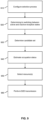
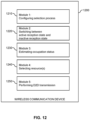
- Fig. 9 shows a flowchart for illustrating a method, which may be utilized for implementing the illustrated concepts.
- the method of Fig. 9 may be used for implementing the illustrated concepts in a wireless communication device, e.g., corresponding to any of the above-mentioned UEs.
- the wireless communication device may be a vehicle or vehicle-mounted device, but other types of WD, e.g., as mentioned above, could be used as well.
- the wireless communication device may for example be a UE for public safety operations, a UE that is mounted on a vehicle or is part of a vehicle.
- vehicle may be a car, a motorcycle, a drone, a bike, or the like.
- wireless communication device may also include a memory storing program code for implementing at least some of the below described functionalities or steps of the method of Fig. 9 .
- the wireless communication device may configure a selection process.
- the wireless communication device may configure the selection process with respect to active reception times to be considered in the selection process.
- the active reception times may be deterministic or conditional active times of DRX. However, the active reception times could also be active reception times of a UE power saving mode, or the like.
- the wireless communication device determines that a further wireless communication device is configured to switch between an inactive reception state and an active reception state, e.g., that the further wireless communication device is configured with DRX and thus is configured to switch between a DRX inactive state and an DRX active state.
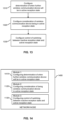
- the wireless communication device determines a candidate set of radio resources. This is accomplished based on when the further wireless communication device will be in the active reception state.
- the wireless communication device may determine based on control signaling to the further wireless communication device when the further wireless communication device will be in the active reception state.
- the control signaling may for example include control signaling from the wireless communication device. Alternatively or in addition the control signaling may include control signaling from a node of the wireless communication network. In some cases, the control signaling may include control signaling for configuring a duration of a timer for controlling switching of the further wireless communication device between the inactive reception state and the active reception state. In some cases, the control signaling may include control signaling for triggering switching between the inactive reception state and the active reception state.
- the wireless communication device determines based on one or more transmissions to the further wireless communication device when the further wireless communication device will be in the active reception state.
- the one or more transmissions to the further wireless communication device include one or more expected D2D transmissions from the wireless communication device to the further wireless communication device.
- the one or more expected D2D transmissions may for example include a D2D transmission scheduled by an assignment transmitted by the wireless communication device.
- the wireless communication device may the determine from the assignment when the further wireless communication device will be in the active reception state.
- the one or more expected D2D transmissions may include a D2D transmission on reserved radio resources. The wireless communication device may then determine from the reserved resources when the further wireless communication device will be in the active reception state.
- the one or more expected D2D transmissions may include a retransmission of another D2D transmission from the wireless communication device to the further wireless communication device.
- the retransmission could for example be triggered based on acknowledgement feedback from the further wireless communication device. In that case, the wireless communication device could determine from the acknowledgment feedback when the further wireless communication device will be in the active reception state.
- the retransmission could be scheduled based on a reservation of resources before sending the other D2D transmission. In that case, the wireless communication device could determine from the reservation when the further wireless communication device will be in the active reception state.
- the wireless communication device determine based on one or more transmissions from the further wireless communication device when the further wireless communication device will be in the active reception state.
- the one or more transmissions from the further wireless communication device may for example include an SR. In that case, the wireless communication device could determine that the further wireless communication device will be in the active reception state as long as the SR is pending.
- the candidate set of resources is based on one or more time intervals when the further wireless communication device will be in the active reception state.
- the one or more time intervals when the further wireless communication device will be in the active reception state may include at least one first time interval in which a periodically triggered first timer causes the further wireless communication device to be in the active reception state, e.g., like the above-mentioned deterministic active times.
- the one or more time intervals when the further wireless communication device will be in the active reception state may include at least one second time interval in which a second timer triggered by a D2D transmission to the further wireless communication device causes the further wireless communication device to be in the active reception state.
- the one or more time intervals when the further wireless communication device will be in the active reception state may include at least one third time interval in which a third timer triggered by a transmission from the further wireless communication device causes the further wireless communication device to be in the active reception state.
- the above-mentioned conditional active times are examples of the at least one second time interval and the at least one third time interval.
- step 930 may involve that depending on whether the D2D transmission from the wireless communication device to the further wireless communication device is a retransmission, the wireless communication device selects the one or more time intervals to include at least one second time interval in which a second timer triggered by a D2D transmission to the further wireless communication device causes the further wireless communication device to be in the active reception state and/or include at least one third time interval in which a third timer triggered by a transmission from the further wireless communication device causes the further wireless communication device to be in the active reception state.
- step 930 may involve that depending on whether the selection of the at least one radio resource is an initial selection or a re-selection, the wireless communication device selects the one or more time intervals to include at least one second time interval in which a second timer triggered by a D2D transmission to the further wireless communication device causes the further wireless communication device to be in the active reception state and/or include at least one third time interval in which a third timer triggered by a transmission from the further wireless communication device causes the further wireless communication device to be in the active reception state.
- step 930 may involve that depending on a priority of the D2D transmission from the wireless communication device to the further wireless communication device, the wireless communication device selects the one or more time intervals to include at least one second time interval in which a second timer triggered by a D2D transmission to the further wireless communication device causes the further wireless communication device to be in the active reception state and/or include at least one third time interval in which a third timer triggered by a transmission from the further wireless communication device causes the further wireless communication device to be in the active reception state.
- step 930 may involve that depending on a delay requirement, e.g., defined in terms of a remaining delay budget, of the D2D transmission from the wireless communication device to the further wireless communication device, the wireless communication device selects the one or more time intervals to include at least one second time interval in which a second timer triggered by a D2D transmission to the further wireless communication device causes the further wireless communication device to be in the active reception state and/or include at least one third time interval in which a third timer triggered by a transmission from the further wireless communication device causes the further wireless communication device to be in the active reception state.
- a delay requirement e.g., defined in terms of a remaining delay budget
- step 930 may involve that depending on a congestion level of radio resources, e.g., defined in terms of a CBR, the wireless communication device selecting the one or more time intervals to include at least one second time interval in which a second timer triggered by a D2D transmission to the further wireless communication device causes the further wireless communication device to be in the active reception state and/or include at least one third time interval in which a third timer triggered by a transmission from the further wireless communication device causes the further wireless communication device to be in the active reception state.
- a congestion level of radio resources e.g., defined in terms of a CBR
- step 930 may involve that depending on configuration information provided by the wireless communication network, e.g., as part of step 910, the wireless communication device selects the one or more time intervals to include at least one second time interval in which a second timer triggered by a D2D transmission to the further wireless communication device causes the further wireless communication device to be in the active reception state and/or include at least one third time interval in which a third timer triggered by a transmission from the further wireless communication device causes the further wireless communication device to be in the active reception state.
- step 930 may involve that the wireless communication device selects the candidate set of resources from a selection window indicating radio resources allowed to be used for a D2D transmission by the wireless communication device, e.g., a selection window as explained in connection with Fig. 4 .
- step 930 may involve that the wireless communication device determines the candidate set of radio resources based on when at least one of the group of further wireless communication device will be in the active reception state. In some cases, the wireless communication device may determine the candidate set of radio resources based on when at least minimum percentage of the group of further wireless communication device will be in the active reception state.
- the wireless communication device may estimate an expected occupation status of radio resources of the candidate set. This may involve monitoring radio resources, e.g., radio resources indicated by a sensing window. At least a part of the radio resources monitored by the wireless communication device may be indicated by a sensing window, e.g., a sensing window as explained in connection with Fig. 4 .
- the sensing window may be used for full sensing or for partial sensing.
- the wireless communication device is configured to switch between an inactive reception state and an active reception state.
- the wireless communication device may perform the monitoring of the radio resources to estimate the expected occupation status in response to a periodically triggered timer causing the wireless communication device to be in the active reception state, e.g., like explained above for the deterministic active times of the TX UE.
- the wireless communication device may perform the monitoring of the radio resources to estimate the expected occupation status in response to a D2D transmission received by the wireless communication device causing the wireless communication device to be in the active reception state, e.g., like explained above for the deterministic active times of the TX UE.
- the wireless communication device may perform the monitoring of the radio resources to estimate the expected occupation status in response to a D2D transmission from the wireless communication device causing the wireless communication device to be in the active reception state, e.g., like explained above for the deterministic active times of the TX UE.
- the wireless communication device may perform the monitoring of the radio resources to estimate the expected occupation status in response to an expected D2D transmission to the wireless communication device causing the wireless communication device to be in the active reception state, e.g., like explained above for the deterministic active times of the TX UE.
- the wireless communication device may perform the monitoring of the radio resources to estimate the expected occupation status in response to an expected retransmission of a D2D transmission to the wireless communication device causing the wireless communication device to be in the active reception state, e.g., like explained above for the deterministic active times of the TX UE.
- the switching between the inactive reception state and the active reception state may be controlled based on a need to perform the monitoring of the radio resources to estimate the expected occupation status of radio resources in the candidate set of radio resources.
- the wireless communication device could enter the active reception state if data arriving in a TX buffer triggers a resource selection process.
- step 940 may involve that, in response to a need to perform resource selection for the D2D transmission from the wireless communication device to the further wireless communication device, the wireless communication device controls the switching of the wireless communication device between the inactive reception state and the active reception state to continuously keep the wireless communication device in the active reception state for a monitoring interval. During the monitoring interval, the wireless communication device may then monitor radio resources to estimate the expected occupation status of radio resources in the candidate set of radio resources.
- the monitoring interval may have an end time defined by a time gap before the candidate set of radio resources determined at step 930. In some cases, the time gap before the candidate set of radio resources may depend on a time required to switch the wireless communication device from reception mode to transmission mode.
- the time gap before the candidate set of radio resources may be defined by network operator configuration or by pre-configuration of the wireless communication device.
- a duration of the monitoring interval is defined by network operator configuration or by pre-configuration of the wireless communication device.
- a duration of the monitoring interval may also depends on a priority of the D2D transmission from the wireless communication device to the further wireless communication device and/or on a congestion level of the radio resources.
- the monitoring interval may have a start time defined by a configured time gap before the at least one resource reserved for periodic D2D transmissions.
- the time gap before the at least one resource reserved for periodic D2D transmissions may be defined by network operator configuration or by pre-configuration of the wireless communication device, e.g., as part of step 910.
- the wireless communication device may select depending on at least one additional condition whether to control the switching of the wireless communication device between the inactive reception state and the active reception state to continuously keep the wireless communication device in the active reception state for the monitoring interval.
- the at least one additional condition comprises a condition related to a characteristic of data traffic to be conveyed in the D2D transmission from the wireless communication device to the further wireless communication device.
- the at least one additional condition may be defined by network operator configuration or by pre-configuration of the wireless communication device, e.g., as part of step 910.
- step 940 may involve that the wireless communication device already performed, from the candidate set of radio resources, an initial selection of the at least one radio resource for the D2D transmission from the wireless communication device to the further wireless communication device, based on the monitoring of the radio resources during the monitoring interval, the wireless communication device estimating the expected occupation status in the candidate set of radio resources, and based on the estimated expected occupation status, the wireless communication device performs, from the candidate set of radio resources, a re-selection of the at least one radio resource for the D2D transmission from the wireless communication device to the further wireless communication device.
- step 940 may involve that the wireless communication device monitors radio resources to obtain a first estimate of the expected occupation status of the radio resources in the candidate set of radio resources in response to the wireless communication device being caused to be in the active reception state by at least one of: a periodically triggered timer, a D2D transmission received by the wireless communication device, a D2D transmission from the wireless communication device, an expected D2D transmission to the wireless communication device, and an expected retransmission of a D2D transmission to the wireless communication device. Based on the first estimate of the expected occupation status, the wireless communication device may then perform, from the candidate set of radio resources, an initial selection of the at least one radio resource for the D2D transmission from the wireless communication device to the further wireless communication device.
- the wireless communication device may then obtain a second estimate of the expected occupation status in the candidate set of radio resources. Based on the second estimate of the expected occupation status, the wireless communication device may then perform, from the candidate set of radio resources, a re-selection of the at least one radio resource for the D2D transmission from the wireless communication device to the further wireless communication device.
- the monitoring interval may then have an end time defined by a time gap before the at least one radio resource selected in the initial selection.
- the time gap before the at least one radio resource selected in the initial selection may depend on a time required to switch the wireless communication device from reception mode to transmission mode.
- the time gap before the at least one radio resource selected in the initial selection may be defined by network operator configuration or by pre-configuration of the wireless communication device, e.g., as part of step 910.
- the wireless communication device selects at least one radio resource for a D2D transmission from the wireless communication device to the further wireless communication device.
- the wireless communication device selects the at least one radio resource from the candidate set determined at step 930. Further, the wireless communication device may select the at least one radio resource based on the expected occupation status estimated at step 940.
- the wireless communication device may perform the D2D transmission on the at least one radio resource selected at step 950.
- the D2D transmission from the wireless communication device to the further wireless communication device is a D2D transmission to a group of further wireless communication devices each configured to switch between an inactive reception state and an active reception state.
- the D2D transmission may be a groupcast transmission or a broadcast transmission.
- Fig. 10 shows a block diagram for illustrating functionalities of a wireless communication device 1000 which operates according to the method of Fig. 9 .
- the wireless communication device 1000 may for example correspond to any of the above-mentioned UEs.
- the wireless communication device 1000 may be provided with a module 1010 configured to configure a selection process, such as explained in connection with step 910.
- the wireless communication device 1000 device may be provided with a module 1020 configured to determine that further wireless communication device is configured to switch between an inactive reception state and an active reception state, such as explained in connection with step 920.
- the wireless communication device 1000 may be provided with a module 1030 configured to determine a candidate set of resources, such as explained in connection with step 930.
- the wireless communication device 1000 may be provided with a module 1040 configured to estimate an occupation status of radio resources, such as explained in connection with step 940. Further, the wireless communication device 1000 may be provided with a module 1050 configured to select at least one radio resource, such as explained in connection with step 950. Further, the wireless communication device 1000 may be provided with a module 1060 configured to perform a D2D transmission, such as explained in connection with step 960.
- the wireless communication device 1000 may include further modules for implementing other functionalities, such as known functionalities of a UE in the LTE and/or NR radio technology. Further, it is noted that the modules of the wireless communication device 1000 do not necessarily represent a hardware structure of the wireless communication device 1000, but may also correspond to functional elements, e.g., implemented by hardware, software, or a combination thereof.
- Fig. 11 shows a flowchart for illustrating a method, which may be utilized for implementing the illustrated concepts.
- the method of Fig. 11 may be used for implementing the illustrated concepts in a wireless communication device, e.g., corresponding to any of the above-mentioned UEs.
- the wireless communication device may be a vehicle or vehicle-mounted device, but other types of WD, e.g., as mentioned above, could be used as well.
- the wireless communication device may for example be a UE for public safety operations, a UE that is mounted on a vehicle or is part of a vehicle.
- vehicle may be a car, a motorcycle, a drone, a bike, or the like.
- wireless communication device may also include a memory storing program code for implementing at least some of the below described functionalities or steps of the method of Fig. 11 .
- the wireless communication device may configure a selection process.
- the wireless communication device may configure the selection process with respect to active reception times to be considered in the selection process.
- the active reception times may be deterministic or conditional active times of DRX. However, the active reception times could also be active reception times of a UE power saving mode, or the like.
- the wireless communication device switches between an inactive reception state and an active reception state.
- the wireless communication device may be configured with DRX and switch between a DRX inactive state and an DRX active state.
- the wireless communication device may estimate an expected occupation status of radio resources of a candidate set of radio resources. This may involve monitoring radio resources, e.g., radio resources indicated by a sensing window. At least a part of the radio resources monitored by the wireless communication device may be indicated by a sensing window, e.g., a sensing window as explained in connection with Fig. 4 .
- the sensing window may be used for full sensing or for partial sensing.
- the wireless communication device may perform the monitoring of the radio resources to estimate the expected occupation status in response to a periodically triggered timer causing the wireless communication device to be in the active reception state, e.g., like explained above for the deterministic active times of the TX UE.
- the wireless communication device may perform the monitoring of the radio resources to estimate the expected occupation status in response to a D2D transmission received by the wireless communication device causing the wireless communication device to be in the active reception state, e.g., like explained above for the deterministic active times of the TX UE.
- the wireless communication device may perform the monitoring of the radio resources to estimate the expected occupation status in response to a D2D transmission from the wireless communication device causing the wireless communication device to be in the active reception state, e.g., like explained above for the deterministic active times of the TX UE.
- the wireless communication device may perform the monitoring of the radio resources to estimate the expected occupation status in response to an expected D2D transmission to the wireless communication device causing the wireless communication device to be in the active reception state, e.g., like explained above for the deterministic active times of the TX UE.
- the wireless communication device may perform the monitoring of the radio resources to estimate the expected occupation status in response to an expected retransmission of a D2D transmission to the wireless communication device causing the wireless communication device to be in the active reception state, e.g., like explained above for the deterministic active times of the TX UE.
- the switching between the inactive reception state and the active reception state of step 1120 may be controlled based on a need to perform the monitoring of the radio resources to estimate the expected occupation status of radio resources in the candidate set of radio resources.
- the wireless communication device could enter the active reception state if data arriving in a TX buffer triggers a resource selection process.
- step 1130 may involve that, in response to a need to perform resource selection for the D2D transmission from the wireless communication device to the further wireless communication device, the wireless communication device controls the switching of the wireless communication device between the inactive reception state and the active reception state to continuously keep the wireless communication device in the active reception state for a monitoring interval.
- the wireless communication device may then monitor radio resources to estimate the expected occupation status of radio resources in the candidate set of radio resources.
- the monitoring interval may have an end time defined by a time gap before the candidate set of radio resources. In some cases, the time gap before the candidate set of radio resources may depend on a time required to switch the wireless communication device from reception mode to transmission mode.
- the time gap before the candidate set of radio resources may be defined by network operator configuration or by pre-configuration of the wireless communication device.
- a duration of the monitoring interval is defined by network operator configuration or by pre-configuration of the wireless communication device.
- a duration of the monitoring interval may also depends on a priority of the D2D transmission from the wireless communication device to the further wireless communication device and/or on a congestion level of the radio resources.
- the monitoring interval may have a start time defined by a configured time gap before the at least one resource reserved for periodic D2D transmissions.
- the time gap before the at least one resource reserved for periodic D2D transmissions may be defined by network operator configuration or by pre-configuration of the wireless communication device, e.g., as part of step 1110.
- the wireless communication device may select depending on at least one additional condition whether to control the switching of the wireless communication device between the inactive reception state and the active reception state to continuously keep the wireless communication device in the active reception state for the monitoring interval.
- the at least one additional condition comprises a condition related to a characteristic of data traffic to be conveyed in the D2D transmission from the wireless communication device to the further wireless communication device.
- the at least one additional condition may be defined by network operator configuration or by pre-configuration of the wireless communication device, e.g., as part of step 1110.
- step 1130 may involve that the wireless communication device already performed, from the candidate set of radio resources, an initial selection of the at least one radio resource for the D2D transmission from the wireless communication device to the further wireless communication device, based on the monitoring of the radio resources during the monitoring interval, the wireless communication device estimating the expected occupation status in the candidate set of radio resources, and based on the estimated expected occupation status, the wireless communication device performs, from the candidate set of radio resources, a re-selection of the at least one radio resource for the D2D transmission from the wireless communication device to the further wireless communication device.
- step 1130 may involve that the wireless communication device monitors radio resources to obtain a first estimate of the expected occupation status of the radio resources in the candidate set of radio resources in response to the wireless communication device being caused to be in the active reception state by at least one of: a periodically triggered timer, a D2D transmission received by the wireless communication device, a D2D transmission from the wireless communication device, an expected D2D transmission to the wireless communication device, and an expected retransmission of a D2D transmission to the wireless communication device. Based on the first estimate of the expected occupation status, the wireless communication device may then perform, from the candidate set of radio resources, an initial selection of the at least one radio resource for the D2D transmission from the wireless communication device to the further wireless communication device.
- the wireless communication device may then obtain a second estimate of the expected occupation status in the candidate set of radio resources. Based on the second estimate of the expected occupation status, the wireless communication device may then perform, from the candidate set of radio resources, a re-selection of the at least one radio resource for the D2D transmission from the wireless communication device to the further wireless communication device.
- the monitoring interval may then have an end time defined by a time gap before the at least one radio resource selected in the initial selection.
- the time gap before the at least one radio resource selected in the initial selection may depend on a time required to switch the wireless communication device from reception mode to transmission mode.
- the time gap before the at least one radio resource selected in the initial selection may be defined by network operator configuration or by pre-configuration of the wireless communication device, e.g., as part of step 1110.
- the wireless communication device selects at least one radio resource for a D2D transmission from the wireless communication device to the further wireless communication device.
- the wireless communication device selects the at least one radio resource from the candidate set, based on the expected occupation status estimated at step 1130.
- the wireless communication device may perform the D2D transmission on the at least one radio resource selected at step 1140.
- the D2D transmission from the wireless communication device to the further wireless communication device is a D2D transmission to a group of further wireless communication devices.
- the D2D transmission may be a groupcast transmission or a broadcast transmission.
- Fig. 12 shows a block diagram for illustrating functionalities of a wireless communication device 1200 which operates according to the method of Fig. 11 .
- the wireless communication device 1200 may for example correspond to any of the above-mentioned UEs.
- the wireless communication device 1200 may be provided with a module 1210 configured to configure a selection process, such as explained in connection with step 1110.
- the wireless communication device 1200 device may be provided with a module 1020 configured to switch between an inactive reception state and an active reception state of the wireless communication device, such as explained in connection with step 1120.
- the wireless communication device 1200 may be provided with a module 1130 configured to estimate an occupation status of radio resources, such as explained in connection with step 1130.
- the wireless communication device 1200 may be provided with a module 1240 configured to select at least one radio resource, such as explained in connection with step 1140. Further, the wireless communication device 1200 may be provided with a module 1250 configured to perform a D2D transmission, such as explained in connection with step 1150.
- the wireless communication device 1200 may include further modules for implementing other functionalities, such as known functionalities of a UE in the LTE and/or NR radio technology. Further, it is noted that the modules of the wireless communication device 1200 do not necessarily represent a hardware structure of the wireless communication device 1200, but may also correspond to functional elements, e.g., implemented by hardware, software, or a combination thereof.
- Fig. 13 shows a flowchart for illustrating a method, which may be utilized for implementing the illustrated concepts.
- the method of Fig. 13 may be used for implementing the illustrated concepts in a node of a wireless communication network, e.g., corresponding to the above-mentioned access node 100.
- the method of Fig. 13 may be used to configure a wireless communication device for operation according to the method of Fig. 9 and/or according to the method of Fig. 11 .
- At least some of the steps of the method of Fig. 13 may be performed and/or controlled by one or more processors of the node.
- Such node may also include a memory storing program code for implementing at least some of the below described functionalities or steps of the method of Fig. 13 .
- the node may configure the wireless communication device with respect to determination when a further wireless communication device will be in the active reception state. This may for example involve configuring selection of time intervals as explained in connection with step 930 of Fig. 9 .
- the node may configure the wireless communication device with respect to consideration when the wireless communication device is in the active reception state. This may for example involve configuration at which times the wireless communication device is to performing the monitoring of resources for estimating the expected occupation status, e.g., by configuring processes as described in connection with step 940 of Fig. 9 or processes as described in connection with step 1130 of Fig. 11 .
- the node may configure the wireless communication device with respect to controlling switching of the wireless communication device between in the inactive reception state and the active reception state. This may for example involve configuration for controlling the wireless communication device to continuously remain in the active reception state for a monitoring interval as described in connection with step 940 of Fig. 9 or processes as described in connection with step 1130 of Fig. 11 .
- Fig. 14 shows a block diagram for illustrating functionalities of a network node 1400 which operates according to the method of Fig. 13 .
- the network node 1400 may for example correspond to any of the above-mentioned access node 100.
- the network node 1400 may be provided with a module 1410 adapted to configure a wireless communication device with respect to determination when a further wireless communication device will be in the active reception state, such as explained in connection with step 1310.
- the network node 1400 may be provided with a module 1420 adapted to configure a wireless communication device with respect to consideration when the wireless communication device will be in the active reception state, such as explained in connection with step 1320.
- the network node 1400 may be provided with a module 1430 adapted to configure the wireless communication device with respect to controlling switching of the wireless communication device between in the inactive reception state and the active reception state, such as explained in connection with step 1330.
- the network node 1400 may include further modules for implementing other functionalities, such as known functionalities of an eNB in the LTE technology and/or of a gNB of the NR technology. Further, it is noted that the modules of the network node 1400 do not necessarily represent a hardware structure of the network node 1400, but may also correspond to functional elements, e.g., implemented by hardware, software, or a combination thereof.
- Figs. 9 to 14 may also be combined in various ways, e.g., in a system which includes one or more wireless communication devices operating according to the method of Fig. 9 and one or more wireless communication devices operating according to the method of Fig. 11 . Further, the functionalities could be combined in a system which includes one or more wireless communication devices operating according to the method of Fig. 9 or according to the method of Fig. 11 , and a node operating according to the method of Fig. 13 which is used to configure at least some at the wireless communication devices.
- Fig. 15 illustrates a processor-based implementation of a wireless communication device 1500 which may be used for implementing the above-described concepts.
- the structures as illustrated in Fig. 15 may be used for implementing the concepts in any of the above-mentioned UEs.
- the wireless communication device 1500 includes one or more radio interfaces 1510.
- the radio interface(s) 1510 may for example be based on the NR technology or the LTE technology.
- the radio interface(s) 1510 may support D2D communication, e.g., using SL communication as specified for the NR technology or the LTE technology.
- the wireless communication device 1500 may include one or more processors 1550 coupled to the radio interface(s) 1510 and a memory 1560 coupled to the processor(s) 1550.
- the radio interface(s) 1510, the processor(s) 1550, and the memory 1560 could be coupled by one or more internal bus systems of the wireless communication device 1500.
- the memory 1560 may include a Read-Only-Memory (ROM), e.g., a flash ROM, a Random Access Memory (RAM), e.g., a Dynamic RAM (DRAM) or Static RAM (SRAM), a mass storage, e.g., a hard disk or solid state disk, or the like.
- the memory 1560 may include software 1570 and/or firmware 1580.
- the memory 1560 may include suitably configured program code to be executed by the processor(s) 1550 so as to implement the above-described functionalities for controlling D2D communication, such as explained in connection with Figs. 9 to 12 .
- the structures as illustrated in Fig. 15 are merely schematic and that the wireless communication device 1500 may actually include further components which, for the sake of clarity, have not been illustrated, e.g., further interfaces, such as a dedicated management interface, or further processors.
- the memory 1560 may include further program code for implementing known functionalities of a UE.
- a computer program may be provided for implementing functionalities of the wireless communication device 1500, e.g., in the form of a physical medium storing the program code and/or other data to be stored in the memory 1560 or by making the program code available for download or by streaming.
- Fig. 16 illustrates a processor-based implementation of a node 1600 for a wireless communication network, which may be used for implementing the above-described concepts.
- the structures as illustrated in Fig. 16 may be used for implementing the concepts in any of the above-mentioned access nodes.
- the node 1600 may include one or more radio interfaces 1610.
- the radio interface(s) 1610 may for example be based on the NR technology or the LTE technology.
- the radio interface(s) 1610 may be used for controlling wireless communication devices, such as any of the above-mentioned UEs.
- the node 1600 may include one or more network interfaces 1620.
- the network interface(s) 1620 may for example be used for communication with one or more other nodes of the wireless communication network.
- the network interface(s) 1620 may be used for controlling wireless communication devices, such as any of the above-mentioned UEs.
- the node 1600 may include one or more processors 1650 coupled to the interface(s) 1610, 1620 and a memory 1660 coupled to the processor(s) 1650.
- the interface(s) 1610, the processor(s) 1650, and the memory 1660 could be coupled by one or more internal bus systems of the node 1600.
- the memory 1660 may include a ROM, e.g., a flash ROM, a RAM, e.g., a DRAM or SRAM, a mass storage, e.g., a hard disk or solid state disk, or the like.
- the memory 1660 may include software 1670 and/or firmware 1680.
- the memory 1660 may include suitably configured program code to be executed by the processor(s) 1650 so as to implement the above-described functionalities for controlling D2D communication, such as explained in connection with Figs. 13 and 14 .
- the structures as illustrated in Fig. 16 are merely schematic and that the node 1600 may actually include further components which, for the sake of clarity, have not been illustrated, e.g., further interfaces, such as a dedicated management interface, or further processors.
- the memory 1660 may include further program code for implementing known functionalities of an eNB or of a gNB.
- a computer program may be provided for implementing functionalities of the node 1600, e.g., in the form of a physical medium storing the program code and/or other data to be stored in the memory 1660 or by making the program code available for download or by streaming.
- the concepts as described above may be used for enabling efficient resource selection for D2D communication.
- the concepts may help to minimize adverse impacts of DRX or similar procedures involving temporary switching to an inactive reception state.
- the concepts may be applied in connection with various types of existing resource selection processes or existing DRX mechanisms.
- the illustrated concepts may be applied in connection with various kinds of radio technologies and D2D communication, without limitation the SL mode of the LTE technology or NR technology, e.g., in connection with WLAN technologies or other wireless ad-hoc network technologies.
- the concepts may be applied with respect to various types of UEs, without limitation to vehicle-based UEs.
- the concepts may be applied in connection with various services supported by D2D communication, without limitation to V2X, NSPS, or NCIS.
Landscapes
- Engineering & Computer Science (AREA)
- Computer Networks & Wireless Communication (AREA)
- Signal Processing (AREA)
- Mobile Radio Communication Systems (AREA)
- Transceivers (AREA)
Claims (20)
- Verfahren zur Steuerung von Vorrichtung-zu-Vorrichtung-Kommunikation, D2D-Kommunikation, in einem Drahtloskommunikationsnetzwerk, wobei das Verfahren umfasst, dass:eine drahtlose Kommunikationsvorrichtung (10; 1000; 1500) bestimmt, dass eine weitere drahtlose Kommunikationsvorrichtung (10; 1000; 1200; 1500) so konfiguriert ist, dass sie zwischen einem inaktiven Empfangszustand und einem aktiven Empfangszustand wechselt;die drahtlose Kommunikationsvorrichtung (10; 1000; 1500) basierend auf einer oder mehreren voraussichtlichen Übertragungen an die weitere drahtlose Kommunikationsvorrichtung (10; 1000; 1200; 1500) bestimmt, wann sich die weitere drahtlose Kommunikationsvorrichtung (10; 1000; 1200; 1500) im aktiven Empfangszustand befindet;die drahtlose Kommunikationsvorrichtung (10; 1000; 1500) basierend darauf, wann sich die weitere drahtlose Kommunikationsvorrichtung (10; 1000; 1200; 1500) im aktiven Empfangszustand befindet, einen Kandidatensatz von Funkressourcen bestimmt; unddie drahtlose Kommunikationsvorrichtung (10; 1000; 1500) aus dem Kandidatensatz von Funkressourcen mindestens eine Funkressource für eine D2D-Übertragung von der drahtlosen Kommunikationsvorrichtung (10; 1000; 1500) an die weitere drahtlose Kommunikationsvorrichtung (10; 1000; 1200; 1500) auswählt.
- Verfahren nach Anspruch 1,
wobei das Bestimmen, wann sich die weitere drahtlose Kommunikationsvorrichtung (10; 1000; 1200; 1500) im aktiven Empfangszustand befindet, ferner auf Steuersignalisierung an die weitere drahtlose Kommunikationsvorrichtung (10; 1000; 1200; 1500) basiert. - Verfahren nach Anspruch 2,
wobei die Steuersignalisierung an die weitere drahtlose Kommunikationsvorrichtung (10; 1000; 1200; 1500) Steuersignalisierung von der drahtlosen Kommunikationsvorrichtung (10; 1000; 1500) und/oder Steuersignalisierung von einem Knoten (100; 1400; 1600) des Drahtloskommunikationsnetzwerks und/oder Steuersignalisierung zum Konfigurieren einer Dauer eines Zeitgebers zum Steuern des Wechsels der weiteren drahtlosen Kommunikationsvorrichtung (10; 1000; 1200; 1500) zwischen dem inaktiven Empfangszustand und dem aktiven Empfangszustand und/oder Steuersignalisierung zum Auslösen des Wechsels zwischen dem inaktiven Empfangszustand und dem aktiven Empfangszustand umfasst. - Verfahren nach einem der Ansprüche 1 bis 3,
wobei die eine oder die mehreren voraussichtlichen D2D-Übertragungen eine D2D-Übertragung, die durch eine von der drahtlosen Kommunikationsvorrichtung (10; 1000; 1500) gesendeten Zuordnung disponiert wird, oder eine D2D-Übertragung auf reservierten Funkressourcen umfassen. - Verfahren nach einem der Ansprüche 1 bis 4,
wobei die eine oder die mehreren voraussichtlichen D2D-Übertragungen eine Neuübertragung einer anderen D2D-Übertragung von der drahtlosen Kommunikationsvorrichtung (10; 1000; 1500) an die weitere drahtlose Kommunikationsvorrichtung (10; 1000; 1200; 1500) umfassen. - Verfahren nach Anspruch 5,
wobei die Neuübertragung basierend auf einer Bestätigungsrückmeldung von der weiteren drahtlosen Kommunikationsvorrichtung (10; 1000; 1200; 1500) ausgelöst wird. - Verfahren nach einem der Ansprüche 1 bis 6,
wobei der Kandidatensatz von Funkressourcen auf einem oder mehreren Zeitintervallen basiert, in denen sich die weitere drahtlose Kommunikationsvorrichtung (10; 1000; 1200; 1500) im aktiven Empfangszustand befindet. - Verfahren nach Anspruch 7,wobei das eine oder die mehreren Zeitintervalle, in denen sich die weitere drahtlose Kommunikationsvorrichtung (10; 1000; 1200; 1500) im aktiven Empfangszustand befindet, mindestens ein erstes Zeitintervall umfasst, in dem ein periodisch ausgelöster erster Zeitgeber die weitere drahtlose Kommunikationsvorrichtung (10; 1000; 1200; 1500) in den aktiven Empfangszustand versetzt, und/oderwobei das eine oder die mehreren Zeitintervalle, in denen sich die weitere drahtlose Kommunikationsvorrichtung (10; 1000; 1200; 1500) im aktiven Empfangszustand befindet, mindestens ein zweites Zeitintervall umfasst, in dem ein durch eine D2D-Übertragung an die weitere drahtlose Kommunikationsvorrichtung (10; 1000; 1200; 1500) ausgelöster zweiter Zeitgeber die weitere drahtlose Kommunikationsvorrichtung (10; 1000; 1200; 1500) in den aktiven Empfangszustand versetzt, und/oderwobei das eine oder die mehreren Zeitintervalle, in denen sich die weitere drahtlose Kommunikationsvorrichtung (10; 1000; 1200; 1500) im aktiven Empfangszustand befindet, mindestens ein drittes Zeitintervall umfasst, in dem ein durch eine Übertragung von der weiteren drahtlosen Kommunikationsvorrichtung (10; 1000; 1200; 1500) ausgelöster dritter Zeitgeber die weitere drahtlose Kommunikationsvorrichtung (10; 1000; 1200; 1500) in den aktiven Empfangszustand versetzt.
- Verfahren nach Anspruch 7 oder 8, umfassend, dass:
in Abhängigkeit davon, ob die D2D-Übertragung von der drahtlosen Kommunikationsvorrichtung an die weitere drahtlose Kommunikationsvorrichtung (10; 1000; 1200; 1500) eine Neuübertragung ist, die drahtlose Kommunikationsvorrichtung (10; 1000; 1500) das eine oder die mehreren Zeitintervalle so auswählt, dass sie mindestens ein zweites Zeitintervall umfassen, in dem ein durch eine D2D-Übertragung an die weitere drahtlose Kommunikationsvorrichtung (10; 1000; 1200; 1500) ausgelöster zweiter Zeitgeber die weitere drahtlose Kommunikationsvorrichtung (10; 1000; 1200; 1500) in den aktiven Empfangszustand versetzt, und/oder mindestens ein drittes Zeitintervall umfassen, in dem ein durch eine Übertragung von der weiteren drahtlosen Kommunikationsvorrichtung (10; 1000; 1200; 1500) ausgelöster dritter Zeitgeber die weitere drahtlose Kommunikationsvorrichtung (10; 1000; 1200; 1500) in den aktiven Empfangszustand versetzt. - Verfahren nach einem der Ansprüche 7 bis 9, umfassend, dass:
in Abhängigkeit davon, ob die Auswahl der mindestens einen Funkressource eine Erstauswahl oder eine Neuauswahl ist, die drahtlose Kommunikationsvorrichtung (10; 1000; 1500) das eine oder die mehreren Zeitintervalle so auswählt, dass sie mindestens ein zweites Zeitintervall umfassen, in dem ein durch eine D2D-Übertragung an die weitere drahtlose Kommunikationsvorrichtung (10; 1000; 1200; 1500) ausgelöster zweiter Zeitgeber die weitere drahtlose Kommunikationsvorrichtung (10; 1000; 1200; 1500) in den aktiven Empfangszustand versetzt, und/oder mindestens ein drittes Zeitintervall umfassen, in dem ein durch eine Übertragung von der weiteren drahtlosen Kommunikationsvorrichtung (10; 1000; 1200; 1500) ausgelöster dritter Zeitgeber die weitere drahtlose Kommunikationsvorrichtung (10; 1000; 1200; 1500) in den aktiven Empfangszustand versetzt. - Verfahren nach einem der Ansprüche 1 bis 10,wobei die drahtlose Kommunikationsvorrichtung (10; 1000; 1500) Funkressourcen überwacht, um einen voraussichtlichen Belegungsstatus von Funkressourcen im Kandidatensatz von Funkressourcen zu schätzen; und die drahtlose Kommunikationsvorrichtung (10; 1000; 1500) basierend auf dem geschätzten voraussichtlichen Belegungsstatus der Funkressourcen im Kandidatensatz von Funkressourcen die mindestens ein Funkressource für die D2D-Übertragung von der drahtlosen Kommunikationsvorrichtung (10; 1000; 1500) an die weitere drahtlose Vorrichtung (10; 1000; 1200; 1500) auswählt,wobei die drahtlose Kommunikationsvorrichtung (10; 1000; 1500) so konfiguriert ist, dass sie zwischen einem inaktiven Empfangszustand und einem aktiven Empfangszustand wechselt,wobei das Wechseln zwischen dem inaktiven Empfangszustand und dem aktiven Empfangszustand basierend auf einer Notwendigkeit gesteuert wird, die Überwachung der Funkressourcen durchführen zu müssen, um den voraussichtlichen Belegungsstatus von Funkressourcen im Kandidatensatz von Funkressourcen zu schätzen.
- Verfahren nach Anspruch 11, umfassend, dass:in Reaktion auf eine Notwendigkeit, Ressourcenauswahl für die D2D-Übertragung von der drahtlosen Kommunikationsvorrichtung (10; 1000; 1500) an die weitere drahtlose Kommunikationsvorrichtung (10; 1000; 1200; 1500) durchführen zu müssen, die drahtlose Kommunikationsvorrichtung (10; 1000; 1500) das Wechseln der drahtlosen Kommunikationsvorrichtung (10; 1000; 1500) zwischen dem inaktiven Empfangszustand und dem aktiven Empfangszustand so steuert, dass sie die drahtlose Kommunikationsvorrichtung (10; 1000; 1500) für ein Überwachungsintervall kontinuierlich im aktiven Empfangszustand hält; unddie drahtlose Kommunikationsvorrichtung (10; 1000; 1500) während des Überwachungsintervalls Funkressourcen überwacht, um den voraussichtlichen Belegungsstatus von Funkressourcen im Kandidatensatz von Funkressourcen zu schätzen.
- Verfahren nach Anspruch 12,
wobei eine Dauer des Überwachungsintervalls von einer Priorität der D2D-Übertragung von der drahtlosen Kommunikationsvorrichtung (10; 1000; 1500) an die weitere drahtlose Kommunikationsvorrichtung (10; 1000; 1200; 1500) und/oder von einem Überlastgrad der Funkressourcen abhängt. - Verfahren nach Anspruch 12 oder 13, umfassend, dass:die drahtlose Kommunikationsvorrichtung (10; 1000; 1500) Funkressourcen überwacht, um eine erste Schätzung des voraussichtlichen Belegungsstatus der Funkressourcen im Kandidatensatz von Funkressourcen zu erhalten, in Reaktion darauf, dass die drahtlose Kommunikationsvorrichtung (10; 1000; 1500) durch mindestens eines von Folgenden in den aktiven Empfangszustand versetzt wird: einen periodisch ausgelösten Zeitgeber, eine durch die drahtlose Kommunikationsvorrichtung (10; 1000; 1500) empfangene D2D-Übertragung, eine D2D-Übertragung von der drahtlosen Kommunikationsvorrichtung (10; 1000; 1500), eine voraussichtliche D2D-Übertragung an die drahtlose Kommunikationsvorrichtung (10; 1000; 1500) und eine voraussichtliche Neuübertragung einer D2D-Übertragung an die drahtlose Kommunikationsvorrichtung (10; 1000; 1500) ;die drahtlose Kommunikationsvorrichtung (10; 1000; 1500) basierend auf der Schätzung des voraussichtlichen Belegungsstatus aus dem Kandidatensatz von Funkressourcen eine Erstauswahl der mindestens einen Funkressource für die D2D-Übertragung von der drahtlosen Kommunikationsvorrichtung (10; 1000; 1500) an die weitere drahtlose Kommunikationsvorrichtung (10; 1000; 1200; 1500) durchführt;die drahtlose Kommunikationsvorrichtung (10; 1000; 1500) basierend auf der Überwachung der Funkressourcen während des Überwachungsintervalls eine zweite Schätzung des voraussichtlichen Belegungsstatus im Kandidatensatz von Funkressourcen erhält; unddie drahtlose Kommunikationsvorrichtung (10; 1000; 1500) basierend auf der zweiten Schätzung des voraussichtlichen Belegungsstatus aus dem Kandidatensatz von Funkressourcen eine Neuauswahl der mindestens einen Funkressource für die D2D-Übertragung von der drahtlosen Kommunikationsvorrichtung (10; 1000; 1500) an die weitere drahtlose Kommunikationsvorrichtung (10; 1000; 1200; 1500) durchführt.
- Verfahren nach einem der Ansprüche 11 bis 14,
wobei zumindest ein Teil der von der drahtlosen Kommunikationsvorrichtung (10; 1000; 1500) überwachten Funkressourcen durch ein Messfenster angezeigt wird. - Verfahren nach einem der Ansprüche 1 bis 15,wobei die D2D-Übertragung von der drahtlosen Kommunikationsvorrichtung (10; 1000; 1500) an die weitere drahtlose Kommunikationsvorrichtung (10; 1000; 1200; 1500) eine D2D-Übertragung an eine Gruppe von weiteren drahtlosen Kommunikationsvorrichtungen (10; 1000; 1200; 1500) ist, die jeweils so konfiguriert sind, dass sie zwischen einem inaktiven Empfangszustand und einem aktiven Empfangszustand wechseln, undwobei die drahtlose Kommunikationsvorrichtung (10; 1000; 1500) den Kandidatensatz von Funkressourcen basierend darauf bestimmt, wann sich mindestens eine der Gruppe von weiteren drahtlosen Kommunikationsvorrichtungen (10; 1000; 1200; 1500) im aktiven Empfangszustand befindet.
- Drahtlose Kommunikationsvorrichtung (10; 1000; 1500), wobei die drahtlose Kommunikationsvorrichtung (10; 1000; 1500) konfiguriert ist zum:Bestimmen, das eine weitere drahtlose Kommunikationsvorrichtung (10; 1000; 1200; 1500) so konfiguriert ist, dass sie zwischen einem inaktiven Empfangszustand und einem aktiven Empfangszustand wechselt;basierend auf einer oder mehreren voraussichtlichen Übertragungen an die weitere drahtlose Kommunikationsvorrichtung (10; 1000; 1200; 1500), Bestimmen, wann sich die weitere drahtlose Kommunikationsvorrichtung (10; 1000; 1200; 1500) im aktiven Empfangszustand befindet;basierend darauf, wann sich die weitere drahtlose Kommunikationsvorrichtung (10; 1000; 1200; 1500) im aktiven Empfangszustand befindet, Bestimmen eines Kandidatensatzes von Funkressourcen; undAuswählen mindestens einer Funkressource für eine D2D-Übertragung von der drahtlosen Kommunikationsvorrichtung (10; 1000; 1500) an die weitere drahtlose Kommunikationsvorrichtung (10; 1000; 1200; 1500)aus dem Kandidatensatz von Funkressourcen.
- Drahtlose Kommunikationsvorrichtung (10; 1000; 1500) nach Anspruch 17, wobei die drahtlose Kommunikationsvorrichtung (10; 1000; 1500) zum Durchführen eines Verfahrens nach einem der Ansprüche 2 bis 16 konfiguriert ist.
- Drahtlose Kommunikationsvorrichtung (10; 1000; 1500) nach Anspruch 17 oder 18, wobei die drahtlose Vorrichtung (10; 1000; 1500) ein verbundenes Fahrzeug ist.
- Computerprogramm oder Computerprogrammprodukt, umfassend Programmcode, der von mindestens einem Prozessor einer drahtlosen Kommunikationsvorrichtung (10; 1000; 1200; 1500) auszuführen ist, wobei die Ausführung des Programmcodes die drahtlose Kommunikationsvorrichtung (10; 1000; 1200; 1500) zum Durchführen eines Verfahrens nach einem der Ansprüche 1 bis 16 veranlasst.
Priority Applications (1)
| Application Number | Priority Date | Filing Date | Title |
|---|---|---|---|
| EP24221086.2A EP4550927A3 (de) | 2020-09-11 | 2021-09-10 | Berücksichtigung des aktiven empfangsstatus bei der ressourcenauswahl für d2d-kommunikation |
Applications Claiming Priority (2)
| Application Number | Priority Date | Filing Date | Title |
|---|---|---|---|
| CN2020114809 | 2020-09-11 | ||
| PCT/EP2021/074959 WO2022053627A1 (en) | 2020-09-11 | 2021-09-10 | Consideration of active reception status in resource selection for d2d communication |
Related Child Applications (1)
| Application Number | Title | Priority Date | Filing Date |
|---|---|---|---|
| EP24221086.2A Division EP4550927A3 (de) | 2020-09-11 | 2021-09-10 | Berücksichtigung des aktiven empfangsstatus bei der ressourcenauswahl für d2d-kommunikation |
Publications (3)
| Publication Number | Publication Date |
|---|---|
| EP4211980A1 EP4211980A1 (de) | 2023-07-19 |
| EP4211980B1 true EP4211980B1 (de) | 2024-12-25 |
| EP4211980C0 EP4211980C0 (de) | 2024-12-25 |
Family
ID=77910790
Family Applications (2)
| Application Number | Title | Priority Date | Filing Date |
|---|---|---|---|
| EP21777269.8A Active EP4211980B1 (de) | 2020-09-11 | 2021-09-10 | Berücksichtigung des aktiven empfangsstatus bei der ressourcenauswahl für d2d-kommunikation |
| EP24221086.2A Pending EP4550927A3 (de) | 2020-09-11 | 2021-09-10 | Berücksichtigung des aktiven empfangsstatus bei der ressourcenauswahl für d2d-kommunikation |
Family Applications After (1)
| Application Number | Title | Priority Date | Filing Date |
|---|---|---|---|
| EP24221086.2A Pending EP4550927A3 (de) | 2020-09-11 | 2021-09-10 | Berücksichtigung des aktiven empfangsstatus bei der ressourcenauswahl für d2d-kommunikation |
Country Status (4)
| Country | Link |
|---|---|
| US (1) | US20230319950A1 (de) |
| EP (2) | EP4211980B1 (de) |
| CN (2) | CN116963313A (de) |
| WO (1) | WO2022053627A1 (de) |
Cited By (1)
| Publication number | Priority date | Publication date | Assignee | Title |
|---|---|---|---|---|
| EP3989647A1 (de) * | 2020-10-23 | 2022-04-27 | Robert Bosch GmbH | Verfahren und vorrichtungen zur funkkommunikation |
Families Citing this family (4)
| Publication number | Priority date | Publication date | Assignee | Title |
|---|---|---|---|---|
| US11844065B2 (en) * | 2020-09-24 | 2023-12-12 | Qualcomm Incorporated | Sidelink discontinuous reception (DRX) operations |
| KR20230053654A (ko) * | 2020-09-25 | 2023-04-21 | 엘지전자 주식회사 | Nr v2x에서 sl drx 설정의 비활성 구간을 사용한 동작 방법 및 장치 |
| EP4271101A4 (de) * | 2020-12-24 | 2024-11-06 | LG Electronics Inc. | Verfahren und vorrichtung zur übertragung von sl-drx-mac-ce in nr v2x |
| MX2023007473A (es) * | 2021-01-18 | 2023-07-04 | Panasonic Ip Corp America | Aparatos de comunicacion y metodos de comunicacion para ventanas de seleccion y deteccion para equipos de usuario (ue) de enlace lateral de nueva radio (nr) con deteccion parcial. |
Citations (1)
| Publication number | Priority date | Publication date | Assignee | Title |
|---|---|---|---|---|
| EP3316536A1 (de) * | 2015-06-29 | 2018-05-02 | LG Electronics Inc. | Verfahren zum senden/empfangen eines empfangenen d2d-signals in einem drahtloskommunikationssystem und vorrichtung dafür |
Family Cites Families (7)
| Publication number | Priority date | Publication date | Assignee | Title |
|---|---|---|---|---|
| KR102011823B1 (ko) * | 2015-07-03 | 2019-08-19 | 엘지전자 주식회사 | 단말 간 신호를 전송하는 방법 및 이를 위한 장치 |
| CN108307489A (zh) * | 2016-08-11 | 2018-07-20 | 中兴通讯股份有限公司 | 信息处理方法、装置、用户设备及基站 |
| WO2018064477A1 (en) * | 2016-09-30 | 2018-04-05 | Intel IP Corporation | Systems and methods for discontinuous reception in device-to-device communication |
| CN113179674B (zh) * | 2018-09-26 | 2025-01-17 | 弗劳恩霍夫应用研究促进协会 | V2x动态组播资源分配 |
| CN113225847B (zh) * | 2020-01-21 | 2023-10-24 | 华硕电脑股份有限公司 | 考虑不连续接收操作处理装置间资源选择的方法和设备 |
| CN115380603B (zh) * | 2020-02-13 | 2023-10-31 | 皇家飞利浦有限公司 | 资源检索程序 |
| WO2021179310A1 (zh) * | 2020-03-13 | 2021-09-16 | 北京小米移动软件有限公司 | 直连链路数据传输方法、装置及存储介质 |
-
2021
- 2021-09-10 EP EP21777269.8A patent/EP4211980B1/de active Active
- 2021-09-10 CN CN202310877641.4A patent/CN116963313A/zh active Pending
- 2021-09-10 WO PCT/EP2021/074959 patent/WO2022053627A1/en not_active Ceased
- 2021-09-10 EP EP24221086.2A patent/EP4550927A3/de active Pending
- 2021-09-10 US US18/025,038 patent/US20230319950A1/en active Pending
- 2021-09-10 CN CN202180062173.4A patent/CN116058064A/zh active Pending
Patent Citations (1)
| Publication number | Priority date | Publication date | Assignee | Title |
|---|---|---|---|---|
| EP3316536A1 (de) * | 2015-06-29 | 2018-05-02 | LG Electronics Inc. | Verfahren zum senden/empfangen eines empfangenen d2d-signals in einem drahtloskommunikationssystem und vorrichtung dafür |
Cited By (1)
| Publication number | Priority date | Publication date | Assignee | Title |
|---|---|---|---|---|
| EP3989647A1 (de) * | 2020-10-23 | 2022-04-27 | Robert Bosch GmbH | Verfahren und vorrichtungen zur funkkommunikation |
Also Published As
| Publication number | Publication date |
|---|---|
| US20230319950A1 (en) | 2023-10-05 |
| CN116963313A (zh) | 2023-10-27 |
| CN116058064A (zh) | 2023-05-02 |
| EP4211980C0 (de) | 2024-12-25 |
| EP4550927A3 (de) | 2025-07-09 |
| WO2022053627A1 (en) | 2022-03-17 |
| EP4550927A2 (de) | 2025-05-07 |
| EP4211980A1 (de) | 2023-07-19 |
Similar Documents
| Publication | Publication Date | Title |
|---|---|---|
| US12414192B2 (en) | NR sidelink discontinuous reception | |
| EP4211980B1 (de) | Berücksichtigung des aktiven empfangsstatus bei der ressourcenauswahl für d2d-kommunikation | |
| CN115152279A (zh) | 通信方法、终端设备、网络设备和计算机可读介质 | |
| EP4190119B1 (de) | Drx-betrieb für d2d-kommunikation | |
| WO2022027246A1 (en) | Adaptive sensing based resource selection for d2d communication | |
| US20240073765A1 (en) | Coordinated switching gap operations by ue comprising plurality of sims in wireless network | |
| JP7498850B2 (ja) | D2d通信用の複数のdrx設定 | |
| CN114286310B (zh) | 一种通信方法、装置及系统 | |
| CN113645680B (zh) | 一种确定侧行链路资源的方法、装置以及系统 | |
| US20230389047A1 (en) | Sidelink communication method and apparatus | |
| WO2022207840A1 (en) | Sidelink discontinuous reception procedures | |
| WO2022178813A1 (zh) | 一种侧行链路通信方法及装置 | |
| EP4233447B1 (de) | Ressourcen-auswahl-typ abhängige priorisierung der ressourcen-pool-nutzung | |
| CN114980284B (zh) | 一种通信方法及设备 | |
| GB2628669A (en) | Communication system | |
| CN114287168B (zh) | 电信系统中的下行链路监测 |
Legal Events
| Date | Code | Title | Description |
|---|---|---|---|
| STAA | Information on the status of an ep patent application or granted ep patent |
Free format text: STATUS: UNKNOWN |
|
| STAA | Information on the status of an ep patent application or granted ep patent |
Free format text: STATUS: THE INTERNATIONAL PUBLICATION HAS BEEN MADE |
|
| PUAI | Public reference made under article 153(3) epc to a published international application that has entered the european phase |
Free format text: ORIGINAL CODE: 0009012 |
|
| STAA | Information on the status of an ep patent application or granted ep patent |
Free format text: STATUS: REQUEST FOR EXAMINATION WAS MADE |
|
| 17P | Request for examination filed |
Effective date: 20230404 |
|
| AK | Designated contracting states |
Kind code of ref document: A1 Designated state(s): AL AT BE BG CH CY CZ DE DK EE ES FI FR GB GR HR HU IE IS IT LI LT LU LV MC MK MT NL NO PL PT RO RS SE SI SK SM TR |
|
| STAA | Information on the status of an ep patent application or granted ep patent |
Free format text: STATUS: EXAMINATION IS IN PROGRESS |
|
| 17Q | First examination report despatched |
Effective date: 20230906 |
|
| DAV | Request for validation of the european patent (deleted) | ||
| DAX | Request for extension of the european patent (deleted) | ||
| GRAP | Despatch of communication of intention to grant a patent |
Free format text: ORIGINAL CODE: EPIDOSNIGR1 |
|
| STAA | Information on the status of an ep patent application or granted ep patent |
Free format text: STATUS: GRANT OF PATENT IS INTENDED |
|
| INTG | Intention to grant announced |
Effective date: 20240222 |
|
| GRAJ | Information related to disapproval of communication of intention to grant by the applicant or resumption of examination proceedings by the epo deleted |
Free format text: ORIGINAL CODE: EPIDOSDIGR1 |
|
| STAA | Information on the status of an ep patent application or granted ep patent |
Free format text: STATUS: EXAMINATION IS IN PROGRESS |
|
| GRAP | Despatch of communication of intention to grant a patent |
Free format text: ORIGINAL CODE: EPIDOSNIGR1 |
|
| STAA | Information on the status of an ep patent application or granted ep patent |
Free format text: STATUS: GRANT OF PATENT IS INTENDED |
|
| INTC | Intention to grant announced (deleted) | ||
| INTG | Intention to grant announced |
Effective date: 20240702 |
|
| GRAS | Grant fee paid |
Free format text: ORIGINAL CODE: EPIDOSNIGR3 |
|
| GRAA | (expected) grant |
Free format text: ORIGINAL CODE: 0009210 |
|
| STAA | Information on the status of an ep patent application or granted ep patent |
Free format text: STATUS: THE PATENT HAS BEEN GRANTED |
|
| AK | Designated contracting states |
Kind code of ref document: B1 Designated state(s): AL AT BE BG CH CY CZ DE DK EE ES FI FR GB GR HR HU IE IS IT LI LT LU LV MC MK MT NL NO PL PT RO RS SE SI SK SM TR |
|
| REG | Reference to a national code |
Ref country code: GB Ref legal event code: FG4D |
|
| REG | Reference to a national code |
Ref country code: CH Ref legal event code: EP |
|
| REG | Reference to a national code |
Ref country code: DE Ref legal event code: R096 Ref document number: 602021023952 Country of ref document: DE |
|
| REG | Reference to a national code |
Ref country code: IE Ref legal event code: FG4D |
|
| U01 | Request for unitary effect filed |
Effective date: 20250115 |
|
| U07 | Unitary effect registered |
Designated state(s): AT BE BG DE DK EE FI FR IT LT LU LV MT NL PT RO SE SI Effective date: 20250121 |
|
| PG25 | Lapsed in a contracting state [announced via postgrant information from national office to epo] |
Ref country code: HR Free format text: LAPSE BECAUSE OF FAILURE TO SUBMIT A TRANSLATION OF THE DESCRIPTION OR TO PAY THE FEE WITHIN THE PRESCRIBED TIME-LIMIT Effective date: 20241225 |
|
| PG25 | Lapsed in a contracting state [announced via postgrant information from national office to epo] |
Ref country code: NO Free format text: LAPSE BECAUSE OF FAILURE TO SUBMIT A TRANSLATION OF THE DESCRIPTION OR TO PAY THE FEE WITHIN THE PRESCRIBED TIME-LIMIT Effective date: 20250325 |
|
| PG25 | Lapsed in a contracting state [announced via postgrant information from national office to epo] |
Ref country code: GR Free format text: LAPSE BECAUSE OF FAILURE TO SUBMIT A TRANSLATION OF THE DESCRIPTION OR TO PAY THE FEE WITHIN THE PRESCRIBED TIME-LIMIT Effective date: 20250326 |
|
| PG25 | Lapsed in a contracting state [announced via postgrant information from national office to epo] |
Ref country code: RS Free format text: LAPSE BECAUSE OF FAILURE TO SUBMIT A TRANSLATION OF THE DESCRIPTION OR TO PAY THE FEE WITHIN THE PRESCRIBED TIME-LIMIT Effective date: 20250325 |
|
| PG25 | Lapsed in a contracting state [announced via postgrant information from national office to epo] |
Ref country code: SM Free format text: LAPSE BECAUSE OF FAILURE TO SUBMIT A TRANSLATION OF THE DESCRIPTION OR TO PAY THE FEE WITHIN THE PRESCRIBED TIME-LIMIT Effective date: 20241225 |
|
| PG25 | Lapsed in a contracting state [announced via postgrant information from national office to epo] |
Ref country code: PL Free format text: LAPSE BECAUSE OF FAILURE TO SUBMIT A TRANSLATION OF THE DESCRIPTION OR TO PAY THE FEE WITHIN THE PRESCRIBED TIME-LIMIT Effective date: 20241225 |
|
| PG25 | Lapsed in a contracting state [announced via postgrant information from national office to epo] |
Ref country code: ES Free format text: LAPSE BECAUSE OF FAILURE TO SUBMIT A TRANSLATION OF THE DESCRIPTION OR TO PAY THE FEE WITHIN THE PRESCRIBED TIME-LIMIT Effective date: 20241225 |
|
| PG25 | Lapsed in a contracting state [announced via postgrant information from national office to epo] |
Ref country code: IS Free format text: LAPSE BECAUSE OF FAILURE TO SUBMIT A TRANSLATION OF THE DESCRIPTION OR TO PAY THE FEE WITHIN THE PRESCRIBED TIME-LIMIT Effective date: 20250425 |
|
| PG25 | Lapsed in a contracting state [announced via postgrant information from national office to epo] |
Ref country code: SK Free format text: LAPSE BECAUSE OF FAILURE TO SUBMIT A TRANSLATION OF THE DESCRIPTION OR TO PAY THE FEE WITHIN THE PRESCRIBED TIME-LIMIT Effective date: 20241225 |
|
| PG25 | Lapsed in a contracting state [announced via postgrant information from national office to epo] |
Ref country code: CZ Free format text: LAPSE BECAUSE OF FAILURE TO SUBMIT A TRANSLATION OF THE DESCRIPTION OR TO PAY THE FEE WITHIN THE PRESCRIBED TIME-LIMIT Effective date: 20241225 |
|
| PGFP | Annual fee paid to national office [announced via postgrant information from national office to epo] |
Ref country code: GB Payment date: 20250929 Year of fee payment: 5 |
|
| PLBE | No opposition filed within time limit |
Free format text: ORIGINAL CODE: 0009261 |
|
| STAA | Information on the status of an ep patent application or granted ep patent |
Free format text: STATUS: NO OPPOSITION FILED WITHIN TIME LIMIT |
|
| U20 | Renewal fee for the european patent with unitary effect paid |
Year of fee payment: 5 Effective date: 20250929 |
|
| 26N | No opposition filed |
Effective date: 20250926 |