EP4211337B1 - A mono-block ice/orc power plant with a reciprocating piston assembly - Google Patents
A mono-block ice/orc power plant with a reciprocating piston assembly Download PDFInfo
- Publication number
- EP4211337B1 EP4211337B1 EP21772734.6A EP21772734A EP4211337B1 EP 4211337 B1 EP4211337 B1 EP 4211337B1 EP 21772734 A EP21772734 A EP 21772734A EP 4211337 B1 EP4211337 B1 EP 4211337B1
- Authority
- EP
- European Patent Office
- Prior art keywords
- orc
- engine
- fluid
- section
- cylinder
- Prior art date
- Legal status (The legal status is an assumption and is not a legal conclusion. Google has not performed a legal analysis and makes no representation as to the accuracy of the status listed.)
- Active
Links
Images


Classifications
-
- F—MECHANICAL ENGINEERING; LIGHTING; HEATING; WEAPONS; BLASTING
- F01—MACHINES OR ENGINES IN GENERAL; ENGINE PLANTS IN GENERAL; STEAM ENGINES
- F01K—STEAM ENGINE PLANTS; STEAM ACCUMULATORS; ENGINE PLANTS NOT OTHERWISE PROVIDED FOR; ENGINES USING SPECIAL WORKING FLUIDS OR CYCLES
- F01K23/00—Plants characterised by more than one engine delivering power external to the plant, the engines being driven by different fluids
- F01K23/02—Plants characterised by more than one engine delivering power external to the plant, the engines being driven by different fluids the engine cycles being thermally coupled
- F01K23/06—Plants characterised by more than one engine delivering power external to the plant, the engines being driven by different fluids the engine cycles being thermally coupled combustion heat from one cycle heating the fluid in another cycle
- F01K23/065—Plants characterised by more than one engine delivering power external to the plant, the engines being driven by different fluids the engine cycles being thermally coupled combustion heat from one cycle heating the fluid in another cycle the combustion taking place in an internal combustion piston engine, e.g. a diesel engine
-
- F—MECHANICAL ENGINEERING; LIGHTING; HEATING; WEAPONS; BLASTING
- F01—MACHINES OR ENGINES IN GENERAL; ENGINE PLANTS IN GENERAL; STEAM ENGINES
- F01K—STEAM ENGINE PLANTS; STEAM ACCUMULATORS; ENGINE PLANTS NOT OTHERWISE PROVIDED FOR; ENGINES USING SPECIAL WORKING FLUIDS OR CYCLES
- F01K23/00—Plants characterised by more than one engine delivering power external to the plant, the engines being driven by different fluids
- F01K23/02—Plants characterised by more than one engine delivering power external to the plant, the engines being driven by different fluids the engine cycles being thermally coupled
- F01K23/06—Plants characterised by more than one engine delivering power external to the plant, the engines being driven by different fluids the engine cycles being thermally coupled combustion heat from one cycle heating the fluid in another cycle
- F01K23/10—Plants characterised by more than one engine delivering power external to the plant, the engines being driven by different fluids the engine cycles being thermally coupled combustion heat from one cycle heating the fluid in another cycle with exhaust fluid of one cycle heating the fluid in another cycle
-
- F—MECHANICAL ENGINEERING; LIGHTING; HEATING; WEAPONS; BLASTING
- F01—MACHINES OR ENGINES IN GENERAL; ENGINE PLANTS IN GENERAL; STEAM ENGINES
- F01K—STEAM ENGINE PLANTS; STEAM ACCUMULATORS; ENGINE PLANTS NOT OTHERWISE PROVIDED FOR; ENGINES USING SPECIAL WORKING FLUIDS OR CYCLES
- F01K23/00—Plants characterised by more than one engine delivering power external to the plant, the engines being driven by different fluids
- F01K23/12—Plants characterised by more than one engine delivering power external to the plant, the engines being driven by different fluids the engines being mechanically coupled
- F01K23/14—Plants characterised by more than one engine delivering power external to the plant, the engines being driven by different fluids the engines being mechanically coupled including at least one combustion engine
-
- F—MECHANICAL ENGINEERING; LIGHTING; HEATING; WEAPONS; BLASTING
- F01—MACHINES OR ENGINES IN GENERAL; ENGINE PLANTS IN GENERAL; STEAM ENGINES
- F01K—STEAM ENGINE PLANTS; STEAM ACCUMULATORS; ENGINE PLANTS NOT OTHERWISE PROVIDED FOR; ENGINES USING SPECIAL WORKING FLUIDS OR CYCLES
- F01K25/00—Plants or engines characterised by use of special working fluids, not otherwise provided for; Plants operating in closed cycles and not otherwise provided for
- F01K25/08—Plants or engines characterised by use of special working fluids, not otherwise provided for; Plants operating in closed cycles and not otherwise provided for using special vapours
- F01K25/10—Plants or engines characterised by use of special working fluids, not otherwise provided for; Plants operating in closed cycles and not otherwise provided for using special vapours the vapours being cold, e.g. ammonia, carbon dioxide, ether
-
- F—MECHANICAL ENGINEERING; LIGHTING; HEATING; WEAPONS; BLASTING
- F01—MACHINES OR ENGINES IN GENERAL; ENGINE PLANTS IN GENERAL; STEAM ENGINES
- F01K—STEAM ENGINE PLANTS; STEAM ACCUMULATORS; ENGINE PLANTS NOT OTHERWISE PROVIDED FOR; ENGINES USING SPECIAL WORKING FLUIDS OR CYCLES
- F01K7/00—Steam engine plants characterised by the use of specific types of engine; Plants or engines characterised by their use of special steam systems, cycles or processes; Control means specially adapted for such systems, cycles or processes; Use of withdrawn or exhaust steam for feed-water heating
- F01K7/34—Steam engine plants characterised by the use of specific types of engine; Plants or engines characterised by their use of special steam systems, cycles or processes; Control means specially adapted for such systems, cycles or processes; Use of withdrawn or exhaust steam for feed-water heating the engines being of extraction or non-condensing type; Use of steam for feed-water heating
- F01K7/36—Steam engine plants characterised by the use of specific types of engine; Plants or engines characterised by their use of special steam systems, cycles or processes; Control means specially adapted for such systems, cycles or processes; Use of withdrawn or exhaust steam for feed-water heating the engines being of extraction or non-condensing type; Use of steam for feed-water heating the engines being of positive-displacement type
-
- F—MECHANICAL ENGINEERING; LIGHTING; HEATING; WEAPONS; BLASTING
- F02—COMBUSTION ENGINES; HOT-GAS OR COMBUSTION-PRODUCT ENGINE PLANTS
- F02B—INTERNAL-COMBUSTION PISTON ENGINES; COMBUSTION ENGINES IN GENERAL
- F02B41/00—Engines characterised by special means for improving conversion of heat or pressure energy into mechanical power
-
- F—MECHANICAL ENGINEERING; LIGHTING; HEATING; WEAPONS; BLASTING
- F02—COMBUSTION ENGINES; HOT-GAS OR COMBUSTION-PRODUCT ENGINE PLANTS
- F02B—INTERNAL-COMBUSTION PISTON ENGINES; COMBUSTION ENGINES IN GENERAL
- F02B63/00—Adaptations of engines for driving pumps, hand-held tools or electric generators; Portable combinations of engines with engine-driven devices
- F02B63/04—Adaptations of engines for driving pumps, hand-held tools or electric generators; Portable combinations of engines with engine-driven devices for electric generators
-
- Y—GENERAL TAGGING OF NEW TECHNOLOGICAL DEVELOPMENTS; GENERAL TAGGING OF CROSS-SECTIONAL TECHNOLOGIES SPANNING OVER SEVERAL SECTIONS OF THE IPC; TECHNICAL SUBJECTS COVERED BY FORMER USPC CROSS-REFERENCE ART COLLECTIONS [XRACs] AND DIGESTS
- Y02—TECHNOLOGIES OR APPLICATIONS FOR MITIGATION OR ADAPTATION AGAINST CLIMATE CHANGE
- Y02T—CLIMATE CHANGE MITIGATION TECHNOLOGIES RELATED TO TRANSPORTATION
- Y02T10/00—Road transport of goods or passengers
- Y02T10/10—Internal combustion engine [ICE] based vehicles
- Y02T10/12—Improving ICE efficiencies
Definitions
- the invention describes apparatus, system and method for generating power, utilising a novel mono-block reciprocating piston engine with reduced or zero harmful emissions.
- the mono-block comprises a composite Internal Combustion IC section and Organic Rankine Cycle ORC section, each section displacing one or more section respective pistons, and all of the pistons connect to and drive a common crank shaft of the mono-block power plant, which may be coupled to one or more electric generators.
- ICE Internal Combustion Engines ICE are intrinsically inefficient. Current ICE struggle to achieve 20%-35% efficiency. Most of the energy produced from the combustion of the ICE fuel is lost as heat.
- EP2513433 describes an internal combustion engine arrangement comprising: an engine having at least one internal combustion cylinder where a piston is connected to an engine crankshaft, an intake line, a fuel injection system, an exhaust gas line, a closed Rankine circuit having an expander, characterized in that the engine further comprises at least one hybrid cylinder which is connected to the said intake line, to the said fuel injection system and to the said exhaust gas system and is further connected to the closed Rankine circuit to act as the expander of the Rankine circuit.
- This invention proposes a hybrid composite engine of internal combustion IC section and Organic Rankine Cycle ORC section, with a solution that captures the lost heat of the IC engine and converts it in the ORC section into additional mechanical energy for the engine and subsequently into electrical energy.
- the invention utilises hydrogen as the IC fuel in order to facilitate the target of 'carbon neutral by 2050'.
- the invention addresses the present high initial and life cycle costs of battery and fuel cell alternatives whilst providing extremely high efficiencies and by utilising familiar technology, overcomes the substantial costs associated with re-tooling, retraining and maintenance.
- a mono-block reciprocating piston engine power plant comprising:
- a mono-block reciprocating piston engine power plant comprising:
- the mono-block engine is coupled to one or more electric generators.
- the one or more electric generators are arranged to charge a rechargeable battery pack or a supercapacitor pack.
- the one or more electric generators are arranged to crank the engine for it to start, i.e. act as starter motor(s) to the mono-block engine.
- the shaft of the one or more generators is coupled in line with the crankshaft of the engine, so that the crankshaft and the generator shaft extend in the same virtual linear axis running across the length of the crankshaft.
- At least one end of the crankshaft is coupled to one or more electric generators.
- the one or more electric generators coupled to the at least one end of the crankshaft are arranged to achieve dynamic balancing of the crankshaft.
- the mono-block is a new bespoke mono-block or it is a repurposed standard IC engine block, wherein a number of the cylinders and pistons are left intact for IC operations and the remaining cylinders and pistons are arranged to be driven by the ORC fluid inside the ORC section cylinders.
- the Organic Rankine Cycle recovers heat from one or a combination of the engine mono-block, exhaust heat and/or engine cooling system.
- the Organic Rankine Cycle recovery utilises one organic ORC fluid, or two organic ORC fluids with two different temperature operating ranges, or a single hybrid ORC fluid arranged to operate with two or more different temperature operating ranges.
- a first range is configured to operate from engine heat recovered from high temperatures such as exhaust heat
- a second range is configured to operate from engine heat recovered from coolant and scavenging heat recovery.
- the cylinders are wet lined to enable flexible control of cylinder cubic capacity.
- filtrated water from EGR
- EGR e.g., EGR
- IC cylinder head e.g., EGR injected water into an IC cylinder head at a point immediately prior to the combustion temperature within the cylinder reaching a point where NOx will be formed; and the injected water is timed to reach the peak IC cylinder temperature zone immediately prior to NOx threshold temperature being reached.
- the invention describes an apparatus, system and method for generating power utilising a novel design for a mono-block reciprocating piston engine with reduced or zero harmful emissions.
- the mono-block comprises a composite internal combustion IC section and an Organic Rankine Cycle ORC section, each section displacing one or more section respective pistons, and all of the pistons connect to and drive a common crank shaft of the mono-block power plant.
- the mono-block may be interchangeably referred to as a common-block or the engine block, or simply the block.
- the internal combustion engine ICE component of the block may utilise any combustible fuel known in the art, such as petrol, diesel, etc, as well as gaseous fluids such as methane, butane or propane. However, to reduce or avoid resultant carbon emissions the use of cleaner combustible fuels, such as hydrogen is preferred.
- ORC-cylinder(s) In the Organic Rankine Cycle ORC section, the one or more pistons and cylinders will be referred to as ORC-piston(s) and ORC-cylinder(s).
- the one or more ORC-pistons are driven by an internal ORC cycle that to operate utilises the heat generated by the combustion in the internal combustion section of the engine.
- ORC section heats a suitable ORC organic fluid such as ethanol or methanol or a 'hybrid' alternative.
- the IC section and the ORC section generate power to displace their respective IC and ORC pistons independently of each other.
- the IC and ORC pistons are connected to and drive a common crankshaft, their firing and displacement timing is synchronised to achieve maximum energy transfer from piston displacement to crankshaft rotation, and thus maximum extracted work.
- Figure 3 shows a crankshaft 110 connected to IC and ORC pistons.
- the mono-block engine is coupled to one or more electric generators. At least one end of the crankshaft is coupled to one or more electric generators.
- the coupling is so that the shaft of the one or more generators is coupled/ connected to the crankshaft of the mono-block, either directly or via gear arrangements.
- the coupling can be at the ends of the shaft and the crankshaft.
- the one or more electric generators is connected to and arranged to charge a rechargeable battery pack or a supercapacitor pack.
- the shaft of the one or more generators is coupled in line with the crankshaft of the engine, so that the crankshaft and the generator shaft extend in the same virtual linear axis running across the length of the crankshaft.
- the crankshaft and the generator shaft extend in the same virtual linear axis running across the length of the crankshaft.
- Electro-mechanical clutches may be employed to couple or de-couple generators from the continuous joint-shaft.
- Figure 3 shows a crankshaft 110 which may be coupled to at least one generator 121 and 122; and the coupling is in series in line in the same virtual linear axis A, forming one long continuous joint-shaft.
- crankshaft and the generator shaft may be coupled by gears in various angular or parallel arrangements.
- the one or more electric generators rechargeable battery pack or a supercapacitor pack are arranged to drive an electric motor.
- the electric generator may be arranged to crank the engine for it to start, i.e. act as starter motor(s) to the mono-block engine.
- One or more of the motor generators may be used as a starter motor to crank the engine on start-up.
- an e.g. via an electronic clutch may be used to decouple all the generators that are not required for the engine start-up process.
- the one or more electric generators coupled at least one end of the crankshaft are arranged to achieve dynamic balancing of the crankshaft.
- the electric generators may be situated at front or rear power take-offs from the crankshaft.
- the design of the motor-generator(s) is preferably oil-cooled pancake design with high high-grade heat recovered to the ORC process or switched reluctance design.
- Engine load and power generation may be controlled by switching off or mechanically decoupling one or more generators as required, e.g. via an electronic clutch.
- Motor generators will effect regenerative braking with energy recovered being stored in the ultra/super capacitor or battery packs.
- the IC and ORC sections may be operating simultaneously or each section may be turned off separately.
- the IC section is operational and the ORC section may be turned off until the engine and the ORC subsystem reach the required ORC operating temperatures.
- the IC section may be turned off and the ORC section will continue to operate the crankshaft and charge the battery bank until all heat has been scavenged from the engine and all the heat has been depleted in the ORC fluid and ORC section.
- IC and ORC sections are in the same engine block a combination of IC and ORC cylinder numbers may be configured depending on the type of engine and work required.
- the invention works with a new customised mono-block as well as repurposing and modifying a standard ICE engine block, wherein a number of the cylinders and pistons is left untouched for IC operations and the remaining cylinders and pistons are arranged to be driven by the ORC subsystem.
- the principles of the proposed invention are applicable to any engine block with two or more cylinders, and in various alignments, such as inline, V-shape, W-shape, boxer, linear etc.
- the proposed mono-block may be utilised for vehicle engines, truck engines, large marine, static and rail power plant etc.
- FIG. 1 the block of Figure 2 has been modified so that cylinders 1 to 4 are kept as IC cylinders and cylinders 5 and 6 are modified to be driven by the ORC section.
- the arrangement has been further shown in Figures 3 , 9 , 10 and 14.
- the IC and ORC cylinders have been shown in this arrangement as an example and for ease of referencing in order to convey the invention. Other arrangements are possible, wherein the IC cylinders may be in front of the ORC cylinders, or the IC and ORC cylinders are evenly or unevenly reciprocated.
- the ORC cylinders are arranged to preferably be close to the water, coolant pump.
- the mono-block 100 comprises an IC section 200 and an ORC section 300.
- the block comprises cylinders 1,2,3,4 as IC cylinders and cylinders 5 and 6 as ORC cylinders.
- the respective pistons of these cylinders are referred to with the same numbering, i.e. piston 1, piston 2 and so on.
- Figure 2 illustrates a typical IC Engine block 100 that may be used to achieve the invention
- Figure 3 shows the crankshaft 110 of the engine.
- the invention proposes a mono-block reciprocating piston engine power plant comprising two or more cylinders each having a piston housed therein (an example with 6 cylinders: 1, 2, 3, 4, 5 and 6) is shown, wherein cylinders 1 to 4 are IC section cylinders and cylinders 5 and 6 are ORC section cylinders);
- combustion fuel such as Hydrogen H2 is injected into the cylinders 1 to 4.
- Atomised water (more detail below and in Figure 11 ) is also injected in the IC cylinders.
- Heat Recovery - Heat is recovered from the IC section of the engine from the exhaust and EGR and from the engine cooling system, as well as scavenged heat.
- the recovered heat is used to operate an Organic Rankine Cycle ORC.
- heated ORC fluid from the Heat Recovery is collected in an High Pressure Tank. Heated and pressurised ORC fluid is then injected into the ORC section cylinders (5 and 6). The ORC fluid is injected to the cylinder (s) whose piston is at the Top Dead Centre and the injected ORC fluid causes a full downward displacement of the piston therein.
- Figure 9 illustrates a detailed diagram of an embodiment of the processes and components of the IC-ORC mono-block engine in accordance with the invention, wherein the ORC inlets are in parallel and ORC fluid is injected individually to each ORC cylinder, and the ORC pistons operate in a single expansion stage: inject-expand-extract to condenser, i.e. one downward/ downstroke displacement of piston per ORC fluid injection into the ORC cylinder, and then ejection of the ORC fluid into the condenser on the upward/ upstroke displacement of the piston.
- heated and pressurised ORC fluid is injected from a high pressure tank into an ORC section cylinder causing downward displacement of the piston therein, and on the upward displacement of the piston the ORC fluid is ejected into a condenser, to be recirculated in the ORC cycle.
- the inlets of cylinder 5 and 6 are independent of each other and inject ORC fluid in accordance with the stroke timing. ORC fluid from the condenser is pumped back into the cycle to be heated by the EGR cooler (see Figure 7 ) and the Heat Recovery, and then feed back into the High Pressure Tank and so on.
- Figure 10 illustrates a detailed diagram of another embodiment of the processes and components of the IC-ORC mono-block engine in accordance with the invention, wherein the ORC inlets are in series and/or have a top-up in parallel, wherein the ORC fluid is circulated and transferred in series between ORC cylinders so that the ORC pistons operate in multiple expansion stages per one 'fresh' ORC fluid injection: e.g. inject into cylinder 5 - displace piston 5 - eject ORC fluid and transfer to inject into cylinder 6-displace piston 6 - ⁇ transfer ORC fluid back cylinder 5 - repeat times n ⁇ - then eject to condenser, i.e. repetitive expansions in the cylinders per single ORC fluid injection into the ORC cylinders until the ORC fluid pressure and heat is deemed, by a controller, to have been spent, based on data from the pressure and temperature sensors shown in Figure 4b .
- the ORC fluid pressure and heat is deemed, by a controller, to have been spent
- the ORC cycle in the ORC cylinders can be according one of the two embodiments below: Heated and pressurised ORC fluid is injected from the high pressure tank into a first ORC section cylinder (5) causing downward displacement of a first piston therein (piston 5) ; on the upward displacement of the first piston (5) the ORC fluid is ejected from the first cylinder (5): wherein if the ORC fluid pressure and heat have decreased below predefined first thresholds, the ORC fluid is deemed a spent-fluid and is ejected into a condenser to be recirculated in the ORC cycle; if not, then the ORC fluid is transferred and injected into a second ORC section cylinder (6) causing downward displacement of a second piston (6) therein; wherein the ORC fluid is thus continuously circulated between the ORC section cylinders ( 5 to 6 to 5 to...) until deemed spent; and wherein when the spent ORC fluid is ejected into the condenser it
- a controller acquires the pressure and heat data from the heat and pressure sensors (see Figure 4b ) and controls the flow of the ORC fluid to either the next cylinder in the process or to the condenser.
- the heated and pressurised ORC fluid is injected from the high pressure tank into a first ORC section cylinder 5 causing downward displacement of a first piston 5 therein; on the upward displacement of the first piston 5 the ORC fluid is ejected from the first cylinder: wherein if the ORC fluid pressure and heat are above predefined second thresholds, the ORC fluid is transferred and injected into a second ORC section cylinder 6 causing downward displacement of a second piston therein 6; if not, then part of the ORC fluid is ejected into the condenser, to be recirculated in the ORC cycle, and the part is replaced with heated and pressurised ORC fluid from the high pressure tank; the resulting mixed ORC fluid is then injected into the second ORC section cylinder 6 causing downward displacement of a second piston 6 therein; and wherein the ORC fluid is thus continuously mixed and recirculated between the ORC section cylinders.
- Figure 12 shows a schematics of the inlets and outlets of an IC cylinder and an ORC cylinder. More specifically, in the IC section 200 is shown IC cylinder 4 with combustion fuel injector-inlet valve together referenced as 241, and atomised water injection valve 240, and exhaust valves 244.
- ORC cylinder 5 with ORC fluid inlet valves 351, circulation outlet fluid valve to next ORC cylinder 353 (e.g. when ORC fluid is transferred to ORC cylinder 6), and outlet fluid valve 354 to condenser.
- Figure 13 shows a schematics of the inlets and outlets of two ORC cylinders 5 and 6 in ORC section 300, as well as the ORC fluid paths in accordance with embodiment of Figure 10 .
- Cylinder 5 comprises ORC fluid inlet valves 351, and cylinder 6 comprises ORC fluid inlet valves 361, both of which may receive ORC fluid from the High Pressure Tank and/or the circulation ORC fluid valve/outlet of another ORC cylinder.
- E.g. circulation outlet fluid valve to next ORC cylinder 363 of cylinder 6 transfers ORC fluid into cylinder 5.
- E.g. circulation outlet fluid valve to next ORC cylinder 353 of cylinder 5 transfers ORC fluid into cylinder 6. If more then two ORC cylinders are available then the circulation of fluid is controlled by a ORC circulation fluid controller and is also dependent on the stroke cycle of the ORC cylinders.
- Figure 13 further shows the outlet fluid valve to condenser 354 of cylinder 5 and outlet fluid valve to condenser 364 of cylinder 6, are further shown.
- the ORC modified cylinder will keep the same configuration as per IC cylinders.
- the cylinder head might change to accommodate the changes.
- the IC fuel inlet valve is modified to become the ORC fluid inlet; the IC exhaust valve becomes an ORC fluid outlet.
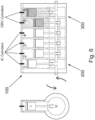
- Fully Variable Value Actuation (FVVA) as shown in Figure 5 may be used as ORC Fluid inlet and outlet ports/valves.
- the old injector opening may be modified to house a pressure and heat sensor to measure the pressure and heat of the ORC fluid inside the cylinder.
- Standard pistons are operational for ORC but preferably the ORC section piston will be concave.
- heated ORC Fluid is collected and held in a High pressure tank until injected into an ORC section cylinder via Standard fully variable valve(s), depending on application up to two per ORC cylinder. Once injected the ORC fluid expands exerting power on the piston driving it down the cylinder to BDC. The action of crankshaft and Con-rod will then drive the piston back to TDC. The spent or semi-spent ORC fluid, dependent upon residual heat and pressure may then be injected into a second ORC Cylinder. This process will continue between the two ORC cylinders until all useful energy has been used. The ORC fluid is then returned to the condenser via the outlet valve(s).
- the ORC pistons are arranged to be one at Top Dead Centre TDC and the other at Bottom Dead Centre BDC. This is so that maximum work is extracted from an ORC expansion from TDC to BDC in a first piston downstroke, and the other piston is at the opposite peak, so that in a transfer of fluid between cylinders maximum work is extracted.
- the cylinder block of an IC engine is maintained at below 70 degree Celsius at normal operating conditions - i.e. the resultant expansion of the fluid as the downstroke of the piston increases the volume and reduces the pressure in the first cylinder.
- This expansion is endothermic.
- work is done by the ORC on the first piston.
- the slightly reduced pressure ORC fluid is transferred to the adjacent second cylinder.
- the ORC fluid is still above a set pressure and temperature threshold, it is transferred back to the first cylinder. If the fluid is below the thresholds it is ejected into a condenser and the inlet valve of the first piston opens to receive the new ORC fluid to extract more work.
- a divert valve directs the fluid to the condenser.
- a controller may actuate a three way valve and based on the remaining pressure of the ORC fluid. i.e. to either dump to condenser and re-charge high pressure ORC to the first cylinder.
- the fully independent variable valve system permits this flexibility. The process is iterative.
- the ORC section heats a suitable ORC organic fluid such as ethanol or methanol or a 'hybrid' alternative.
- a suitable ORC organic fluid such as ethanol or methanol or a 'hybrid' alternative.
- ethanol at normal temperature and pressure, NTP, temperature of 20°C and an absolute pressure of 1 atm (101.325 kPa) the boiling point of ethanol is circa 70°C.
- the cylinder block temperatures will be +/- 70 °C. Thus a significant endothermic reaction is expected. This will optimise the potential for mechanical work and the spent ORC fluid to become close to its liquid state on return to condenser.
- the maximum temperature of the ORC system is estimated at +/- 500°C, dependant on application and power output.
- lateral action hydro or pneumatic spring design inlet and exhaust valves allow for a valve chest encompassing a final ORC exhaust valve to complete the ORC cycle.
- Up to 2 valves per ORC cylinder may be used dependent upon application. These may be horizontal, lateral, action.
- the condition of the ORC fluid will determine the number of ORC expansions possible (transfer of fluid from one cylinder to the other).
- electro-mechanical valves may also be employed.
- All cylinders, both ICE and ORC are preferably wet lined to enable flexible control of cylinder cubic capacity.
- the proposed invention has a potential MBHP efficiency within a range of 64% to 72%. There will be virtually zero particulate emissions. NOx emission levels will be negligible. There will be zero carbon monoxide and zero carbon dioxide emissions. Ozone depleting emissions will be below or close to below measurable levels. Only insignificant emissions are expected from lubrication oil.
- the proposed power system can be manufactured at a lesser cost than fuel cells, and the efficiency will be similar or better than current fuel cell systems;
- the proposed power system can be manufactured at a lesser cost than large battery systems. Life cycle maintenance costs will be less than either alternative and reuse/recycling will be at significantly lower cost. Furthermore, the proposed invention will aid in the recycling and refurbishing of engine blocks, which will then be able to produce cleaner power and drive an electric generator, a truck, a vehicle, a marine vessel etc.
- the mono-block may be a new bespoke mono-block or it is a repurposed standard IC engine block, wherein a number of the cylinders and pistons are left intact for IC operations and the remaining cylinders and pistons are arranged to be driven by the ORC fluid inside the ORC section cylinders.
- the Organic Rankine Cycle may recover heat from one or a combination of the engine mono-block, exhaust heat and/or engine cooling system.
- the Organic Rankine Cycle recovery utilises one organic ORC fluid, or two organic ORC fluids with two different temperature operating ranges, or a single hybrid ORC fluid arranged to operate with two or more different temperature operating ranges; when utilising a hybrid or two ORC fluids arranged to operate with two or more different temperature operating ranges, a first range is configured to operate from engine heat recovered from high temperatures such as exhaust heat, and a second range is configured to operate from engine heat recovered from coolant and general scavenging heat recovery.
- a minute quantity of Hydrogen is injected into a spark assist system, preferably a Mahler TM system, within a compression ignition engine.
- Hydrogen fuel is injected at high pressure dependent upon power need (i.e. lean or stochiometric) from 3,000,000 to 10,000,000 Pascals.
- the Hydrogen injectors may be singular, but in a preferred embodiment the Hydrogen injectors may be bifurcated to maximise mixing of Hydrogen with charge air gases, as shown in Figure 11 .
- the combined Hydrogen and Water injection into the Cylinder head is a unique configuration.
- the Hydrogen injection profile may be a standard singly form injector or preferably a Bifurcated injector.
- the purpose of bifurcation of the hydrogen injectors is to optimise a rapid disbursement of the charge air and hydrogen to effect a homogenous combustible mixture in the cylinders.
- Valve seat will need machined to accommodate valves and will require specialised metal coating.
- Dependent upon application either one or two inlet valves and one or two exhaust valves will be incorporated to each cylinder.
- the cylinder head and valve gear will be modified.
- the valve seats for both IC and ORC cylinders will need to be modified to accept a fully variable fuel and fully variable ORC fluid injection and exhaust valves and actuators.
- the modification will facilitate the fitting of fully-variable horizontal valves FVVA as the one shown in Figure 5 as opposed to the standard vertical (poppet) valves.
- Block & Sump Positively vented sump to CA intake; Positive sump pressure monitoring to SSSI/ECU; and externally insulated cylinder block as far as is practicable.
Landscapes
- Engineering & Computer Science (AREA)
- Chemical & Material Sciences (AREA)
- Combustion & Propulsion (AREA)
- Mechanical Engineering (AREA)
- General Engineering & Computer Science (AREA)
- Engine Equipment That Uses Special Cycles (AREA)
Description
- The invention describes apparatus, system and method for generating power, utilising a novel mono-block reciprocating piston engine with reduced or zero harmful emissions. The mono-block comprises a composite Internal Combustion IC section and Organic Rankine Cycle ORC section, each section displacing one or more section respective pistons, and all of the pistons connect to and drive a common crank shaft of the mono-block power plant, which may be coupled to one or more electric generators.
- Internal Combustion Engines ICE are intrinsically inefficient. Current ICE struggle to achieve 20%-35% efficiency. Most of the energy produced from the combustion of the ICE fuel is lost as heat.
-
EP2513433 describes an internal combustion engine arrangement comprising: an engine having at least one internal combustion cylinder where a piston is connected to an engine crankshaft, an intake line, a fuel injection system, an exhaust gas line, a closed Rankine circuit having an expander, characterized in that the engine further comprises at least one hybrid cylinder which is connected to the said intake line, to the said fuel injection system and to the said exhaust gas system and is further connected to the closed Rankine circuit to act as the expander of the Rankine circuit. - This invention proposes a hybrid composite engine of internal combustion IC section and Organic Rankine Cycle ORC section, with a solution that captures the lost heat of the IC engine and converts it in the ORC section into additional mechanical energy for the engine and subsequently into electrical energy.
- Furthermore, the invention utilises hydrogen as the IC fuel in order to facilitate the target of 'carbon neutral by 2050'.
- The invention addresses the present high initial and life cycle costs of battery and fuel cell alternatives whilst providing extremely high efficiencies and by utilising familiar technology, overcomes the substantial costs associated with re-tooling, retraining and maintenance.
- The invention will now be described by way of example only with reference to the accompanying drawings in which:
-
Figure 1 illustrates an overview schematic of an example system of a mono-block composite with IC and ORC sections in the same mono-block, in accordance with the invention; -
Figure 2 illustrates a typical IC Engine block that may be used to achieve the invention; -
Figure 3 illustrates a typical Crankshaft with Con-rods and with IC and ORC Pistons, wherein each end of the crankshaft is coupled to an electric generator, in accordance with the invention; -
Figure 4 illustrates schematics of pistons and cylinder chambers; whereinFig 4a illustrates an IC piston, cylinder chamber and valves; andFigure 4b illustrates an ORC piston, cylinder ORC expansion chamber, ORC fluid inlet and outlet, and in-cylinder pressure and temperature sensors; -
Figure 5 illustrates a Fully Variable Valve Actuation (FVVA); in accordance with the invention; -
Figure 6 illustrates an example arrangement and timing cycles of the IC and ORC piston-cylinders, driving a common crankshaft, in accordance with the invention; -
Figure 7 illustrates a bespoke Inlet / Exhaust Manifold, in accordance with the invention; -
Figure 8 illustrates an Exhaust Gas Recirculation (EGR) schematic, in accordance with the invention; -
Figure 9 illustrates a detailed diagram of an embodiment of the processes and components of the IC-ORC mono-block engine in accordance with the invention, wherein the ORC inlets are in parallel and ORC fluid is injected individually to each ORC cylinder, and the ORC pistons operate in a single expansion stage: inject-expand-extract to condenser, i.e. one downward/ downstroke displacement of piston per ORC fluid injection into the ORC cylinder, and then ejection of the ORC fluid into the condenser on the upward/ upstroke displacement of the piston; -
Figure 10 illustrates a detailed diagram of another embodiment of the processes and components of the IC-ORC mono-block engine in accordance with the invention, wherein the ORC inlets are in series and/or have a top-up in parallel, wherein the ORC fluid is circulated and transferred in series between ORC cylinders so that the ORC pistons operate in multiple expansion stages per one 'fresh' ORC fluid injection: e.g. inject into cylinder 5 - displace piston 5 - eject ORC fluid and transfer to inject into cylinder 6-displace piston 6 - {transfer ORC fluid back cylinder 5 - repeat times n} - then eject to condenser, i.e. repetitive expansions in the cylinders per single ORC fluid injection into the ORC cylinders until the ORC fluid pressure and heat is deemed, by a controller, to have been spent, based on data from the pressure and temperature sensors shown inFigure 4b ; -
Figure 11 illustrates a schematic of a bifurcated Hydrogen and atomised water injections into the IC cylinders, in accordance with the invention; -
Figure 12 illustrates a diagram ofIC cylinder 4 andORC cylinder 5 with their respective input and output ports/valves, in accordance with the invention; -
Figure 13 illustrates a diagram ofORC cylinder 5 andORC cylinder 6 with their respective input and output ports/valves, as well as the ORC fluid paths in accordance with embodiment ofFigure 10 . - According to a first aspect of the invention there is provided a mono-block reciprocating piston engine power plant comprising:
- two or more cylinders each having a piston housed therein;
- an internal combustion IC section controlling the displacement of at least one of the pistons and;
- an Organic Rankine Cycle ORC section controlling the displacement of at least one of the pistons;
- wherein the IC and ORC pistons connect to and drive a common crankshaft of the mono-block engine power plant; and
- wherein the Organic Rankine Cycle operates by the heat generated by the combustion in the internal combustion section, and the displacement of the pistons in the ORC section is achieved by injecting heated and pressurised ORC fluid;
- characterised in that the heated and pressurised ORC fluid is injected from a high pressure tank into a first ORC section cylinder causing downward displacement of a first piston therein;
- on the upward displacement of the first piston the ORC fluid is ejected from the first cylinder:
- wherein if the ORC fluid pressure and heat have decreased below predefined first thresholds, the ORC fluid is deemed a spent-fluid and is ejected into a condenser to be recirculated in the ORC cycle;
- if not, then the ORC fluid is transferred and injected into a second ORC section cylinder causing downward displacement of a second piston therein;
- wherein the ORC fluid is thus continuously circulated between the ORC section cylinders until deemed spent; and
wherein when the spent ORC fluid is ejected into the condenser it is replaced with heated and pressurised ORC fluid injected into one of the cylinders from the high pressure tank. - According to a second aspect of the invention there is provided a mono-block reciprocating piston engine power plant comprising:
- two or more cylinders each having a piston housed therein;
- an internal combustion IC section controlling the displacement of at least one of the pistons and;
- an Organic Rankine Cycle ORC section controlling the displacement of at least one of the pistons;
- wherein the IC and ORC pistons connect to and drive a common crankshaft of the mono-block engine power plant; and
- wherein the Organic Rankine Cycle operates by the heat generated by the combustion in the internal combustion section, and the displacement of the pistons in the ORC section is achieved by injecting heated and pressurised ORC fluid;
- characterised in that the heated and pressurised ORC fluid is injected from a high pressure tank into a first ORC section cylinder causing downward displacement of a first piston therein;
- on the upward displacement of the first piston the ORC fluid is ejected from the first cylinder:
- wherein if the ORC fluid pressure and heat are above predefined second thresholds, the ORC fluid is transferred and injected into a second ORC section cylinder causing downward displacement of a second piston therein;
- if not, then part of the ORC fluid is ejected into a condenser, to be recirculated in the ORC cycle, and the part is replaced with heated and pressurised ORC fluid from the high pressure tank;
- the resulting mixed ORC fluid is then injected into a second ORC section cylinder causing downward displacement of a second piston therein; and
- wherein the ORC fluid is thus continuously mixed and recirculated between the ORC section cylinders.
- Preferably, the mono-block engine is coupled to one or more electric generators.
- Preferably, the one or more electric generators are arranged to charge a rechargeable battery pack or a supercapacitor pack.
- Preferably, the one or more electric generators are arranged to crank the engine for it to start, i.e. act as starter motor(s) to the mono-block engine.
- Preferably, the shaft of the one or more generators is coupled in line with the crankshaft of the engine, so that the crankshaft and the generator shaft extend in the same virtual linear axis running across the length of the crankshaft.
- Preferably, at least one end of the crankshaft is coupled to one or more electric generators.
- Preferably the one or more electric generators coupled to the at least one end of the crankshaft are arranged to achieve dynamic balancing of the crankshaft.
- Preferably the mono-block is a new bespoke mono-block or it is a repurposed standard IC engine block, wherein a number of the cylinders and pistons are left intact for IC operations and the remaining cylinders and pistons are arranged to be driven by the ORC fluid inside the ORC section cylinders.
- Preferably the Organic Rankine Cycle recovers heat from one or a combination of the engine mono-block, exhaust heat and/or engine cooling system.
- Preferably the Organic Rankine Cycle recovery utilises one organic ORC fluid, or two organic ORC fluids with two different temperature operating ranges, or a single hybrid ORC fluid arranged to operate with two or more different temperature operating ranges.
- Preferably when utilising a hybrid or two ORC fluids arranged to operate with two or more different temperature operating ranges, a first range is configured to operate from engine heat recovered from high temperatures such as exhaust heat, and a second range is configured to operate from engine heat recovered from coolant and scavenging heat recovery.
- Preferably the cylinders are wet lined to enable flexible control of cylinder cubic capacity.
- Preferably filtrated water, from EGR, is injected into an IC cylinder head at a point immediately prior to the combustion temperature within the cylinder reaching a point where NOx will be formed; and
the injected water is timed to reach the peak IC cylinder temperature zone immediately prior to NOx threshold temperature being reached. - According to a third aspect of the invention there is provided a system for generating electricity utilising the above mentioned engines.
- According to a fourth aspect of the invention there is provided a method for generating electricity utilising the above mentioned engines.
- The invention describes an apparatus, system and method for generating power utilising a novel design for a mono-block reciprocating piston engine with reduced or zero harmful emissions. The mono-block comprises a composite internal combustion IC section and an Organic Rankine Cycle ORC section, each section displacing one or more section respective pistons, and all of the pistons connect to and drive a common crank shaft of the mono-block power plant.
- In this description the mono-block may be interchangeably referred to as a common-block or the engine block, or simply the block.
- The internal combustion engine ICE component of the block may utilise any combustible fuel known in the art, such as petrol, diesel, etc, as well as gaseous fluids such as methane, butane or propane. However, to reduce or avoid resultant carbon emissions the use of cleaner combustible fuels, such as hydrogen is preferred.
- In this description, the one or more pistons and cylinders of the ICE section will be referred to as ICE-piston(s) and ICE-cylinder(s).
- In the Organic Rankine Cycle ORC section, the one or more pistons and cylinders will be referred to as ORC-piston(s) and ORC-cylinder(s). The one or more ORC-pistons are driven by an internal ORC cycle that to operate utilises the heat generated by the combustion in the internal combustion section of the engine.
- All high grade 'waste' heat from the engine is recovered using counter-current heat exchangers. The ORC section heats a suitable ORC organic fluid such as ethanol or methanol or a 'hybrid' alternative.
- The IC section and the ORC section generate power to displace their respective IC and ORC pistons independently of each other. However, as the IC and ORC pistons are connected to and drive a common crankshaft, their firing and displacement timing is synchronised to achieve maximum energy transfer from piston displacement to crankshaft rotation, and thus maximum extracted work.
Figure 3 shows acrankshaft 110 connected to IC and ORC pistons. - In one embodiment, the mono-block engine is coupled to one or more electric generators. At least one end of the crankshaft is coupled to one or more electric generators. The coupling is so that the shaft of the one or more generators is coupled/ connected to the crankshaft of the mono-block, either directly or via gear arrangements. The coupling can be at the ends of the shaft and the crankshaft. The one or more electric generators is connected to and arranged to charge a rechargeable battery pack or a supercapacitor pack.
- The shaft of the one or more generators is coupled in line with the crankshaft of the engine, so that the crankshaft and the generator shaft extend in the same virtual linear axis running across the length of the crankshaft. When more then one generators are connected they may be coupled in series in line in the same virtual linear axis, forming one long continuous joint-shaft. Electro-mechanical clutches may be employed to couple or de-couple generators from the continuous joint-shaft.
-
Figure 3 shows acrankshaft 110 which may be coupled to at least onegenerator - Alternatively, the crankshaft and the generator shaft may be coupled by gears in various angular or parallel arrangements.
- The one or more electric generators rechargeable battery pack or a supercapacitor pack are arranged to drive an electric motor.
- In a further embodiment, the electric generator may be arranged to crank the engine for it to start, i.e. act as starter motor(s) to the mono-block engine. One or more of the motor generators may be used as a starter motor to crank the engine on start-up. To initiate ignition (if more than one motor-generators are installed) an e.g. via an electronic clutch may be used to decouple all the generators that are not required for the engine start-up process.
- The one or more electric generators coupled at least one end of the crankshaft are arranged to achieve dynamic balancing of the crankshaft.
- The electric generators may be situated at front or rear power take-offs from the crankshaft.
- The design of the motor-generator(s) is preferably oil-cooled pancake design with high high-grade heat recovered to the ORC process or switched reluctance design.
- Engine load and power generation may be controlled by switching off or mechanically decoupling one or more generators as required, e.g. via an electronic clutch.
- Motor generators will effect regenerative braking with energy recovered being stored in the ultra/super capacitor or battery packs.
- Depending on the work and load requirements the IC and ORC sections may be operating simultaneously or each section may be turned off separately. As an example, the IC section is operational and the ORC section may be turned off until the engine and the ORC subsystem reach the required ORC operating temperatures. Likewise, the IC section may be turned off and the ORC section will continue to operate the crankshaft and charge the battery bank until all heat has been scavenged from the engine and all the heat has been depleted in the ORC fluid and ORC section.
- Because the IC and ORC sections are in the same engine block a combination of IC and ORC cylinder numbers may be configured depending on the type of engine and work required.
- The invention works with a new customised mono-block as well as repurposing and modifying a standard ICE engine block, wherein a number of the cylinders and pistons is left untouched for IC operations and the remaining cylinders and pistons are arranged to be driven by the ORC subsystem.
- The principles of the proposed invention are applicable to any engine block with two or more cylinders, and in various alignments, such as inline, V-shape, W-shape, boxer, linear etc. The proposed mono-block may be utilised for vehicle engines, truck engines, large marine, static and rail power plant etc.
- To better describe the invention, an example employing a 6 cylinder block, as shown in
Figure 2 , will be described. - Referring to
Figure 1 , the block ofFigure 2 has been modified so thatcylinders 1 to 4 are kept as IC cylinders andcylinders Figures 3 ,9 ,10 and 14. - The IC and ORC cylinders have been shown in this arrangement as an example and for ease of referencing in order to convey the invention. Other arrangements are possible, wherein the IC cylinders may be in front of the ORC cylinders, or the IC and ORC cylinders are evenly or unevenly reciprocated.
- In some embodiments, in order to increase the heat extraction from the engine the ORC cylinders are arranged to preferably be close to the water, coolant pump.
- Referring to
Figure 1 , the mono-block 100 comprises anIC section 200 and anORC section 300. For the purpose of this example, the block comprisescylinders cylinders piston 1,piston 2 and so on. -
Figure 2 illustrates a typicalIC Engine block 100 that may be used to achieve the invention, andFigure 3 shows thecrankshaft 110 of the engine. - Referring to
Figures 9 and10 , the invention proposes a mono-block reciprocating piston engine power plant comprising two or more cylinders each having a piston housed therein (an example with 6 cylinders: 1, 2, 3, 4, 5 and 6) is shown, whereincylinders 1 to 4 are IC section cylinders andcylinders - an internal
combustion IC section 200 controls the displacement of at least one of thepistons 1 to 4 and; an Organic Rankine Cycle ORC section controls the displacement of at least one of thepistons common crankshaft 110 of the mono-blockengine power plant 100; and - wherein the Organic Rankine Cycle operates by the heat generated by the combustion in the internal combustion section, and the displacement of the pistons in the ORC section is achieved by injecting heated and pressurised ORC fluid.
- Looking at the
IC section 200, combustion fuel such as Hydrogen H2 is injected into thecylinders 1 to 4. Atomised water (more detail below and inFigure 11 ) is also injected in the IC cylinders. - Heat Recovery - Heat is recovered from the IC section of the engine from the exhaust and EGR and from the engine cooling system, as well as scavenged heat.
- The recovered heat is used to operate an Organic Rankine Cycle ORC. Referring to
Figures 9 and10 , heated ORC fluid from the Heat Recovery is collected in an High Pressure Tank. Heated and pressurised ORC fluid is then injected into the ORC section cylinders (5 and 6). The ORC fluid is injected to the cylinder (s) whose piston is at the Top Dead Centre and the injected ORC fluid causes a full downward displacement of the piston therein. -
Figure 9 illustrates a detailed diagram of an embodiment of the processes and components of the IC-ORC mono-block engine in accordance with the invention, wherein the ORC inlets are in parallel and ORC fluid is injected individually to each ORC cylinder, and the ORC pistons operate in a single expansion stage: inject-expand-extract to condenser, i.e. one downward/ downstroke displacement of piston per ORC fluid injection into the ORC cylinder, and then ejection of the ORC fluid into the condenser on the upward/ upstroke displacement of the piston. - Therefore, in one embodiment heated and pressurised ORC fluid is injected from a high pressure tank into an ORC section cylinder causing downward displacement of the piston therein, and on the upward displacement of the piston the ORC fluid is ejected into a condenser, to be recirculated in the ORC cycle. The inlets of
cylinder Figure 7 ) and the Heat Recovery, and then feed back into the High Pressure Tank and so on. -
Figure 10 illustrates a detailed diagram of another embodiment of the processes and components of the IC-ORC mono-block engine in accordance with the invention, wherein the ORC inlets are in series and/or have a top-up in parallel, wherein the ORC fluid is circulated and transferred in series between ORC cylinders so that the ORC pistons operate in multiple expansion stages per one 'fresh' ORC fluid injection: e.g. inject into cylinder 5 - displace piston 5 - eject ORC fluid and transfer to inject into cylinder 6-displace piston 6 - {transfer ORC fluid back cylinder 5 - repeat times n} - then eject to condenser, i.e. repetitive expansions in the cylinders per single ORC fluid injection into the ORC cylinders until the ORC fluid pressure and heat is deemed, by a controller, to have been spent, based on data from the pressure and temperature sensors shown inFigure 4b . - Referring to
Figure 10 , the ORC cycle in the ORC cylinders can be according one of the two embodiments below:
Heated and pressurised ORC fluid is injected from the high pressure tank into a first ORC section cylinder (5) causing downward displacement of a first piston therein (piston 5) ; on the upward displacement of the first piston (5) the ORC fluid is ejected from the first cylinder (5): wherein if the ORC fluid pressure and heat have decreased below predefined first thresholds, the ORC fluid is deemed a spent-fluid and is ejected into a condenser to be recirculated in the ORC cycle; if not, then the ORC fluid is transferred and injected into a second ORC section cylinder (6) causing downward displacement of a second piston (6) therein; wherein the ORC fluid is thus continuously circulated between the ORC section cylinders ( 5 to 6 to 5 to...) until deemed spent; and wherein when the spent ORC fluid is ejected into the condenser it is replaced with heated and pressurised ORC fluid injected into one of the cylinders from the high pressure tank. - A controller acquires the pressure and heat data from the heat and pressure sensors (see
Figure 4b ) and controls the flow of the ORC fluid to either the next cylinder in the process or to the condenser. - In another embodiment the heated and pressurised ORC fluid is injected from the high pressure tank into a first
ORC section cylinder 5 causing downward displacement of afirst piston 5 therein; on the upward displacement of thefirst piston 5 the ORC fluid is ejected from the first cylinder: wherein if the ORC fluid pressure and heat are above predefined second thresholds, the ORC fluid is transferred and injected into a secondORC section cylinder 6 causing downward displacement of a second piston therein 6; if not, then part of the ORC fluid is ejected into the condenser, to be recirculated in the ORC cycle, and the part is replaced with heated and pressurised ORC fluid from the high pressure tank; the resulting mixed ORC fluid is then injected into the secondORC section cylinder 6 causing downward displacement of asecond piston 6 therein; and wherein the ORC fluid is thus continuously mixed and recirculated between the ORC section cylinders. -
Figure 12 shows a schematics of the inlets and outlets of an IC cylinder and an ORC cylinder. More specifically, in theIC section 200 is shownIC cylinder 4 with combustion fuel injector-inlet valve together referenced as 241, and atomisedwater injection valve 240, andexhaust valves 244. - In the
ORC section 300 is shownORC cylinder 5 with ORCfluid inlet valves 351, circulation outlet fluid valve to next ORC cylinder 353 (e.g. when ORC fluid is transferred to ORC cylinder 6), and outletfluid valve 354 to condenser. -
Figure 13 shows a schematics of the inlets and outlets of twoORC cylinders ORC section 300, as well as the ORC fluid paths in accordance with embodiment ofFigure 10 . -
Cylinder 5 comprises ORCfluid inlet valves 351, andcylinder 6 comprises ORCfluid inlet valves 361, both of which may receive ORC fluid from the High Pressure Tank and/or the circulation ORC fluid valve/outlet of another ORC cylinder. E.g. circulation outlet fluid valve tonext ORC cylinder 363 ofcylinder 6 transfers ORC fluid intocylinder 5. E.g. circulation outlet fluid valve tonext ORC cylinder 353 ofcylinder 5 transfers ORC fluid intocylinder 6. If more then two ORC cylinders are available then the circulation of fluid is controlled by a ORC circulation fluid controller and is also dependent on the stroke cycle of the ORC cylinders. -
Figure 13 further shows the outlet fluid valve tocondenser 354 ofcylinder 5 and outlet fluid valve tocondenser 364 ofcylinder 6, are further shown. - Referring to
Figure 4 , the ORC modified cylinder will keep the same configuration as per IC cylinders. The cylinder head might change to accommodate the changes. The IC fuel inlet valve is modified to become the ORC fluid inlet; the IC exhaust valve becomes an ORC fluid outlet. Fully Variable Value Actuation (FVVA) as shown inFigure 5 may be used as ORC Fluid inlet and outlet ports/valves. - The old injector opening may be modified to house a pressure and heat sensor to measure the pressure and heat of the ORC fluid inside the cylinder. Standard pistons are operational for ORC but preferably the ORC section piston will be concave.
- As shown in
Figure 10 and11 , heated ORC Fluid is collected and held in a High pressure tank until injected into an ORC section cylinder via Standard fully variable valve(s), depending on application up to two per ORC cylinder. Once injected the ORC fluid expands exerting power on the piston driving it down the cylinder to BDC. The action of crankshaft and Con-rod will then drive the piston back to TDC. The spent or semi-spent ORC fluid, dependent upon residual heat and pressure may then be injected into a second ORC Cylinder. This process will continue between the two ORC cylinders until all useful energy has been used. The ORC fluid is then returned to the condenser via the outlet valve(s). - Referring to
Figure 3 andFigure 6 , the ORC pistons are arranged to be one at Top Dead Centre TDC and the other at Bottom Dead Centre BDC. This is so that maximum work is extracted from an ORC expansion from TDC to BDC in a first piston downstroke, and the other piston is at the opposite peak, so that in a transfer of fluid between cylinders maximum work is extracted. - As an example, the cylinder block of an IC engine is maintained at below 70 degree Celsius at normal operating conditions - i.e. the resultant expansion of the fluid as the downstroke of the piston increases the volume and reduces the pressure in the first cylinder. This expansion is endothermic. Thus, work is done by the ORC on the first piston. On the upstroke of the first piston, the slightly reduced pressure ORC fluid is transferred to the adjacent second cylinder. On the downstroke of the second piston if the ORC fluid is still above a set pressure and temperature threshold, it is transferred back to the first cylinder. If the fluid is below the thresholds it is ejected into a condenser and the inlet valve of the first piston opens to receive the new ORC fluid to extract more work. When all useful mechanical work is extracted, a divert valve directs the fluid to the condenser. A controller may actuate a three way valve and based on the remaining pressure of the ORC fluid. i.e. to either dump to condenser and re-charge high pressure ORC to the first cylinder. The fully independent variable valve system permits this flexibility. The process is iterative.
- The ORC section heats a suitable ORC organic fluid such as ethanol or methanol or a 'hybrid' alternative. As an example when using ethanol, at normal temperature and pressure, NTP, temperature of 20°C and an absolute pressure of 1 atm (101.325 kPa) the boiling point of ethanol is circa 70°C. The cylinder block temperatures will be +/- 70 °C. Thus a significant endothermic reaction is expected. This will optimise the potential for mechanical work and the spent ORC fluid to become close to its liquid state on return to condenser. The maximum temperature of the ORC system is estimated at +/- 500°C, dependant on application and power output.
- In one embodiment, lateral action hydro or pneumatic spring design inlet and exhaust valves allow for a valve chest encompassing a final ORC exhaust valve to complete the ORC cycle. Up to 2 valves per ORC cylinder may be used dependent upon application. These may be horizontal, lateral, action. The condition of the ORC fluid will determine the number of ORC expansions possible (transfer of fluid from one cylinder to the other). In other embodiments electro-mechanical valves may also be employed.
- All cylinders, both ICE and ORC are preferably wet lined to enable flexible control of cylinder cubic capacity.
- The mechanical architecture with the IC cylinders and use of cylinders as ORC expanders within same mono-block is unique.
- Efficiency is optimised through incorporating the following:
- Maintaining steady state power unit Revolution Per Minute by connecting the crankshaft directly to one or more preferably pancake design ECDC motor/generators. Other means of electrical or shaft power generation could be applicable;
- 'Splitting' the cylinder block into a four 'combustion cylinder', four stroke configuration, with the remaining two cylinders powered by a 'two stroke acting' organic Rankine cycle design, utilising all sensible heat, recovered from subsystems and exhaust gases. Preferably the ORC fluid will be methanol or ethanol but other low or zero ozone depleting alternatives may be employed;
- The 'ORC cylinders may operate as single stage, two stage or three stage expanders, dependant on the temperature/pressure condition of the ORC fluid. This being achieved by fast acting multi-way (preferably) inlet and exhaust valves operating across the two cylinders and the organic fluid exhaust;
- In the example of a six-cylinder block, with a 'firing order of 1-5-3-6-2-4,
cylinders cylinders - Preferably, PEM technology shall be incorporated in the combustion air inlet to enrich the oxygen supply to the ICE unit to reduce inert NOx gases.
- A surge battery system will harvest excess power, e.g. regenerative braking in automotive applications, surplus generating capacity and thereby stored to meet high load conditions e.g. hill climb and initial start conditions;
- The four combustion cylinders shall have the following features:
- ∘ Spark assisted compression ignition system, preferably Mahler type;
- ∘ Fully variable independently controlled inlet and exhaust valves to facilitate variable compression and also avoid unnecessary 'pumping losses;
- ∘ Preferably, turbo-charging or super charging, to increase the induction charge;
- ∘ The application of manifold water injection (inter cooler effect) together with direct (in cylinder) water injection, (harvested from condensed filtered water from the exhaust gases) to effect induction cooling, avoid cylinder hotspots, create highly turbulent fuel air mixing; minimise NOx formation through controlling maximum combustion gas temperatures and create flash steam to increase cylinder power output, as shown in
Figure 7 ; - ∘ The application of aggressive ignition timing to optimise efficiency and power;
- ∘ The ability to 'switch out' an individual cylinder when the power is not required, reducing pumping losses;
- ∘ The avoidance of the power losses associated with a camshaft drive system; separate starter motor, separate alternator, high pressure fuel pump (as in diesel) and minimised radiator fan cooling power requirements.
- The engine uses a temperature and volume control of exhaust gas recirculation (EGR), as shown in
Figure 8 This will prevent pre-ignition and 'hot spot' pre combustion and it is anticipated that since the EGR gases will be partially pre-cooled, overall combustion efficiency of the ICE unit will be increased, whilst ensuring near zero NOx emissions. - Using Hydrogen as fuel in addition to the other auxiliary methods, the proposed invention has a potential MBHP efficiency within a range of 64% to 72%. There will be virtually zero particulate emissions. NOx emission levels will be negligible. There will be zero carbon monoxide and zero carbon dioxide emissions. Ozone depleting emissions will be below or close to below measurable levels. Only insignificant emissions are expected from lubrication oil.
- The proposed power system can be manufactured at a lesser cost than fuel cells, and the efficiency will be similar or better than current fuel cell systems;
- The proposed power system can be manufactured at a lesser cost than large battery systems. Life cycle maintenance costs will be less than either alternative and reuse/recycling will be at significantly lower cost. Furthermore, the proposed invention will aid in the recycling and refurbishing of engine blocks, which will then be able to produce cleaner power and drive an electric generator, a truck, a vehicle, a marine vessel etc.
- The mono-block may be a new bespoke mono-block or it is a repurposed standard IC engine block, wherein a number of the cylinders and pistons are left intact for IC operations and the remaining cylinders and pistons are arranged to be driven by the ORC fluid inside the ORC section cylinders.
- The Organic Rankine Cycle may recover heat from one or a combination of the engine mono-block, exhaust heat and/or engine cooling system. The Organic Rankine Cycle recovery utilises one organic ORC fluid, or two organic ORC fluids with two different temperature operating ranges, or a single hybrid ORC fluid arranged to operate with two or more different temperature operating ranges; when utilising a hybrid or two ORC fluids arranged to operate with two or more different temperature operating ranges, a first range is configured to operate from engine heat recovered from high temperatures such as exhaust heat, and a second range is configured to operate from engine heat recovered from coolant and general scavenging heat recovery.
- Further details on the processes of the engine are provided below.
- In one preferred embodiment wherein the IC section uses Hydrogen as fuel, the features below may be further used.
- A minute quantity of Hydrogen is injected into a spark assist system, preferably a Mahler™ system, within a compression ignition engine.
- Hydrogen fuel is injected at high pressure dependent upon power need (i.e. lean or stochiometric) from 3,000,000 to 10,000,000 Pascals.
- The Hydrogen injectors may be singular, but in a preferred embodiment the Hydrogen injectors may be bifurcated to maximise mixing of Hydrogen with charge air gases, as shown in
Figure 11 . - A greater range of injection pressures determined by opening and closing of the Hydrogen supply valve. Timing control is determined by power demand via ECU.
- Power needs are dictated by the ECU. Likewise Exhaust Gas temperature monitoring is done via SSSI/ECU:
- i) Ultra-filtrated water (from EGR) is injected into cylinder head at a point immediately prior to the combustion temperature within the cylinder reaching a point where NOx will be formed, as shown in
Figure 11 . - ii) Atomised water injection is via two ultra-fine jets at an angle of between 5 and 12 degrees, as shown in
Figure 11 , dependent upon cylinder diameter and stroke - iii) Water injection prevents risk of 'hot-spotting' within the cylinder and exhaust valve to avoid pre-ignition.
- iv) This process will facilitate the 'flash-steam' process increasing power output from each ICE cylinder.
- v) Injected water will be timed to reach the peak ICE cylinder temperature zone immediately prior to NOx threshold temperature is reached.
- The integration of water injection, flash steam and advanced combustion control within a Hydrogen fuelled engine is unknown in the art
- The combined Hydrogen and Water injection into the Cylinder head is a unique configuration.
- Referring again to
Figure 11 , the Hydrogen injection profile may be a standard singly form injector or preferably a Bifurcated injector. The purpose of bifurcation of the hydrogen injectors is to optimise a rapid disbursement of the charge air and hydrogen to effect a homogenous combustible mixture in the cylinders. - An existing engine block, conrod, crankshaft, piston design and lubrication are modified as set out below:
- Strengthened con rods;
- Avoidance of incompatible metals;
- Strengthened Crankshaft (if required);
- ORC piston rings fabricated from PTFE or similar compound;
- The inclusion of WS2 and MS2 solid lubricants into the engine oil (reduced wear and lower friction losses) to address particularly the effect of a 'dry' fuel;
- Modified pistons as/if required;
- A re-designed cylinder head to accommodate the changes to the design of fully independent variable valves and actuators;
- Pistons are preferably concave.
- When repurposing and modifying a standard ICE engine block the Head requires some modifications as noted below:
Valve seat will need machined to accommodate valves and will require specialised metal coating. Dependent upon application either one or two inlet valves and one or two exhaust valves will be incorporated to each cylinder. - The cylinder head and valve gear will be modified. The valve seats for both IC and ORC cylinders will need to be modified to accept a fully variable fuel and fully variable ORC fluid injection and exhaust valves and actuators.
- The modification will facilitate the fitting of fully-variable horizontal valves FVVA as the one shown in
Figure 5 as opposed to the standard vertical (poppet) valves. - Block & Sump - Positively vented sump to CA intake; Positive sump pressure monitoring to SSSI/ECU; and externally insulated cylinder block as far as is practicable.
- Exhaust Manifold - Twin skinned construction to retain heat and insulated between skins; Exhaust gas temperature monitored for water injection process, as shown in
Figure 7 . - Crank Shaft - Metallurgical hardening and coating of the crankshaft will be required under some conditions dependent on maximum power output; Crankshaft will be machined to allow front and rear power take-off; Crankshaft bearings will be of a material that resists degradation from any Hydrogen that may be present within the bottom of the block.
- Con Rods - Will be metallurgically treated and strengthened to withstand Hydrogen fuel and greater power transfer; Con Rod bearings will be of a material that resists degradation from any Hydrogen that may be present within the bottom of the block.
Claims (15)
- A mono-block reciprocating piston engine power plant (100) comprising:two or more cylinders each having a piston housed therein;an internal combustion IC section (200) controlling the displacement of at least one of the pistons and;an Organic Rankine Cycle ORC section (300) controlling the displacement of at least one of the pistons;wherein the IC and ORC pistons connect to and drive a common crankshaft (110) of the mono-block engine power plant (100); andwherein the Organic Rankine Cycle operates by the heat generated by the combustion in the internal combustion section, and the displacement of the pistons in the ORC section is achieved by injecting heated and pressurised ORC fluid;characterised in that the heated and pressurised ORC fluid is injected from a high pressure tank into a first ORC section cylinder causing downward displacement of a first piston therein;on the upward displacement of the first piston the ORC fluid is ejected from the first cylinder:wherein if the ORC fluid pressure and heat have decreased below predefined first thresholds, the ORC fluid is deemed a spent-fluid and is ejected into a condenser (354) to be recirculated in the ORC cycle;if not, then the ORC fluid is transferred and injected into a second ORC section cylinder causing downward displacement of a second piston therein; wherein the ORC fluid is thus continuously circulated between the ORC section cylinders until deemed spent; andwherein when the spent ORC fluid is ejected into the condenser it is replaced with heated and pressurised ORC fluid injected into one of the cylinders from the high pressure tank.
- A mono-block reciprocating piston engine power plant (100) comprising:two or more cylinders each having a piston housed therein;an internal combustion IC section (200) controlling the displacement of at least one of the pistons and;an Organic Rankine Cycle ORC section (300) controlling the displacement of at least one of the pistons;wherein the IC and ORC pistons connect to and drive a common crankshaft (110) of the mono-block engine power plant (100); andwherein the Organic Rankine Cycle operates by the heat generated by the combustion in the internal combustion section, and the displacement of the pistons in the ORC section is achieved by injecting heated and pressurised ORC fluid;characterised in that the heated and pressurised ORC fluid is injected from a high pressure tank into a first ORC section cylinder causing downward displacement of a first piston therein;on the upward displacement of the first piston the ORC fluid is ejected from the first cylinder:wherein if the ORC fluid pressure and heat are above predefined second thresholds, the ORC fluid is transferred and injected into a second ORC section cylinder causing downward displacement of a second piston therein;if not, then part of the ORC fluid is ejected into a condenser (354), to be recirculated in the ORC cycle, and the part is replaced with heated and pressurised ORC fluid from the high pressure tank;the resulting mixed ORC fluid is then injected into a second ORC section cylinder causing downward displacement of a second piston therein; andwherein the ORC fluid is thus continuously mixed and recirculated between the ORC section cylinders.
- The engine of claim 1 or claim 2, wherein the mono-block engine is coupled to one or more electric generators (121, 122).
- The engine of claim 3, wherein the one or more electric generators are arranged to charge a rechargeable battery pack or a supercapacitor pack.
- The engine of any one of the above claims, wherein the one or more electric generators are arranged to crank the engine for it to start, i.e. act as starter motor(s) to the mono-block engine.
- The engine of any one of the above claims, wherein the shaft of the one or more generators is coupled in line with the crankshaft of the engine, so that the crankshaft and the generator shaft extend in the same virtual linear axis running across the length of the crankshaft.
- The engine of claim 6, wherein at least one end of the crankshaft is coupled to one or more electric generators, and
wherein the one or more electric generators coupled to the at least one end of the crankshaft are arranged to achieve dynamic balancing of the crankshaft. - The engine of any one of the above claims, wherein the mono-block is a new bespoke mono-block or it is a repurposed standard IC engine block, wherein a number of the cylinders and pistons are left intact for IC operations and the remaining cylinders and pistons are arranged to be driven by the ORC fluid inside the ORC section cylinders.
- The engine of any one of the above claims, wherein the Organic Rankine Cycle recovers heat from one or a combination of the engine mono-block, exhaust heat and/or engine cooling system.
- The engine of any one of the above claims, wherein the Organic Rankine Cycle recovery utilises one organic ORC fluid, or two organic ORC fluids with two different temperature operating ranges, or a single hybrid ORC fluid arranged to operate with two or more different temperature operating ranges.
- The engine of claim 10, wherein when utilising a hybrid or two ORC fluids arranged to operate with two or more different temperature operating ranges, a first range is configured to operate from engine heat recovered from high temperatures such as exhaust heat, and a second range is configured to operate from engine heat recovered from coolant and general scavenging heat recovery.
- The engine of any one of the above claims, wherein the cylinders are wet lined to enable flexible control of cylinder cubic capacity.
- The engine of any one of the above claims, wherein filtrated water, from EGR, is injected into an IC cylinder head at a point immediately prior to the combustion temperature within the cylinder reaching a point where NOx will be formed; and
the injected water is timed to reach the peak IC cylinder temperature zone immediately prior to NOx threshold temperature being reached. - A system for generating electricity utilising the engine of claims 3 to 13.
- A method for generating electricity utilising the engine of claims 3 to 13.
Applications Claiming Priority (2)
| Application Number | Priority Date | Filing Date | Title |
|---|---|---|---|
| GBGB2013605.7A GB202013605D0 (en) | 2020-08-28 | 2020-08-28 | A mono-block reciprocating piston composite ice/orc power plant |
| PCT/EP2021/073919 WO2022043565A1 (en) | 2020-08-28 | 2021-08-30 | A mono-block reciprocating piston composite ice/orc power plant |
Publications (3)
| Publication Number | Publication Date |
|---|---|
| EP4211337A1 EP4211337A1 (en) | 2023-07-19 |
| EP4211337C0 EP4211337C0 (en) | 2025-04-09 |
| EP4211337B1 true EP4211337B1 (en) | 2025-04-09 |
Family
ID=72749780
Family Applications (1)
| Application Number | Title | Priority Date | Filing Date |
|---|---|---|---|
| EP21772734.6A Active EP4211337B1 (en) | 2020-08-28 | 2021-08-30 | A mono-block ice/orc power plant with a reciprocating piston assembly |
Country Status (7)
| Country | Link |
|---|---|
| US (1) | US11920513B2 (en) |
| EP (1) | EP4211337B1 (en) |
| JP (1) | JP7518974B2 (en) |
| KR (1) | KR20230073220A (en) |
| CN (1) | CN116368290B (en) |
| GB (2) | GB202013605D0 (en) |
| WO (1) | WO2022043565A1 (en) |
Family Cites Families (18)
| Publication number | Priority date | Publication date | Assignee | Title |
|---|---|---|---|---|
| DE2414147A1 (en) * | 1974-03-23 | 1975-10-09 | Ewald Dipl Ing Renner | Motor vehicle IC engine - has auxiliary cylinder worked by vapourised cooling fluid from main engine |
| JPS6111445Y2 (en) * | 1979-03-14 | 1986-04-11 | ||
| CN1017740B (en) * | 1987-03-30 | 1992-08-05 | 华中工学院 | Six-stroke adiabatic engine device |
| US4901531A (en) * | 1988-01-29 | 1990-02-20 | Cummins Engine Company, Inc. | Rankine-diesel integrated system |
| EP0862685A4 (en) | 1995-11-01 | 2000-04-26 | Barry Frank Hughes | Combination internal combustion and steam engine |
| EP1593820A1 (en) * | 2004-05-04 | 2005-11-09 | Uwe Hansen | Method for increasing the efficiency of all thermal engines, characterised in that the produced thermal energy is converted in to mechanical energy up to a temperature lower than 100 C. |
| AT501400A1 (en) * | 2004-12-22 | 2006-08-15 | Walter Ing Falkinger | INCREASING EFFICIENCY IN HUB PISTON ENGINES |
| CN100360773C (en) * | 2006-04-06 | 2008-01-09 | 郑哲立 | Superhigh boosting double-circulation variable discharge I.C. engine |
| KR20100014526A (en) * | 2007-03-07 | 2010-02-10 | 제임스 브이. 하몬 | Internal combustion engine with auxiliary steam power recovered from waste heat |
| US7975485B2 (en) | 2007-08-29 | 2011-07-12 | Yuanping Zhao | High efficiency integrated heat engine (HEIHE) |
| DE102008013673B3 (en) * | 2008-03-11 | 2009-09-17 | Richard Engelmann | Piston steam engine for a solar powered Rankine cycle |
| WO2010037912A2 (en) * | 2008-10-02 | 2010-04-08 | Claude Baudino | Hybrid motor system |
| US20100083919A1 (en) * | 2008-10-03 | 2010-04-08 | Gm Global Technology Operations, Inc. | Internal Combustion Engine With Integrated Waste Heat Recovery System |
| WO2011073718A2 (en) * | 2009-12-18 | 2011-06-23 | Renault Trucks | Internal combustion engine arrangement with rankine circuit and hybrid cylinder, especially for an automotive vehicle |
| DE102011117356A1 (en) | 2011-10-29 | 2013-05-02 | Wabco Gmbh | Motor coupling unit e.g. reciprocating piston machine connected with internal combustion engine, has coupling unit that couples torque transmission unit to motor, such that vapor pressure of process fluid of expander is vaporized |
| CN103758659B (en) * | 2014-01-08 | 2015-11-18 | 南京航空航天大学 | High-efficiency compact internal-combustion engine-organic Rankine bottoming cycle combined system and method for work thereof |
| CN104533604B (en) | 2014-10-31 | 2017-06-06 | 北京工业大学 | A kind of engine exhaust heat recovery system based on Piston Expander |
| CN112260316B (en) | 2020-10-20 | 2022-05-03 | 浙江大学 | Off-grid type multifunctional complementary combined cooling, heating and power and humidity system and method thereof |
-
2020
- 2020-08-28 GB GBGB2013605.7A patent/GB202013605D0/en not_active Ceased
-
2021
- 2021-08-30 CN CN202180074387.3A patent/CN116368290B/en active Active
- 2021-08-30 KR KR1020237010578A patent/KR20230073220A/en not_active Withdrawn
- 2021-08-30 JP JP2023515241A patent/JP7518974B2/en active Active
- 2021-08-30 EP EP21772734.6A patent/EP4211337B1/en active Active
- 2021-08-30 US US18/043,485 patent/US11920513B2/en active Active
- 2021-08-30 WO PCT/EP2021/073919 patent/WO2022043565A1/en not_active Ceased
- 2021-08-31 GB GB2112357.5A patent/GB2599786B/en active Active
Also Published As
| Publication number | Publication date |
|---|---|
| EP4211337C0 (en) | 2025-04-09 |
| JP7518974B2 (en) | 2024-07-18 |
| US11920513B2 (en) | 2024-03-05 |
| US20230250751A1 (en) | 2023-08-10 |
| GB2599786B (en) | 2022-08-31 |
| EP4211337A1 (en) | 2023-07-19 |
| CN116368290B (en) | 2024-08-13 |
| GB202112357D0 (en) | 2021-10-13 |
| GB2599786A (en) | 2022-04-13 |
| JP2023535651A (en) | 2023-08-18 |
| KR20230073220A (en) | 2023-05-25 |
| WO2022043565A1 (en) | 2022-03-03 |
| GB202013605D0 (en) | 2020-10-14 |
| CN116368290A (en) | 2023-06-30 |
Similar Documents
| Publication | Publication Date | Title |
|---|---|---|
| US8082892B2 (en) | High efficiency integrated heat engine-2 (HEIHE-2) | |
| US7975485B2 (en) | High efficiency integrated heat engine (HEIHE) | |
| US7958872B1 (en) | Airless engine with gas and water recycling | |
| US5339632A (en) | Method and apparatus for increasing the efficiency of internal combustion engines | |
| US8661816B2 (en) | Hybrid combustion energy conversion engines | |
| US8061140B2 (en) | High efficiency multicycle internal combustion engine with waste heat recovery | |
| Kryshtopa et al. | Fuel economy raising of alternative fuel converted diesel engine | |
| US8006654B1 (en) | High efficiency eight stroke internal combustion engine | |
| EP2609302B1 (en) | Engine arrangement comprising a heat recovery circuit | |
| US20130291826A1 (en) | Systems and vehicles incorporating improved engine cooling and energy generation | |
| WO1991010044A1 (en) | Energy conserving engine | |
| JP5721129B2 (en) | Compressed air heat engine | |
| EP4211337B1 (en) | A mono-block ice/orc power plant with a reciprocating piston assembly | |
| US8683988B2 (en) | Systems and methods for improved engine cooling and energy generation | |
| US9297337B2 (en) | Internal combustion and waste heat steam engine having a heat recovery steam generator exhaust manifold | |
| US9541027B2 (en) | System and method for recovering waste heat | |
| Matulić et al. | Thermodynamic analysis of active modular internal combustion engine concept: targeting efficiency increase and carbon dioxide emissions reduction of gasoline engines | |
| JP2012002191A (en) | Hybrid engine using the same cylinder | |
| JP5721026B2 (en) | Circulating gas hybrid engine | |
| RU2513076C1 (en) | Plunger-free engine | |
| EP4293208A1 (en) | An internal combustion engine system | |
| WO2014127146A1 (en) | Systems and methods for improved engine cooling and energy generation | |
| Marchetti et al. | A Six-Stroke, High-Efficiency Quasiturbine Concept Engine With Distinct, Thermally-Insulated Compression and Expansion Components | |
| WO2026038962A1 (en) | A system and method for controlling an internal combustion engine | |
| Agarwal | A STUDY OF SIX STROKE ENGINE |
Legal Events
| Date | Code | Title | Description |
|---|---|---|---|
| STAA | Information on the status of an ep patent application or granted ep patent |
Free format text: STATUS: UNKNOWN |
|
| STAA | Information on the status of an ep patent application or granted ep patent |
Free format text: STATUS: THE INTERNATIONAL PUBLICATION HAS BEEN MADE |
|
| PUAI | Public reference made under article 153(3) epc to a published international application that has entered the european phase |
Free format text: ORIGINAL CODE: 0009012 |
|
| STAA | Information on the status of an ep patent application or granted ep patent |
Free format text: STATUS: REQUEST FOR EXAMINATION WAS MADE |
|
| 17P | Request for examination filed |
Effective date: 20230601 |
|
| AK | Designated contracting states |
Kind code of ref document: A1 Designated state(s): AL AT BE BG CH CY CZ DE DK EE ES FI FR GB GR HR HU IE IS IT LI LT LU LV MC MK MT NL NO PL PT RO RS SE SI SK SM TR |
|
| DAV | Request for validation of the european patent (deleted) | ||
| DAX | Request for extension of the european patent (deleted) | ||
| REG | Reference to a national code |
Ref legal event code: R079 Free format text: PREVIOUS MAIN CLASS: F01K0025060000 Ref country code: DE Ref document number: 602021028972 Country of ref document: DE Ipc: F01K0007360000 |
|
| RIC1 | Information provided on ipc code assigned before grant |
Ipc: F01K 23/14 20060101ALI20240718BHEP Ipc: F01K 25/10 20060101ALI20240718BHEP Ipc: F01K 23/06 20060101ALI20240718BHEP Ipc: F01K 7/36 20060101AFI20240718BHEP |
|
| GRAP | Despatch of communication of intention to grant a patent |
Free format text: ORIGINAL CODE: EPIDOSNIGR1 |
|
| STAA | Information on the status of an ep patent application or granted ep patent |
Free format text: STATUS: GRANT OF PATENT IS INTENDED |
|
| INTG | Intention to grant announced |
Effective date: 20240926 |
|
| GRAS | Grant fee paid |
Free format text: ORIGINAL CODE: EPIDOSNIGR3 |
|
| GRAA | (expected) grant |
Free format text: ORIGINAL CODE: 0009210 |
|
| STAA | Information on the status of an ep patent application or granted ep patent |
Free format text: STATUS: THE PATENT HAS BEEN GRANTED |
|
| AK | Designated contracting states |
Kind code of ref document: B1 Designated state(s): AL AT BE BG CH CY CZ DE DK EE ES FI FR GB GR HR HU IE IS IT LI LT LU LV MC MK MT NL NO PL PT RO RS SE SI SK SM TR |
|
| REG | Reference to a national code |
Ref country code: GB Ref legal event code: FG4D |
|
| REG | Reference to a national code |
Ref country code: CH Ref legal event code: EP |
|
| REG | Reference to a national code |
Ref country code: DE Ref legal event code: R096 Ref document number: 602021028972 Country of ref document: DE |
|
| REG | Reference to a national code |
Ref country code: IE Ref legal event code: FG4D |
|
| U01 | Request for unitary effect filed |
Effective date: 20250507 |
|
| U07 | Unitary effect registered |
Designated state(s): AT BE BG DE DK EE FI FR IT LT LU LV MT NL PT RO SE SI Effective date: 20250610 |
|
| U20 | Renewal fee for the european patent with unitary effect paid |
Year of fee payment: 5 Effective date: 20250829 |
|
| PG25 | Lapsed in a contracting state [announced via postgrant information from national office to epo] |
Ref country code: ES Free format text: LAPSE BECAUSE OF FAILURE TO SUBMIT A TRANSLATION OF THE DESCRIPTION OR TO PAY THE FEE WITHIN THE PRESCRIBED TIME-LIMIT Effective date: 20250409 |
|
| PG25 | Lapsed in a contracting state [announced via postgrant information from national office to epo] |
Ref country code: NO Free format text: LAPSE BECAUSE OF FAILURE TO SUBMIT A TRANSLATION OF THE DESCRIPTION OR TO PAY THE FEE WITHIN THE PRESCRIBED TIME-LIMIT Effective date: 20250709 Ref country code: GR Free format text: LAPSE BECAUSE OF FAILURE TO SUBMIT A TRANSLATION OF THE DESCRIPTION OR TO PAY THE FEE WITHIN THE PRESCRIBED TIME-LIMIT Effective date: 20250710 |
|
| PG25 | Lapsed in a contracting state [announced via postgrant information from national office to epo] |
Ref country code: PL Free format text: LAPSE BECAUSE OF FAILURE TO SUBMIT A TRANSLATION OF THE DESCRIPTION OR TO PAY THE FEE WITHIN THE PRESCRIBED TIME-LIMIT Effective date: 20250409 |
|
| PGFP | Annual fee paid to national office [announced via postgrant information from national office to epo] |
Ref country code: GB Payment date: 20250827 Year of fee payment: 5 |
|
| PG25 | Lapsed in a contracting state [announced via postgrant information from national office to epo] |
Ref country code: HR Free format text: LAPSE BECAUSE OF FAILURE TO SUBMIT A TRANSLATION OF THE DESCRIPTION OR TO PAY THE FEE WITHIN THE PRESCRIBED TIME-LIMIT Effective date: 20250409 |
|
| PG25 | Lapsed in a contracting state [announced via postgrant information from national office to epo] |
Ref country code: RS Free format text: LAPSE BECAUSE OF FAILURE TO SUBMIT A TRANSLATION OF THE DESCRIPTION OR TO PAY THE FEE WITHIN THE PRESCRIBED TIME-LIMIT Effective date: 20250709 |
|
| PG25 | Lapsed in a contracting state [announced via postgrant information from national office to epo] |
Ref country code: IS Free format text: LAPSE BECAUSE OF FAILURE TO SUBMIT A TRANSLATION OF THE DESCRIPTION OR TO PAY THE FEE WITHIN THE PRESCRIBED TIME-LIMIT Effective date: 20250809 |
|
| PG25 | Lapsed in a contracting state [announced via postgrant information from national office to epo] |
Ref country code: SM Free format text: LAPSE BECAUSE OF FAILURE TO SUBMIT A TRANSLATION OF THE DESCRIPTION OR TO PAY THE FEE WITHIN THE PRESCRIBED TIME-LIMIT Effective date: 20250409 |
|
| PG25 | Lapsed in a contracting state [announced via postgrant information from national office to epo] |
Ref country code: CZ Free format text: LAPSE BECAUSE OF FAILURE TO SUBMIT A TRANSLATION OF THE DESCRIPTION OR TO PAY THE FEE WITHIN THE PRESCRIBED TIME-LIMIT Effective date: 20250409 |
|
| PG25 | Lapsed in a contracting state [announced via postgrant information from national office to epo] |
Ref country code: SK Free format text: LAPSE BECAUSE OF FAILURE TO SUBMIT A TRANSLATION OF THE DESCRIPTION OR TO PAY THE FEE WITHIN THE PRESCRIBED TIME-LIMIT Effective date: 20250409 |
|
| PLBE | No opposition filed within time limit |
Free format text: ORIGINAL CODE: 0009261 |
|
| STAA | Information on the status of an ep patent application or granted ep patent |
Free format text: STATUS: NO OPPOSITION FILED WITHIN TIME LIMIT |
|
| REG | Reference to a national code |
Ref country code: CH Ref legal event code: L10 Free format text: ST27 STATUS EVENT CODE: U-0-0-L10-L00 (AS PROVIDED BY THE NATIONAL OFFICE) Effective date: 20260218 |
|
| 26N | No opposition filed |
Effective date: 20260112 |
|
| REG | Reference to a national code |
Ref country code: CH Ref legal event code: H13 Free format text: ST27 STATUS EVENT CODE: U-0-0-H10-H13 (AS PROVIDED BY THE NATIONAL OFFICE) Effective date: 20260324 |
|
| PG25 | Lapsed in a contracting state [announced via postgrant information from national office to epo] |
Ref country code: MC Free format text: LAPSE BECAUSE OF FAILURE TO SUBMIT A TRANSLATION OF THE DESCRIPTION OR TO PAY THE FEE WITHIN THE PRESCRIBED TIME-LIMIT Effective date: 20250409 |
|
| REG | Reference to a national code |
Ref country code: GB Ref legal event code: 732E Free format text: REGISTERED BETWEEN 20260312 AND 20260318 |
|
| PG25 | Lapsed in a contracting state [announced via postgrant information from national office to epo] |
Ref country code: CH Free format text: LAPSE BECAUSE OF NON-PAYMENT OF DUE FEES Effective date: 20250831 |