EP4211076B1 - Doppeldruckanlage zur herstellung von salpetersäure und verfahren zum betrieb davon - Google Patents
Doppeldruckanlage zur herstellung von salpetersäure und verfahren zum betrieb davon Download PDFInfo
- Publication number
- EP4211076B1 EP4211076B1 EP21765811.1A EP21765811A EP4211076B1 EP 4211076 B1 EP4211076 B1 EP 4211076B1 EP 21765811 A EP21765811 A EP 21765811A EP 4211076 B1 EP4211076 B1 EP 4211076B1
- Authority
- EP
- European Patent Office
- Prior art keywords
- gas
- pressure
- unit
- oxygen
- nitric acid
- Prior art date
- Legal status (The legal status is an assumption and is not a legal conclusion. Google has not performed a legal analysis and makes no representation as to the accuracy of the status listed.)
- Active
Links
Images


Classifications
-
- C—CHEMISTRY; METALLURGY
- C01—INORGANIC CHEMISTRY
- C01B—NON-METALLIC ELEMENTS; COMPOUNDS THEREOF; METALLOIDS OR COMPOUNDS THEREOF NOT COVERED BY SUBCLASS C01C
- C01B21/00—Nitrogen; Compounds thereof
- C01B21/20—Nitrogen oxides; Oxyacids of nitrogen; Salts thereof
- C01B21/24—Nitric oxide (NO)
- C01B21/26—Preparation by catalytic or non-catalytic oxidation of ammonia
-
- B—PERFORMING OPERATIONS; TRANSPORTING
- B01—PHYSICAL OR CHEMICAL PROCESSES OR APPARATUS IN GENERAL
- B01D—SEPARATION
- B01D53/00—Separation of gases or vapours; Recovering vapours of volatile solvents from gases; Chemical or biological purification of waste gases, e.g. engine exhaust gases, smoke, fumes, flue gases, aerosols
- B01D53/34—Chemical or biological purification of waste gases
- B01D53/46—Removing components of defined structure
- B01D53/54—Nitrogen compounds
- B01D53/56—Nitrogen oxides
-
- C—CHEMISTRY; METALLURGY
- C01—INORGANIC CHEMISTRY
- C01B—NON-METALLIC ELEMENTS; COMPOUNDS THEREOF; METALLOIDS OR COMPOUNDS THEREOF NOT COVERED BY SUBCLASS C01C
- C01B21/00—Nitrogen; Compounds thereof
- C01B21/20—Nitrogen oxides; Oxyacids of nitrogen; Salts thereof
- C01B21/24—Nitric oxide (NO)
- C01B21/26—Preparation by catalytic or non-catalytic oxidation of ammonia
- C01B21/28—Apparatus
-
- C—CHEMISTRY; METALLURGY
- C01—INORGANIC CHEMISTRY
- C01B—NON-METALLIC ELEMENTS; COMPOUNDS THEREOF; METALLOIDS OR COMPOUNDS THEREOF NOT COVERED BY SUBCLASS C01C
- C01B21/00—Nitrogen; Compounds thereof
- C01B21/20—Nitrogen oxides; Oxyacids of nitrogen; Salts thereof
- C01B21/38—Nitric acid
- C01B21/40—Preparation by absorption of oxides of nitrogen
-
- C—CHEMISTRY; METALLURGY
- C25—ELECTROLYTIC OR ELECTROPHORETIC PROCESSES; APPARATUS THEREFOR
- C25B—ELECTROLYTIC OR ELECTROPHORETIC PROCESSES FOR THE PRODUCTION OF COMPOUNDS OR NON-METALS; APPARATUS THEREFOR
- C25B1/00—Electrolytic production of inorganic compounds or non-metals
- C25B1/50—Processes
-
- C—CHEMISTRY; METALLURGY
- C25—ELECTROLYTIC OR ELECTROPHORETIC PROCESSES; APPARATUS THEREFOR
- C25B—ELECTROLYTIC OR ELECTROPHORETIC PROCESSES FOR THE PRODUCTION OF COMPOUNDS OR NON-METALS; APPARATUS THEREFOR
- C25B9/00—Cells or assemblies of cells; Constructional parts of cells; Assemblies of constructional parts, e.g. electrode-diaphragm assemblies; Process-related cell features
- C25B9/70—Assemblies comprising two or more cells
- C25B9/73—Assemblies comprising two or more cells of the filter-press type
- C25B9/77—Assemblies comprising two or more cells of the filter-press type having diaphragms
-
- B—PERFORMING OPERATIONS; TRANSPORTING
- B01—PHYSICAL OR CHEMICAL PROCESSES OR APPARATUS IN GENERAL
- B01D—SEPARATION
- B01D2252/00—Absorbents, i.e. solvents and liquid materials for gas absorption
- B01D2252/10—Inorganic absorbents
- B01D2252/103—Water
-
- B—PERFORMING OPERATIONS; TRANSPORTING
- B01—PHYSICAL OR CHEMICAL PROCESSES OR APPARATUS IN GENERAL
- B01D—SEPARATION
- B01D2257/00—Components to be removed
- B01D2257/40—Nitrogen compounds
- B01D2257/404—Nitrogen oxides other than dinitrogen oxide
-
- C—CHEMISTRY; METALLURGY
- C25—ELECTROLYTIC OR ELECTROPHORETIC PROCESSES; APPARATUS THEREFOR
- C25B—ELECTROLYTIC OR ELECTROPHORETIC PROCESSES FOR THE PRODUCTION OF COMPOUNDS OR NON-METALS; APPARATUS THEREFOR
- C25B1/00—Electrolytic production of inorganic compounds or non-metals
- C25B1/01—Products
- C25B1/02—Hydrogen or oxygen
- C25B1/04—Hydrogen or oxygen by electrolysis of water
-
- Y—GENERAL TAGGING OF NEW TECHNOLOGICAL DEVELOPMENTS; GENERAL TAGGING OF CROSS-SECTIONAL TECHNOLOGIES SPANNING OVER SEVERAL SECTIONS OF THE IPC; TECHNICAL SUBJECTS COVERED BY FORMER USPC CROSS-REFERENCE ART COLLECTIONS [XRACs] AND DIGESTS
- Y02—TECHNOLOGIES OR APPLICATIONS FOR MITIGATION OR ADAPTATION AGAINST CLIMATE CHANGE
- Y02E—REDUCTION OF GREENHOUSE GAS [GHG] EMISSIONS, RELATED TO ENERGY GENERATION, TRANSMISSION OR DISTRIBUTION
- Y02E60/00—Enabling technologies; Technologies with a potential or indirect contribution to GHG emissions mitigation
- Y02E60/30—Hydrogen technology
- Y02E60/36—Hydrogen production from non-carbon containing sources, e.g. by water electrolysis
Definitions
- the disclosure relates to the field of nitric acid production, more in particular to a dual pressure plant operating with a high pressure bleacher unit and to a method for operating said dual pressure plant, in particular for the recovery of energy provided by the operation of such high pressure bleacher unit.
- nitric acid is a clear, colorless liquid with a strong odor.
- Nitric acid is produced in large quantities principally by catalytic oxidation of ammonia (Ostwald process). Ammonia is converted to nitric acid in two stages. The ammonia is first oxidized in an ammonia burner on platinum gauzes (commonly called ammonia convertor), producing nitric oxide (nitrogen monoxide) and water: 4 NH 3 (g) + 5 O 2 (g) ⁇ 4 NO (g) + 6 H 2 O (g) (1)
- reaction product from (1) nitric oxide (in this disclosure also called nitrogen monoxide (NO)), following cooling, is then oxidized to nitrogen dioxide (NO 2 ) and further to dinitrogen tetroxide N 2 O 4 (g) in an oxidation section: 2 NO (g) + O 2 (g) ⁇ 2 NO 2 (g) (2) 2 NO 2 (g) ⁇ N 2 O 4 (g) (3)
- NO nitrogen monoxide
- Cooling of nitrogen oxide gases is accomplished through heat exchange in a cooler condenser in which condensed nitric acid is separated from nitric oxide, nitrogen dioxide and dinitrogen tetroxide gases, collectively called NO x gases.
- nitric acid which is up to 68 % (azeotrope) is obtained.
- concentration of nitric acid can be increased up to 99 % concentrated nitric acid.
- the total reaction is given by the following formula: NH 3 + 2 O 2 ⁇ HNO 3 + H 2 O (6)
- the main process units in a nitric acid production plant include an ammonia converter (conversion of ammonia into nitric oxides using oxygen over a suitable catalyst), an oxidation section (conversion of nitric oxide into nitrogen dioxide and nitrogen tetroxide), an absorber unit (for the absorption of NO x gases into water) and a bleacher unit (removal of unreacted dissolved gases, containing in particular NO x and gases, from the aqueous nitric acid solution, which give it its typical brownish color).
- ammonia converter conversion of ammonia into nitric oxides using oxygen over a suitable catalyst
- an oxidation section conversion of nitric oxide into nitrogen dioxide and nitrogen tetroxide
- an absorber unit for the absorption of NO x gases into water
- a bleacher unit removal of unreacted dissolved gases, containing in particular NO x and gases, from the aqueous nitric acid solution, which give it its typical brownish color.
- the process for the production of nitric acid can be differentiated into a mono-pressure (single-pressure) and dual pressure (split-pressure) process.
- Such mono-pressure process generally includes low-pressure (2 to 6 bar) and high-pressure (6 to 16 bar, in particular 9 to 16 bar) processes.
- the absorber unit operates at a higher working pressure than the ammonia converter.
- Modern dual pressure processes feature a low-pressure (LP) ammonia convertor operating typically at 2 to 6 bar, and a high-pressure (HP) absorber unit operating at 9 to 16 bar.
- LP low-pressure
- HP high-pressure
- a dual pressure process requires an air compressor to feed low-pressure air (which comprises about 21 vol% of oxygen) to the converter, and a NO x -gas compressor to feed high-pressured NO x gases to the absorber unit.
- the working pressure of an air compressor is from 2 to 6 bar, inclusive, and the working pressure of a NO x -gas compressor is from 9 to 16 bar, inclusive.
- the drive power for both air and NO x gas compressor typically originates from a tail-gas turbine and a steam turbine or electric motor.
- the compressor train of a nitric acid production plant typically comprises an air compressor, a NO x gas compressor, a tail-gas turbine, and a steam turbine or electric motor.
- a dual pressure plant and process works as follows.
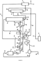
- Ammonia 10, optionally pre-heated in a pre-heater unit 1 is mixed with compressed air 13 in a mixing apparatus 3, pressured to a low pressure using an air compressor 2 operable at a low gas pressure, and the resulting ammonia/air mixture 14 is fed to an ammonia convertor 4, operating at a low pressure, where ammonia is oxidized over a suitable catalyst, thus obtaining a LP gaseous NO x gas/steam mixture 15, comprising water and NO.
- the heat of the mixture coming out of the ammonia convertor is recovered, after which the NO x gas/stream mixture is subsequently cooled down in a water cooler/condenser 9a to temperature where the water condenses, and an aqueous diluted nitric acid mixture 17 is separated from a gaseous NO x stream 18 .
- the LP gaseous NO x stream is further oxidized to further convert the NO to NO 2 and N 2 O 4 , and cooled down again in a cooler/separator 9b to separate out a aqueous diluted nitric acid mixture 21 which is directed to an absorber unit 6, commonly called absorption tower.
- the gaseous NO x stream 22 is send to a NO x gas compressor 5 wherein its pressure is elevated from a low pressure to a high pressure, being about equal to the absorber unit operating pressure, and the pressurized gaseous NO x stream 24 is sent to the absorber unit 6 too.
- the HP NO x gas reacts with water to produce a stream of raw nitric acid also containing residual NO x gas 27 , which is fed to a bleacher 7 over a valve 31.
- the residual NO x gas is then stripped out with a gaseous medium 16 such as an oxygen-containing gas or air, inside a bleacher unit 7, operating at low pressure; the bleacher unit is generally operated at about the same pressure as the ammonia convertor.
- the NO x -loaded stripping gas 19 is directed to the oxidation section, upstream of the NO x gas compressor 5 .
- the stripped nitric acid stream 29 from the bleacher unit 7 is then sent to storage for further processing.
- the drive power for both air compressor 2 and NO x gas compressor 5 originates from a tail-gas turbine 8 and a steam turbine or electric motor (not shown).
- the air used for the oxidation of ammonia is commonly denoted as primary air; the air used as stripping medium in the bleacher unit is commonly denoted as secondary air.
- the revamping of the nitric acid production plants to increase its capacity is commonly based on increasing the amount of primary air to the reactor, which leads to a proportional increase of the amount of nitric acid produced.
- the increase of the amount of primary air in the reactor entails the installation of a new air compressor or the revamping of the existing one.
- the increase of the primary air also causes a higher amount of gas to be processed into the subsequent NO x gas compressor, thus entailing the further revamping of the NO x gas compressor or the installation of a new one, and the modification or replacement of the tail-gas and/or the steam-turbines and/or the electrical motor. Otherwise, the NO x gas compressor would easily achieve its process limit, thus becoming the bottleneck of the plant.
- the revamping has significant drawbacks. First of all, it entails elevated costs for the modification or replacement of the existing equipment, i.e. the air compressor, the NO x gas compressor and the corresponding turbines and electrical motor. In addition, the revamping of the equipment is also technically demanding leading to long plant downtime.
- Another problem related to nitric acid production plants is the high amount of energy required in order to operate the NO x gas compressor. Consequently, a high amount of energy is required to achieve the targeted nitric acid production throughput.
- WO2018162150A1 discloses a dual pressure plant for the production of nitric acid comprising a reactor providing a gaseous effluent containing nitrogen oxides, an absorber unit in which nitrogen oxides react with water providing raw nitric acid and, the absorber unit operating at a pressure greater than the pressure of the reactor, a compressor elevating the pressure of the reactor effluent to the absorber unit pressure, the plant also comprising a first HP bleacher unit and a second LP bleacher unit, the first HP bleacher unit stripping with air the NO x gas from the output stream of the absorber unit, thus providing a partially stripped nitric acid stream and a nitrogen oxides-loaded air stream, the former being fed to the second LP-bleacher unit and the latter being recycled to the oxidation section, upstream of the NO x gas compressor.
- a further air compressor is also provided, which supplies the first HP bleacher unit with air. Hence, energy is required in order to operate a first HP bleacher unit at a high pressure and then recycle NO x gases to the delivery side of the NO x gas compressor.
- the goal of the disclosure is further achieved by operating a high-pressure bleacher unit in a dual pressure nitric acid production plant, according to claim 6 and dependent claims 7 to 10.
- the main embodiment of the disclosure has several advantages.
- a first advantage is that, according to the disclosure, the NO x gas compressor is not loaded anymore by the NO x -loaded stripping gas from the bleacher unit, as the NO x loaded stripping gas is directed to the downstream side of the NOx gas compressor, and combined with the HP gaseous NOx stream, thus requiring the NO x gas compressor to produce less work (for the same convertor throughput) or - put it differently - wherein the NO x gas compressor is able to handle an increased throughput of NO x -loaded gas from the oxidation section (at an increased convertor throughput).
- a second advantage is that the air compressor is now only pressurizing primary air for the convertor since the secondary air supply for the bleacher unit has now been replaced by a stream of an oxygen-rich gas provided at least partly by a high-pressure (HP) water electrolyser unit which is operated at a gas pressure of 9 to 30 bar, preferably 15 to 30 bar.
- HP high-pressure
- the air compressor is less loaded as it is only compressing primary air, thus requiring the air compressor to produce less work (for the same convertor throughput) or - put it differently - wherein the air compressor is able to handle an increased throughput of primary air (at an increased convertor throughput).
- a third advantage is that the air compressor or the NO x gas compressor does not need to be replaced by one with a higher throughput, and a higher nitric acid production can be achieved by only rerouting some of the gas streams.
- nitrogen oxides gases or NO x gases are assumed to comprise, as major NO x gas components, nitric oxide (NO), nitrogen dioxide (NO 2 ) and dinitrogen tetroxide gases (N 2 O 4 ).
- a low pressure is defined as a pressure ranging from 2 to 6 bar
- a high pressure is defined as a pressure ranging from 9 to 16 bar.
- a low pressure is always lower than a high pressure.
- means for directing are defined as means selected from the group of tubes, pipes, channels, conduits, ducts, and the like, capable of directing a fluid from a point A to a point B, which points A and B may be defined explicitly or implicitly, depending on the specific case.
- a dual pressure plant for the production of nitric acid comprises at least:
- an oxygen-rich gas is a gas comprising more oxygen than is on the average present in air.
- an oxygen-rich gas comprises more than 21 vol% of oxygen, more in particular more than 30 vol%, more than 40 vol%, more than 50 vol%, more than 60 vol%, more than 70 vol%, more than 80 vol%, more than 90 vol%, more than 95 vol%, and more than 99 vol%, more in particular comprises about 100 vol% of oxygen.
- the oxygen-rich gas differs from the gas used in the prior art in that it contains more oxygen, in particular more than 21 vol% of oxygen.
- the oxygen-rich gas may be obtained from mixing oxygen with air or any other gas., suitable for its primary purpose, i.e. as a stripping medium in a bleacher unit.
- the bleacher unit 7 can be any bleacher unit known in the prior art, such as, but not restricted to, a sieve tray bleacher unit, a random packing bleacher unit, or a structured packing bleacher unit.
- the compressor By directing the NO x -loaded stripping gas 19 to the downstream side of the NO x gas compressor 5, the compressor is not loaded anymore by the NO x -loaded stripping gas, thus requiring the NO x gas compressor to produce less work (for the same convertor throughput). Hence, the NO x gas compressor is able to handle an increased throughput of NO x -loaded gas from the oxidation section (at an increased convertor throughput).
- the air compressor 2 is now only pressurizing primary air for the convertor since the secondary air supply for the bleacher unit has now been replaced by a stream of an oxygen-rich gas from an HP oxygen-rich gas source provided at least partly by an HP water electrolyser unit, particularly a water electrolyser unit which is operated at a gas pressure of 30 bar.
- an HP water electrolyser unit particularly a water electrolyser unit which is operated at a gas pressure of 30 bar.
- the air compressor is less loaded as it is only compressing primary air, thus requiring the air compressor to produce less work (for the same convertor throughput).
- the air compressor is able to handle an increased throughput of primary air (at an increased convertor throughput).
- a water electrolyser is a device for the electrolysis of water, being the decomposition of water into oxygen and hydrogen gas, due to the passage of an electric current there through. This technique can be used to make hydrogen gas, a main component of hydrogen fuel, and breathable oxygen gas.
- a suitable high pressure water electrolyser may be comprised of:
- the anode and cathode can be made of nickel or steel, or mixtures thereof. Alternatively, for the purpose of enhancing the electrode reactions, the anode and cathode may contain catalysts that can be made of Iridium and Platinum, respectively.
- the diaphragm of an electrically insulating material is based on, for example, zirconia. The diaphragm has a porosity such that it forms a barrier against transport of hydrogen and oxygen gas bubbles, while containing a continuum of penetrated liquid electrolyte.
- Electrolysis cells are piled in series in stacks that compose the core of an electrolyser.
- the hydrogen and oxygen production for a given stack volume is proportional to the current density and inversely proportional to the stacking distance. Regardless of stack volume, the hydrogen and oxygen production is proportional to the total current.
- the electrolyser comprises auxiliaries such as a current rectifier, a water demineralization unit, a water pump and a cooling system, a hydrogen purification unit, and instrumentation.
- auxiliaries such as a current rectifier, a water demineralization unit, a water pump and a cooling system, a hydrogen purification unit, and instrumentation.
- the electrolyser is operated by applying a voltage corresponding to the standard potential plus the overpotential over each cell.
- the total voltage depends on the total number of cells of which the electrolyser is comprised.
- OH- ions generated at the cathode migrate through the electrolyte in the diaphragm to the anode, where they are consumed by the anode reaction. Electrons travel the opposite direction in an external circuit.
- the electrolyser may be operated at a temperature of 50 to 80 °C, or 60 to 80 °C, and a gas pressure of 9 to 30 bar, preferably 15 to 30 bar.
- the stripping medium 38 may be conditioned to a temperature ranging from ambient temperature to 120 °C, or from 50 °C to 120 °C, or from 80 °C to 120 °C, or from 90 to 120 °C, before it is directed into the bleacher unit 7.
- Bleaching of nitric acid in a bleacher unit in a nitric acid plant generally may be conditioned such that the temperature of the nitric acid is in the range of 30 to 60 °C (as measured inside the bleacher). By pre-conditioning the oxygen gas, the bleaching efficiency achieved in the bleacher 7 will be increased. Therefore, according to a specific embodiment, the plant according to the disclosure further comprises means (not shown) for heating the stripping medium 38, such as, but not limited to, a pre-heater or a heat exchange system.
- the bleacher unit 7 is a vertical bleaching tower, comprising:
- the above design of the bleacher unit has distinct advantages.
- the bleaching tower is a known restriction unit (bottle neck) in the nitric acid production.
- the problem is to meet the specifications of the product acid at high load.
- the design of the column should ensure uniform distribution and contact between the upward flowing gas (stripping medium) and the downward liquid stream (aqueous nitric acid solution) through the entire column.
- the advantage of the specific design is that an increased nitric acid production capacity and a reduction of the amount of stripping gas used, can be obtained, while at least maintaining the quality of the aqueous nitric acid solution, i.e. the low level of dissolved nitrogen oxide gases.
- the structured packing has a surface area of at least 250 m 2 /m 3 , preferably 450-750 m 2 /m 3 .
- the liquid distributor has a drip-point density of at least 30 dripping points per m 2 , preferably from 60 to -200 dripping points per m 2 .
- the ratio between the height of the structured packing and the vertical bleaching tower diameter is at least 1, preferably at least 1.5, more preferably at least 2.
- the stripping gas is an oxygen-rich gas, moving in a counter-current direction to the acid solution, i.e. the output product stream 27 and is in an air/acid solution ratio of lower than 75 m 3 air/m 3 acid solution, preferably lower than 45 m 3 air/m 3 acid solution, more preferably lower than 30 m 3 air/m 3 acid solution, even more preferably lower than 20 m 3 air/m 3 acid solution.
- the pressure drop over the vertical bleaching tower is between 25 mbar and 65 mbar.
- the plant according to the main embodiment further comprises a flash vessel 32 in fluid communication with the bleacher unit 7, wherein the flash vessel 32 comprises:
- the pressure of the stripped nitric acid stream 29 is rapidly reduced, and the dissolved gases, containing in particular NO x and oxygen gases, are evacuated from the stripped nitric acid stream 29.
- a first advantage is that the quality of the stripped nitric acid stream 29 can be improved, in the sense that it contains less dissolved gases, in particular NO x and oxygen gases.
- the amount of oxygen gases that will be released when the stripped nitric acid stream 29 is flashed down to atmospheric pressure in the storage tank may be reduced.
- a high concentration of oxygen forces the equilibrium for nitric oxide ⁇ -> nitrogen dioxide towards nitrogen dioxide, which results in brown gas emissions from the ventilation system of the storage tank.
- flashing of the stripped nitric acid stream 29 downstream the bleaching tower 7 and prior to storing the nitric acid product can result in less brown gas emissions coming out of the ventilation system of the product storage tank.
- a second advantage is that the gases 33b can be used to further improve the oxidation process in the oxidation stage 20, which is part of the upstream section of the NO x gas compressor 5, when they are (partly) directed to a point upstream of the water cooler/condenser 9a.
- the gases 33a may also be (partly) directed to a point directly upstream of the NO x gas compressor 5, where they do not contribute to the oxidation in the oxidation stage 20, but are compressed again to a high pressure (HP) to be fed to the absorber 6.
- HP high pressure
- a third advantage is that, by using an oxygen-rich gas as stripping medium 38 , the NO x -loaded stripping gas 33 has a much higher oxygen content than the NO x -loaded stripping gas according to the prior art. This will benefit the oxidation in the oxidation stage 20, providing a more effective oxidation of the gaseous NO x stream 18 . As a result, the tail gas 30 from the absorber 6 will be cleaner and less work will be required from a DeNOx unit (not shown) for treating the tail gas 30.
- the plant according to the main embodiment further comprises a second bleacher unit 34, in addition to the first bleacher unit 7, said second bleacher unit 34 comprising:
- the second bleacher unit 34 can be any bleacher unit known in the prior art, such as, but not restricted to, a sieve tray bleacher unit, a random packing bleacher unit or a structured packing bleacher unit.
- a first advantage is that, according to the findings of the inventors, the total amount of air consumed by the combination of the bleachers 7 and 34 is reduced with respect to the air consumption by the nitric acid plant according to the first embodiment of the disclosure, in which only bleacher 7 is used.
- a second advantage is that the quality of the stripped nitric acid stream 37 is improved, in the sense that it contains less dissolved gases, in particular NO x and oxygen gases.
- a third advantage is that the gases 36b can be used to further improve the oxidation process in the oxidation stage 20, which is part of the upstream section of the NO x gas compressor 5, when they are (partly) directed to a point upstream of the water cooler/condenser 9a.
- the gases 36a may also be (partly) directed to a point directly upstream of the NO x gas compressor 5 , where they do not contribute to the oxidation in the oxidation stage 20, but are compressed again to a high pressure (HP) to be fed to the absorber 6.
- HP high pressure
- a fourth advantage is that, by using an oxygen-rich gas 38a, 19a as stripping medium, the NO x -loaded stripping gas 36 has a much higher oxygen content than the NO x -loaded stripping gas according to the prior art. This will benefit the oxidation in the oxidation stage 20, providing a more effective oxidation of the gaseous NO x stream 18 . As a result, the tail gas 30 from the absorber 6 will be cleaner and less work will be required from a DeNOx unit (not shown) for treating the tail gas 30.
- the second bleacher unit 34 is a vertical bleaching tower, comprising:
- a method for operating a high-pressure bleacher unit in a plant according to the disclosure comprising the steps of:
- the bleacher unit 7 can be any bleacher unit known in the prior art, such as, but not restricted to, a sieve tray bleacher unit, a random packing bleacher unit or a structured packing bleacher unit.
- the inventors have now found that it is possible to reduce the work of a gas compressor, such as an air compressor or a NO x gas compressor, in a dual pressure nitric acid production plant, by utilizing the energy available from pressurized gas, more specifically NO x -loaded stripping gas from the bleacher unit. Indeed, by redirecting the pressurized gas downstream a NO x gas compressor, less work is required from the NO x gas compressor.
- the concept increases the convertor throughput and the nitric acid production rate in plants where the air compressor or the NO x gas compressor is a bottleneck.
- the HP oxygen-rich gas comprises more than 21 vol% of oxygen, in particular more than 95 vol% of oxygen.
- the HP oxygen-rich gas is provided by a high-pressure water electrolyser. It has been found that an improvement can be achieved by utilizing oxygen that already is pressurized. Indeed, the oxygen produced by a water electrolyser operating at higher pressure will be pressurized. Operating the water electrolyser at high pressure requires to pump water to the water electrolyser at a high pressure. However, pumping a liquid, in particular water, to a water electrolyser requires significantly less power than the compression of an oxygen-containing gas, in particular air, for use in a dual pressure nitric acid production plant.
- the integration of a high pressure water electrolyser with a dual pressure nitric acid production plant in which pressurized oxygen is supplied to the dual pressure nitric acid production plant, provides a large benefit in the form of energy saving associated with the compression of the oxygen-rich gas before its introduction in the dual pressure nitric acid production plant.
- the oxygen-containing gas is the oxygen-rich gas provided by the water electrolyser unit or a mixture of the oxygen-rich gas provided by the water electrolyser unit and air compressed by the air compressor.
- the method further comprises the step of: d) pre-heating the HP oxygen-rich gas as a stripping medium 38 to a temperature ranging from ambient temperature to 120 °C, or from 50 °C to 120 °C, or from 80 °C to 120 °C, or from 90 to 120 °C.
- Bleaching of nitric acid in a bleacher unit in a nitric acid plant generally may be performed such that the temperature of the nitric acid is in the range of 30 to 60 °C (as measured inside the bleacher). By pre-conditioning the oxygen gas, the bleaching efficiency achieved in the bleacher 7 will be increased.
- the method further comprises, in a plant according to the second embodiment, the steps of:
- Flashing of the stripped nitric acid stream 29 improves the bleaching of this nitric acid stream by removing additional dissolved nitrogen oxides gases and allows for the recovery and reuse of oxygen gas, originally provided to the bleacher unit 7.
- the recovered oxygen can be recycled to either the ammonia burner 4, the oxidation stage 20, or the absorber unit 6.
- oxygen is recycled to the ammonia burner 4 or the oxidation stage 20, the oxidation of ammonia to nitric oxide and the oxidation of nitric oxide to nitrogen dioxide and dinitrogen tetroxide will be respectively increased.
- the efficiency of the absorption in the absorber unit 6 will be increased through increased conversion of nitric oxide to nitrogen dioxide and dinitrogen tetroxide.
- the tail gas 30 from the absorber 6 will be cleaner and less work will be required from a DeNOx unit (not shown) for treating the tail gas 30.
- the amount of oxygen that will be released when the stripped nitric acid stream 29 is flashed down to atmospheric pressure in the storage tank is reduced.
- flashing of the stripped nitric acid stream 29 downstream the bleaching tower 7 and prior to storing the nitric acid product results in less brown gas emissions coming out of the ventilation system of the product storage tank.
- the method further comprises, in a plant according to the third embodiment, the steps of:
- Stripping of the stripped nitric acid stream 29 improves the bleaching of this nitric acid stream by removing additional dissolved nitrogen oxides gases and allows for the recovery and reuse of oxygen gas, originally provided to the bleacher unit 7.
- the recovered oxygen can be recycled to either the ammonia burner 4, the oxidation stage 20, or the absorber unit 6.
- oxygen is recycled to the ammonia burner 4 or the oxidation stage 20, the oxidation of ammonia to nitric oxide and the oxidation of nitric oxide to nitrogen dioxide and dinitrogen tetroxide will be respectively increased.
- the efficiency of the absorption in the absorber unit 6 will be increased through increased conversion of nitric oxide to nitrogen dioxide and dinitrogen tetroxide.
- the tail gas 30 from the absorber 6 will be cleaner and less work will be required from a DeNO x unit (not shown) for treating the tail gas 30.
- the amount of oxygen that will be released when the stripped nitric acid stream 29 is flashed down to atmospheric pressure in the storage tank, is reduced.
- flashing of the stripped nitric acid stream 29 downstream the bleaching tower 7 and prior to storing the nitric acid product results in less brown gas emissions coming out of the ventilation system of the product storage tank.
- any embodiment of a dual pressure nitric acid production plant according to the disclosure for recovery of energy from a high-pressure bleacher unit operating in the dual pressure nitric acid production plant, is disclosed.
- any embodiment of a dual pressure nitric acid production plant according to the disclosure for providing energy savings in the dual pressure nitric acid production plant, specifically by supplying pressurized oxygen from a high pressure water electrolyser to a high-pressure bleacher unit operating in said dual pressure nitric acid production plant, is disclosed.
- the absorber unit was operated at a pressure ranging from 11.9 bar to 12.0 bar.
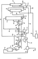
- Pressurized oxygen gas 38 from an external, pressurized HP water electrolyser system 60 was fed into the nitric acid bleacher unit 7 as the stripping medium.
- the NO x -loaded stripping gas 19 was redirected downstream to the NO x gas compressor 5. Since the bleacher unit 7 operated at a pressure level of NO x gas compressor outlet, the gases from the bleacher unit 7, containing nitrogen oxides gases, could be injected downstream the NO x gas compressor 5. Compression work in the air compressor was reduced by 31.8 kWh/t 100% nitric acid. Compression work in the NO x gas compressor was reduced by 6 kWh/t 100% nitric acid without any impact on the emissions from the nitric acid storage tank.
- the absorber unit was operated at a pressure ranging from 11.9 bar to 12.0 bar.
- the nitric acid produced from the high-pressure bleacher unit 7 was flashed down into a flash-vessel 32.
- the flash-vessel contained a separation device to ensure that the gas and liquid phase were well separated.
- the pressure was reduced to a pressure substantially equal to the pressure upstream the low-pressure cooler condenser 9b or upstream the nitrogen oxides gas compressor 5.
- the gases 33 from the flash vessel 32 were then directed to either upstream the low-pressure cooler condenser 9b or upstream the nitrogen gas compressor 5. Compression work in the air compressor was reduced by 31.8 kWh/t 100% nitric acid.
- the absorber unit was operated at a pressure ranging from 11.9 bar to 12.0 bar.
- the stripped nitric acid stream 29 from the high-pressure bleacher unit 7 was flashed down through a valve (not shown) into a low-pressure bleacher unit 34.
- the low-pressure bleacher unit 34 operated at a pressure of 5 bar that the gas 36 from the low-pressure bleacher unit 34 could be returned to the oxidation stage 20 upstream the low-pressure cooler condenser 9b or upstream the NO x gas compressor 5.
- the low-pressure bleacher unit 34 was operated partly by oxygen produced from a high-pressure water electrolyser 60 and provided as stream 38a, and partly by the NO x -loaded stripping gas from the bleaching tower 7, provided as stream 19a. Compression work in the air compressor was reduced by 31.9 kWh/t 100% nitric acid. Compression work in the NO x gas compressor was reduced by 6 kWh/t 100% nitric acid without any impact on the emissions from the nitric acid storage tank.
- the absorber unit was operated at a pressure ranging from 11.9 bar to 12.0 bar.
- the stripped nitric acid stream 29 from the high-pressure bleacher unit 7 was flashed down through a valve (not shown) into a low-pressure bleacher unit 34.
- the low-pressure bleacher unit 34 operated at such a pressure that the gas 36 from the low-pressure bleacher unit 34 could be returned to the oxidation stage 20 upstream the low-pressure cooler condenser 9b or upstream the NO x gas compressor 5.
- the low-pressure bleacher unit 34 was operated by oxygen produced from a high-pressure water electrolyser 60 and provided as stream 38a.
- Compression work in the air compressor was reduced by 31.9 kWh/t 100% nitric acid.
- Compression work in the NO x gas compressor was reduced by 16.2 kWh/t 100% nitric acid without any impact on the emissions from the nitric acid storage tank.
- a reduction of 6.8 % in the amount of bleaching air required in Example 1 was observed.
Landscapes
- Chemical & Material Sciences (AREA)
- Organic Chemistry (AREA)
- Chemical Kinetics & Catalysis (AREA)
- Inorganic Chemistry (AREA)
- Engineering & Computer Science (AREA)
- Materials Engineering (AREA)
- Electrochemistry (AREA)
- Metallurgy (AREA)
- General Chemical & Material Sciences (AREA)
- Biomedical Technology (AREA)
- Oil, Petroleum & Natural Gas (AREA)
- Analytical Chemistry (AREA)
- Health & Medical Sciences (AREA)
- Environmental & Geological Engineering (AREA)
- Organic Low-Molecular-Weight Compounds And Preparation Thereof (AREA)
- Treating Waste Gases (AREA)
- Separation By Low-Temperature Treatments (AREA)
- Gas Separation By Absorption (AREA)
- Physical Water Treatments (AREA)
Claims (10)
- Doppeldruckanlage zur Herstellung von Salpetersäure, Folgendes umfassend:- einen Luftkompressor (2), der betriebsfähig ist, um Luft (12) auf einen Druck im Bereich von 2 bar bis 6 bar (Niederdruck, ND) zu bringen;- einen Konverter (4), der bei einem Niederdruck (ND) betrieben wird, der betriebsfähig ist, mit einem Strom einer Ammoniak-/Druckluftmischung (14) bei Niederdruck (ND) beschickt zu werden, um das Ammoniak zu oxidieren und eine gasförmige NOx-ND-Gas-/Dampfmischung (15) zu erzeugen, die Wasser und NO umfasst;- einen NOx-Gaskompressor (5), der betriebsfähig ist, um den Druck eines gasförmigen NOx-Stroms (22) von einem Niederdruck (ND) auf einem Druck im Bereich von 9 bar bis 16 bar (Hochdruck, HD) zu erhöhen, der auf seiner stromabwärtigen Seite einem gasförmigen NOx-HD-Strom (24) entsteht;- eine Absorbereinheit (6), die bei einem hohen Druck (HD) betrieben wird, die betriebsfähig ist, um die Stickstoffoxide, die in dem gasförmigen NOx-HD-Strom (24) enthalten sind, mit Wasser umzusetzen, wobei die Absorbereinheit (6) einen Ausgangsproduktstrom (27), der Salpetersäure und gelöste Stickstoffoxide enthält, und ein Restgas (30) bereitstellt; und- eine Bleicheinheit (7), die betriebsfähig ist, um gelöste Stickstoffoxide aus dem Ausgangsproduktstrom (27) mit einem Strippmedium (38) zu strippen, wobei ein gestrippter Salpetersäure-Strom (29) und ein mit NOx beladenes Strippgas (19) bereitgestellt werden;wobei:- die Bleicheinheit (7) bei einem hohen Druck (HD) betreibt, der ungefähr gleich dem Druck ist, bei dem die Absorbereinheit (6) betrieben wird;- die Bleicheinheit (7) in Fluidverbindung mit einer Quelle von sauerstoffreichem HD-Gas (60) steht, um die Bleicheinheit (7) mit einem sauerstoffreichen HD-Gas als Strippmedium (38) zu bereitstellen;- die Anlage ein Mittel zum Leiten des mit NOx beladenen Strippgases (19) auf die stromabwärtige Seite des NOx-Gaskompressors (5) umfasst;wobei die Anlage dadurch gekennzeichnet ist, dass sie weiterhin Folgendes umfasst- einen Hochdruck-(HD)-Wasserelektrolyseur (60), der in Fluidverbindung mit der Bleicheinheit (7) steht, um das sauerstoffreiche Hochdruck-(HD)-Gas, das als Strippmedium (38) verwendet werden soll, allein oder mit Druckluft oder einem anderen geeigneten Gas gemischt bereitzustellen.
- Anlage nach Anspruch 1, wobei das sauerstoffreiche HD-Gas mehr als 21 Vol.-% Sauerstoff, insbesondere mehr als 95 Vol.-% Sauerstoff umfasst.
- Anlage nach einem der Ansprüche 1 bis 2, wobei die Bleicheinheit (7) ein vertikaler Bleichturm ist, Folgendes umfassend:- einen strukturierten Füllung; und- einen Flüssigkeitsverteiler, der einen Beschickungskasten mit einem gezahnten Wehr zur Verteilung des Ausgangsproduktstroms (27), der gelöste Stickstoffoxide umfasst, durch aufwärts gerichtete zähnen des gezahnten Wehrs in perforierte Schalen des Flüssigkeitsverteilers umfasst und über dem strukturierten Füllung angeordnet ist zum Verteilen der wässrigen Salpetersäure-Lösung, welche die gelösten Stickstoffoxide umfasst, auf den strukturierten Füllung.
- Anlage nach einem der Ansprüche 1 bis 3, weiterhin einen Entspannungsbehälter (32) in Fluidverbindung mit der Bleicheinheit (7) umfassend, der Folgendes umfasst:- einen Einlass für den gestrippten Salpetersäure-Strom (29) in Fluidverbindung mit der Bleicheinheit (7); wobei der gestrippte Salpetersäure-Strom (29) schnell von einem hohen Druck (HD) auf einen niedrigen Druck (ND) druckreduziert (entspannt) wird;- einen ersten Auslass für Gase (33), die in dem Entspannungsbehälter (32) erzeugt werden, in Fluidverbindung mit einem stromaufwärtigen Abschnitt des NOx-Gaskompressors (5); und- einen zweiten Auslass zum Aufnehmen des entspannten Salpetersäure-Stroms (35) aus dem Entspannungsbehälter (32) .
- Anlage nach einem der Ansprüche 1 bis 3, weiterhin eine zweite Bleicheinheit (34) umfassend, die Folgendes umfasst:- einen ersten Einlass für den gestrippten Salpetersäure-Strom (29) in Fluidverbindung mit der Bleicheinheit (7);- einen zweiten Einlass für einen Strippgasstrom (39);- einen ersten Auslass für einen mit NOx beladenen Strippgasstrom (36) in Fluidverbindung mit einem stromaufwärtigen Abschnitt des NOx-Gaskompressors (5); und- einen zweiten Auslass zum Aufnehmen des gebleichten Salpetersäure-Stroms (37) aus der zweiten Bleicheinheit (34) ;wobei:- die zweite Bleicheinheit (34) bei einem niedrigen Druck (ND) betreibt, der niedriger ist als der Druck, bei dem die Bleicheinheit (7) betrieben wird;- die zweite Bleicheinheit (34) in Fluidverbindung mit einer Quelle von sauerstoffreichem HD-Gas (38a) steht, um die zweite Bleicheinheit (34) mit einem sauerstoffreichen HD-Gas als Strippmedium (38a) zu bereitstellen; und- die Anlage ein Mittel zum Leiten des mit NOx beladenen Strippgases (36) auf die stromaufwärtige Seite des NOx-Gaskompressors (5) umfasst.
- Verfahren zum Betreiben einer Hochdruckbleicheinheit in einer Anlage nach einem der Ansprüche 1 bis 5, die folgenden Schritte umfassend:a) Betreiben der Bleicheinheit (7) bei einem hohen Druck (HD), der ungefähr gleich dem Druck ist, bei dem die Absorbereinheit (6) betrieben wird;b) Bereitstellen der Bleicheinheit (7) mit einem sauerstoffreichen HD-Gas als ein Strippmedium (38); undc) Leiten des mit NOx beladenen Strippgases (19) auf die stromabwärtige Seite des NOx-Gaskompressors (5);wobei das sauerstoffreiche HD-Gas durch einen Hochdruckwasserelektrolyseur bereitgestellt wird.
- Verfahren nach Anspruch 6, wobei das sauerstoffreiche HD-Gas mehr als 21 Vol.-% Sauerstoff, insbesondere mehr als 95 Vol.-% Sauerstoff umfasst.
- Verfahren nach Anspruch 6 oder 7, wobei das Verfahren weiterhin in einer Anlage nach einem der Ansprüche 1 bis 6 vor Schritt b) den folgenden Schritt umfasst:
d) Vorwärmen des sauerstoffreichen HD-Gases als ein Strippmedium (38) auf eine Temperatur im Bereich von Umgebungstemperatur bis 120 °C, oder von 50 °C bis 120 °C, oder von 80 °C bis 120 °C, oder von 90 bis 120 °C. - Verfahren nach einem der Ansprüche 6 bis 8, wobei das Verfahren in einer Anlage nach Anspruch 4 weiterhin die folgenden Schritte umfasst:e) Entspannen des gestrippten Salpetersäure-Stroms (29) von einem hohen Druck (HD) auf einen niedrigen Druck (ND) undf) Leiten von Gasen (33), die in dem Entspannungsbehälter (32) erzeugt werden, zu einem stromaufwärtigen Abschnitt des NOx-Gaskompressors (5).
- Verfahren nach einem der Ansprüche 6 bis 9, wobei das Verfahren in einer Anlage nach Anspruch 6 weiterhin die folgenden Schritte umfasst:g) Betreiben der zweiten Bleicheinheit (34) bei einem niedrigen Druck (ND), der niedriger ist als der Druck, bei dem die Bleicheinheit (7) betrieben wird;h) Bereitstellen der zweiten Bleicheinheit (34) mit einem sauerstoffreichen HD-Gas als ein Strippmedium (38); undi) Leiten des mit NOx beladenen Strippgases (36) auf die stromaufwärtige Seite des NOx-Gaskompressors (5).
Applications Claiming Priority (2)
| Application Number | Priority Date | Filing Date | Title |
|---|---|---|---|
| EP20195977.2A EP3967657A1 (de) | 2020-09-14 | 2020-09-14 | Doppeldruckanlage zur herstellung von salpetersäure und verfahren zum betrieb davon |
| PCT/EP2021/075157 WO2022053698A1 (en) | 2020-09-14 | 2021-09-14 | Dual pressure plant for the production of nitric acid and method for operating same |
Publications (3)
| Publication Number | Publication Date |
|---|---|
| EP4211076A1 EP4211076A1 (de) | 2023-07-19 |
| EP4211076C0 EP4211076C0 (de) | 2024-10-09 |
| EP4211076B1 true EP4211076B1 (de) | 2024-10-09 |
Family
ID=72474248
Family Applications (2)
| Application Number | Title | Priority Date | Filing Date |
|---|---|---|---|
| EP20195977.2A Withdrawn EP3967657A1 (de) | 2020-09-14 | 2020-09-14 | Doppeldruckanlage zur herstellung von salpetersäure und verfahren zum betrieb davon |
| EP21765811.1A Active EP4211076B1 (de) | 2020-09-14 | 2021-09-14 | Doppeldruckanlage zur herstellung von salpetersäure und verfahren zum betrieb davon |
Family Applications Before (1)
| Application Number | Title | Priority Date | Filing Date |
|---|---|---|---|
| EP20195977.2A Withdrawn EP3967657A1 (de) | 2020-09-14 | 2020-09-14 | Doppeldruckanlage zur herstellung von salpetersäure und verfahren zum betrieb davon |
Country Status (11)
| Country | Link |
|---|---|
| US (1) | US20230264957A1 (de) |
| EP (2) | EP3967657A1 (de) |
| CN (1) | CN115996889B (de) |
| AU (1) | AU2021341519A1 (de) |
| CA (1) | CA3190537A1 (de) |
| CL (1) | CL2023000710A1 (de) |
| CO (1) | CO2023004462A2 (de) |
| ES (1) | ES2993712T3 (de) |
| PL (1) | PL4211076T3 (de) |
| WO (1) | WO2022053698A1 (de) |
| ZA (1) | ZA202304297B (de) |
Family Cites Families (9)
| Publication number | Priority date | Publication date | Assignee | Title |
|---|---|---|---|---|
| US3881004A (en) * | 1972-12-29 | 1975-04-29 | Masar Inc | Ammonium nitrate plant |
| AT368749B (de) * | 1981-02-25 | 1982-11-10 | Bbc Brown Boveri & Cie | Verfahren zur kontinuierlichen herstellung von stickoxyd (no) und vorrichtung zur durchfuehrung des verfahrens |
| US9772129B2 (en) * | 2012-08-17 | 2017-09-26 | Vinod Kumar Arora | Ammonia plant upgrading-multistage integrated chilling of process air compressor with ammonia compressor followed by air flow split and multistage air preheating to secondary ammonia reformer |
| JP6081431B2 (ja) * | 2014-11-05 | 2017-02-15 | 本田技研工業株式会社 | 差圧式高圧水電解装置 |
| PL3515861T3 (pl) * | 2016-09-19 | 2021-08-16 | Stamicarbon B.V. | Instalacja i sposób wytwarzania kwasu azotowego |
| EP3372556A1 (de) | 2017-03-07 | 2018-09-12 | Casale Sa | Anlage zur herstellung von salpetersäure, zugehöriges verfahren und verfahren zur umarbeitung |
| WO2020035521A1 (en) * | 2018-08-17 | 2020-02-20 | Yara International Asa | High energy recovery nitric acid process using liquid oxygen containing fluid |
| CN208776318U (zh) * | 2018-09-28 | 2019-04-23 | 天津华景化工新技术开发有限公司 | 一种稀硝酸的生产系统 |
| CN109516445B (zh) * | 2018-12-05 | 2021-07-23 | 四川大学 | 电解水与空气分离联用制硝酸的封闭循环工艺 |
-
2020
- 2020-09-14 EP EP20195977.2A patent/EP3967657A1/de not_active Withdrawn
-
2021
- 2021-09-14 EP EP21765811.1A patent/EP4211076B1/de active Active
- 2021-09-14 WO PCT/EP2021/075157 patent/WO2022053698A1/en not_active Ceased
- 2021-09-14 ES ES21765811T patent/ES2993712T3/es active Active
- 2021-09-14 AU AU2021341519A patent/AU2021341519A1/en active Pending
- 2021-09-14 CN CN202180053142.2A patent/CN115996889B/zh active Active
- 2021-09-14 PL PL21765811.1T patent/PL4211076T3/pl unknown
- 2021-09-14 CA CA3190537A patent/CA3190537A1/en active Pending
- 2021-09-14 US US18/024,170 patent/US20230264957A1/en active Pending
-
2023
- 2023-03-13 CL CL2023000710A patent/CL2023000710A1/es unknown
- 2023-04-11 CO CONC2023/0004462A patent/CO2023004462A2/es unknown
- 2023-04-11 ZA ZA2023/04297A patent/ZA202304297B/en unknown
Also Published As
| Publication number | Publication date |
|---|---|
| EP4211076A1 (de) | 2023-07-19 |
| US20230264957A1 (en) | 2023-08-24 |
| CN115996889A (zh) | 2023-04-21 |
| ZA202304297B (en) | 2025-01-29 |
| AU2021341519A1 (en) | 2023-04-13 |
| CL2023000710A1 (es) | 2023-10-20 |
| CN115996889B (zh) | 2024-10-22 |
| EP3967657A1 (de) | 2022-03-16 |
| CO2023004462A2 (es) | 2023-07-10 |
| EP4211076C0 (de) | 2024-10-09 |
| ES2993712T3 (en) | 2025-01-07 |
| PL4211076T3 (pl) | 2025-02-17 |
| WO2022053698A1 (en) | 2022-03-17 |
| CA3190537A1 (en) | 2022-03-17 |
Similar Documents
| Publication | Publication Date | Title |
|---|---|---|
| EP4392368B1 (de) | Doppeldrucksystem zur herstellung von salpetersäure und verfahren zum betrieb davon | |
| EP4238932A1 (de) | Doppeldrucksystem zur herstellung von salpetersäure und verfahren zum betrieb davon | |
| EP4209453A1 (de) | Doppeldrucksystem zur herstellung von salpetersäure und verfahren zum betrieb davon | |
| EP4204358B1 (de) | Einzeldruckanlage zur herstellung von salpetersäure und verfahren zum betrieb davon | |
| EP4392367B1 (de) | Doppeldrucksystem zur herstellung von salpetersäure und verfahren zum betrieb davon | |
| EP4392369B1 (de) | Doppeldrucksystem zur herstellung von salpetersäure und verfahren zum betrieb davon | |
| EP4211076B1 (de) | Doppeldruckanlage zur herstellung von salpetersäure und verfahren zum betrieb davon | |
| EP4392370B1 (de) | Mono-drucksystem zur herstellung von salpetersäure und verfahren zu dessen betrieb | |
| EP4392366B1 (de) | Mono-drucksystem zur herstellung von salpetersäure und verfahren zu dessen betrieb | |
| EP4392371B1 (de) | Monodrucksystem zur herstellung von salpetersäure und verfahren zum betrieb davon | |
| RU2836170C1 (ru) | Установка двойного давления для производства азотной кислоты и способ ее эксплуатации | |
| RU2846521C1 (ru) | Установка по производству азотной кислоты и способ ее эксплуатации | |
| EP4238933A1 (de) | Monodrucksystem zur herstellung von salpetersäure und verfahren zum betrieb davon | |
| EP4209454A1 (de) | Monodrucksystem zur herstellung von salpetersäure und verfahren zum betrieb davon |
Legal Events
| Date | Code | Title | Description |
|---|---|---|---|
| STAA | Information on the status of an ep patent application or granted ep patent |
Free format text: STATUS: UNKNOWN |
|
| STAA | Information on the status of an ep patent application or granted ep patent |
Free format text: STATUS: THE INTERNATIONAL PUBLICATION HAS BEEN MADE |
|
| PUAI | Public reference made under article 153(3) epc to a published international application that has entered the european phase |
Free format text: ORIGINAL CODE: 0009012 |
|
| STAA | Information on the status of an ep patent application or granted ep patent |
Free format text: STATUS: REQUEST FOR EXAMINATION WAS MADE |
|
| 17P | Request for examination filed |
Effective date: 20230330 |
|
| AK | Designated contracting states |
Kind code of ref document: A1 Designated state(s): AL AT BE BG CH CY CZ DE DK EE ES FI FR GB GR HR HU IE IS IT LI LT LU LV MC MK MT NL NO PL PT RO RS SE SI SK SM TR |
|
| DAV | Request for validation of the european patent (deleted) | ||
| DAX | Request for extension of the european patent (deleted) | ||
| GRAP | Despatch of communication of intention to grant a patent |
Free format text: ORIGINAL CODE: EPIDOSNIGR1 |
|
| STAA | Information on the status of an ep patent application or granted ep patent |
Free format text: STATUS: GRANT OF PATENT IS INTENDED |
|
| RIC1 | Information provided on ipc code assigned before grant |
Ipc: C25B 9/77 20210101ALI20240411BHEP Ipc: C25B 1/50 20210101ALI20240411BHEP Ipc: C25B 1/04 20210101ALI20240411BHEP Ipc: B01D 53/56 20060101ALI20240411BHEP Ipc: C01B 21/40 20060101ALI20240411BHEP Ipc: C01B 21/28 20060101ALI20240411BHEP Ipc: C01B 21/26 20060101AFI20240411BHEP |
|
| INTG | Intention to grant announced |
Effective date: 20240514 |
|
| GRAS | Grant fee paid |
Free format text: ORIGINAL CODE: EPIDOSNIGR3 |
|
| GRAA | (expected) grant |
Free format text: ORIGINAL CODE: 0009210 |
|
| STAA | Information on the status of an ep patent application or granted ep patent |
Free format text: STATUS: THE PATENT HAS BEEN GRANTED |
|
| AK | Designated contracting states |
Kind code of ref document: B1 Designated state(s): AL AT BE BG CH CY CZ DE DK EE ES FI FR GB GR HR HU IE IS IT LI LT LU LV MC MK MT NL NO PL PT RO RS SE SI SK SM TR |
|
| REG | Reference to a national code |
Ref country code: CH Ref legal event code: EP |
|
| REG | Reference to a national code |
Ref country code: DE Ref legal event code: R096 Ref document number: 602021020025 Country of ref document: DE |
|
| REG | Reference to a national code |
Ref country code: IE Ref legal event code: FG4D |
|
| U01 | Request for unitary effect filed |
Effective date: 20241014 |
|
| U07 | Unitary effect registered |
Designated state(s): AT BE BG DE DK EE FI FR IT LT LU LV MT NL PT RO SE SI Effective date: 20241030 |
|
| REG | Reference to a national code |
Ref country code: ES Ref legal event code: FG2A Ref document number: 2993712 Country of ref document: ES Kind code of ref document: T3 Effective date: 20250107 |
|
| PG25 | Lapsed in a contracting state [announced via postgrant information from national office to epo] |
Ref country code: IS Free format text: LAPSE BECAUSE OF FAILURE TO SUBMIT A TRANSLATION OF THE DESCRIPTION OR TO PAY THE FEE WITHIN THE PRESCRIBED TIME-LIMIT Effective date: 20250209 Ref country code: HR Free format text: LAPSE BECAUSE OF FAILURE TO SUBMIT A TRANSLATION OF THE DESCRIPTION OR TO PAY THE FEE WITHIN THE PRESCRIBED TIME-LIMIT Effective date: 20241009 |
|
| PG25 | Lapsed in a contracting state [announced via postgrant information from national office to epo] |
Ref country code: GR Free format text: LAPSE BECAUSE OF FAILURE TO SUBMIT A TRANSLATION OF THE DESCRIPTION OR TO PAY THE FEE WITHIN THE PRESCRIBED TIME-LIMIT Effective date: 20250110 |
|
| PG25 | Lapsed in a contracting state [announced via postgrant information from national office to epo] |
Ref country code: RS Free format text: LAPSE BECAUSE OF FAILURE TO SUBMIT A TRANSLATION OF THE DESCRIPTION OR TO PAY THE FEE WITHIN THE PRESCRIBED TIME-LIMIT Effective date: 20250109 |
|
| PG25 | Lapsed in a contracting state [announced via postgrant information from national office to epo] |
Ref country code: SM Free format text: LAPSE BECAUSE OF FAILURE TO SUBMIT A TRANSLATION OF THE DESCRIPTION OR TO PAY THE FEE WITHIN THE PRESCRIBED TIME-LIMIT Effective date: 20241009 |
|
| PG25 | Lapsed in a contracting state [announced via postgrant information from national office to epo] |
Ref country code: SK Free format text: LAPSE BECAUSE OF FAILURE TO SUBMIT A TRANSLATION OF THE DESCRIPTION OR TO PAY THE FEE WITHIN THE PRESCRIBED TIME-LIMIT Effective date: 20241009 |
|
| PG25 | Lapsed in a contracting state [announced via postgrant information from national office to epo] |
Ref country code: CZ Free format text: LAPSE BECAUSE OF FAILURE TO SUBMIT A TRANSLATION OF THE DESCRIPTION OR TO PAY THE FEE WITHIN THE PRESCRIBED TIME-LIMIT Effective date: 20241009 |
|
| PLBE | No opposition filed within time limit |
Free format text: ORIGINAL CODE: 0009261 |
|
| STAA | Information on the status of an ep patent application or granted ep patent |
Free format text: STATUS: NO OPPOSITION FILED WITHIN TIME LIMIT |
|
| 26N | No opposition filed |
Effective date: 20250710 |
|
| PGFP | Annual fee paid to national office [announced via postgrant information from national office to epo] |
Ref country code: NO Payment date: 20250919 Year of fee payment: 5 |
|
| PGFP | Annual fee paid to national office [announced via postgrant information from national office to epo] |
Ref country code: PL Payment date: 20250902 Year of fee payment: 5 |
|
| U20 | Renewal fee for the european patent with unitary effect paid |
Year of fee payment: 5 Effective date: 20250923 |