EP4210385A1 - Procédé et appareil de communication - Google Patents
Procédé et appareil de communication Download PDFInfo
- Publication number
- EP4210385A1 EP4210385A1 EP20954745.4A EP20954745A EP4210385A1 EP 4210385 A1 EP4210385 A1 EP 4210385A1 EP 20954745 A EP20954745 A EP 20954745A EP 4210385 A1 EP4210385 A1 EP 4210385A1
- Authority
- EP
- European Patent Office
- Prior art keywords
- information
- amf
- plmn
- cho
- execution condition
- Prior art date
- Legal status (The legal status is an assumption and is not a legal conclusion. Google has not performed a legal analysis and makes no representation as to the accuracy of the status listed.)
- Pending
Links
- 238000000034 method Methods 0.000 title claims abstract description 143
- 238000004891 communication Methods 0.000 title claims abstract description 122
- 230000015654 memory Effects 0.000 claims description 67
- 230000006870 function Effects 0.000 claims description 55
- 238000004590 computer program Methods 0.000 claims description 10
- 230000007246 mechanism Effects 0.000 abstract description 13
- 210000004027 cell Anatomy 0.000 description 435
- 238000013461 design Methods 0.000 description 52
- 238000012545 processing Methods 0.000 description 40
- 210000001057 smooth muscle myoblast Anatomy 0.000 description 29
- 238000010586 diagram Methods 0.000 description 20
- CIWBSHSKHKDKBQ-JLAZNSOCSA-N Ascorbic acid Chemical compound OC[C@H](O)[C@H]1OC(=O)C(O)=C1O CIWBSHSKHKDKBQ-JLAZNSOCSA-N 0.000 description 18
- 238000002360 preparation method Methods 0.000 description 16
- 230000008569 process Effects 0.000 description 15
- 230000004044 response Effects 0.000 description 12
- 238000001228 spectrum Methods 0.000 description 11
- 230000005540 biological transmission Effects 0.000 description 6
- 238000013507 mapping Methods 0.000 description 6
- 230000008878 coupling Effects 0.000 description 5
- 238000010168 coupling process Methods 0.000 description 5
- 238000005859 coupling reaction Methods 0.000 description 5
- 238000005259 measurement Methods 0.000 description 5
- 230000001172 regenerating effect Effects 0.000 description 5
- 230000001360 synchronised effect Effects 0.000 description 4
- 102100022734 Acyl carrier protein, mitochondrial Human genes 0.000 description 3
- 101000678845 Homo sapiens Acyl carrier protein, mitochondrial Proteins 0.000 description 3
- 230000008859 change Effects 0.000 description 3
- 238000005516 engineering process Methods 0.000 description 3
- 230000003068 static effect Effects 0.000 description 3
- 230000009471 action Effects 0.000 description 2
- 230000006978 adaptation Effects 0.000 description 2
- 230000003190 augmentative effect Effects 0.000 description 2
- 238000006243 chemical reaction Methods 0.000 description 2
- 101100055418 Saccharomyces cerevisiae (strain ATCC 204508 / S288c) AMF1 gene Proteins 0.000 description 1
- 230000008901 benefit Effects 0.000 description 1
- 230000006835 compression Effects 0.000 description 1
- 238000007906 compression Methods 0.000 description 1
- 239000013256 coordination polymer Substances 0.000 description 1
- 230000004069 differentiation Effects 0.000 description 1
- 239000011521 glass Substances 0.000 description 1
- 230000003993 interaction Effects 0.000 description 1
- 230000001788 irregular Effects 0.000 description 1
- 238000012423 maintenance Methods 0.000 description 1
- 238000012544 monitoring process Methods 0.000 description 1
- 230000003287 optical effect Effects 0.000 description 1
- 239000004984 smart glass Substances 0.000 description 1
- XLYOFNOQVPJJNP-UHFFFAOYSA-N water Substances O XLYOFNOQVPJJNP-UHFFFAOYSA-N 0.000 description 1
Images


Classifications
-
- H—ELECTRICITY
- H04—ELECTRIC COMMUNICATION TECHNIQUE
- H04W—WIRELESS COMMUNICATION NETWORKS
- H04W36/00—Hand-off or reselection arrangements
- H04W36/0005—Control or signalling for completing the hand-off
- H04W36/0083—Determination of parameters used for hand-off, e.g. generation or modification of neighbour cell lists
- H04W36/00835—Determination of neighbour cell lists
-
- H—ELECTRICITY
- H04—ELECTRIC COMMUNICATION TECHNIQUE
- H04W—WIRELESS COMMUNICATION NETWORKS
- H04W12/00—Security arrangements; Authentication; Protecting privacy or anonymity
- H04W12/04—Key management, e.g. using generic bootstrapping architecture [GBA]
-
- H—ELECTRICITY
- H04—ELECTRIC COMMUNICATION TECHNIQUE
- H04W—WIRELESS COMMUNICATION NETWORKS
- H04W36/00—Hand-off or reselection arrangements
- H04W36/34—Reselection control
- H04W36/36—Reselection control by user or terminal equipment
- H04W36/362—Conditional handover
-
- H—ELECTRICITY
- H04—ELECTRIC COMMUNICATION TECHNIQUE
- H04W—WIRELESS COMMUNICATION NETWORKS
- H04W36/00—Hand-off or reselection arrangements
- H04W36/24—Reselection being triggered by specific parameters
- H04W36/32—Reselection being triggered by specific parameters by location or mobility data, e.g. speed data
- H04W36/322—Reselection being triggered by specific parameters by location or mobility data, e.g. speed data by location data
-
- H—ELECTRICITY
- H04—ELECTRIC COMMUNICATION TECHNIQUE
- H04W—WIRELESS COMMUNICATION NETWORKS
- H04W84/00—Network topologies
- H04W84/02—Hierarchically pre-organised networks, e.g. paging networks, cellular networks, WLAN [Wireless Local Area Network] or WLL [Wireless Local Loop]
- H04W84/04—Large scale networks; Deep hierarchical networks
- H04W84/06—Airborne or Satellite Networks
Definitions
- This application relates to the field of wireless communication technologies, and in particular, to a communication method and apparatus.
- non-terrestrial network non-terrestrial network
- an access network device or a part of functions of an access network device is/are deployed on a non-terrestrial device, for example, a high-altitude platform or a satellite, to provide seamless coverage for a terminal device.
- a non-terrestrial device for example, a high-altitude platform or a satellite
- the high-altitude platform or the satellite is less susceptible to natural disasters. Therefore, reliability of the NTN communication system is high.
- a cell in the NTN communication system is referred to as an NTN cell.
- An important feature of the NTN communication system is: Coverage of the NTN cell is generally large. For example, a coverage diameter of the cell may reach dozens of kilometers to 1000-odd kilometers. Therefore, one NTN cell may cover geographical areas of a plurality of countries or service areas of a plurality of operators.
- the NTN system is a satellite communication system.
- a satellite may broadcast information about a plurality of public land mobile networks (public land mobile networks, PLMNs) or information about a plurality of access and mobility management functions (access and mobility management functions, AMFs), to indicate that the satellite can support services of a plurality of countries or operators.
- PLMNs public land mobile networks
- AMFs access and mobility management functions
- a network configures a terminal device to perform conditional handover (conditional handover, CHO), and configures one or more candidate target cells for the terminal device.
- conditional handover conditional handover, CHO
- the network configures, as a candidate target cell, an NTN cell that supports a plurality of PLMNs and/or AMFs, there is currently no related solution to how to perform CHO.
- a communication method and apparatus in embodiments of this application are for providing a CHO mechanism applied when a candidate target cell is an NTN cell that supports a plurality of PLMNs and/or AMFs, to improve handover reliability.
- an embodiment of this application provides a communication method.
- the method may be performed by a terminal device, or may be performed by a component (for example, a chip or a circuit) configured in the terminal device.
- a component for example, a chip or a circuit
- the method may include: The terminal device receives first information of a candidate target cell from a source network device, where the first information includes first PLMN information and/or first AMF information, and includes second PLMN information and/or second AMF information; the first information further includes first CHO configuration information and first area information that correspond to the first PLMN information and/or the first AMF information, and includes second CHO configuration information and second area information that correspond to the second PLMN information and/or the second AMF information; and the first area information indicates a first area covered by the candidate target cell, and the second area information indicates a second area covered by the candidate target cell.
- the terminal device determines a target cell, and target PLMN information and/or target AMF information based on the first information and an area in which the terminal device is currently located.
- the foregoing technical solution provides a CHO mechanism applied when a cell that covers geographical areas of a plurality of countries or service areas of a plurality of operators is configured as the candidate target cell of the terminal device.
- the terminal device can determine the target cell, and a target PLMN and/or a target AMF from the configured candidate target cell based on the first information received from the source network device and the area in which the terminal device is currently located. Therefore, the foregoing technical solution can effectively improve handover reliability.
- the terminal device determines a target cell, and target PLMN information and/or target AMF information based on the first information and an area in which the terminal device is currently located may specifically include: If a first CHO execution condition in the first CHO configuration information is met, and the terminal device is currently located in the first area, the terminal device may determine the candidate target cell as the target cell, and determine the first PLMN information as the target PLMN information and/or determine the first AMF information as the target AMF information.
- the terminal device may respectively determine, as the target cell, the target PLMN information, and the target AMF information, a cell, PLMN information, and AMF information that match the area in which the terminal device is currently located. This can effectively avoid a problem that CHO fails because a selected target PLMN and/or target AMF are/is not a PLMN and/or an AMF supported by the area in which the terminal device is currently located.
- the terminal device determines a target cell, and target PLMN information and/or target AMF information based on the first information and an area in which the terminal device is currently located may specifically further include: If the first CHO execution condition in the first CHO configuration information and a second CHO execution condition in the second CHO configuration information are both met, and the terminal device is currently located in the first area, the terminal device may determine the candidate target cell as the target cell, and determine the first PLMN information as the target PLMN information and/or determine the first AMF information as the target AMF information.
- the terminal device may determine the target PLMN and/or the target AMF based on the area in which the terminal device is currently located and a correspondence between each area covered by the candidate target cell and a PLMN and/or an AMF, to avoid a handover failure.
- the method further includes: The terminal device sends a first message to a target network device, where the first message indicates that the terminal device has been successfully handed over to the target cell, and includes the target PLMN information and/or the target AMF information, and the target network device is a network device that manages the target cell.
- the terminal device may further send, to the target network device, the first message indicating that the terminal device has been successfully handed over to the target cell, namely, the first message indicating that the handover is completed, so that the target network device releases an unnecessary CHO configuration, an unnecessary connection, or the like, to effectively improve resource utilization.
- the first message further includes identification information of the target cell and/or index information corresponding to the target cell. This helps the target network device determine the target cell to which the terminal device is handed over.
- the first message when RACH resource information included in the first CHO configuration information is different from RACH resource information included in the second CHO configuration information, the first message may be encrypted by using a first key corresponding to the first CHO configuration information.
- the terminal device may send two first messages to the target network device, where one of the first messages is encrypted by using a first key corresponding to the first CHO configuration information, and the other first message is encrypted by using a second key corresponding to the second CHO configuration information.
- the terminal device may encrypt the first message by using the key corresponding to the CHO configuration information, to improve security of the first message in a transmission process.
- the first CHO configuration information includes first CHO execution condition information, and the first CHO execution condition information indicates the first CHO execution condition that is of the candidate target cell and that corresponds to the first PLMN information and/or the first AMF information, and includes one or more of signal quality-based execution condition information, time/timer-based execution condition information, or location-based execution condition information.
- the first PLMN information includes an identifier of a first PLMN
- the first AMF information includes an identifier of a first AMF, or includes an identifier of a first AMF and the identifier of the first PLMN.
- the second CHO configuration information includes second CHO execution condition information, and the second CHO execution condition information indicates the second CHO execution condition that is of the candidate target cell and that corresponds to the second PLMN information and/or the second AMF information, and includes one or more of signal quality-based execution condition information, time/timer-based execution condition information, or location-based execution condition information.
- the second PLMN information includes an identifier of a second PLMN
- the second AMF information includes an identifier of a second AMF, or includes an identifier of a second AMF and the identifier of the second PLMN.
- the method further includes: The terminal device releases the second PLMN information and/or the second AMF information, and releases the second CHO configuration information and the second area information.
- an embodiment of this application provides a communication method.
- the method may be performed by a source network device, or may be performed by a component (for example, a chip or a circuit) configured in the source network device.
- a component for example, a chip or a circuit
- the method may include: The source network device receives first information of a candidate target cell from a candidate target network device, where the first information includes first PLMN information and/or first AMF information, and includes second PLMN information and/or second AMF information; the first information further includes first CHO configuration information and first area information that correspond to the first PLMN information and/or the first AMF information, and includes second CHO configuration information and second area information that correspond to the second PLMN information and/or the second AMF information; and the first area information indicates a first area covered by the candidate target cell, and the second area information indicates a second area covered by the candidate target cell.
- the source network device sends the first information of the candidate target cell to a terminal device.
- the foregoing technical solution provides a CHO mechanism applied when a cell that covers geographical areas of a plurality of countries or service areas of a plurality of operators is configured as the candidate target cell of the terminal device.
- the candidate target cell supports a plurality of PLMNs and/or AMFs
- the source network device may provide, for the terminal device during CHO configuration, CHO configuration information and area information that correspond to each PLMN and/or AMF, so that the terminal device can select, based on an area in which the terminal device is located, a target cell, and a target PLMN and/or a target AMF from cells that meet a CHO execution condition, to improve handover reliability.
- the first CHO configuration information includes first CHO execution condition information, and the first CHO execution condition information indicates a first CHO execution condition that is of the candidate target cell and that corresponds to the first PLMN information and/or the first AMF information, and includes one or more of signal quality-based execution condition information, time/timer-based execution condition information, or location-based execution condition information.
- the first PLMN information includes an identifier of a first PLMN
- the first AMF information includes an identifier of a first AMF, or includes an identifier of a first AMF and the identifier of the first PLMN.
- the second CHO configuration information includes second CHO execution condition information, and the second CHO execution condition information indicates a second CHO execution condition that is of the candidate target cell and that corresponds to the second PLMN information and/or the second AMF information, and includes one or more of signal quality-based execution condition information, time/timer-based execution condition information, or location-based execution condition information.
- the second PLMN information includes an identifier of a second PLMN
- the second AMF information includes an identifier of a second AMF, or includes an identifier of a second AMF and the identifier of the second PLMN.
- an embodiment of this application provides a communication method.
- the method may be performed by a target network device, or may be performed by a component (for example, a chip or a circuit) configured in the target network device.
- a component for example, a chip or a circuit
- the method may include: The target network device sends first information of a candidate target cell to a source network device, where the first information includes first PLMN information and/or first AMF information, and includes second PLMN information and/or second AMF information; the first information further includes first CHO configuration information and first area information that correspond to the first PLMN information and/or the first AMF information, and includes second CHO configuration information and second area information that correspond to the second PLMN information and/or the second AMF information; and the first area information indicates a first area covered by the candidate target cell, and the second area information indicates a second area covered by the candidate target cell.
- the target network device receives a first message from a terminal device if the terminal device determines the candidate target cell as a target cell, where the first message indicates that the terminal device has been successfully handed over to the target cell, and includes target PLMN information and/or target AMF information, and the target PLMN information and/or the target AMF information are/is the first PLMN information and/or the first AMF information, or are/is the second PLMN information and/or the second AMF information.
- a candidate target network device may provide, for the source network device during CHO preparation, CHO configuration information and area information that correspond to each PLMN and/or AMF, so that the terminal device determines, based on an area in which the terminal device is located, a target cell, and a target PLMN and/or a target AMF from cells that meet a CHO execution condition, to improve handover reliability.
- the target network device may determine, based on the first message, the target PLMN and/or the target AMF that are/is accessed by the terminal device, to release an unnecessary CHO configuration, an unnecessary connection, or the like for the terminal device. This effectively improves resource utilization.
- the target network device may determine, based on RACH resource information used by the terminal device to initiate a random access procedure, a first key for decrypting the first message, and decrypt the first message by using the first key.
- the target network device may receive two first messages from the terminal device, and decrypt the two first messages by using a first key and/or a second key, where the first key is a key corresponding to the first CHO configuration information, and the second key is a key corresponding to the second CHO configuration information.
- the target network device may decrypt the first message by using the key corresponding to the CHO configuration information, to obtain information included in the first message.
- the target network device may determine, based on the RACH resource information used by the terminal device to perform random access, the key for decrypting the first message.
- different CHO configuration information includes same RACH resource information, because the terminal device separately sends a plurality of first messages that are respectively encrypted by using keys corresponding to the different CHO configuration information, the target network device can successfully decrypt the first message by using a key corresponding to any CHO configuration information.
- the method further includes: The target network device sends a second message to a target AMF corresponding to the target AMF information, where the second message indicates, to the target AMF, that the terminal device has completed the handover. In this way, a CHO process is completed.
- the method further includes: The target network device sends a third message to an AMF corresponding to AMF information other than the target AMF information in the first AMF information and the second AMF information, where the third message indicates the another AMF to release a connection established for the terminal device. This effectively improves resource utilization.
- the third message includes a connection release cause value
- the connection release cause value is a location exception or AMF unavailability
- the first CHO configuration information includes first CHO execution condition information, and the first CHO execution condition information indicates a CHO execution condition that is of the candidate target cell and that corresponds to the first PLMN information and/or the first AMF information, and includes one or more of signal quality-based execution condition information, time/timer-based execution condition information, or location-based execution condition information;
- the first PLMN information includes an identifier of a first PLMN, and the first AMF information includes an identifier of a first AMF, or includes an identifier of a first AMF and the identifier of the first PLMN;
- the second CHO configuration information includes second CHO execution condition information, and the second CHO execution condition information indicates a CHO execution condition that is of the target cell and that corresponds to the second PLMN information and/or the second AMF information, and includes one or more of signal quality-based execution condition information, time/timer-based execution condition information, or location-based execution condition information; and the second PLMN information includes an
- an embodiment of this application provides a communication apparatus.
- the apparatus has a function of implementing the terminal device according to any one of the first aspect or the possible designs of the first aspect.
- the apparatus may be a terminal device, or may be a chip included in the terminal device.
- the communication apparatus may alternatively have a function of implementing the source network device according to any one of the second aspect or the possible designs of the second aspect, or have a function of implementing the target network device according to any one of the third aspect or the possible designs of the third aspect.
- the apparatus may be a network device, or may be a chip included in the network device.
- the function of the communication apparatus may be implemented by hardware, or may be implemented by hardware executing corresponding software.
- the hardware or the software includes one or more modules, units, or means (means) corresponding to the function.
- a structure of the apparatus includes a processing module and a transceiver module.
- the processing module is configured to support the apparatus in performing a corresponding function of the terminal device according to any one of the first aspect or the designs of the first aspect, a corresponding function of the source network device according to any one of the second aspect or the designs of the second aspect, or a corresponding function of the target network device according to any one of the third aspect or the possible designs of the third aspect.
- the transceiver module is configured to support communication between the apparatus and another communication device.
- the apparatus may receive, from a source network device, first PLMN information and/or first AMF information of a candidate target cell and first CHO configuration information and first area information that correspond to the first PLMN information and/or the first AMF information.
- the communication apparatus may further include a storage module.
- the storage module is coupled to the processing module, and stores program instructions and data that are necessary for the apparatus.
- the processing module may be a processor
- a communication module may be a transceiver
- the storage module may be a memory.
- the memory and the processor may be integrated, or may be separately disposed.
- a structure of the apparatus includes a processor, and may further include a memory.
- the processor is coupled to the memory, and may be configured to execute computer program instructions stored in the memory, to enable the apparatus to perform the method according to any one of the first aspect or the possible designs of the first aspect, the method according to any one of the second aspect or the possible designs of the second aspect, or the method according to any one of the third aspect or the possible designs of the third aspect.
- the apparatus further includes a communication interface, and the processor is coupled to the communication interface.
- the communication interface may be a transceiver or an input/output interface.
- the communication interface may be an input/output interface of the chip.
- the transceiver may be a transceiver circuit
- the input/output interface may be an input/output circuit.
- an embodiment of this application provides a chip system, including a processor.
- the processor is coupled to a memory, and the memory is configured to store a program or instructions.
- the chip system is enabled to implement the method according to any one of the first aspect or the possible designs of the first aspect, the method according to any one of the second aspect or the possible designs of the second aspect, or the method according to any one of the third aspect or the possible designs of the third aspect.
- the chip system further includes an interface circuit, and the interface circuit is configured to exchange code instructions to the processor.
- processors in the chip system there may be one or more processors in the chip system, and the processor may be implemented by hardware or software.
- the processor When the processor is implemented by the hardware, the processor may be a logic circuit, an integrated circuit, or the like.
- the processor When the processor is implemented by the software, the processor may be a general-purpose processor, and is implemented by reading software code stored in the memory.
- the memory and the processor may be integrated together, or may be separately disposed.
- the memory may be a non-transitory memory, for example, a read-only memory ROM.
- the memory and the processor may be integrated into a same chip, or may be separately disposed on different chips.
- an embodiment of this application provides a computer-readable storage medium, storing a computer program or instructions.
- a computer is enabled to perform the method according to any one of the first aspect or the possible designs of the first aspect, the method according to any one of the second aspect or the possible designs of the second aspect, or the method according to any one of the third aspect or the possible designs of the third aspect.
- an embodiment of this application provides a computer program product.
- the computer When a computer reads and executes the computer program product, the computer is enabled to perform the method according to any one of the first aspect or the possible designs of the first aspect, the method according to any one of the second aspect or the possible designs of the second aspect, or the method according to any one of the third aspect or the possible designs of the third aspect.
- an embodiment of this application provides a communication system.
- the communication system includes a source network device and a target network device.
- the communication system may further include at least one terminal device.
- the target network device may be a candidate target network device configured by the source network device.
- the communication system may further include one or more other candidate target network devices configured by the source network device.
- the communication system may further include a core network device.
- code division multiple access code division multiple access
- WCDMA wideband code division multiple access
- general packet radio service general packet radio service
- LTE LTE frequency division duplex
- FDD frequency division duplex
- TDD time division duplex
- UMTS universal mobile telecommunications system
- NR NR
- the technical solutions provided in embodiments of this application may be applied to a non-terrestrial network (NTN) communication system, or may be applied to a scenario in which an NTN and a terrestrial network (terrestrial network, TN) are deployed together.
- NTN communication system may include a satellite communication system, a high altitude platform station (high altitude platform station, HAPS) communication system, or another non-terrestrial communication system.
- the following uses an example in which the NTN communication system is a satellite communication system to describe in detail a network architecture to which this application is applied.
- FIG. 1a is a schematic diagram of a network architecture of a satellite communication system to which an embodiment of this application is applicable.
- the network architecture includes a core network device 110, a radio access network device 120, a satellite 130, and at least one terminal device (for example, a terminal device 140 shown in FIG. 1a ).
- the core network device, the radio access network device, and the terminal device in FIG. 1a are located on the ground, and the satellite is located at high altitude.
- the radio access network device may communicate with the core network device in a wireless or wired manner.
- the core network device and the radio access network device may be different physical devices independent of each other, functions of the core network device and logical functions of the radio access network device may be integrated into one physical device, or a part of functions of the core network device and a part of functions of the radio access network device may be integrated into one physical device. It should be understood that the radio access network device described in embodiments of this application may correspond to different devices in different communication systems.
- the radio access network device corresponds to a 5G access network device, for example, a gNB or an ng-eNB; in a 4G system, the radio access network device corresponds to a 4G access network device, for example, an eNB or an en-gNB.
- the satellite forwards a signal to implement communication between the radio access network device and the terminal device.
- the satellite may receive a signal of the radio access network device and forward the signal to the ground to form a satellite cell, to provide service coverage for the terminal device on the ground.
- the satellite is equivalent to a relay node or a transponder. Therefore, this scenario may also be referred to as a transparent forwarding (transparent) form of the satellite.
- the satellite cell may be fixed on the ground (where the satellite cell may be denoted as a "fixed cell”), or may move on the ground with the satellite (where the satellite cell may be denoted as a "moving cell”).
- a "fixed cell” scenario the satellite cell is fixed on the ground. This means that coverage of the satellite cell on the ground is fixed, and may be fixed within a period of time, or may be permanently fixed.
- a satellite cell formed by the satellite is also generally fixed relative to the ground.
- the satellite may adjust a transmit angle of an antenna of the satellite or another physical parameter, so that a satellite cell formed by the satellite is fixed relative to the ground.
- the satellite cell moves with the satellite.
- the satellite cell also moves on the ground with the satellite.
- a reason for generating a moving cell is: As a satellite moves, the satellite does not dynamically adjust a beam direction. As a result, a projection on the ground that is of a beam generated by the satellite moves with the satellite.
- an existence scenario of the moving cell is not specifically limited in embodiments of this application.
- a possible existence scenario of a moving cell may be as follows: The satellite establishes a connection to an original radio access network device; and as the satellite moves, a cell of the original radio access network device forwarded by the satellite moves with the satellite for a period of time. In other words, the satellite maintains the connection to the original radio access network device for a period of time. At a moment, the connection between the satellite and the original radio access network device is broken due to a long distance, a weak signal, or the like, and the satellite is connected to a new radio access network device.
- the satellite starts to forward a signal of the new radio access network device, to form a new satellite cell.
- a location of the radio access network device on the ground remains unchanged. Therefore, in a scenario in which there is a moving cell, if the satellite forwards a signal of a radio access network device on the ground, a formed satellite cell of the radio access network device moves in a specific range with the satellite, but the movement range of the satellite cell usually surrounds the radio access network device.
- FIG. 1b is a schematic diagram of another network architecture of a satellite communication system to which an embodiment of this application is applicable.
- the network architecture includes a core network device 110, a satellite 130, and at least one terminal device (for example, a terminal device 140 shown in FIG. 1b ).
- the core network device and the terminal device in FIG. 1b are located on the ground, and the satellite is located at high altitude.
- a difference from the network architecture shown in FIG. 1a lies in that a radio access network device, for example, a base station, may be deployed on the satellite in the network architecture shown in FIG. 1b .
- the satellite may generate a cell signal, and forward the cell signal to the ground to form a satellite cell, to provide a service coverage area for the terminal device on the ground. Therefore, this scenario may also be referred to as a regenerative (regenerative) form of the satellite.
- the satellite cell moves with the satellite.
- the cell generated by the satellite also moves accordingly on the ground. Therefore, the satellite cell may be referred to as a "moving cell".
- the "moving cell” is generated by the satellite, the "moving cell” of the satellite may move on the ground with an orbit of the satellite.
- a coverage area of the new satellite may be the same as or different from that of the previous satellite. It may be understood that due to different operation directions, beam transmitting directions, and beam transmitting capabilities of the satellites, the coverage areas of the two satellites on the ground may not be completely the same.
- FIG. 1a and FIG. 1b each show only one terminal device, it should be understood that one radio access network device, one satellite, or one core network device may serve one or more terminal devices. Quantities of core network devices, radio access network devices, satellites, and terminal devices included in the satellite communication system are not limited in embodiments of this application.
- the terminal device may be at a fixed location, or may be movable. This is not limited in this application.
- Communication between a radio access network device and a terminal device and communication between terminal devices may be performed on a licensed spectrum (licensed spectrum), on an unlicensed spectrum (unlicensed spectrum), or on both a licensed spectrum and an unlicensed spectrum.
- the communication between a radio access network device and a terminal device and the communication between terminal devices may be performed on a spectrum below 6 gigahertz (gigahertz, GHz), on a spectrum above 6 GHz, or on both a spectrum below 6 GHz and a spectrum above 6 GHz.
- a spectrum resource used between the radio access network device and the terminal device is not limited in embodiments of this application.
- FIG. 2 is a schematic diagram of a earth-fixed cell formed by a mobile satellite.
- the figure shows an ideal scenario, namely, a scenario in which the earth cell is completely fixed. After a satellite moves away, another satellite completely covers a cell area previously covered by the satellite.
- a mapping manner of the earth-fixed cell means: A location of the cell remains unchanged on the ground, and the mobile satellite may adjust beams of the mobile satellite to form these cells. It should be understood that, when a satellite cell is a earth-fixed cell, the mobile satellite may provide a service coverage area in a transparent forwarding form.
- a cell 1 and a cell 2 are covered by a beam of a satellite 1, and a cell 3 and a cell 4 are covered by a beam of a satellite 2.
- the satellite 1 and the satellite 2 can still ensure coverage of the cell 1, the cell 2, the cell 3, and the cell 4 by adjusting the beams of the satellite 1 and the satellite 2.
- the satellite 1 and the satellite 2 have moved by a sufficient distance in a period of time from the moment T1 to a moment T3.
- the satellite 1 cannot provide the coverage for the cell 2 by adjusting the beam, and the satellite 2 cannot provide the coverage for the cell 4 by adjusting the beam either.
- the satellite 2 may provide the coverage for the cell 2, and a satellite 3 may provide the coverage for the cell 4.
- FIG. 3 is a schematic diagram of an earth moving cell formed by a mobile satellite.
- a mapping manner of the earth moving cell means: The mobile satellite does not dynamically adjust a beam direction of the mobile satellite, and a beam generated by a base station moves on the ground with the satellite/base station. It should be understood that, when a satellite cell is an earth moving cell, the mobile satellite may provide a service coverage area in a transparent forwarding form or a regenerative form.
- an area is covered by a cell 1 and a cell 2 that are formed by a satellite 1 and a cell 3 and a cell 4 that are formed by a satellite 2. Because the cell 1, the cell 2, the cell 3, and the cell 4 move with the satellite 1 and the satellite 2, at a moment T3, the area is covered by the cell 2 formed by the satellite 1, the cell 3 and the cell 4 formed by the satellite 2, and a cell 5 formed by a satellite 3 that newly comes.
- the terminal device in embodiments of this application may alternatively be a wearable device.
- the wearable device may also be referred to as a wearable intelligent device, an intelligent wearable device, or the like, and is a general term of wearable devices, such as glasses, gloves, watches, clothes, and shoes, that are developed by applying wearable technologies to intelligent designs of daily wear.
- the wearable device is a portable device that is directly worn on the body or integrated into clothes or an accessory of a user.
- the wearable device is not only a hardware device, but also implements powerful functions through software support, data exchange, and cloud interaction.
- wearable intelligent devices include full-featured and large-sized devices that can implement all or a part of functions without depending on smartphones, for example, smart watches or smart glasses, and include devices that focus on only one type of application function and need to collaboratively work with other devices such as smartphones, for example, various smart bands, smart helmets, or smart jewelry for monitoring physical signs.
- the terminal device in embodiments of this application may alternatively be an in-vehicle module, an onboard component, an automotive chip, or an on board unit that is built in a vehicle as one or more components or units.
- the vehicle may implement a method in this application by using the in-vehicle module, the onboard component, the automotive chip, or the on board unit that is built in the vehicle.
- a radio access network device in embodiments of this application is a device that is in a network and that enables a terminal device to access a wireless network.
- the radio access network device may be a node in a radio access network, where the node may also be referred to as a base station and a RAN node.
- the radio access network device is a radio access network device deployed on the ground or on a satellite.
- the radio access network device may be referred to as an access network device or a network device for short.
- the access network device may include an evolved NodeB (NodeB, eNB, or e-NodeB, evolved NodeB), for example, a conventional macro eNB and a micro eNB in a heterogeneous network scenario, in an LTE system or an LTE-advanced system (LTE-Advanced, LTE-A) system, may include a next generation NodeB (next generation nodeB, gNB) in a 5G system or an NR system, may include a radio network controller (radio network controller, RNC), a NodeB (NodeB, NB), a base station controller (base station controller, BSC), a base transceiver station (base transceiver station, BTS), a transmission reception point (transmission reception point, TRP), a home base station (for example, a home evolved NodeB or a home NodeB, HNB), a baseband unit (baseband unit, BBU), a BBU pool, a wireless fidelity (wireless
- a network device may be a CU node, a DU node, or an access network device including a CU node and a DU node.
- the CU node may be divided into a control plane (CU-CP) and a user plane (CU-UP).
- the CU-CP is responsible for control plane functions, and mainly includes a radio resource control (radio resource control, RRC) layer and a packet data convergence protocol (packet data convergence protocol, PDCP)-C layer.
- RRC radio resource control
- PDCP-C packet data convergence protocol
- the PDCP-C is mainly responsible for encryption and decryption, integrity protection, data transmission, and the like of control plane data.
- the CU-UP is responsible for user plane functions and mainly includes SDAP and PDCP-U.
- the SDAP is mainly responsible for processing data of a core network and mapping a flow (flow) to a bearer (bearer).
- the PDCP-U is mainly responsible for encryption and decryption, integrity protection, header compression, sequence number maintenance, data transmission, and the like on a data plane.
- the CU-CP may be connected to the CU-UP through an E1 interface.
- the CU-CP On behalf of the CU, the CU-CP is connected to the core network through an NG interface, and is connected to the DU through an F1-C interface (the control plane).
- the CU-UP is connected to the DU through an F1-U interface (the user plane).
- the PDCP-C is on the CU-UP.
- a core network device in embodiments of this application is a device that is in a core network (core network, CN) and that provides service support for a terminal device.
- the core network device include an AMF entity, a session management function (session management function, SMF) entity, a user plane function (user plane function, UPF) entity, and the like.
- the AMF entity is responsible for access management and mobility management of the terminal device.
- the SMF entity is responsible for session management, for example, user session establishment.
- the UPF entity is a user plane functional entity, and is mainly responsible for connecting to an external network. It should be noted that an entity in this application may also be referred to as a network element or a functional entity.
- the AMF entity may also be referred to as an AMF network element or an AMF functional entity
- the SMF entity may also be referred to as an SMF network element or an SMF functional entity
- the core network device may be the AMF.
- a satellite in embodiments of this application is a network device on the satellite.
- the "network device on the satellite” may be referred to as the "satellite” for short.
- the satellite may be a low-earth orbit (low-earth orbit, LEO) satellite, a medium-earth orbit satellite, or another network device moving at high altitude.
- LEO low-earth orbit
- LEO low-earth orbit
- medium-earth orbit satellite or another network device moving at high altitude.
- GEO geostationary earth orbit
- LEO low-earth orbit
- LEO low-earth orbit
- LEO low-earth orbit
- LEO low-earth orbit
- GEO geostationary earth orbit
- LEO low-earth orbit
- LEO low-e
- the geostationary earth orbit satellite operates at a same speed as rotation of the earth, and therefore remains stationary relative to the ground.
- a satellite cell formed by the geostationary earth orbit satellite is also stationary.
- the low-earth orbit satellite may also be referred to as a near-earth orbit satellite.
- the low-earth orbit satellite moves fast relative to the ground. Therefore, a satellite cell formed by the low-earth orbit satellite may move with the satellite.
- the medium-earth orbit satellite is a satellite whose orbit height falls between an orbit height of the geostationary earth orbit satellite and an orbit height of the low-earth orbit satellite.
- a plurality of means two or more. In view of this, "a plurality of” may also be understood as “at least two” in embodiments of this application.
- the term “at least one” may be understood as one or more, for example, understood as one, two, or more.
- “including at least one” means including one, two, or more, and does not limit which items are included. For example, if at least one of A, B, and C is included, A, B, C, A and B, A and C, B and C, or A, B, and C may be included. Similarly, understanding of descriptions such as “at least one type" is similar.
- a and/or B may represent the following three cases: Only A exists, both A and B exist, and only B exists.
- the character "/" generally indicates an "or" relationship between associated objects.
- ordinal numbers such as “first” and “second” in embodiments of this application are used to distinguish between a plurality of objects, but are not intended to limit a sequence, a time sequence, priorities, or importance of the plurality of objects.
- descriptions of “first” and “second” do not necessarily indicate that objects are different.
- a cell in embodiments of this application may be an NTN cell.
- the following describes the cell in this application in detail by using an example in which the NTN cell is a satellite cell.
- the satellite cell further has an important feature, namely, large coverage, in addition to the foregoing mobility-related feature.
- a coverage diameter of a satellite cell may reach dozens of kilometers to 1000-odd kilometers. Therefore, a satellite cell may cover geographical areas of a plurality of countries or service areas of a plurality of operators.
- a satellite may broadcast information about a plurality of PLMNs (such as identification information of the PLMNs) and/or information about a plurality of AMFs (such as identification information of the AMFs) to indicate that the satellite can support services of a plurality of countries/operators.
- a terminal device may determine an appropriate PLMN and/or AMF based on a location of the terminal device and a mapping relationship between information about an area covered by a cell and a PLMN and/or an AMF, to access the PLMN and/or AMF.
- a cell C covers geographical areas of a country A and a country B.
- the country A corresponds to a PLMN 1 and/or an AMF 1
- the country B corresponds to a PLMN 2 and/or an AMF 2.
- the cell C may broadcast information about the PLMN 1 and/or the AMF 1 and information about the PLMN 2 and/or the AMF 2.
- the country A corresponds to a PLMN 1 and/or an AMF 1 means that a PLMN that is deployed by the country A and that manages the cell C is the PLMN 1, and/or an AMF connected to an access network device to which the cell C belongs is the AMF 1; and that the country B corresponds to a PLMN 2 and/or an AMF 2 means that a PLMN that is deployed by the country B and that manages the cell C is the PLMN 2, and/or an AMF connected to an access network device to which the cell C belongs is the AMF 2.
- UE 1 located in the country A and within coverage of the cell C may access the cell C via the PLMN 1 and/or the AMF 1.
- the UE 1 may access the cell C via the PLMN 1 and/or the AMF1 when needing to access the cell C; when needing to access the cell C, the UE 1 may access a cell corresponding to the PLMN 1 and/or the AMF 1; or when the UE 1 needs to access the cell C, a core network device connected to an access network device that may be accessed by the UE 1 is the AMF 1, and the access network device that may be accessed by the UE 1 belongs to the PLMN 1.
- UE 2 located in the country B and within the coverage of the cell C may access the cell C via the PLMN 2 and/or the AMF 2.
- the UE 2 may access the cell C via the PLMN 2 and/or the AMF 2 when needing to access the cell C; when needing to access the cell C, the UE 2 may access a cell corresponding to the PLMN 2 and/or the AMF 2; or when the UE 2 needs to access the cell C, a core network device connected to an access network device that may be accessed by the UE 2 is the AMF 2, and the access network device that may be accessed by the UE 2 belongs to the PLMN 2.
- a satellite cell may be divided at a finer granularity. For example, an entire service coverage area of the satellite cell is divided into a plurality of areas with regular or irregular shapes, to better match geographical areas of the different countries or service areas of the different operators, where the plurality of areas may be referred to as virtual cells or virtual areas. Different areas covered by a same satellite cell may correspond to different PLMNs and/or AMFs, so that a plurality of virtual cells are formed within coverage of the same satellite cell, and mobility of a terminal device can be effectively managed based on the different areas.
- Embodiments of this application may be further applied to a cell handover scenario.
- a terminal device may be handed over from a source network device to a target network device due to a location change, a service change, a network coverage change, or another factor.
- the source network device is a network device accessed by the terminal device before handover, namely, a network device that serves the terminal device before handover.
- the target network device is a network device to which the terminal device needs to be handed over, namely, a network device accessed by the terminal device after the handover succeeds or a network device that serves the terminal device after the handover succeeds.
- a source cell is a cell accessed by the terminal device before the handover.
- the source cell is a cell covered by the source network device, namely, a cell managed by the source network device, in other words, the source cell belongs to the source network device.
- a target cell is a cell accessed by the terminal device after the handover.
- the target cell is a cell covered by the target network device, namely, a cell managed by the target network device, in other words, the target cell belongs to the target network device.
- the cell handover may be CHO.
- a network for example, the source network device
- the network may send, to the terminal device by using one or more RRC messages, CHO configuration information respectively corresponding to the plurality of candidate target cells.
- the RRC message may be a newly defined message (for example, CondRRCReconfiguration, or have another naming/expression form, where this is not limited), or an existing RRC message (for example, an RRC reconfiguration message) may be reused as the RRC message.
- the source network device may send the RRC message to the terminal device when signal quality on a source link is good.
- the RRC message may include CHO configuration information corresponding to at least one candidate target cell.
- CHO configuration information corresponding to one candidate target cell may include CHO execution condition information and related information of the candidate target cell.
- the related information of the candidate target cell may include one or more of the following information: a cell radio network temporary identifier (cell radio network temporary identifier, C-RNTI) allocated by the candidate target cell to the terminal device, random access channel (random access channel, RACH) resource information for accessing the candidate target cell, index information corresponding to the candidate target cell (for example, a measurement identifier measID corresponding to the cell and/or a CHO reconfiguration identifier CondReconfigId corresponding to the cell), a cell global identifier (cell global identifier, CGI) of the candidate target cell, a physical cell identifier (physical cell identifier, PCI) of the candidate target cell, frequency information corresponding to the candidate target cell, a physical layer configuration parameter corresponding to the candidate target cell, a media access control (media access control, MAC) layer configuration parameter corresponding to the candidate target cell, a radio link control (radio link control, RLC) layer configuration parameter corresponding to the candidate target cell, a packet data convergence (packet
- the frequency information of the candidate target cell may include one or more of the following: absolute frequency (for example, absoluteFrequencySSB) of a synchronization signal block (synchronization signal block, SSB), an absolute frequency location (for example, absoluteFrequencyPointA) of a common resource block (a common RB 0), a frequency bandwidth list (for example, frequencyBandList), and a subcarrier spacing (subcarrier spacing, SCS)-specific carrier list (for example, scs-SpecificCarrierList).
- absolute frequency for example, absoluteFrequencySSB
- SSB synchronization signal block
- absolute frequency location for example, absoluteFrequencyPointA
- a common resource block for example, frequencyBandList
- a subcarrier spacing subcarrier spacing, SCS
- the CHO execution condition information indicates a CHO execution condition corresponding to the candidate target cell, where the CHO execution condition may also be referred to as a CHO trigger condition.
- the CHO execution condition information may include a CHO execution event type and a corresponding threshold.
- the CHO execution event type may include an event A3, an event A4, an event A5, an event B1, an event B2, another execution event type, or the like.
- One or more CHO execution conditions may be configured for one candidate target cell.
- one execution event type may be configured for one candidate target cell, but a maximum of two different trigger quantities and at least two different thresholds for each trigger quantity are configured for the candidate target cell.
- the trigger quantity is the cell signal quality, and may include, for example, one or more of reference signal received power (reference signal received power, RSRP), reference signal received quality (reference signal received quality, RSRQ), and a signal to interference plus noise ratio (signal to interference plus noise ratio, SINR).
- at least two different execution event types and thresholds corresponding to the execution event types may be configured for one candidate target cell.
- CHO execution event types respectively corresponding to different candidate target cells and/or thresholds corresponding to the execution event types may be the same or different. This is not limited.
- the source cell, the target cell, or the candidate target cell in embodiments of this application may be the NTN cell described above, for example, the satellite cell.
- a service coverage area of the source cell, the target cell, or the candidate target cell may be divided into a plurality of areas, and different areas may correspond to different PLMNs and/or different AMFs to form different virtual cells.
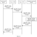
- FIG. 4 shows an example of a handover procedure in the CHO mechanism.
- a source base station configures two candidate target cells for UE, and the two candidate target cells are respectively managed by a candidate target base station 1 and a candidate target base station 2.
- the handover procedure may include the following steps: In step S401, the source base station delivers a measurement configuration to the UE. In step S402, the source base station correspondingly receives a measurement report reported by the UE. In step S403-a and step S404-a, the source base station and the candidate target base station 1 perform CHO preparation.
- the source base station may send a handover request message to the candidate target base station 1, and receive a handover request acknowledgment message from the candidate target base station 1, where the handover request acknowledgment message may include CHO configuration information of a candidate target cell 1.
- the source base station and the candidate target base station 2 perform CHO preparation.
- the source base station may send a handover request message to the candidate target base station 2, and receive a handover request acknowledgment message from the candidate target base station 2, where the handover request acknowledgment message may include CHO configuration information of a candidate target cell 2.
- the source base station may send an RRC message to the UE, where the RRC message includes the CHO configuration information respectively corresponding to the candidate target cell 1 and the candidate target cell 2.
- the UE may determine, based on the CHO configuration information of the candidate target cell 1 and the candidate target cell 2, whether respective CHO execution conditions of the candidate target cell 1 and the candidate target cell 2 are met, and use a cell that meets the CHO execution condition in the candidate target cell 1 and the candidate target cell 2 as a target cell. Subsequently, the UE may initiate random access to a base station to which the target cell belongs, to access the target cell. Assuming that the UE determines the candidate target cell 1 as the target cell, in step S407, the UE may perform a random access procedure with the candidate target base station 1 (namely, a target base station).
- the candidate target base station 1 namely, a target base station
- the UE may send an RRC reconfiguration complete message to the candidate target base station 1 (namely, the target base station).
- the candidate target base station may also be referred to as the target base station.
- FIG. 4 shows only an example of a CHO procedure, and the CHO procedure may have another variation. This is not limited in this application. The steps in FIG. 4 may be optional, and an execution sequence of the steps may be changed.
- the UE may determine, based on the CHO configuration information, whether the CHO execution condition is met.
- a CHO execution event type configured for the candidate target cell 1 is the event A3
- a trigger quantity configured for the candidate target cell 1 is the cell signal quality
- a corresponding threshold configured for the candidate target cell 1 is a first threshold.
- the signal quality may include one or more of the RSRP, the RSRQ, and the SINR.
- the signal quality may include the RSRP and the RSRQ, include the RSRP and the SINR, or include another parameter.
- the signal quality includes a plurality of parameters, it may be considered that each of the parameters is a separate trigger quantity.
- the signal quality includes the RSRP and the RSRQ, it may be considered that the RSRP is a trigger quantity, and the RSRQ is another trigger quantity.
- Different trigger quantities may correspond to a same first threshold or different first thresholds. This is not limited.
- the event A3 and two trigger quantities namely, the RSRP and the RSRQ
- a configured first threshold corresponding to the RSRP is E
- a configured first threshold corresponding to the RSRQ is F.
- the RSRP of the candidate target cell 1 is greater than RSRP of the serving cell by E
- the RSRQ of the candidate target cell 1 is greater than RSRQ of the serving cell by F
- the candidate target cell 1 may be determined as the target cell.
- a CHO execution event type configured for the candidate target cell 1 is the event A5
- a trigger quantity configured for the candidate target cell 1 is the cell signal quality
- corresponding thresholds configured for the candidate target cell 1 are a second threshold and a third threshold.
- the candidate target cell 1 meets the CHO execution condition, and the candidate target cell 1 may be determined as the target cell.
- CHO execution event types configured for the candidate target cell 1 are the event A3 and the event A5
- a trigger quantity configured for the event A3 is the RSRP
- a corresponding threshold configured for the event A3 is a first threshold
- a trigger quantity configured for the event A5 is the RSRQ
- corresponding thresholds configured for the event A5 are a second threshold and a third threshold.
- the candidate target cell 1 when the RSRP of the candidate target cell 1 is greater than RSRP of a serving cell by the first threshold, the RSRQ of the candidate target cell 1 is greater than the second threshold, and RSRQ of the serving cell is less than the third threshold, it may be considered that the candidate target cell 1 meets the CHO execution condition, and the candidate target cell 1 may be determined as the target cell.
- a handover failure may occur, and therefore a distinct gain is achieved by using the CHO mechanism in an NTN communication system.
- a network device may learn of an ephemeris, for example, a cell/base station that serves a terminal device at a specific geographical location or a cell/base station that serves the terminal device in a specific period of time. Therefore, a criterion for determining, based on time information and location information, whether a CHO execution condition is met may be introduced into the CHO mechanism in the NTN communication system.
- the CHO mechanism in the NTN communication system may include the following three types of CHO execution condition information:
- a network may configure at least one of the foregoing three types of CHO execution condition information as the CHO execution condition information.
- the CHO execution event type, the corresponding threshold, and the absolute time value may be configured as the CHO execution condition information.
- the terminal device may determine the candidate target cell as the target cell, and perform handover.
- the terminal device and/or the network device may perform a part or all of steps in embodiments of this application. These steps or operations are merely examples. In embodiments of this application, other operations or variations of various operations may be further performed. In addition, the steps may be performed in a sequence different from a sequence presented in embodiments of this application, and it is possible that not all operations in embodiments of this application need to be performed.
- a PLMN and an AMF entity are used as an example to describe the method in embodiments of this application.
- embodiments of this application are not limited to the PLMN and the AMF entity.
- the PLMN may be another communication network
- the AMF entity may be another entity or device that can implement a mobility management function or an entity or a device that implements a similar function in the communication network.
- FIG. 5 is a schematic flowchart of a communication method according to an embodiment of this application. The method includes the following steps.
- Step S501 A candidate target network device sends first information of a candidate target cell to a source network device, where the first information includes first PLMN information and/or first AMF information, and includes second PLMN information and/or second AMF information; the first information further includes first CHO configuration information and first area information that correspond to the first PLMN information and/or the first AMF information, and includes second CHO configuration information and second area information that correspond to the second PLMN information and/or the second AMF information; and the first area information indicates a first area covered by the candidate target cell, and the second area information indicates a second area covered by the candidate target cell.
- the source network device may receive the first information of the candidate target cell from the candidate target network device.
- content of the first information may be in the following plurality of possible cases:
- the following describes the method provided in this application by using an example in which the first information includes the first PLMN information and/or the first AMF information and includes the second PLMN information and/or the second AMF information.
- Step S502 The source network device sends the first information of the candidate target cell to a terminal device.
- the terminal device may receive the first information of the candidate target cell from the source network device.
- the candidate target cell is a cell that supports the first PLMN information and/or the first AMF information and supports the second PLMN information and/or the second AMF information
- the candidate target network device is a network device that manages the candidate target cell.
- the network device is a radio access network device on the ground.
- the network device is a radio access network device deployed on a satellite or the satellite. The satellite has a function of the radio access network device, in other words, the radio access network device is built in the satellite.
- the first PLMN information indicates a first PLMN
- the second PLMN information indicates a second PLMN.
- the first PLMN information corresponds to a first PLMN
- the second PLMN information corresponds to a second PLMN.
- the first PLMN information may include an identifier of the first PLMN
- the second PLMN information may include an identifier of the second PLMN.
- PLMN information in embodiments of this application may be indicated by an identifier (for example, a PLMN-identifier) of a PLMN.
- the first AMF information indicates a first AMF
- the second AMF information indicates a second AMF.
- the first AMF information corresponds to a first AMF
- the second AMF information corresponds to a second AMF
- the first AMF information may include an identifier of the first AMF, or include an identifier of the first AMF and the identifier of the first PLMN
- the second AMF information may include an identifier of the second AMF, or include an identifier of the second AMF and the identifier of the second PLMN.
- AMF information in embodiments of this application may be identified by an identifier (for example, an AMF-identifier) of an AMF or a combination of an identifier (for example, an AMF-identifier) of an AMF and an identifier (for example, a PLMN-identifier) of a PLMN.
- an identifier for example, an AMF-identifier
- a PLMN-identifier for example, a PLMN-identifier
- the candidate target cell may be a cell that can cover geographical areas of a plurality of countries or service areas of a plurality of operators.
- the candidate target cell may cover geographical areas of a country A (or an operator A) and a country B (or an operator B), where the country A (or the operator A) may correspond to the first PLMN or the first AMF, and the country B (or the operator B) may correspond to the second PLMN or the second AMF.
- a PLMN and an AMF that are deployed by the country A (or the operator A) and that manage the candidate target cell are respectively the first PLMN and the first AMF
- a PLMN and an AMF that are deployed by the country B (or the operator B) and that manage the candidate target cell are respectively the second PLMN and the second AMF.
- the candidate target cell covers the first area and the second area.
- the first area corresponds to the first PLMN and/or the first AMF
- the second area corresponds to the second PLMN and/or the second AMF.
- the first area information indicates a geographical location/range of the first area
- the second area information indicates a geographical location/range of the second area.
- the area information may be represented by one or more types of geographical location information in longitude information, latitude information, and height information, may be represented by one or more of longitude information, latitude information, and height information in combination with another parameter (for example, diameter/radius information), or may be represented by an area identifier (for example, an ID or an index).
- mapping relationship between an area identifier and a specific geographical location/range for example, a location/range represented by the longitude information, the latitude information, and the height information
- the mapping relationship may be agreed on in a protocol, or may be sent by a network device to the terminal device by using system information, an RRC message, or a layer 2 message.
- the area information may alternatively be represented in another form, for example, represented by a name or an identifier of an administrative region. This is not limited in this application.
- the candidate target network device may respectively configure CHO configuration information for different PLMNs and/or AMFs in the candidate target cell.
- the first CHO configuration information may correspond to the first PLMN and/or the first AMF
- the second CHO configuration information may correspond to the second PLMN and/or the second AMF.
- the first CHO configuration information may include first CHO execution condition information, and the first CHO execution condition information indicates a CHO execution condition (which may be referred to as a first CHO execution condition) that is of the candidate target cell and that corresponds to the first PLMN and/or the first AMF.
- the first CHO execution condition may be one or more of a signal quality-based CHO execution condition, a time/timer-based CHO execution condition, or a location-based CHO execution condition.
- the first CHO execution condition information may include one or more of signal quality-based execution condition information, time/timer-based execution condition information, or location-based execution condition information.
- the first CHO execution condition information refer to the foregoing related descriptions of the CHO execution condition information. Details are not described herein again.
- the second CHO configuration information may include second CHO execution condition information, and the second CHO execution condition information indicates a CHO execution condition (which may be referred to as a second CHO execution condition) that is of the candidate target cell and that corresponds to the second PLMN and/or the second AMF.
- the second CHO execution condition may be one or more of a signal quality-based CHO execution condition, a time/timer-based CHO execution condition, or a location-based CHO execution condition.
- the second CHO execution condition information may include one or more of signal quality-based execution condition information, time/timer-based execution condition information, or location-based execution condition information.
- content included in the first CHO configuration information and content included in the second CHO configuration information may be completely the same, partially the same, or completely different.
- RACH resource information included in the first CHO configuration information may be the same as or different from RACH resource information included in the second CHO configuration information.
- the RACH resource information may include a preamble (for example, a preamble index), a time-frequency resource, and the like. Therefore, that the two pieces of RACH resource information are different may mean that the preambles are different and/or the time-frequency resources are different.
- the first CHO execution condition information included in the first CHO configuration information may be the same as or different from the second CHO execution condition information included in the second CHO configuration information.
- key information/a key parameter that is included in the first CHO configuration information and that is used by the terminal device to access the candidate target cell may be the same as or different from key information/a key parameter that is included in the second CHO configuration information and that is used by the terminal device to access the candidate target cell.
- the source network device may perform CHO preparation processes with the candidate target network device respectively for the first PLMN and/or the first AMF of the candidate target cell and the second PLMN and/or the second AMF of the candidate target cell, and separately send, to the terminal device, content related to the first PLMN information and/or the first AMF information and content related to the second PLMN information and/or the second AMF information that are of the candidate target cell.
- the following describes in detail a CHO preparation process performed between the network device (for example, the source network device or the candidate target network device) and the first PLMN and/or the first AMF.
- the network device for example, the source network device or the candidate target network device
- a handover process may be referred to as an Xn interface-based CHO process.
- a source base station may directly send a handover request message to a candidate target base station.
- the candidate target base station may perform admission control/handover preparation based on the handover request message.
- the candidate target base station may perform processing such as resource configuration and CHO configuration information configuration. Further, in step S703, the candidate target base station may send a handover request acknowledgment message to the source base station, where the handover request acknowledgment message includes first PLMN information and/or first AMF information, and includes first CHO configuration information and first area information that correspond to the first PLMN information and/or the first AMF information, and the first area information indicates a first area covered by a candidate target cell.
- the source network device may indirectly exchange information with the candidate target network device through communication interfaces between a radio access network device and a core network device, in other words, perform CHO preparation through intermediate forwarding by the core network device.
- the core network device may be, for example, an AMF
- the communication interface between the radio access network device and the core network device may be, for example, an NG interface.
- a handover process may be referred to as an NG interface-based CHO process. For example, as shown in FIG.
- the source base station may send a first handover request message to a source AMF.
- the source AMF is an AMF that manages the source base station.
- the first handover request message may be a HO required message or have another name. This is not limited.
- the source AMF may send a second handover request message to a target AMF 1.
- the target AMF 1 is an AMF that manages the candidate target base station, and may be the foregoing first AMF or an AMF corresponding to the first PLMN.
- the second handover request message may be an Namf_Communication_CreatUEContext Request message or have another name. This is not limited.
- the target AMF 1 may send a third handover request message to the candidate target base station.
- the third handover request message may be an HO request message or have another name. This is not limited.
- the candidate target base station may perform admission control/handover preparation for handover of UE based on the third request message. If the candidate target base station determines to accept the handover request, the candidate target base station may perform processing such as resource configuration and CHO configuration information configuration.
- the candidate target base station may send a third handover response message to the target AMF 1.
- the third handover response message may be an HO request ACK message or have another name. This is not limited.
- the target AMF 1 may send a second handover response message to the source AMF.
- the second handover response message may be an Namf_Communication_CreatUEContext Response message or have another name. This is not limited.
- the source AMF after receiving the second handover response message, may send a first handover response message to the source base station.
- the first handover response message may be a HO command message or have another name. This is not limited.
- the third handover response message, the second handover response message, and the first handover response message may include first PLMN information and/or first AMF information, and include first CHO configuration information and first area information that correspond to the first PLMN and/or the first AMF, and the first area information indicates a first area covered by a candidate target cell.
- first PLMN information and/or first AMF information may include first CHO configuration information and first area information that correspond to the first PLMN and/or the first AMF, and the first area information indicates a first area covered by a candidate target cell.
- the source AMF and the target AMF 1 may be the same, or may be different. This is not limited.
- the source network device may send a first RRC message to the terminal device after obtaining, from the candidate target network device, the first PLMN information and/or the first AMF information of the candidate target cell and the first CHO configuration information and the first area information that correspond to the first PLMN and/or the first AMF, where the first RRC message includes the first PLMN information and/or the first AMF information of the candidate target cell, and includes the first CHO configuration information and the first area information that correspond to the first PLMN and/or the first AMF.
- a CHO preparation process performed between the network device for example, the source network device or the candidate target network device
- the second PLMN and/or the second AMF refer to the foregoing implementation of the CHO preparation process performed between the network device (for example, the source network device or the candidate target network device) and the first PLMN and/or the first AMF. Details are not described herein again.
- the source network device may send a second RRC message to the terminal device after obtaining, from the candidate target network device, the second PLMN information and/or the second AMF information of the candidate target cell and the second CHO configuration information and the second area information that correspond to the second PLMN and/or the second AMF, where the second RRC message includes the second PLMN information and/or the second AMF information of the candidate target cell, and includes the second CHO configuration information and the second area information that correspond to the second PLMN and/or the second AMF.
- the second RRC message and the foregoing first RRC message may be a same RRC message, or may be different RRC messages. This is not limited in this application.
- the source network device may send, to the terminal device by using one or more RRC messages, CHO configuration information, area information, and the like of the candidate target cell that correspond to each of the plurality of PLMNs and/or AMFs.
- this embodiment of this application is not limited to a case in which all the content included in the first information is sent as a whole by using one RRC message, and different PLMN information and/or AMF information, and the CHO configuration information and the area information that correspond to the PLMN information and/or the AMF information in the first information may be separately sent by using different RRC messages, to better conform to a concept that the candidate target network device separately manages and configures different PLMNs and/or AMFs supported by the candidate target network device.
- the source network device may configure one or more candidate target cells for the terminal device.
- one candidate target cell configured by the source network device for the terminal device is used as an example to describe a specific CHO mechanism applied when the candidate target cell is the NTN cell that supports the plurality of PLMNs and/or the plurality of AMFs.
- Another candidate target cell configured by the source network device for the terminal device may also be or may not be an NTN cell that covers geographical areas of a plurality of countries or service areas of a plurality of operators (namely, an NTN cell that supports a plurality of PLMNs and/or AMFs). This is not limited.
- the another candidate target cell configured by the source network device for the terminal device and the candidate target cell described as an example in this embodiment of this application may belong to a same network device, or may belong to different network devices. This is not limited in this application.
- the source network device may further obtain CHO configuration information of another candidate target cell from another candidate target network device, and send the CHO configuration information of the another candidate target cell to the terminal device by using a third RRC message.
- the source network device may send the third RRC message to the terminal device, where the third RRC message includes the CHO configuration information corresponding to the another candidate target cell.
- the another candidate target cell may also be or may not be a candidate cell that supports a plurality of PLMNs and/or AMFs. This is not limited.
- the third RRC message may further include PLMN information and/or AMF information, and area information that correspond to the CHO configuration information of the another candidate target cell.
- the third RRC message and the first RRC message may be a same RRC message, or may be different RRC messages. This is not limited.
- the third RRC message and the second RRC message may be a same RRC message, or may be different RRC messages. This is not limited either.
- Step S503 The terminal device determines a target cell, and target PLMN information and/or target AMF information based on the first information and an area in which the terminal device is currently located.
- the terminal device may determine the candidate target cell as the target cell, and determine the first PLMN information as the target PLMN information and/or determine the first AMF information as the target AMF information.
- the terminal device may determine the candidate target cell as the target cell, and determine the first PLMN information as the target PLMN information and/or determine the first AMF information as the target AMF information.
- the target PLMN information indicates a target PLMN, and the target AMF information indicates a target AMF.
- the target PLMN information corresponds to a target PLMN
- the target AMF information corresponds to a target AMF.
- the terminal device may further determine the first area as a target area, and the target PLMN information and/or the target AMF information are/is PLMN information and/or AMF information that correspond/corresponds to the target area.
- the terminal device may determine whether the first CHO execution condition in the first CHO configuration information and the second CHO execution condition in the second CHO configuration information are met, and determine the target cell, and the target PLMN and/or the target AMF with reference to a location of the terminal device (for example, the area in which the terminal device is currently located), a PLMN and/or an AMF that are/is supported by the terminal device, and the like.
- the first area may also be understood as an area, in one or more areas in the candidate target cell that meet the CHO execution condition, that overlaps an area to which the location of the terminal device belongs. Further, if the terminal device located in the first area can determine the cell that meets the CHO execution condition as the target cell, the terminal device is required to support the first PLMN and/or the first AMF that correspond/corresponds to the first area. The terminal device may also support the second AMF and/or the second PLMN. This is not limited. If the terminal device does not support the first AMF and/or the first PLMN, the cell cannot be determined as the target cell even if the cell meets the corresponding CHO execution condition.
- the terminal device may determine the candidate target cell as the target cell, and determine the first PLMN as the target PLMN and/or determine the first AMF as the target AMF.
- the terminal device may determine the candidate target cell as the target cell, and determine the first PLMN as the target PLMN and/or determine the first AMF as the target AMF.
- the first area is merely an example. If the second CHO execution condition in the second CHO configuration information is met, the terminal device is currently located in the second area, and the terminal device supports the second PLMN and/or the second AMF that correspond/corresponds to the second area, the terminal device may determine the candidate target cell as the target cell, and determine the second PLMN as the target PLMN and/or determine the second AMF as the target AMF.
- the second area may be determined as the target area. In this case, for related processing for the second area, refer to the foregoing related descriptions of the first area. Details are not described again.
- the terminal device may determine, as the target cell based on the current location of the terminal device, a candidate target cell managed by a PLMN and/or an AMF that supports/allows access of the terminal device at the location (or in an area to which the location belongs).
- UE 1 supports a PLMN 1 and a PLMN 2. If the UE 1 determines, after performing determining on a CHO execution condition, that a cell 1 corresponding to first CHO configuration information meets the CHO execution condition, and a cell 1 corresponding to second CHO configuration information also meets CHO execution condition, the UE 1 may determine, based on a geographical location of the UE 1, that the UE 1 is located in a first area, where the first area corresponds to the PLMN 1 and the first CHO configuration information.
- the UE 1 may determine the cell 1 corresponding to the first CHO configuration information as a target cell, determine the PLMN 1 as a target PLMN, and determine the AMF 1 as a target AMF.
- the UE 1 may further determine the first area as a target area.
- UE 2 supports a PLMN 1 and a PLMN 2. If the UE 2 determines, after performing determining on a CHO execution condition, that a cell 1 corresponding to second CHO configuration information meets CHO execution condition, the UE 2 may determine, based on a geographical location of the UE 2, that the UE 2 is located in a second area. Because a PLMN and/or an AMF supporting/allowing access of the UE 2 in the second area are/is the PLMN 2 and/or an AMF 2, the UE 2 may determine the cell 1 corresponding to the second CHO configuration information as a target cell, determine the PLMN 2 as a target PLMN, and determine the AMF 2 as a target AMF.
- UE 2 supports a PLMN 1 and a PLMN 2. If the UE 2 determines, after performing determining on a CHO execution condition, that a cell 1 corresponding to first CHO configuration information meets CHO execution condition, and a cell 1 corresponding to second CHO configuration information also meets the CHO execution condition information, the UE 2 may determine, based on a geographical location of the UE 2, that the UE 2 is located in a second area.
- the UE 2 may determine the cell 1 corresponding to the second CHO configuration information as a target cell, determine the PLMN 2 as a target PLMN, and determine the AMF 2 as a target AMF.
- the UE 2 may further determine the second area as a target area.
- Step S504 The terminal device sends a first message to a target network device, where the first message indicates that the terminal device has been successfully handed over to the target cell, and includes the target PLMN information and/or the target AMF information.
- the target network device may receive the first message from the terminal device.
- the network device that manages the candidate target cell is referred to as the candidate target network device, in other words, a network device to which the candidate target cell belongs is the candidate target network device.
- the candidate target network device may be referred to as the target network device after the terminal device determines the candidate target cell as the target cell.
- the target network device is a network device to which the candidate target cell determined as the target cell belongs.
- the target cell supports the first PLMN and/or the first AMF, and supports the second PLMN and/or the second AMF.
- the target cell accesses the first PLMN and/or the first AMF, and accesses the second PLMN and/or the second AMF;
- the target cell belongs to the first PLMN, core network devices connected to the target cell include the first AMF, the target cell also belongs to the second PLMN, and the core network devices connected to the target cell include the second AMF; or the target cell is managed by the first PLMN and/or the first AMF, and is managed by the second PLMN and/or the second AMF.
- the target PLMN information and/or the target AMF information may be the first PLMN information and/or the first AMF information, or may be the second PLMN information and/or the second AMF information.
- the first message may further include one or more of the following information: identification information (for example, a PCI and/or a C-RNTI, or a CGI) of the target cell, index information corresponding to the target cell (for example, a measurement identifier (measID) corresponding to the target cell and/or a CHO configuration identifier (CondReconfigId) corresponding to the target cell), information other than the index information and the identification information that correspond to the target cell in CHO configuration information corresponding to the target PLMN or the target AMF, and area information corresponding to the target PLMN or the target AMF.
- identification information for example, a PCI and/or a C-RNTI, or a CGI
- index information corresponding to the target cell for example, a measurement identifier (measID) corresponding to the target cell and/or a CHO configuration identifier (CondReconfigId) corresponding to the target cell
- a first cell is the candidate target cell, and may be one of the plurality of candidate target cells configured by the source network device for the terminal device.
- the terminal device may send the first message to a network device (namely, the target network device) to which the first cell belongs.
- the first message includes at least one of the following: the first PLMN information, the first AMF information, identification information of the first cell (for example, a PCI and/or a C-RNTI of the first cell, or a CGI of the first cell), and one or more pieces of information in first CHO configuration information of the first cell.
- the first CHO configuration information includes index information (for example, a measurement identifier measID and/or a CHO configuration identifier CondReconfigId) corresponding to the first cell and area information corresponding to the first PLMN information or the first AMF information.
- the network device to which the first cell belongs may be referred to as the candidate target network device before the first cell is determined as the target cell, and may be referred to as the target network device after the first cell is determined as the target cell.
- the first message may be a handover acknowledge (for example, HO confirm) message, or may have another name. This is not limited in this application.
- the key information/key parameter that is included in the first CHO configuration information and that is for accessing the candidate target cell may be the same as or different from the key information/key parameter that is included in the second CHO configuration information and that is for accessing the candidate target cell
- the RACH resource information included in the first CHO configuration information may be the same as or different from the RACH resource information included in the second CHO configuration information.
- the terminal device may encrypt the first message by using a first key corresponding to the first CHO configuration information when sending the first message to the network device (namely, the target network device) to which the candidate target cell belongs.
- the first CHO configuration information may include first key information, and the terminal device may determine the first key based on the first key information.
- the target network device may determine, based on a RACH resource used by the terminal device to initiate random access, that the first CHO configuration information is selected by the terminal device, in other words, determine that the target PLMN selected by the terminal device is the first PLMN or the target AMF selected by the terminal device is the first AMF, and then decrypt the first message by using the corresponding first key, where the first key may be a key indicated by the first key information in the first CHO configuration information.
- the target network device When the RACH resource information included in the first CHO configuration information is the same as the RACH resource information included in the second CHO configuration information, the target network device cannot determine, based on a RACH resource used by the terminal device to initiate random access, a key used by the terminal device. Therefore, in this scenario, to enable the target network device to correctly receive/parse the first message, the terminal device may send two first messages to the target network device, where one of the first messages is encrypted by using a first key corresponding to the first CHO configuration information, and the other first message is encrypted by using a second key corresponding to the second CHO configuration information. This can effectively improve security of transmitting the first message.
- the first CHO configuration information may include first key information
- the second CHO configuration information may include second key information
- the terminal device may determine the first key based on the first key information, and determine the second key based on the second key information.
- the target network device may decrypt the two first messages by using the first key and/or the second key. It can be learned that in this case, the target network device can decrypt the first message regardless of whether the terminal device encrypts the first message by using the first key or the second key, to obtain the information in the first message.
- the terminal device may also encrypt the first message by using a key corresponding to the first CHO configuration information or a key corresponding to the second CHO configuration information.
- the different CHO configuration information includes the same RACH resource information
- the target network device cannot determine, based on the RACH resource information used by the terminal device to perform random access, the key for encrypting the first message, because the terminal device encrypts the first message by using the key corresponding to the first CHO configuration information or the second CHO configuration information, the target network device may attempt to decrypt the first message by using the keys corresponding to the different CHO configuration information (namely, the key corresponding to the first CHO configuration information and the key corresponding to the second CHO configuration information), to successfully decrypt the first message.
- the target network device may send a second message to the target AMF after receiving the first message from the terminal device, where the second message notifies the target AMF that the terminal device has completed the handover.
- the second message may be a handover notify (HO notify) message, or may have another name. This is not limited in this application.
- the target AMF herein may be the first AMF.
- the target cell or the target network device may be managed by a plurality of AMFs (for example, the first AMF and the second AMF described above). Therefore, after receiving the first message from the terminal device, the target network device may determine, based on the first message, the target AMF selected by the terminal device. If the target network device determines that the target AMF is the first AMF, the target network device may send a third message to the second AMF, where the third message indicates the second AMF to release a connection established by the second AMF for the terminal device, and the connection is a connection between the second AMF and the target network device that is established by the second AMF for the terminal device.
- the third message may include a connection release cause value.
- connection release cause value indicates that a connection release cause is a location exception or AMF unavailability.
- the second AMF is an AMF that is configured to manage the target network device but that does not allow access of the terminal device, in other words, is a non-target AMF.
- the terminal device may further release the second PLMN information and/or the second AMF information, and release the second CHO configuration information and the second area information.
- the target network device may further send a fourth message to the terminal device, where the fourth message indicates the terminal device to release the second PLMN information and/or the second AMF information and release the second CHO configuration information and the second area information that correspond to the second PLMN information and/or the second AMF information.
- the terminal device may release the second PLMN information and/or the second AMF information, and release the second CHO configuration information and the second area information.
- the terminal device can delete or release unnecessary configuration information, resources, or the like in time, to effectively improve resource utilization.
- the first AMF and the second AMF are used as an example for description.
- the target network device may send a third message to each AMF other than the target AMF, to indicate these AMFs to release connections established for the terminal device.
- the foregoing technical solution provides a CHO mechanism applied when a cell that covers geographical areas of a plurality of countries or service areas of a plurality of operators is configured as the candidate target cell of the terminal device.
- the terminal device can determine the target cell, and the target PLMN and/or the target AMF from the configured candidate target cell based on cells that meet the CHO execution condition, the location of the terminal device, and the PLMN and/or the AMF that are/is supported by the terminal device. Therefore, the foregoing technical solution can effectively improve handover reliability.
- FIG. 9 shows a specific example of the communication method according to an embodiment of this application.
- an S-gNB represents a source base station
- an S-AMF represents a source AMF
- a T-gNB represents a target base station, and may also be referred to as a candidate T-gNB
- a T-AMF 1 represents a target AMF 1
- a T-AMF2 represents a target AMF 2.
- the S-gNB may configure, as a candidate target cell of UE, a cell served by the T-gNB.
- the T-AMF 1 is an AMF that manages a virtual cell, in the candidate target cell, that corresponds to a PLMN 1
- the T-AMF 2 is an AMF that manages a virtual cell, in the candidate target cell, that corresponds to a PLMN 2
- the candidate target cell is a cell that supports the PLMN 1 and the PLMN 2, or is a cell that supports the T-AMF 1 and the T-AMF 2.
- a core network device that may be connected to the candidate target cell is the T-AMF 1 and/or the T-AMF 2
- the candidate target cell belongs to the PLMN 1 and/or the PLMN 2.
- the candidate target cell is managed by the T-AMF 1/T-AMF 2/PLMN 1/PLMN 2.
- the S-gNB performs CHO preparation with the T-gNB through the S-AMF and the T-AMF 1.
- the S-gNB performs CHO preparation with the T-gNB through the S-AMF and the T-AMF 2.
- the S-gNB may send first CHO configuration information to the UE, where the first CHO configuration information includes first CHO execution condition information.
- the S-gNB may send second CHO configuration information to the UE, where the second CHO configuration information includes second CHO execution condition information.
- the first CHO configuration information and the second CHO configuration information may be sent by using a same RRC message or different RRC messages. This is not limited.
- the UE may determine, based on the first CHO configuration information and the second CHO configuration information, whether CHO execution conditions are met.
- the UE may determine the candidate target cell as a target cell, determine the PLMN 1 as a target PLMN, and determine the T-AMF 1 as a target AMF. Further, in step S904, the UE may send a handover acknowledge message to the T-gNB, where the handover notification message notifies the T-gNB that the UE has been successfully handed over to the target cell, and the handover acknowledge message includes target PLMN information and/or target AMF information (namely, information about the PLMN 1 and/or information about the T-AMF 1).
- the T-gNB may send a handover notify message to the T-AMF 1, where the handover notify message notifies the T-AMF 1 that the UE has completed the handover.
- the T-gNB may send a connection release message to the T-AMF 2 (namely, a non-target AMF), where the connection release message indicates the T-AMF 2 to release a connection between the T-AMF 2 and the T-gNB that is established for the UE, and includes a connection release cause, for example, a location exception, unavailability of the T-AMF 2, or mismatching between the T-AMF 2 and a location of the UE.
- the T-AMF 1 and the S-AMF may be the same or different, and the T-AMF 2 and the S-AMF may be the same or different. This is not limited. It should be noted that the T-AMF 1 is different from the T-AMF 2.
- the S-gNB and the T-gNB may be a same base station, or may be different base stations. This is not limited in this embodiment of this application.
- the target network device in this embodiment of this application may be in a separated form including a CU node and a DU node.
- the CU node serving as a message/information receiver may send a part or all of received information to the DU node.
- a target CU node may send a part or all of the information in the received first message to a target DU node.
- the target CU node is the CU node of the target network device
- the target DU node is the DU node of the target network device.
- a CU-CP node serving as the message/information receiver may send a part or all of the received information to a CU-UP node.
- a target CU-CP node may send a part or all of the information included the received first message to a target CU-UP node.
- the terminal device in this embodiment of this application may be in a separated form including a CU node and a DU node.
- the CU node in the terminal device may also be divided into a control plane (CU-CP) and a user plane (CU-UP).
- CU-CP control plane
- CU-UP user plane
- the terminal device is in the separated form including the CU node and the DU node, or further, the CU node in the terminal device includes the control plane (CU-CP) and the user plane (CU-UP)
- the CU node (or a CU-CP node) serving as a message/information receiver may send a part or all of received information to the DU node (or a CU-UP node).
- CU-CP control plane
- CU-UP user plane
- the CU node (or a CU-CP node) serving as a message/information receiver may send a part or all of received information to the DU node (or a CU-UP
- FIG. 10 is a schematic diagram of a structure of the communication apparatus according to this embodiment of this application.
- the communication apparatus 1000 includes a transceiver module 1010 and a processing module 1020.
- the communication apparatus may be configured to implement a function of the terminal device in any one of the foregoing method embodiments.
- the communication apparatus may be a terminal device, for example, a handheld terminal device or a vehicle-mounted terminal device.
- the communication apparatus may be a chip or a circuit included in a terminal device or an apparatus, for example, various types of vehicles, including a terminal device.
- the transceiver module 1010 is configured to receive first information of a candidate target cell from a source network device, where the first information includes first PLMN information and/or first AMF information, and includes second PLMN information and/or second AMF information; the first information further includes first CHO configuration information and first area information that correspond to the first PLMN information and/or the first AMF information, and includes second CHO configuration information and second area information that correspond to the second PLMN information and/or the second AMF information; and the first area information indicates a first area covered by the candidate target cell, and the second area information indicates a second area covered by the candidate target cell.
- the processing module 1020 is configured to determine a target cell, and target PLMN information and/or target AMF information based on the first information and an area in which the communication apparatus is currently located.
- the processing module 1020 is specifically configured to: if a first CHO execution condition in the first CHO configuration information is met, and the terminal device is currently located in the first area, the terminal device may determine the candidate target cell as the target cell, and determine the first PLMN information as the target PLMN information and/or determine the first AMF information as the target AMF information.
- the processing module 1020 is specifically configured to: if the first CHO execution condition in the first CHO configuration information and a second CHO execution condition in the second CHO configuration information are both met, and the terminal device is currently located in the first area, the terminal device may determine the candidate target cell as the target cell, and determine the first PLMN information as the target PLMN information and/or determine the first AMF information as the target AMF information.
- the transceiver module 1010 is further configured to send a first message to a target network device, where the first message indicates that the terminal device has been successfully handed over to the target cell, and includes the target PLMN information and/or the target AMF information, and the target network device is a network device that manages the target cell.
- the first message further includes identification information of the target cell and/or index information corresponding to the target cell.
- the first message may be encrypted by using a first key corresponding to the first CHO configuration information.
- the transceiver module 1010 is specifically configured to send two first messages to the target network device, where one of the first messages is encrypted by using a first key corresponding to the first CHO configuration information, and the other first message is encrypted by using a second key corresponding to the second CHO configuration information.
- the first CHO configuration information includes first CHO execution condition information, and the first CHO execution condition information indicates a first CHO execution condition that is of the candidate target cell and that corresponds to the first PLMN information and/or the first AMF information, and includes one or more of signal quality-based execution condition information, time/timer-based execution condition information, or location-based execution condition information;
- the first PLMN information includes an identifier of a first PLMN, and the first AMF information includes an identifier of a first AMF, or includes an identifier of a first AMF and the identifier of the first PLMN;
- the second CHO configuration information includes second CHO execution condition information, and the second CHO execution condition information indicates a second CHO execution condition that is of the candidate target cell and that corresponds to the second PLMN information and/or the second AMF information, and includes one or more of signal quality-based execution condition information, time/timer-based execution condition information, or location-based execution condition information;
- the second PLMN information includes an an
- the processing module 1020 is further configured to: release the second PLMN information and/or the second AMF information, and release the second CHO configuration information and the second area information.
- the communication apparatus may be configured to implement a function of the network device (for example, the source network device or the target network device (also referred to as the candidate target network device)) in any one of the foregoing method embodiments.
- the communication apparatus may be a network device or a chip or a circuit included in the network device.
- the transceiver module 1010 is configured to receive first information of a candidate target cell from a candidate target network device, where the first information includes first PLMN information and/or first AMF information, and includes second PLMN information and/or second AMF information; the first information further includes first CHO configuration information and first area information that correspond to the first PLMN information and/or the first AMF information, and includes second CHO configuration information and second area information that correspond to the second PLMN information and/or the second AMF information; and the first area information indicates a first area covered by the candidate target cell, and the second area information indicates a second area covered by the candidate target cell.
- the processing module 1020 is configured to send the first information of the candidate target cell to a terminal device through the transceiver module 1020.
- the first CHO configuration information includes first CHO execution condition information, and the first CHO execution condition information indicates a first CHO execution condition that is of the candidate target cell and that corresponds to the first PLMN information and/or the first AMF information, and includes one or more of signal quality-based execution condition information, time/timer-based execution condition information, or location-based execution condition information;
- the first PLMN information includes an identifier of a first PLMN, and the first AMF information includes an identifier of a first AMF, or includes an identifier of a first AMF and the identifier of the first PLMN;
- the second CHO configuration information includes second CHO execution condition information, and the second CHO execution condition information indicates a second CHO execution condition that is of the candidate target cell and that corresponds to the second PLMN information and/or the second AMF information, and includes one or more of signal quality-based execution condition information, time/timer-based execution condition information, or location-based execution condition information;
- the second PLMN information includes an an
- the transceiver module 1010 is configured to send first information of a candidate target cell to a source network device, where the first information includes first PLMN information and/or first AMF information, and includes second PLMN information and/or second AMF information; the first information further includes first CHO configuration information and first area information that correspond to the first PLMN information and/or the first AMF information, and includes second CHO configuration information and second area information that correspond to the second PLMN information and/or the second AMF information; and the first area information indicates a first area covered by the candidate target cell, and the second area information indicates a second area covered by the candidate target cell.
- the processing module 1020 is configured to receive a first message from a terminal device through the transceiver module 1010 if the terminal device determines the candidate target cell as a target cell, where the first message indicates that the terminal device has been successfully handed over to the target cell, and includes target PLMN information and/or target AMF information, and the target PLMN information and/or the target AMF information are/is the first PLMN information and/or the first AMF information, or are/is the second PLMN information and/or the second AMF information.
- the processing module 1020 is specifically configured to: determine, based on RACH resource information used by the terminal device to initiate a random access procedure, a first key for decrypting the first message, and decrypt the first message by using the first key.
- the transceiver module 1010 is specifically configured to receive two first messages from the terminal device.
- the processing module 1020 is specifically configured to decrypt the two first messages by using a first key and/or a second key, where the first key is a key corresponding to the first CHO configuration information, and the second key is a key corresponding to the second CHO configuration information.
- the transceiver module 1010 is further configured to send a second message to a target AMF corresponding to the target AMF information, where the second message indicates, to the target AMF, that the terminal device has completed the handover.
- the transceiver module 1010 is further configured to send a third message to an AMF corresponding to AMF information other than the target AMF information in the first AMF information and the second AMF information, where the third message indicates the another AMF to release a connection established for the terminal device.
- the third message includes a connection release cause value
- the connection release cause value is a location exception or AMF unavailability
- the first CHO configuration information includes first CHO execution condition information, and the first CHO execution condition information indicates a CHO execution condition that is of the candidate target cell and that corresponds to the first PLMN information and/or the first AMF information, and includes one or more of signal quality-based execution condition information, time/timer-based execution condition information, or location-based execution condition information;
- the first PLMN information includes an identifier of a first PLMN, and the first AMF information includes an identifier of a first AMF, or includes an identifier of a first AMF and the identifier of the first PLMN;
- the second CHO configuration information includes second CHO execution condition information, and the second CHO execution condition information indicates a CHO execution condition that is of the target cell and that corresponds to the second PLMN information and/or the second AMF information, and includes one or more of signal quality-based execution condition information, time/timer-based execution condition information, or location-based execution condition information; and the second PLMN information includes an identifier of
- the processing module 1020 in the communication apparatus may be implemented by at least one processor or processor-related circuit component, and the transceiver module 1010 may be implemented by at least one transceiver, transceiver-related circuit component, or communication interface. Operations and/or functions of the modules in the communication apparatus are respectively for implementing corresponding procedures of the method shown in FIG. 5 , FIG. 7 , FIG. 8 , or FIG. 9 . For brevity, details are not described herein again.
- the communication apparatus may further include a storage module.
- the storage module may be configured to store data and/or instructions.
- the transceiver module 1010 and/or the processing module 1020 may read the data and/or the instructions in the storage module, to enable the communication apparatus to implement the corresponding method.
- the storage module may be implemented, for example, by using at least one memory.
- the storage module, the processing module, and the transceiver module may exist separately. Alternatively, all or a part of the modules may be integrated. For example, the storage module and the processing module are integrated, or the processing module and the transceiver module are integrated.
- FIG. 11 is a schematic diagram of another structure of a communication apparatus according to an embodiment of this application.
- the communication apparatus may be configured to implement a corresponding function of the terminal device in the foregoing method embodiments, and for example, may be a terminal device or an apparatus that can support the terminal device in implementing the corresponding function in the foregoing method embodiments.
- the communication apparatus may be configured to implement a corresponding function of the source network device or the target network device in the foregoing method embodiments, and for example, may be a source network device or a target network device, or may be an apparatus that can support the source network device or the target network device in implementing the corresponding function in the foregoing method embodiments.
- the communication apparatus 1100 may include a processor 1101, a communication interface 1102, and a memory 1103.
- the communication interface 1102 is configured to communicate with another device through a transmission medium.
- the communication interface 1102 may be a transceiver, or may be an interface circuit, for example, a transceiver circuit or a transceiver chip.
- the memory 1103 is configured to store program instructions and/or data, and the processor 1101 is configured to execute the program instructions stored in the memory 1103, to implement the methods in the foregoing method embodiments.
- the memory 1103 and the processor 1101 are coupled, and the coupling is indirect coupling or a communication connection between apparatuses, units, or modules in an electrical form, a mechanical form, or another form, and is for information exchange between the apparatuses, the units, or the modules.
- the communication interface 1102 may be specifically configured to perform an action of the transceiver module 1010, and the processor 1101 may be specifically configured to perform an action of the processing module 1020. Details are not described herein again in this application.
- a specific connection medium between the communication interface 1102, the processor 1101, and the memory 1103 is not limited.
- the memory 1103, the processor 1101, and the communication interface 1102 are connected through a bus 1104 in FIG. 11 , and the bus is represented by a thick line in FIG. 11 .
- a manner of connecting other components is merely an example for description, and is not limited thereto.
- the bus may be classified into an address bus, a data bus, a control bus, and the like. For ease of representation, only one thick line is used to represent the bus in FIG. 11 , but this does not mean that there is only one bus or only one type of bus.
- FIG. 12 is a simplified schematic diagram of a structure of a communication apparatus.
- the communication apparatus may be specifically a terminal device, and is configured to implement a function of the terminal device in any one of the foregoing method embodiments.
- a mobile phone is used as an example of the terminal device.
- the terminal device includes a processor, and may further include a memory.
- the terminal device may further include a radio frequency circuit, an antenna, an input/output apparatus, and the like.
- the processor is mainly configured to: process a communication protocol and communication data, control the terminal device, execute a software program, process data of the software program, and so on.
- the memory is mainly configured to store the software program and the data.
- the radio frequency circuit is mainly configured to: perform conversion between a baseband signal and a radio frequency signal, and process the radio frequency signal.
- the antenna is mainly configured to send and receive the radio frequency signal in an electromagnetic wave form.
- the input/output apparatus for example, a touchscreen, a display, or a keyboard, is mainly configured to: receive data input by a user, and output data to the user. It should be noted that some types of terminal devices may have no input/output apparatus.
- the processor When data needs to be sent, after performing baseband processing on the to-be-sent data, the processor outputs a baseband signal to the radio frequency circuit.
- the radio frequency circuit performs radio frequency processing on the baseband signal and then sends a radio frequency signal to the outside in the electromagnetic wave form through the antenna.
- the radio frequency circuit receives a radio frequency signal through the antenna, converts the radio frequency signal into a baseband signal, and outputs the baseband signal to the processor.
- the processor converts the baseband signal into data, and processes the data.
- FIG. 12 shows only one memory and one processor. In an actual terminal device product, there may be one or more processors and one or more memories.
- the memory may also be referred to as a storage medium, a storage device, or the like.
- the memory and the processor may be separately disposed, or may be integrated together. This is not limited in this embodiment of this application.
- the antenna and the radio frequency circuit that have receiving and sending functions may be considered as a transceiver unit of the terminal device, and the processor that has a processing function may be considered as a processing unit of the terminal device.
- the terminal device includes a transceiver unit 1210 and a processing unit 1220.
- the transceiver unit may also be referred to as a transceiver, a transceiver apparatus, or the like.
- the processing unit may also be referred to as a processor, a processing board, a processing module, a processing apparatus, or the like.
- a component that is in the transceiver unit 1210 and that is configured to implement the receiving function may be considered as a receiving unit
- a component that is in the transceiver unit 1210 and that is configured to implement the sending function may be considered as a sending unit.
- the transceiver unit 1210 includes the receiving unit and the sending unit.
- the transceiver unit may also be sometimes referred to as a transceiver, a transceiver circuit, or the like.
- the receiving unit sometimes may also be sometimes referred to as a receiver, a receive circuit, or the like.
- the sending unit may also be sometimes referred to as a transmitter, a transmit circuit, or the like.
- transceiver unit 1210 is configured to perform a sending operation and a receiving operation on a terminal device side in the foregoing method embodiments
- processing unit 1220 is configured to perform an operation other than the sending operation and the receiving operation of the terminal device in the foregoing method embodiments.
- FIG. 13 is another simplified schematic diagram of a structure of a communication apparatus.
- the communication apparatus may be specifically a network device, for example, a base station, and is configured to implement a function of the network device (for example, the source network device, the target network device, or the candidate target network device) in any one of the foregoing method embodiments.
- the network device 1300 includes one or more DUs 1301 and one or more CUs 1302.
- the DU 1301 may include at least one antenna 13011, at least one radio frequency unit 13012, at least one processor 13013, and at least one memory 13014.
- the DU 1301 is mainly configured to send and receive a radio frequency signal, perform conversion between the radio frequency signal and a baseband signal, and perform some baseband processing.
- the CU 1302 may include at least one processor 13022 and at least one memory 13021.
- the CU 1302 is mainly configured to: perform baseband processing, control the base station, and so on.
- the CU 1302 is a control center of the base station, and may also be referred to as a processing unit.
- the CU 1302 may be configured to control the base station to perform corresponding operations or steps of the source network device or the target network device in the method shown in FIG. 5 , FIG. 7 , FIG. 8 , or FIG. 9 .
- the CU 1302 and the DU 1301 may communicate with each other through an interface.
- a control plane (control plane, CP) interface may be an Fs-C interface, for example, an F1-C interface
- a user plane (user plane, UP) interface may be an Fs-U interface, for example, an F1-U interface.
- the DU 1301 and the CU 1302 may be physically disposed together, or may be physically disposed separately (in other words, the base station is a distributed base station). This is not limited.
- the baseband processing on the CU and the DU may be divided based on protocol layers of a wireless network.
- functions of a PDCP layer and a layer above the PDCP layer are configured on the CU, and functions of protocol layers (for example, an RLC layer and a MAC layer) below the PDCP layer are configured on the DU.
- the CU implements functions of an RRC layer and a PDCP layer
- the DU implements functions of an RLC layer, a MAC layer, and a physical (physical, PHY) layer.
- the base station 1300 may include one or more remote units (RUs), one or more DUs, and one or more CUs.
- the DU may include at least one processor 13013 and at least one memory 13014
- the RU may include at least one antenna 13011 and at least one radio frequency unit 13012
- the CU may include at least one processor 13022 and at least one memory 13021.
- the CU 1302 may include one or more boards.
- a plurality of boards may jointly support a radio access network (for example, a 5G network) of a single access standard, or may separately support radio access networks (such as an LTE network, a 5G network, or another network) of different access standards.
- the memory 13021 and the processor 13022 may serve one or more boards. In other words, a memory and a processor may be disposed on each board. Alternatively, a plurality of boards may share a same memory and a same processor. In addition, a necessary circuit may be further configured on each board.
- the DU 1301 may include one or more boards.
- a plurality of boards may jointly support a radio access network (for example, a 5G network) of a single access standard, or may separately support radio access networks (such as an LTE network, a 5G network, or another network) of different access standards.
- the memory 13014 and the processor 13013 may serve one or more boards. In other words, a memory and a processor may be disposed on each board. Alternatively, a plurality of boards may share a same memory and a same processor. In addition, a necessary circuit may be further configured on each board.
- An embodiment of this application further provides a chip system, including a processor, where the processor is coupled to a memory.
- the memory is configured to store a program or instructions.
- the chip system is enabled to implement the method corresponding to the terminal device or the method corresponding to the network device (for example, the source network device or the target network device) in any one of the foregoing method embodiments.
- the processor may be implemented by hardware, or may be implemented by software.
- the processor may be a logic circuit, an integrated circuit, or the like.
- the processor may be a general-purpose processor, and is implemented by reading software code stored in the memory.
- the memory and the processor may be integrated together, or may be separately disposed.
- the memory may be a non-transitory memory, for example, a read-only memory ROM.
- the memory and the processor may be integrated into a same chip, or may be separately disposed on different chips.
- a type of the memory and a manner of disposing the memory and the processor are not specifically limited in this application.
- the chip system may be a field programmable gate array (field programmable gate array, FPGA), an application-specific integrated circuit (application-specific integrated circuit, ASIC), a system on a chip (system on a chip, SoC), a central processing unit (central processing unit, CPU), a network processor (network processor, NP), a digital signal processor (digital signal processor, DSP), a microcontroller unit (microcontroller unit, MCU), a programmable logic device (programmable logic device, PLD), or another integrated chip.
- field programmable gate array field programmable gate array
- ASIC application-specific integrated circuit
- SoC system on a chip
- CPU central processing unit
- CPU central processing unit
- network processor network processor
- NP digital signal processor
- DSP digital signal processor
- microcontroller unit microcontroller unit
- MCU programmable logic device
- PLD programmable logic device
- An embodiment of this application further provides a computer-readable storage medium.
- the computer storage medium stores computer-readable instructions.
- the computer When a computer reads and executes the computer-readable instructions, the computer is enabled to perform the method in any one of the foregoing method embodiments.
- An embodiment of this application further provides a computer program product.
- a computer reads and executes the computer program product, the computer is enabled to perform the method in any one of the foregoing method embodiments.
- An embodiment of this application further provides a communication system.
- the communication system includes a source network device and a target network device.
- the communication system may further include at least one terminal device.
- the target network device may be a candidate target network device configured by the source network device.
- the communication system may further include one or more other candidate target network devices configured by the source network device.
- the communication system may further include a core network device.
- the processor in embodiments of this application may be a CPU, or may be another general-purpose processor, a DSP, an ASIC, an FPGA or another programmable logic device, a discrete gate or transistor logic device, a discrete hardware component, or the like.
- the general-purpose processor may be a microprocessor, or the processor may be any conventional processor or the like.
- the memory in embodiments of this application may be a volatile memory or a nonvolatile memory, or may include a volatile memory and a nonvolatile memory.
- the nonvolatile memory may be a read-only memory (read-only memory, ROM), a programmable read-only memory (programmable ROM, PROM), an erasable programmable read-only memory (erasable PROM, EPROM), an electrically erasable programmable read-only memory (electrically EPROM, EEPROM), or a flash memory.
- the volatile memory may be a random access memory (random access memory, RAM), used as an external cache.
- RAMs may be used, for example, a static random access memory (static RAM, SRAM), a dynamic random access memory (dynamic RAM, DRAM), a synchronous dynamic random access memory (synchronous DRAM, SDRAM), a double data rate synchronous dynamic random access memory (double data rate SDRAM, DDR SDRAM), an enhanced synchronous dynamic random access memory (enhanced SDRAM, ESDRAM), a synchlink dynamic random access memory (synchlink DRAM, SLDRAM), and a direct rambus random access memory (direct rambus RAM, DR RAM).
- static random access memory static random access memory
- DRAM dynamic random access memory
- DRAM dynamic random access memory
- SDRAM synchronous dynamic random access memory
- double data rate SDRAM double data rate SDRAM
- DDR SDRAM double data rate SDRAM
- ESDRAM enhanced synchronous dynamic random access memory
- synchlink dynamic random access memory synchlink dynamic random access memory
- direct rambus RAM direct rambus RAM, DR RAM
- the processor is a general-purpose processor, a DSP, an ASIC, an FPGA or another programmable logic device, a discrete gate or a transistor logic device, or a discrete hardware component
- the memory is integrated into the processor.
- the memory described in this specification aims to include but is not limited to these memories and any memory of another appropriate type.
- the disclosed system, apparatus, and method may be implemented in other manners.
- the foregoing apparatus embodiments are merely examples.
- division into the units is merely logical function division and may be other division during actual implementation.
- a plurality of units or components may be combined or integrated into another system, or some features may be ignored or not performed.
- the displayed or discussed mutual couplings or direct couplings or communication connections may be implemented by using some interfaces.
- the indirect couplings or communication connections between the apparatuses or units may be implemented in an electrical form, a mechanical form, or other forms.
- the units described as separate parts may or may not be physically separate, and parts displayed as units may or may not be physical units, to be specific, may be located in one position, or may be distributed on a plurality of network units. Some or all of the units may be selected based on actual requirements to achieve the objectives of the solutions of embodiments.
- the functions When the functions are implemented in the form of a software functional unit and sold or used as an independent product, the functions may be stored in a computer-readable storage medium. Based on such an understanding, the technical solutions of this application essentially, or the part contributing to the prior art, or some of the technical solutions may be implemented in a form of a software product.
- the computer software product is stored in a storage medium, and includes several instructions for instructing a computer device (which may be a personal computer, a server, a network device, or the like) to perform all or some of the steps of the methods described in embodiments of this application.
- the foregoing storage medium includes any medium that can store program code, such as a USB flash drive, a removable hard disk, a ROM, a RAM, a magnetic disk, or an optical disc.
Landscapes
- Engineering & Computer Science (AREA)
- Computer Networks & Wireless Communication (AREA)
- Signal Processing (AREA)
- Computer Security & Cryptography (AREA)
- Mobile Radio Communication Systems (AREA)
Applications Claiming Priority (1)
| Application Number | Priority Date | Filing Date | Title |
|---|---|---|---|
| PCT/CN2020/118423 WO2022061895A1 (fr) | 2020-09-28 | 2020-09-28 | Procédé et appareil de communication |
Publications (2)
| Publication Number | Publication Date |
|---|---|
| EP4210385A1 true EP4210385A1 (fr) | 2023-07-12 |
| EP4210385A4 EP4210385A4 (fr) | 2023-11-08 |
Family
ID=80846083
Family Applications (1)
| Application Number | Title | Priority Date | Filing Date |
|---|---|---|---|
| EP20954745.4A Pending EP4210385A4 (fr) | 2020-09-28 | 2020-09-28 | Procédé et appareil de communication |
Country Status (3)
| Country | Link |
|---|---|
| EP (1) | EP4210385A4 (fr) |
| CN (1) | CN116250279A (fr) |
| WO (1) | WO2022061895A1 (fr) |
Families Citing this family (1)
| Publication number | Priority date | Publication date | Assignee | Title |
|---|---|---|---|---|
| CN116744388B (zh) * | 2023-08-16 | 2023-11-28 | 深圳国人无线通信有限公司 | 在5g nr环境下实现plmn切换的方法及装置 |
Family Cites Families (4)
| Publication number | Priority date | Publication date | Assignee | Title |
|---|---|---|---|---|
| CN111316698B (zh) * | 2017-11-07 | 2022-06-17 | 瑞典爱立信有限公司 | 用于确定目标plmn id和目标小区id的节点和方法 |
| US11184756B2 (en) * | 2018-02-19 | 2021-11-23 | Apple Inc. | Steering of roaming in 5G systems |
| CN111328114A (zh) * | 2018-12-14 | 2020-06-23 | 电信科学技术研究院有限公司 | 一种切换控制方法及设备 |
| CN111372292B (zh) * | 2018-12-26 | 2022-01-14 | 华为技术有限公司 | 通信方法和通信装置 |
-
2020
- 2020-09-28 CN CN202080105220.4A patent/CN116250279A/zh active Pending
- 2020-09-28 EP EP20954745.4A patent/EP4210385A4/fr active Pending
- 2020-09-28 WO PCT/CN2020/118423 patent/WO2022061895A1/fr unknown
Also Published As
| Publication number | Publication date |
|---|---|
| WO2022061895A1 (fr) | 2022-03-31 |
| CN116250279A (zh) | 2023-06-09 |
| EP4210385A4 (fr) | 2023-11-08 |
Similar Documents
| Publication | Publication Date | Title |
|---|---|---|
| US11374821B2 (en) | Method and apparatus for performing cell specific procedure or mobility procedure for network slice-based NR in wireless communication system | |
| US11284241B2 (en) | Method and apparatus for performing cell specification procedure for network slice-based NR in wireless communication system | |
| US11297557B2 (en) | Communication method and communications device | |
| CN111565428B (zh) | 小区重选方法以及装置 | |
| US20220110028A1 (en) | Method for Cell Handover, Communication Device, and Satellite | |
| US20230092054A1 (en) | Communication method and apparatus | |
| EP4185006A1 (fr) | Procédé et dispositif de communication | |
| US12028771B2 (en) | Wireless communication method, terminal device and network device | |
| EP4124116A1 (fr) | Procédé et appareil de communication | |
| WO2022067814A1 (fr) | Procédé et appareil de communication | |
| EP4145923A1 (fr) | Procédé et appareil de communication | |
| US20230164685A1 (en) | Access Control Method and Apparatus for Terminal Device | |
| US20230073616A1 (en) | Handover method and device | |
| WO2022027201A1 (fr) | Procédé et appareil de communication | |
| EP4210385A1 (fr) | Procédé et appareil de communication | |
| EP4284053A1 (fr) | Procédé de communication sans fil, dispositif de terminal et dispositif de réseau | |
| WO2024031232A1 (fr) | Systèmes et procédés de réduction de signalisation de transfert | |
| WO2024031252A1 (fr) | Systèmes et procédés de réduction de signalisation de transfert intercellulaire | |
| WO2024031229A1 (fr) | Systèmes et procédés de réduction de signalisation de transfert intercellulaire | |
| WO2023225895A1 (fr) | Procédé et dispositif de communication sans fil | |
| CN118476272A (zh) | 通信方法、终端设备及网络设备 | |
| CN118283650A (zh) | 通信方法和通信装置 | |
| CN117793831A (zh) | 小区切换的方法和装置 |
Legal Events
| Date | Code | Title | Description |
|---|---|---|---|
| STAA | Information on the status of an ep patent application or granted ep patent |
Free format text: STATUS: THE INTERNATIONAL PUBLICATION HAS BEEN MADE |
|
| PUAI | Public reference made under article 153(3) epc to a published international application that has entered the european phase |
Free format text: ORIGINAL CODE: 0009012 |
|
| STAA | Information on the status of an ep patent application or granted ep patent |
Free format text: STATUS: REQUEST FOR EXAMINATION WAS MADE |
|
| 17P | Request for examination filed |
Effective date: 20230406 |
|
| AK | Designated contracting states |
Kind code of ref document: A1 Designated state(s): AL AT BE BG CH CY CZ DE DK EE ES FI FR GB GR HR HU IE IS IT LI LT LU LV MC MK MT NL NO PL PT RO RS SE SI SK SM TR |
|
| A4 | Supplementary search report drawn up and despatched |
Effective date: 20231006 |
|
| RIC1 | Information provided on ipc code assigned before grant |
Ipc: H04W 36/00 20090101AFI20230929BHEP |
|
| DAV | Request for validation of the european patent (deleted) | ||
| DAX | Request for extension of the european patent (deleted) |