EP4210358A1 - A connected system for tracking of tagged objects - Google Patents
A connected system for tracking of tagged objects Download PDFInfo
- Publication number
- EP4210358A1 EP4210358A1 EP22151019.1A EP22151019A EP4210358A1 EP 4210358 A1 EP4210358 A1 EP 4210358A1 EP 22151019 A EP22151019 A EP 22151019A EP 4210358 A1 EP4210358 A1 EP 4210358A1
- Authority
- EP
- European Patent Office
- Prior art keywords
- tracking
- cloud
- based computer
- transported
- mobile computing
- Prior art date
- Legal status (The legal status is an assumption and is not a legal conclusion. Google has not performed a legal analysis and makes no representation as to the accuracy of the status listed.)
- Granted
Links
Images


Classifications
-
- H—ELECTRICITY
- H04—ELECTRIC COMMUNICATION TECHNIQUE
- H04W—WIRELESS COMMUNICATION NETWORKS
- H04W4/00—Services specially adapted for wireless communication networks; Facilities therefor
- H04W4/02—Services making use of location information
- H04W4/029—Location-based management or tracking services
-
- H—ELECTRICITY
- H04—ELECTRIC COMMUNICATION TECHNIQUE
- H04W—WIRELESS COMMUNICATION NETWORKS
- H04W4/00—Services specially adapted for wireless communication networks; Facilities therefor
- H04W4/02—Services making use of location information
- H04W4/025—Services making use of location information using location based information parameters
-
- H—ELECTRICITY
- H04—ELECTRIC COMMUNICATION TECHNIQUE
- H04W—WIRELESS COMMUNICATION NETWORKS
- H04W4/00—Services specially adapted for wireless communication networks; Facilities therefor
- H04W4/30—Services specially adapted for particular environments, situations or purposes
-
- H—ELECTRICITY
- H04—ELECTRIC COMMUNICATION TECHNIQUE
- H04W—WIRELESS COMMUNICATION NETWORKS
- H04W4/00—Services specially adapted for wireless communication networks; Facilities therefor
- H04W4/30—Services specially adapted for particular environments, situations or purposes
- H04W4/35—Services specially adapted for particular environments, situations or purposes for the management of goods or merchandise
-
- H—ELECTRICITY
- H04—ELECTRIC COMMUNICATION TECHNIQUE
- H04W—WIRELESS COMMUNICATION NETWORKS
- H04W4/00—Services specially adapted for wireless communication networks; Facilities therefor
- H04W4/30—Services specially adapted for particular environments, situations or purposes
- H04W4/40—Services specially adapted for particular environments, situations or purposes for vehicles, e.g. vehicle-to-pedestrians [V2P]
-
- H—ELECTRICITY
- H04—ELECTRIC COMMUNICATION TECHNIQUE
- H04W—WIRELESS COMMUNICATION NETWORKS
- H04W4/00—Services specially adapted for wireless communication networks; Facilities therefor
- H04W4/80—Services using short range communication, e.g. near-field communication [NFC], radio-frequency identification [RFID] or low energy communication
Definitions
- the invention relates to a tracking system for tracking of objects to be transported by at least one transport vehicle, and to a method of tracking objects to be transported by at least one transport vehicle, employing at least one such tracking system.
- tools may be used by professional craftsmen who are supposed to work for a customer or on a construction site to complete an order, and the tools and other auxiliary equipment may be located in a transport van.
- the known solutions may provide support in preventing loss of tools through forgetfulness, loss or unauthorized removal by alerting users.
- the system comprises a server, a portable tracking device and at least one tracking tag.
- the server has the ability to store information relating to a vehicle, to a person associated with that vehicle and to tools and equipment associated with that vehicle.
- the portable tracking device is adapted to be carried or worn by the person when leaving the vehicle.
- the at least one tracking tag is adapted to be mounted on a tool or equipment used by the person at locations remote from the vehicle.
- the portable tracking device includes a communication device adapted to connect the tracking device to the server and a receiving device adapted to receive signals from the or each tracking tag.
- the tracking tag includes a transmitting device adapted to communicate with the tracking device while the tracking tag is within a limited distance of that tracking device.
- the communication device is adapted to send a signal to the server indicative of whether or not the receiving device of that tracking device is in communication with the tracking tag.
- the server is adapted to provide an indication when it detects that the tracking tag is not in communication with the tracking device.
- the system may include at least two tracking devices, one of which remains on a vehicle and the other is carried by a worker to job sites remote from the truck, multiple tracking tags, and a server, to which the tracking devices are connected via a telecom platform and a tracking application.
- the server may be a cloud-based server.
- Each tracking device has cellular, GPS, and Bluetooth components among others.
- the tracking tags include Bluetooth transmitters and can be attached to tools and equipment.
- the server communicates with all tracking devices, and manages a list of tracking tags attached to tools and equipment. The list of tracking tags may be edited to reflect the tools and equipment associated with a particular group of tracking devices.
- the first tracking device electronically tethers all tools to itself.
- the second tracking device (the one carried by the worker) electronically tethers that specific tool to itself, essentially handing-off the tool from the first tracking device to the second tracking device automatically and without input or action by any worker. All tracking devices communicate via cellular or other wireless means to the server.
- the system does not provide information as to the location of a specific tool, but rather reduces the risk of loss of tools and equipment by immediately and automatically alerting users that a tool has been forgotten, lost, or stolen, at a time when the tool is still close enough to retrieve easily.
- an asset tag that is adapted to be mounted to an asset such as tools.
- the asset tag comprises a first component encoded with a first ID unique to the asset tag.
- the first component has a first wireless interface and is adapted to transmit first broadcast signals via the first wireless interface over a first range.
- the first broadcast signals include the first ID.
- the asset tag further includes a user-actuatable button and processing circuitry, which is coupled to the button and to at least the first wireless interface.
- the processing circuitry is configured for (i) determining whether a predetermined gesture has been performed by a user using the button and (ii) if the predetermined gesture has been performed, transmitting via the first wireless interface to a wireless access point a restock message, the restock message including the first ID and indicating that restocking is required of assets corresponding to the first ID.
- a wireless portable device may be provided comprising a short-range (e.g. NFC) and/or long-range (e.g. Bluetooth) wireless transceiver, a display, an input device and the processing circuitry, coupled to the short-range and/or long-range wireless transceiver, display, and input device.
- the processing circuitry may be configured for (i) receiving one or more user inputs via the input device, the one or more user inputs identifying an asset, a tag ID being associated in a database with the asset; and (ii) transmitting a search message to a wireless access point, wherein the search message incorporates at least the tag ID.
- a proposed asset tracking system for use with the wireless portable device may comprise a wireless access point coupled in a network to a central control computer.
- the central control computer stores at least a copy of the database, and the database stores, for each tag ID associated therewith, a location ID for a location at which an asset corresponding to the tag ID is stored and/or is available.
- the wireless access point is configured to receive the search message and to incorporate a location ID of the wireless access point in the search message.
- the central control computer is configured for (i) receiving the search message, and (ii) querying the database to extract a location ID based on the tag ID.
- the short-range (e.g. NFC) wireless transceiver component of the composite tag allows the scanning of the composite tag to record data to a cloud based software. It further allows the booking of a particular asset/tool to a job.
- an engineer takes a drill and an angle grinder from several assets on their vehicle. These can be booked to the job, so it records them going on to a particular site. When the engineer gets back to the vehicle he can scan them back onto the vehicle or home store. This gives a record and audit trail of the time specific tools are allocated to a job.
- a cloud-based (asset monitoring/tracking) software allows a Bluetooth network of a whole community of community users to track specific assets/tools.
- the composite tag placed on an asset can be NFC scanned to tether the asset to a mobile device using Bluetooth short range wireless communication technology.
- the composite tags of a specific asset can be scanned by another engineer to show an asset/tool transfer from one engineer to another in the cloud-based (asset monitoring/tracking) software. This also automatically tethers the Bluetooth component of the composite tag to the new engineer's smart device. This allows the lending of tools between operatives to be a seamless process.
- US 9,462,357 B2 proposes an automated system for tracking at least one asset within a physical space through existing cellular network infrastructure, the global positioning system (GPS), WiFi networks, WiMax networks, and the like, and reporting data about the asset location to a user.
- GPS global positioning system
- WiFi networks Wireless Fidelity
- WiMax networks Wireless Fidelity networks
- the system and a method of determining whether a tagged asset is within or without of a stationary or mobile job site are described.
- the system comprises an asset tag affixed to each of the plurality of assets, wherein each asset tag comprises a unique identification beacon for the asset with which the asset tag is associated.
- the asset tag is configured to communicate through one or more transponder antennas to a transponder base having a central processor programmed for filtering data from the plurality of tags to accurately determine the presence or absence of a tag within a predetermined space, wherein the central processor is further programmed to identify tags by asset owner.
- the transponder base may be wirelessly connected to the Internet via cellular connection or satellite connection to a cloud based server.
- the transponder base may include GPS location means to track asset tags.
- the system further includes a data base for storing asset information for a plurality of assets.
- the database comprises a list of preselected suggested asset types for a plurality of predetermined task types and is in communication with the central processor.
- the asset information comprises at least information relating to location, ownership, maintenance and repair of the plurality of assets.
- the system further comprises tracking software associated with the central processor.
- the tracking software is configured to track a location of each of the plurality of assets.
- the software is further configured to compare the list of predetermined suggested asset types with the assets within the predetermined space and communicate any differences between the list and the asset to at least one human readable device.
- the central processor is in wireless communication with the at least one human readable device and is configured to electronically report information to the device.
- the information is selected from the group consisting of asset usage, asset location, asset movement, asset ownership, and asset presence within a job site.
- Tags that should be but are not in contact with transponders are visible to the user.
- An organization with access to the system can find this out and, if necessary, take action.
- the system detects when tags from a finished job are left behind and sends a notification (text message, etc.) to desired parties.
- the system can provide users with information about where "lost" equipment is located.
- tagged objects can get lost easily when they are not in the coverage area of an active mobile device such as a smartphone or a tablet computer.
- the tagging devices are usually registered using a unique device ID, e.g. a MAC (media access control) address. They are generally named by the user only later, then indicating the name of the object they are attached to.
- the existing solutions do not allow to incorporate information about the tagged object into the tagging device. This also makes the tagged objects hard to locate as other active mobile devices can only see with the name or some navigation directions to a tagging device, especially when the tagged objects are lost but in the coverage area of the active mobile device.
- the tagged objects can in particular be formed by tools for professional craftsmen who work at a customer's site or on a construction site and thus remote from a central workshop.
- the object is achieved by a tracking system with the features of claim 1.
- the object is further achieved by a distributed tracking system for tracking of objects to be transported by a plurality of transport vehicles with the features of claim 8.
- the object is furthermore achieved by a method according to claim 9 of tracking objects to be transported by at least one transport vehicle.
- a tracking system for tracking of objects to be transported by at least one transport vehicle.
- the tracking system comprises at least one object set comprising an object and at least one tagging device attached to the object to be tracked.
- the tagging device includes a short-range wireless communication member that is configured for sending out a unique identification signal.
- the tracking system further includes a short-range wireless communication unit that is arrangeable in the transport vehicle and that is at least configured to receive the unique identification signals sent out by each short-range wireless communication member, and at least one mobile computing device, which includes at least an optical camera and a LIDAR sensor device.
- the unique identification signal of the at least one tagging device may represent, without being limited to, a MAC (media access control) address.
- the tracking system comprises an electronic main controller unit and a telematics control unit, which are arrangeable in the transport vehicle, wherein the electronic main controller unit is operatively coupled at least to the short-range wireless communication unit and the telematics control unit, and the telematics control unit is configured for communicating with a cloud-based computer system.
- the at least one mobile computing device comprises short-range wireless communication means for receiving the unique identification signals, and wireless communication means for communicating with the cloud-based computer system.
- the at least one mobile computing device is configured for
- Examples for objects to be transported include, without being limited to, bags, parcels, wallets, personal items, and craftsmen tools in a general meaning, including tools with plug and cordless tools such as fastening tools, saws, hammer drills, chargeable screwdrivers, hammers, but also equipment items and other objects such as portable batteries.
- the mobile computing device may be formed by, without being limited to, a mobile phone, a tablet computer, a laptop computer or a wearable device.
- the short-range wireless communication member of the tagging device may be formed, without being limited to, by a Bluetooth ® beacon or may be based on BLE (Bluetooth Low Energy) or WiFi radio standard.
- BLE Bluetooth Low Energy
- WiFi Wireless Fidelity
- LIDAR light detection and ranging
- sensor devices as devices for measuring distances (ranging) by illuminating an object with laser light and measuring the reflection with a sensor are well known in the art, for instance in applications such as autonomous driving, and need not be described in more detail herein. Further, many mobile computing devices are already equipped with a LIDAR sensor device these days.
- the tagging devices can have their own energy source such as a battery and might use the battery of the transport vehicle for charging. They may be charged, for instance, by employing USB ports. In other embodiments they may be also be charged inductively using a wireless power transfer technology.
- the wireless communication means of the at least one mobile computing device for communicating with the cloud-based computer system is compatible to at least one mobile telecommunication standard out of GPRS (General Packet Radio Service), EDGE (Enhanced Data Rates for GSM Evolution), UMTS (Universal Mobile Telecommunications System), LTE(-Advanced) (Long-Term Evolution) and 5G.
- GPRS General Packet Radio Service
- EDGE Enhanced Data Rates for GSM Evolution
- UMTS Universal Mobile Telecommunications System
- LTE(-Advanced) Long-Term Evolution
- 5G 5G
- the proposed tracking system provides all the prerequisites for achieving, when using a suitable method for its operation, an improved, i.e. a lower tracking failure rate by making use of the various communication means that allow data access for many remote parties with granted authorization, even globally. Further, the proposed tracking system can provide input data for improved visualization for such parties. In appropriate embodiments, the proposed tracking system can provide visualization of objects without their presence, which eases finding lost objects.
- the proposed tracking system is primarily designed for land transport vehicles. However, it is also conceived within the scope of the present invention to employ the tracking system in commercial transport shipping vessels for tracking items such as containers, or in a cargo aircraft transporting various kinds of loads.
- object is meant to have a general meaning, and shall include items such as tools with plug and cordless tools such as fastening tools, saws, hammer drills, chargeable screwdrivers, hammers, but also equipment items and other objects such as portable batteries.
- plug and cordless tools such as fastening tools, saws, hammer drills, chargeable screwdrivers, hammers, but also equipment items and other objects such as portable batteries.
- the at least one mobile computing device is further configured for visualizing the object or the objects based on data received from the cloud-based computer system. In this way, the at least one mobile computing device can provide augmented reality features to a user for providing a more intuitive way of representing the tracking of the tagged objects.
- a 3D representation of a lost object can be visualized on the screen of the mobile computing device together with the camera video stream as background, wherein the 3D visual representation of the lost object is positioned on the location of the tagging device.
- the tracking system includes an augmented reality device that is operatively coupleable to the at least one mobile computing device for directly receiving data for visualizing a position of the at least one object.
- an augmented reality device that is operatively coupleable to the at least one mobile computing device for directly receiving data for visualizing a position of the at least one object.
- the digital visual identifier set of at least one object set further comprises at least one out of a mesh representation and a texture mapping of the object to be transported. Adding these features to the digital data representing the unique identification signal of the respective tagging device can help to overcome issues that arise for instance when trying to locate an object that is lost but within a coverage area of the mobile computing device.
- the at least one mobile computing device is configured to generate the mesh representation and/or perform the texture mapping of the object, for fast signal processing and prevention of faults.
- the at least one mobile computing device further comprises short-range communication means and the electronic main controller unit further comprises compatible short-range communication means for direct wireless communication between the at least one mobile computing device and the electronic main controller unit.
- the at least one mobile computing device can advantageously serve as an intermediate station between the electronic main controller unit of the transport vehicle and the cloud-based computer system.
- the mobile computing device or the mobile computing devices can connect directly to the electronic main controller unit of the transport vehicle in times when a connection to the cloud-based computer system cannot be established.
- the electronic main controller unit of the transport vehicle can connect to the mobile device or the mobile devices when a connection to the cloud-based computer system cannot be established.
- the short-range wireless communication means of the at least one mobile computing device that are configured at least for receiving the unique identification signals may be identical to the short-range communication means configured for direct wireless communication between the at least one mobile computing device and the electronic main controller unit.
- the short-range wireless communication means for receiving the unique identification signals and the short-range communication means for direct wireless communication with the electronic main controller unit may be distinct units integrated in the at least one mobile computing device.
- the telematics control unit is further configured for directly exchanging digital visual identifier sets with the telematics control unit of at least one compatible system for tracking of objects that is partially installed in another transport vehicle.
- mutually compatible tracking systems being partially installed in distinct transport vehicles can also communicate directly, besides using a communication path via the cloud-based computer system.
- This feature enables for tracking all tagging devices nearby a transport vehicle. Considering the potential large number of transport vehicles, especially in cities, a large coverage area can be achieved so that any tagging device can hardly ever be lost together with the object to which it is attached.
- the at least one tagging device includes an electric energy storage unit, a digital processing unit, a digital data memory unit and a satellite-based radionavigation unit.
- the real-time location data received by the at least one mobile computing device can be communicated during tracking to the cloud-based computer system in an especially easy manner.
- the satellite-based radionavigation unit can be formed, for example, by a Global Positioning System (GPS) unit, which is widely spread.
- GPS Global Positioning System
- a distributed tracking system for tracking of objects to be transported by a plurality of transport vehicles.
- the term "plurality” shall in particular be understood as a quantity of at least two.
- the distributed tracking system includes a plurality of tracking systems in accordance with the present invention.
- Each tracking system comprises a cloud-based computer system.
- the cloud-based computer systems of the tracking systems are configured for interchanging data related to digital visual identifier sets and current positions of objects to be transported by the plurality of transport vehicles.
- the distributed tracking system has the advantage that all tagging devices that are nearby one of the transport vehicle can be tracked by all others users of one of the transport vehicles, either via communication between the cloud-based computer systems or via communication between the electronic main controller unit of their respective tracking systems.
- a method of tracking objects to be transported by at least one transport vehicle employing at least one tracking system or a distributed tracking system in accordance with the present invention, is provided.
- the method comprises at least the following steps of
- an improved, i.e. a lower, tracking failure rate can be achieved by making use of the various communication means that allow data access for many remote parties with granted authorization, even globally.
- the proposed method can provide improved visualization of tagged objects for such parties.
- the proposed method can provide visualization of objects without their presence, which eases finding lost objects.
- the method further comprises the step of directly exchanging digital visual identifier sets between telematics control units of at least two compatible tracking systems for tracking of objects, wherein the at least two telematics control units are installed in distinct transport vehicles.
- the method further comprises the step of activating the at least one mobile computing device for visualizing the object or the objects based on data received from the cloud-based computer system.
- the at least one mobile computing device can provide augmented reality features to a user for providing a more intuitive way of representing the tracking of the tagged objects, and a more intuitive, and more illustrative approach of visualization in comparison to conventional methods can be accomplished.
- the method further comprises the step of providing data for visualizing a position of the at least one object by an augmented reality device.
- Fig. 1 schematically shows a tracking system A in accordance with the invention for tracking of objects that are to be transported by a transport vehicle 46, which in this specific embodiment is designed as a van for use by professional craftsmen.
- the tracking system A includes a plurality of object sets 12, one of which is exemplarily shown in Fig. 1 .
- Each object set 12 comprises an object 14 and a tagging device 16 that is attached to the object 14 to be tracked.
- the objects 14 can be formed by craftsmen tools and equipment items.
- Each tagging device 16 includes a short-range wireless communication member 18 that is configured for sending out a unique identification signal 32 to potential surrounding receivers.
- the short-range wireless communication member 18 may be formed by an adapted Bluetooth beacon, and the unique identification signal 32 ( Fig. 2 ) may be formed by a MAC address.
- the short-range wireless communication members 18 ( Fig. 1 ) include an electric energy storage unit, e.g. a battery, a digital processing unit, a digital data memory unit and a satellite-based radionavigation unit (all not shown), which in this specific embodiment may be designed as a GPS unit.
- the short-range wireless communication members 18 are always in operation until the respective electric energy storage unit runs out of power.
- the tracking system A further comprises a short-range wireless communication unit 26 that is arranged in the transport vehicle 46 and that is configured to receive the unique identification signals 32 sent out by the short-range wireless communication member 18 of each tagging device 16.
- the tracking system A also includes an electronic main controller unit 20 and a telematics control unit 24, both of which are arranged in the transport vehicle 46.
- the electronic main controller unit 20 is operatively coupled to the short-range wireless communication unit 26 and the telematics control unit 24, and the telematics control unit 24 is configured for communicating with a cloud-based computer system 48 A , which also forms part of the tracking system A.
- the cloud-based computer system 48 A is a high-performance computing center offering high computational power and storage capacity, serving both as a storage and processing unit.
- the tracking system A includes mobile computing devices 36 that in this specific embodiment are designed as a smart phone and a tablet computer.
- the mobile computing devices 36 each include an optical camera, a LIDAR sensor device and short-range wireless communication means 38, which may be compatible to the Bluetooth beacon communication standard, for receiving the unique identification signals 32.
- the mobile computing devices 36 each also comprise wireless communication means 40 for communicating with the cloud-based computer system 48 A .
- the wireless communication means 40 for communicating with the cloud-based computer system 48 A may be compatible to the LTE (4G) mobile telecommunication standard.
- the mobile computing devices 36 further comprise additional components such as a central processing unit (CPU), a graphics processing unit (GPU), an optional artificial intelligence (Al) processing unit, a random access memory (RAM) unit, a digital data memory unit and an electric power unit (all not shown).
- CPU central processing unit
- GPU graphics processing unit
- Al optional artificial intelligence
- RAM random access memory
- Each one of the mobile computing devices 36 further comprises short-range communication means 42
- the electronic main controller unit 20 further comprises compatible short-range communication means 22, for the purpose of direct wireless communication between each one of the mobile computing devices 36 and the electronic main control unit 20.
- the tracking system A is equipped with an augmented reality device 44 that is operatively coupled to the mobile computing devices 36 for directly receiving data for visualizing a position of a selected object 14.
- the augmented reality device 44 may be formed by a smartglasses device.
- one of the mobile computing devices 36 is employed by a user to scan an image or images, by using the optical camera and the LIDAR sensor, of the object set 12 to be tracked.
- Each one of the mobile computing devices 36 is configured for generating a digital visual identifier set 28 ( Fig. 2 ).
- the digital visual identifier set 28 comprises the scanned image 30 of the object 14 to be transported and tracked, digital data representing the unique identification signal 32 of the tagging device 16 of the respective object set 12, and a mesh representation and a texture mapping 34 of the object 14 to be transported and tracked.
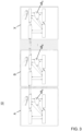
- the tracking system A pursuant to Fig. 1 forms part of a distributed tracking system 10 ( Fig. 3 ) for tracking of objects 14 to be transported by a plurality of transport vehicles 46.
- the distributed tracking system 10 comprises a plurality of tracking systems A, B, ..., X that are identically built or compatible to the embodiment of the tracking system A pursuant to Fig. 1 , so that each tracking system of the plurality of tracking systems A, B, ..., X comprises a cloud-based computer system 48 A , 48 B , , 48x.
- each tracking systems A, B, ..., X is depicted with their own cloud-based computer system 48 A , 48 B , , 48 X , it is in the sense of the invention that said tracking systems A, B, ..., X share the same cloud-based computer system.
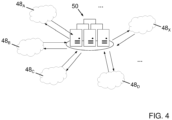
- Fig. 4 is a schematic illustration of a cloud-based computer environment of the distributed tracking system 10 pursuant to Fig. 3 .
- the cloud-based computer systems 48 A , 48 B , 48 C , 48 D , , 48 X of the plurality of tracking systems A, B, ..., X are interlinked by a central data center 50, with data access being regulated by granting authorizations.
- the cloud-based computer systems 48 A , 48 B , 48 C , 48 D , , 48 X of the plurality of tracking systems A, B, ..., X are thus configured for interchanging data related to digital visual identifier sets 28 and current positions of objects 14 to be transported by the plurality of transport vehicles 46.
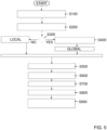
- one of the mobile computing devices 36 is activated in one step S100 for generating the digital visual identifier set 28 of the object 14 to be transported and tracked. It is understood that this step S100 is carried out for each of the objects 14 to be transported and tracked and for each newly added object 14 to be transported and tracked.
- step S200 the digital visual identifier set 28 is communicated to the cloud-based computer system 48 A by one of the mobile computing devices 36.
- step S300 the user can decide to deny or allow global sharing of the digital visual identifier set 28. If global sharing is denied, the tagging device 16 of the object set 12 is tracked only locally.
- the cloud-based computer system 48 A of the tracking system A shares the digital visual identifier set 28 with the central data center 50 in another step S400.
- the real-time location data GPS are then available in the central data center 50 for all remote parties with granted authorization.
- the tagging device 16 of the object set 12 can be tracked globally.
- step S500 the user activates one of the mobile computing devices 36 for tracking the tagging device 16.
- the digital visual identifier set 28 of the object set 12 to be transported is tracked for receiving real-time location data in a next step S600.
- the received real-time location data are communicated by the activated mobile computing device 36 to the cloud-based computer system 48 A in a further step S700.
- the data are shared with all remote parties with granted authorization for data access.
- the position of the tagging device 16 of the object set 12 to be transported is made available in the cloud-based computer system 48 A in another step S800.
- one of the mobile computing devices 36 of the tracking system A is activated for visualizing the object 14 or the objects 14 based on the received real-time location data, or a mobile computing device 36 of one of the other tracking systems B, ..., X of the distributed tracking system 10 is activated for visualizing the object 14 or the objects 14 based on data received from the cloud-based computer system 48 A or the central data center 50.
- a 3D representation of the object 14 or the objects 14 is visualized together with the camera video stream as background.
- the step 900 may include providing data for visualizing a position of the object 14 or the objects 14 by the augmented reality device 44, i.e. the smartglasses device.
- the telematics control unit 24 is configured for directly exchanging digital visual identifier sets 28 with the telematics control units 24 of compatible systems for tracking of objects 14 that are partially installed in other transport vehicles 46, as is schematically indicated in Fig. 3 .
- the proposed tracking system and method allow for tracking tagging devices globally when mobile devices, vehicles, and/or smart glasses are nearby.
- the tracking system also allows to visualize the objects which the tagging devices attached to them, without the presence of the object.
Landscapes
- Engineering & Computer Science (AREA)
- Computer Networks & Wireless Communication (AREA)
- Signal Processing (AREA)
- Traffic Control Systems (AREA)
Abstract
Description
- The invention relates to a tracking system for tracking of objects to be transported by at least one transport vehicle, and to a method of tracking objects to be transported by at least one transport vehicle, employing at least one such tracking system.
- In the prior art, various solutions of methods and systems for tracking of objects such as tools are known. As a typical example, tools may be used by professional craftsmen who are supposed to work for a customer or on a construction site to complete an order, and the tools and other auxiliary equipment may be located in a transport van. The known solutions may provide support in preventing loss of tools through forgetfulness, loss or unauthorized removal by alerting users.
- For instance, international application
WO 2017/197409 A1 proposes a solution for a personal safety and tool loss prevention system and method for persons working at a location remote from a home location. The system comprises a server, a portable tracking device and at least one tracking tag. The server has the ability to store information relating to a vehicle, to a person associated with that vehicle and to tools and equipment associated with that vehicle. The portable tracking device is adapted to be carried or worn by the person when leaving the vehicle. The at least one tracking tag is adapted to be mounted on a tool or equipment used by the person at locations remote from the vehicle. The portable tracking device includes a communication device adapted to connect the tracking device to the server and a receiving device adapted to receive signals from the or each tracking tag. The tracking tag includes a transmitting device adapted to communicate with the tracking device while the tracking tag is within a limited distance of that tracking device. The communication device is adapted to send a signal to the server indicative of whether or not the receiving device of that tracking device is in communication with the tracking tag. The server is adapted to provide an indication when it detects that the tracking tag is not in communication with the tracking device. - The system may include at least two tracking devices, one of which remains on a vehicle and the other is carried by a worker to job sites remote from the truck, multiple tracking tags, and a server, to which the tracking devices are connected via a telecom platform and a tracking application. The server may be a cloud-based server. Each tracking device has cellular, GPS, and Bluetooth components among others. The tracking tags include Bluetooth transmitters and can be attached to tools and equipment. The server communicates with all tracking devices, and manages a list of tracking tags attached to tools and equipment. The list of tracking tags may be edited to reflect the tools and equipment associated with a particular group of tracking devices.
- While tools are in the vehicle or storage facility, the first tracking device electronically tethers all tools to itself. When a worker removes a tool from the vehicle and takes it to a jobsite, the second tracking device (the one carried by the worker) electronically tethers that specific tool to itself, essentially handing-off the tool from the first tracking device to the second tracking device automatically and without input or action by any worker. All tracking devices communicate via cellular or other wireless means to the server.
- The system does not provide information as to the location of a specific tool, but rather reduces the risk of loss of tools and equipment by immediately and automatically alerting users that a tool has been forgotten, lost, or stolen, at a time when the tool is still close enough to retrieve easily.
- Further in
US 2018/322376 A1 is described an asset tag that is adapted to be mounted to an asset such as tools. The asset tag comprises a first component encoded with a first ID unique to the asset tag. The first component has a first wireless interface and is adapted to transmit first broadcast signals via the first wireless interface over a first range. The first broadcast signals include the first ID. The asset tag further includes a user-actuatable button and processing circuitry, which is coupled to the button and to at least the first wireless interface. The processing circuitry is configured for (i) determining whether a predetermined gesture has been performed by a user using the button and (ii) if the predetermined gesture has been performed, transmitting via the first wireless interface to a wireless access point a restock message, the restock message including the first ID and indicating that restocking is required of assets corresponding to the first ID. - A wireless portable device may be provided comprising a short-range (e.g. NFC) and/or long-range (e.g. Bluetooth) wireless transceiver, a display, an input device and the processing circuitry, coupled to the short-range and/or long-range wireless transceiver, display, and input device. The processing circuitry may be configured for (i) receiving one or more user inputs via the input device, the one or more user inputs identifying an asset, a tag ID being associated in a database with the asset; and (ii) transmitting a search message to a wireless access point, wherein the search message incorporates at least the tag ID.
- A proposed asset tracking system for use with the wireless portable device may comprise a wireless access point coupled in a network to a central control computer. The central control computer stores at least a copy of the database, and the database stores, for each tag ID associated therewith, a location ID for a location at which an asset corresponding to the tag ID is stored and/or is available. The wireless access point is configured to receive the search message and to incorporate a location ID of the wireless access point in the search message. The central control computer is configured for (i) receiving the search message, and (ii) querying the database to extract a location ID based on the tag ID.
- The short-range (e.g. NFC) wireless transceiver component of the composite tag allows the scanning of the composite tag to record data to a cloud based software. It further allows the booking of a particular asset/tool to a job. E.g. an engineer takes a drill and an angle grinder from several assets on their vehicle. These can be booked to the job, so it records them going on to a particular site. When the engineer gets back to the vehicle he can scan them back onto the vehicle or home store. This gives a record and audit trail of the time specific tools are allocated to a job.
- A cloud-based (asset monitoring/tracking) software allows a Bluetooth network of a whole community of community users to track specific assets/tools.
- The composite tag placed on an asset can be NFC scanned to tether the asset to a mobile device using Bluetooth short range wireless communication technology. The composite tags of a specific asset can be scanned by another engineer to show an asset/tool transfer from one engineer to another in the cloud-based (asset monitoring/tracking) software. This also automatically tethers the Bluetooth component of the composite tag to the new engineer's smart device. This allows the lending of tools between operatives to be a seamless process.
- Moreover,
US 9,462,357 B2 - The system comprises an asset tag affixed to each of the plurality of assets, wherein each asset tag comprises a unique identification beacon for the asset with which the asset tag is associated. The asset tag is configured to communicate through one or more transponder antennas to a transponder base having a central processor programmed for filtering data from the plurality of tags to accurately determine the presence or absence of a tag within a predetermined space, wherein the central processor is further programmed to identify tags by asset owner. The transponder base may be wirelessly connected to the Internet via cellular connection or satellite connection to a cloud based server. The transponder base may include GPS location means to track asset tags.
- The system further includes a data base for storing asset information for a plurality of assets. The database comprises a list of preselected suggested asset types for a plurality of predetermined task types and is in communication with the central processor. The asset information comprises at least information relating to location, ownership, maintenance and repair of the plurality of assets. The system further comprises tracking software associated with the central processor. The tracking software is configured to track a location of each of the plurality of assets. The software is further configured to compare the list of predetermined suggested asset types with the assets within the predetermined space and communicate any differences between the list and the asset to at least one human readable device. The central processor is in wireless communication with the at least one human readable device and is configured to electronically report information to the device. The information is selected from the group consisting of asset usage, asset location, asset movement, asset ownership, and asset presence within a job site.
- Users can be alerted by the proposed system and method about whether tagged assets (such as reclamation tools) have been left behind unintentionally. Tags that should be but are not in contact with transponders are visible to the user. Anyone with access to the system can find this out and, if necessary, take action. The system detects when tags from a finished job are left behind and sends a notification (text message, etc.) to desired parties. The system can provide users with information about where "lost" equipment is located.
- One drawback of solutions known in the prior art is that tagged objects can get lost easily when they are not in the coverage area of an active mobile device such as a smartphone or a tablet computer. Another issue is that the tagging devices are usually registered using a unique device ID, e.g. a MAC (media access control) address. They are generally named by the user only later, then indicating the name of the object they are attached to. The existing solutions do not allow to incorporate information about the tagged object into the tagging device. This also makes the tagged objects hard to locate as other active mobile devices can only see with the name or some navigation directions to a tagging device, especially when the tagged objects are lost but in the coverage area of the active mobile device.
- In view of the prior art, the field of tracking of tagged objects such as tools to be transported by at least one transport vehicle, still offers room for improvement.
- It is an object of the invention to provide a system and a method for tracking tagged objects, which are to be transported by at least one transport vehicle, with an as little as possible tracking failure rate. At the same time, it is a further object of the invention to provide a more intuitive way of representing the tracking of the tagged objects. The tagged objects can in particular be formed by tools for professional craftsmen who work at a customer's site or on a construction site and thus remote from a central workshop. In one aspect of the invention, the object is achieved by a tracking system with the features of claim 1. The object is further achieved by a distributed tracking system for tracking of objects to be transported by a plurality of transport vehicles with the features of claim 8. The object is furthermore achieved by a method according to claim 9 of tracking objects to be transported by at least one transport vehicle. Further, particularly advantageous embodiments of the invention are disclosed in the respective dependent claims.
- It should be noted that the features and measures listed individually in the following description can be combined with one another in any technically meaningful manner and show further embodiments of the invention. The description additionally characterizes and specifies the invention in particular in connection with the figures.
- In one aspect of the invention, a tracking system for tracking of objects to be transported by at least one transport vehicle is provided.
- The tracking system comprises at least one object set comprising an object and at least one tagging device attached to the object to be tracked. The tagging device includes a short-range wireless communication member that is configured for sending out a unique identification signal. The tracking system further includes a short-range wireless communication unit that is arrangeable in the transport vehicle and that is at least configured to receive the unique identification signals sent out by each short-range wireless communication member, and at least one mobile computing device, which includes at least an optical camera and a LIDAR sensor device.
- In the sense of the present invention, the phrase "being configured to", shall be understood as being specifically programmed, laid out, furnished or arranged. The unique identification signal of the at least one tagging device may represent, without being limited to, a MAC (media access control) address.
- It is proposed that the tracking system comprises an electronic main controller unit and a telematics control unit, which are arrangeable in the transport vehicle, wherein the electronic main controller unit is operatively coupled at least to the short-range wireless communication unit and the telematics control unit, and the telematics control unit is configured for communicating with a cloud-based computer system.
- Further, the at least one mobile computing device comprises short-range wireless communication means for receiving the unique identification signals, and wireless communication means for communicating with the cloud-based computer system.
- It is further proposed that the at least one mobile computing device is configured for
- for each object set, generating a digital visual identifier set at least comprising a scanned image of the at least one object to be transported and digital data representing the unique identification signal of the respective tagging device,
- communicating the digital visual identifier set to the cloud-based computer system,
- tracking the unique identification signal of the at least one object set to be transported for receiving real-time location data, and
- during tracking, communicating the received real-time location data to the cloud-based computer system.
- Examples for objects to be transported include, without being limited to, bags, parcels, wallets, personal items, and craftsmen tools in a general meaning, including tools with plug and cordless tools such as fastening tools, saws, hammer drills, chargeable screwdrivers, hammers, but also equipment items and other objects such as portable batteries.
- The mobile computing device may be formed by, without being limited to, a mobile phone, a tablet computer, a laptop computer or a wearable device. The short-range wireless communication member of the tagging device may be formed, without being limited to, by a Bluetooth® beacon or may be based on BLE (Bluetooth Low Energy) or WiFi radio standard. The BLE (Bluetooth Low Energy) radio standard has the advantage of being very energy-efficient.
- LIDAR (light detection and ranging) sensor devices as devices for measuring distances (ranging) by illuminating an object with laser light and measuring the reflection with a sensor are well known in the art, for instance in applications such as autonomous driving, and need not be described in more detail herein. Further, many mobile computing devices are already equipped with a LIDAR sensor device these days.
- Algorithms for detecting nearby Bluetooth devices based on determining respective signal strengths are available in the art and are described, for instance, in the article by Devanshi, Devanshi & Agrawal, Sunil & Singh, Sarvjit, (2014), "Indoor Localization based on Bluetooth Technology: A Brief Review", International Journal of Computer Applications, 97, 31-33, 10.5120/17029-7327, and in the article by A. N. Raghavan, H. Ananthapadmanaban, M. S. Sivamurugan and B. Ravindran, "Accurate mobile robot localization in indoor environments using bluetooth", 2010 IEEE International Conference on Robotics and Automation, Anchorage, AK, 2010, pp. 4391-4396, doi: 10.1109/ROBOT.2010.5509232.
- The tagging devices can have their own energy source such as a battery and might use the battery of the transport vehicle for charging. They may be charged, for instance, by employing USB ports. In other embodiments they may be also be charged inductively using a wireless power transfer technology.
- Preferably, the wireless communication means of the at least one mobile computing device for communicating with the cloud-based computer system is compatible to at least one mobile telecommunication standard out of GPRS (General Packet Radio Service), EDGE (Enhanced Data Rates for GSM Evolution), UMTS (Universal Mobile Telecommunications System), LTE(-Advanced) (Long-Term Evolution) and 5G.
- The proposed tracking system provides all the prerequisites for achieving, when using a suitable method for its operation, an improved, i.e. a lower tracking failure rate by making use of the various communication means that allow data access for many remote parties with granted authorization, even globally. Further, the proposed tracking system can provide input data for improved visualization for such parties. In appropriate embodiments, the proposed tracking system can provide visualization of objects without their presence, which eases finding lost objects.
- The proposed tracking system is primarily designed for land transport vehicles. However, it is also conceived within the scope of the present invention to employ the tracking system in commercial transport shipping vessels for tracking items such as containers, or in a cargo aircraft transporting various kinds of loads.
- In the sense of the present invention the term "object" is meant to have a general meaning, and shall include items such as tools with plug and cordless tools such as fastening tools, saws, hammer drills, chargeable screwdrivers, hammers, but also equipment items and other objects such as portable batteries. Further it should be noted, that although in particular tools used by professional craftsmen who are supposed to work at a customer or on a construction site are described in the above and the following, it is to be understood, that the invention could also be used for the parcel delivery sector or in passenger transport vehicle sector for item tracking like the sports bag or the jacket of a user, without being limited to these examples.
- In preferred embodiments of the tracking system, the at least one mobile computing device is further configured for visualizing the object or the objects based on data received from the cloud-based computer system. In this way, the at least one mobile computing device can provide augmented reality features to a user for providing a more intuitive way of representing the tracking of the tagged objects.
- For example, a 3D representation of a lost object can be visualized on the screen of the mobile computing device together with the camera video stream as background, wherein the 3D visual representation of the lost object is positioned on the location of the tagging device. This is a more intuitive, and more illustrative approach in comparison to conventional tracking employing, for instance, navigation instructions to a tagging device based on Bluetooth signals.
- Preferably, the tracking system includes an augmented reality device that is operatively coupleable to the at least one mobile computing device for directly receiving data for visualizing a position of the at least one object. In this way, the intuitive illustration of the tracking of the tagged objects can be improved even more in order to make it easier to find them.
- Preferably, the digital visual identifier set of at least one object set further comprises at least one out of a mesh representation and a texture mapping of the object to be transported. Adding these features to the digital data representing the unique identification signal of the respective tagging device can help to overcome issues that arise for instance when trying to locate an object that is lost but within a coverage area of the mobile computing device.
- Preferably, the at least one mobile computing device is configured to generate the mesh representation and/or perform the texture mapping of the object, for fast signal processing and prevention of faults.
- In preferred embodiments of the tracking system, the at least one mobile computing device further comprises short-range communication means and the electronic main controller unit further comprises compatible short-range communication means for direct wireless communication between the at least one mobile computing device and the electronic main controller unit. In this way the at least one mobile computing device can advantageously serve as an intermediate station between the electronic main controller unit of the transport vehicle and the cloud-based computer system. The mobile computing device or the mobile computing devices can connect directly to the electronic main controller unit of the transport vehicle in times when a connection to the cloud-based computer system cannot be established. Also, the electronic main controller unit of the transport vehicle can connect to the mobile device or the mobile devices when a connection to the cloud-based computer system cannot be established.
- In some embodiments of the tracking system, the short-range wireless communication means of the at least one mobile computing device that are configured at least for receiving the unique identification signals may be identical to the short-range communication means configured for direct wireless communication between the at least one mobile computing device and the electronic main controller unit. In other embodiments, the short-range wireless communication means for receiving the unique identification signals and the short-range communication means for direct wireless communication with the electronic main controller unit may be distinct units integrated in the at least one mobile computing device.
- In preferred embodiments of the tracking system, the telematics control unit is further configured for directly exchanging digital visual identifier sets with the telematics control unit of at least one compatible system for tracking of objects that is partially installed in another transport vehicle. In this way, mutually compatible tracking systems being partially installed in distinct transport vehicles can also communicate directly, besides using a communication path via the cloud-based computer system. This feature enables for tracking all tagging devices nearby a transport vehicle. Considering the potential large number of transport vehicles, especially in cities, a large coverage area can be achieved so that any tagging device can hardly ever be lost together with the object to which it is attached.
- Preferably, the at least one tagging device includes an electric energy storage unit, a digital processing unit, a digital data memory unit and a satellite-based radionavigation unit. By that, the real-time location data received by the at least one mobile computing device can be communicated during tracking to the cloud-based computer system in an especially easy manner. The satellite-based radionavigation unit can be formed, for example, by a Global Positioning System (GPS) unit, which is widely spread.
- In another aspect of the present invention, a distributed tracking system for tracking of objects to be transported by a plurality of transport vehicles is provided. In the sense of the present invention, the term "plurality" shall in particular be understood as a quantity of at least two. The distributed tracking system includes a plurality of tracking systems in accordance with the present invention. Each tracking system comprises a cloud-based computer system. The cloud-based computer systems of the tracking systems are configured for interchanging data related to digital visual identifier sets and current positions of objects to be transported by the plurality of transport vehicles.
- The benefits described beforehand in context with the tracking system in accordance with the present invention apply to the proposed distributed tracking system to the full extent. Moreover, the distributed tracking system has the advantage that all tagging devices that are nearby one of the transport vehicle can be tracked by all others users of one of the transport vehicles, either via communication between the cloud-based computer systems or via communication between the electronic main controller unit of their respective tracking systems.
- In yet another aspect of the present invention, a method of tracking objects to be transported by at least one transport vehicle, employing at least one tracking system or a distributed tracking system in accordance with the present invention, is provided.
- The method comprises at least the following steps of
- activating the at least one mobile computing device for generating, for each object set, a digital visual identifier set at least comprising a scanned image of the at least one object to be transported and digital data representing the unique identification signal of the respective tagging device,
- communicating the digital visual identifier set at least to the cloud-based computer system,
- tracking the unique identification signal of the at least one object to be transported for receiving real-time location data, and
- during tracking, communicating the received real-time location data to the cloud-based computer system.
- By employing the proposed method, an improved, i.e. a lower, tracking failure rate can be achieved by making use of the various communication means that allow data access for many remote parties with granted authorization, even globally. Further, the proposed method can provide improved visualization of tagged objects for such parties. In appropriate embodiments, the proposed method can provide visualization of objects without their presence, which eases finding lost objects.
- In preferred embodiments, the method further comprises the step of directly exchanging digital visual identifier sets between telematics control units of at least two compatible tracking systems for tracking of objects, wherein the at least two telematics control units are installed in distinct transport vehicles. By that, all tagging devices that are nearby one of the transport vehicle can be tracked by all others users of one of the transport vehicles, either via communication between the cloud-based computer systems or via communication between the telematics control unit of their respective tracking systems.
- Preferably, the method further comprises the step of activating the at least one mobile computing device for visualizing the object or the objects based on data received from the cloud-based computer system. By that, the at least one mobile computing device can provide augmented reality features to a user for providing a more intuitive way of representing the tracking of the tagged objects, and a more intuitive, and more illustrative approach of visualization in comparison to conventional methods can be accomplished.
- In preferred embodiments, the method further comprises the step of providing data for visualizing a position of the at least one object by an augmented reality device. By that, the intuitive illustration of the tracking of the tagged objects can be improved even more in order to make it easier to find them.
- These and other aspects of the invention will be apparent from and elucidated with reference to the embodiment or the embodiments and attached drawings described hereinafter, wherein:
- Fig. 1
- schematically shows a tracking system in accordance with the invention for tracking of objects to be transported by at least one transport vehicle,
- Fig. 2
- shows an outline of data flow within the tracking system pursuant to
Fig. 1 , - Fig. 3
- schematically shows a distributed tracking system in accordance with the invention for tracking of objects to be transported by a plurality of transport vehicles,
- Fig. 4
- is a schematic illustration of a cloud-based computer environment of the distributed tracking system pursuant to
Fig. 3 , and - Fig. 5
- is a flow chart of a method of tracking objects to be transported by at least one transport vehicle, employing the tracking system pursuant to
Fig. 1 . - In the different figures, parts that are the same are always denoted by the same reference numeral, for which reason they are usually described only once.
-
Fig. 1 schematically shows a tracking system A in accordance with the invention for tracking of objects that are to be transported by atransport vehicle 46, which in this specific embodiment is designed as a van for use by professional craftsmen. - The tracking system A includes a plurality of object sets 12, one of which is exemplarily shown in
Fig. 1 . Each object set 12 comprises anobject 14 and atagging device 16 that is attached to theobject 14 to be tracked. In this specific embodiment theobjects 14 can be formed by craftsmen tools and equipment items. - Each tagging
device 16 includes a short-rangewireless communication member 18 that is configured for sending out aunique identification signal 32 to potential surrounding receivers. In this specific embodiment, the short-rangewireless communication member 18 may be formed by an adapted Bluetooth beacon, and the unique identification signal 32 (Fig. 2 ) may be formed by a MAC address. The short-range wireless communication members 18 (Fig. 1 ) include an electric energy storage unit, e.g. a battery, a digital processing unit, a digital data memory unit and a satellite-based radionavigation unit (all not shown), which in this specific embodiment may be designed as a GPS unit. The short-rangewireless communication members 18 are always in operation until the respective electric energy storage unit runs out of power. - The tracking system A further comprises a short-range
wireless communication unit 26 that is arranged in thetransport vehicle 46 and that is configured to receive the unique identification signals 32 sent out by the short-rangewireless communication member 18 of each taggingdevice 16. - The tracking system A also includes an electronic
main controller unit 20 and atelematics control unit 24, both of which are arranged in thetransport vehicle 46. The electronicmain controller unit 20 is operatively coupled to the short-rangewireless communication unit 26 and thetelematics control unit 24, and thetelematics control unit 24 is configured for communicating with a cloud-based computer system 48A, which also forms part of the tracking system A. The cloud-based computer system 48A is a high-performance computing center offering high computational power and storage capacity, serving both as a storage and processing unit. - Moreover, the tracking system A includes
mobile computing devices 36 that in this specific embodiment are designed as a smart phone and a tablet computer. InFig. 1 , only onemobile computing device 36 is exemplarily shown. Themobile computing devices 36 each include an optical camera, a LIDAR sensor device and short-range wireless communication means 38, which may be compatible to the Bluetooth beacon communication standard, for receiving the unique identification signals 32. Themobile computing devices 36 each also comprise wireless communication means 40 for communicating with the cloud-based computer system 48A. In this specific embodiment, the wireless communication means 40 for communicating with the cloud-based computer system 48A may be compatible to the LTE (4G) mobile telecommunication standard. - The
mobile computing devices 36 further comprise additional components such as a central processing unit (CPU), a graphics processing unit (GPU), an optional artificial intelligence (Al) processing unit, a random access memory (RAM) unit, a digital data memory unit and an electric power unit (all not shown). - Each one of the
mobile computing devices 36 further comprises short-range communication means 42, and the electronicmain controller unit 20 further comprises compatible short-range communication means 22, for the purpose of direct wireless communication between each one of themobile computing devices 36 and the electronicmain control unit 20. - In addition, the tracking system A is equipped with an
augmented reality device 44 that is operatively coupled to themobile computing devices 36 for directly receiving data for visualizing a position of a selectedobject 14. In this specific embodiment, theaugmented reality device 44 may be formed by a smartglasses device. - In preparation of tracking a specific object set 12, one of the
mobile computing devices 36 is employed by a user to scan an image or images, by using the optical camera and the LIDAR sensor, of the object set 12 to be tracked. - Each one of the
mobile computing devices 36 is configured for generating a digital visual identifier set 28 (Fig. 2 ). The digital visual identifier set 28 comprises the scannedimage 30 of theobject 14 to be transported and tracked, digital data representing theunique identification signal 32 of thetagging device 16 of the respective object set 12, and a mesh representation and atexture mapping 34 of theobject 14 to be transported and tracked. - The tracking system A pursuant to
Fig. 1 forms part of a distributed tracking system 10 (Fig. 3 ) for tracking ofobjects 14 to be transported by a plurality oftransport vehicles 46. The distributedtracking system 10 comprises a plurality of tracking systems A, B, ..., X that are identically built or compatible to the embodiment of the tracking system A pursuant toFig. 1 , so that each tracking system of the plurality of tracking systems A, B, ..., X comprises a cloud-basedcomputer system 48A, 48B, , 48x. Although each tracking systems A, B, ..., X is depicted with their own cloud-based computer system 48A, 48B, , 48X, it is in the sense of the invention that said tracking systems A, B, ..., X share the same cloud-based computer system. -
Fig. 4 is a schematic illustration of a cloud-based computer environment of the distributedtracking system 10 pursuant toFig. 3 . The cloud-based computer systems 48A, 48B, 48C, 48D, , 48X of the plurality of tracking systems A, B, ..., X are interlinked by acentral data center 50, with data access being regulated by granting authorizations. The cloud-based computer systems 48A, 48B, 48C, 48D, , 48X of the plurality of tracking systems A, B, ..., X are thus configured for interchanging data related to digital visual identifier sets 28 and current positions ofobjects 14 to be transported by the plurality oftransport vehicles 46. - In the following, a possible embodiment of a method of tracking
objects 14 to be transported by thetransport vehicle 46, employing the tracking system A pursuant toFig. 1 , will be described with reference toFig. 1, to Fig. 2 , which shows an outline of data flow within the tracking system A pursuant toFig. 1 , and toFig. 5 , by which a flowchart of the method is provided. In preparation of executing the method steps it is understood that all involved units and devices are in an operational state. - After the start of the method, one of the
mobile computing devices 36 is activated in one step S100 for generating the digital visual identifier set 28 of theobject 14 to be transported and tracked. It is understood that this step S100 is carried out for each of theobjects 14 to be transported and tracked and for each newly addedobject 14 to be transported and tracked. - In a further step S200 the digital visual identifier set 28 is communicated to the cloud-based computer system 48A by one of the
mobile computing devices 36. At a prompt step S300, the user can decide to deny or allow global sharing of the digital visual identifier set 28. If global sharing is denied, the taggingdevice 16 of the object set 12 is tracked only locally. - If global sharing is allowed, the cloud-based computer system 48A of the tracking system A shares the digital visual identifier set 28 with the
central data center 50 in another step S400. The real-time location data GPS are then available in thecentral data center 50 for all remote parties with granted authorization. The taggingdevice 16 of the object set 12 can be tracked globally. - In another step S500, the user activates one of the
mobile computing devices 36 for tracking thetagging device 16. In the following, the digital visual identifier set 28 of the object set 12 to be transported is tracked for receiving real-time location data in a next step S600. - During tracking, the received real-time location data are communicated by the activated
mobile computing device 36 to the cloud-based computer system 48A in a further step S700. By that, the data are shared with all remote parties with granted authorization for data access. - The position of the
tagging device 16 of the object set 12 to be transported is made available in the cloud-based computer system 48A in another step S800. - In another step 900, one of the
mobile computing devices 36 of the tracking system A is activated for visualizing theobject 14 or theobjects 14 based on the received real-time location data, or amobile computing device 36 of one of the other tracking systems B, ..., X of the distributedtracking system 10 is activated for visualizing theobject 14 or theobjects 14 based on data received from the cloud-based computer system 48A or thecentral data center 50. On the screen of the respective activatedmobile computing device 36, a 3D representation of theobject 14 or theobjects 14 is visualized together with the camera video stream as background. - Alternatively or in addition, the step 900 may include providing data for visualizing a position of the
object 14 or theobjects 14 by theaugmented reality device 44, i.e. the smartglasses device. - It is noted that another option exists for sharing the real-time location data of the
tagging devices 16 in or nearby thetransport vehicle 46 in case that another one of the tracking systems B, ..., X of the distributedtracking system 10 is close enough to let the ranges of thetelematics control units 24 of the two tracking systems overlap (Fig. 3 ). - The
telematics control unit 24 is configured for directly exchanging digital visual identifier sets 28 with thetelematics control units 24 of compatible systems for tracking ofobjects 14 that are partially installed inother transport vehicles 46, as is schematically indicated inFig. 3 . - The proposed tracking system and method allow for tracking tagging devices globally when mobile devices, vehicles, and/or smart glasses are nearby. The tracking system also allows to visualize the objects which the tagging devices attached to them, without the presence of the object.
- While the invention has been illustrated and described in detail in the drawings and foregoing description, such illustration and description are to be considered illustrative or exemplary and not restrictive. The invention is not limited to the disclosed embodiments.
-
- 10
- distributed tracking system
- 12
- object set
- 14
- object
- 16
- tagging device
- 18
- short-range wireless communication member
- 20
- electronic main controller unit
- 22
- short-range communication means
- 24
- telematics control unit
- 26
- short-range wireless communication unit
- 28
- digital visual identifier set
- 30
- scanned image of the object
- 32
- unique identification signal
- 34
- mesh representation and texture mapping
- 36
- mobile computing device
- 38
- short-range wireless communication means
- 40
- wireless communication means
- 42
- short-range communication means
- 44
- augmented reality device
- 46
- transport vehicle
- 48
- cloud-based computer system
- 50
- central data center
- A
- tracking system
- B
- tracking system
- X
- tracking system
- GPS
- real-time location data
- S100
- activate mobile computing device for generating digital visual identifier set
- S200
- communicate digital visual identifier set to cloud-based computer system
- S300
- prompt for denying or allowing global sharing
- S400
- sharing digital visual identifier set with central data center
- S500
- activate mobile computing device for tracking tagging device
- S600
- receiving real-time location data
- S700
- communicate real-time location data to cloud-based computer system
- S800
- making position of the tagging device available in cloud-based computer system
- S900
- activating mobile computing device for visualizing object
Claims (12)
- A tracking system (A) for tracking of objects to be transported by at least one transport vehicle (46), the tracking system (A) including- at least one object set (12) comprising an object (14) and at least one tagging device (16) attached to the object (14) to be tracked, the tagging device (16) including a short-range wireless communication member (18) that is configured for sending out a unique identification signal (32),- a short-range wireless communication unit (26) that is arrangeable in the transport vehicle (46) and that is at least configured to receive the unique identification signals (32) sent out by each short-range wireless communication member (18), and- at least one mobile computing device (36) at least including an optical camera and a LIDAR sensor device,characterized byan electronic main controller unit (20) and a telematics control unit (24), which are arrangeable in the transport vehicle (46), wherein the electronic main controller unit (20) is operatively coupled at least to the short-range wireless communication unit (26) and the telematics control unit (24), and the telematics control unit (24) is configured for communicating with a cloud-based computer system (48A), whereinthe at least one mobile computing device (36) comprises short-range wireless communication means (38) for receiving the unique identification signals (32), and wireless communication means (40) for communicating with the cloud-based computer system (48A), and whereinthe at least one mobile computing device (36) is configured for- for each object set (12), generating a digital visual identifier set (28) at least comprising a scanned image of the at least one object (14) to be transported and digital data representing the unique identification signal (32) of the respective tagging device (16),- communicating the digital visual identifier set (28) to the cloud-based computer system (48A),- tracking the unique identification signal (32) of the at least one object set (12) to be transported for receiving real-time location data, and- during tracking, communicating the received real-time location data to the cloud-based computer system (48A).
- The tracking system (A) as claimed in claim 1,
characterized in that
the at least one mobile computing device (36) is further configured for visualizing the object (14) or the objects (14) based on data received from the cloud-based computer system (48A). - The tracking system (A) as claimed in claims 1 or 2,
characterized by
an augmented reality device (36) that is operatively coupleable to the at least one mobile computing device (36) for directly receiving data for visualizing a position of the at least one object (14). - The tracking system (A) as claimed in any one of the preceding claims, characterized in that
the digital visual identifier set (28) of at least one object set (12) further comprises at least one out of a mesh representation and a texture mapping (34) of the object (14) to be transported. - The tracking system (A) as claimed in any one of the preceding claims, characterized in that
the at least one mobile computing device (36) further comprises short-range communication means (42) and the electronic main controller unit (20) further comprises compatible short-range communication means (22) for direct wireless communication between the at least one mobile computing device (36) and the electronic main controller unit (20). - The tracking system (A) as claimed in any one of the preceding claims, characterized in that
the telematics control unit (24) is further configured for directly exchanging digital visual identifier sets (28) with the telematics control unit (24) of at least one compatible system (B,..., X) for tracking of objects (14) that is partially installed in another transport vehicle (46). - The tracking system (A) as claimed in any one of the preceding claims, characterized in that
the at least one tagging device (16) includes an electric energy storage unit, a digital processing unit, a digital data memory unit and a satellite-based radionavigation unit. - A distributed tracking system (10) for tracking of objects (14) to be transported by a plurality of transport vehicles (46), comprising a plurality of tracking systems (A, B, ..., X) as claimed in any one of claims 1 to 7, wherein each tracking system (A, B, ..., X) comprises a cloud-based computer system (48A, 48B, 48c, 48D, ..., 48x),
characterized in that
the cloud-based computer systems (48A, 48B, 48C, 48D, ..., 48x) of the tracking systems (A, B, ..., X) are configured for interchanging data related to digital visual identifier sets (28) and current positions of objects (14) to be transported by the plurality of transport vehicles (46). - Method of tracking objects (14) to be transported by at least one transport vehicle (46), employing at least one tracking system (A) as claimed in any one of claims 1 to 7 or a distributed tracking system (10) as claimed in claim 8, the method comprising at least the following steps of- activating (S100) the at least one mobile computing device (36) for generating, for each object set (12), a digital visual identifier set (28) at least comprising a scanned image of the at least one object (14) to be transported and digital data representing the unique identification signal (32) of the respective tagging device (16),- communicating (S200) the digital visual identifier set (28) at least to the cloud-based computer system (48A),- tracking (S500) the unique identification signal (32) of the at least one object (14) to be transported for receiving real-time location data, and- during tracking, communicating (S700) the received real-time location data to the cloud-based computer system (48A).
- The method as claimed in claim 9, further comprising the step of directly exchanging digital visual identifier sets (28) between telematics control units (24) of at least two compatible tracking systems (A, B, ..., X) for tracking of objects (14), wherein the at least two telematics control units (24) are installed in distinct transport vehicles (46).
- The method as claimed in claims 9 or 10, further comprising the step of activating (S900) the at least one mobile computing device (36) for visualizing the object (14) or the objects (14) based on data received from the cloud-based computer system (48A).
- The method as claimed in any one of claims 9 to 11, further comprising the step of providing data for visualizing a position of the at least one object (14) by an augmented reality device.
Priority Applications (3)
| Application Number | Priority Date | Filing Date | Title |
|---|---|---|---|
| EP22151019.1A EP4210358B1 (en) | 2022-01-11 | 2022-01-11 | A connected system for tracking of tagged objects |
| CN202310012766.0A CN116437295A (en) | 2022-01-11 | 2023-01-05 | Connected system for tracking tagged objects |
| US18/095,259 US12659692B2 (en) | 2022-01-11 | 2023-01-10 | Connected system for tracking of tagged objects |
Applications Claiming Priority (1)
| Application Number | Priority Date | Filing Date | Title |
|---|---|---|---|
| EP22151019.1A EP4210358B1 (en) | 2022-01-11 | 2022-01-11 | A connected system for tracking of tagged objects |
Publications (2)
| Publication Number | Publication Date |
|---|---|
| EP4210358A1 true EP4210358A1 (en) | 2023-07-12 |
| EP4210358B1 EP4210358B1 (en) | 2024-12-25 |
Family
ID=80121780
Family Applications (1)
| Application Number | Title | Priority Date | Filing Date |
|---|---|---|---|
| EP22151019.1A Active EP4210358B1 (en) | 2022-01-11 | 2022-01-11 | A connected system for tracking of tagged objects |
Country Status (3)
| Country | Link |
|---|---|
| US (1) | US12659692B2 (en) |
| EP (1) | EP4210358B1 (en) |
| CN (1) | CN116437295A (en) |
Citations (6)
| Publication number | Priority date | Publication date | Assignee | Title |
|---|---|---|---|---|
| US20140357295A1 (en) * | 2013-06-03 | 2014-12-04 | The Morey Corporation | Geospatial asset tracking systems, methods and apparatus for acquiring, manipulating and presenting telematic metadata |
| US9462357B2 (en) | 2013-09-11 | 2016-10-04 | Michael Westick | Automated asset tracking system and method |
| WO2017197409A1 (en) | 2016-05-13 | 2017-11-16 | Nana Technologies, Llc | Personal safety and tool loss prevention system |
| US20180007504A1 (en) * | 2016-07-01 | 2018-01-04 | Laird Technologies, Inc. | Telematics devices and systems |
| US20180322376A1 (en) | 2017-05-02 | 2018-11-08 | Inventor-E Limited | Asset tag and methods and devices for restocking and asset tracking |
| US20190391634A1 (en) * | 2018-06-22 | 2019-12-26 | Blackberry Limited | Method and System for Asset Tracking |
Family Cites Families (21)
| Publication number | Priority date | Publication date | Assignee | Title |
|---|---|---|---|---|
| EP1783570A1 (en) | 2005-11-03 | 2007-05-09 | Snap-on Incorporated | Tool monitoring system |
| CA2560800C (en) | 2006-01-20 | 2014-08-26 | Geo 3D Inc. | Automated asset detection, location measurement and recognition |
| US8842183B2 (en) | 2008-08-08 | 2014-09-23 | Snap-On Incorporated | Image-based inventory control system with automatic calibration and image correction |
| US8538838B2 (en) * | 2008-10-07 | 2013-09-17 | Qualcomm Incorporated | System for pairing vehicle components |
| WO2011038018A1 (en) | 2009-09-23 | 2011-03-31 | Earthsearch Communications International, Inc. | Device and process for monitoring secure storage and delivery of items |
| WO2013188580A2 (en) | 2012-06-12 | 2013-12-19 | Snap-On Incorporated | Enabling communication between an inventory control system and a remote system over a network |
| US8970377B2 (en) | 2012-09-06 | 2015-03-03 | Robert Bosch Gmbh | System and method for tracking items stored in a compartment |
| EP2916189B1 (en) | 2014-03-06 | 2019-05-08 | Hexagon Technology Center GmbH | Quality assured manufacturing |
| US20170053234A1 (en) * | 2015-08-21 | 2017-02-23 | Trakkx Com Llc | Method and systems for tracking assets of shipping transactions in real time |
| EP3448726B1 (en) * | 2015-11-18 | 2023-10-11 | Discovery Limited | A tracking and theft-recovery system for mobile assets |
| US10179597B2 (en) | 2016-06-27 | 2019-01-15 | Jack Wade | Automated wayside asset monitoring with optical imaging and visualization |
| CN113543030B (en) * | 2016-09-12 | 2024-11-19 | 工业科技有限公司 | System and method for beacon broadcasting with relevant range |
| DE102017205306A1 (en) | 2017-03-29 | 2018-10-04 | Robert Bosch Gmbh | Storage system |
| US10075811B1 (en) * | 2017-08-16 | 2018-09-11 | Tile, Inc. | Tracking device operation in risk-classified zone |
| CN110651488B (en) | 2019-01-23 | 2021-04-27 | 灵动科技(北京)有限公司 | Autonomous broadcast systems for self-propelled vehicles |
| GB2586198A (en) | 2019-03-08 | 2021-02-17 | Tescap Ltd | A monitoring and recording system |
| GB2583102A (en) | 2019-04-16 | 2020-10-21 | Ford Global Tech Llc | Vehicle-distributed asset management |
| KR102739588B1 (en) * | 2019-09-05 | 2024-12-06 | 삼성전자주식회사 | Electronic Device For Supporting Wireless Mobile Communication For Vehicle and Method For Operating The same |
| EP4073739A4 (en) * | 2019-12-10 | 2023-01-04 | Woodside Energy Technologies Pty Ltd | An asset management system |
| US11535196B2 (en) * | 2020-11-05 | 2022-12-27 | Ford Global Technologies, Llc | Remote vehicle motive control with optimized mobile device localization |
| US12222209B2 (en) * | 2021-02-26 | 2025-02-11 | Here Global B.V. | Method, apparatus, and system for shipment tracking |
-
2022
- 2022-01-11 EP EP22151019.1A patent/EP4210358B1/en active Active
-
2023
- 2023-01-05 CN CN202310012766.0A patent/CN116437295A/en active Pending
- 2023-01-10 US US18/095,259 patent/US12659692B2/en active Active
Patent Citations (6)
| Publication number | Priority date | Publication date | Assignee | Title |
|---|---|---|---|---|
| US20140357295A1 (en) * | 2013-06-03 | 2014-12-04 | The Morey Corporation | Geospatial asset tracking systems, methods and apparatus for acquiring, manipulating and presenting telematic metadata |
| US9462357B2 (en) | 2013-09-11 | 2016-10-04 | Michael Westick | Automated asset tracking system and method |
| WO2017197409A1 (en) | 2016-05-13 | 2017-11-16 | Nana Technologies, Llc | Personal safety and tool loss prevention system |
| US20180007504A1 (en) * | 2016-07-01 | 2018-01-04 | Laird Technologies, Inc. | Telematics devices and systems |
| US20180322376A1 (en) | 2017-05-02 | 2018-11-08 | Inventor-E Limited | Asset tag and methods and devices for restocking and asset tracking |
| US20190391634A1 (en) * | 2018-06-22 | 2019-12-26 | Blackberry Limited | Method and System for Asset Tracking |
Non-Patent Citations (2)
| Title |
|---|
| A. N. RAGHAVANH. ANANTHAPADMANABANM. S. SIVAMURUGANB. RAVINDRAN: "Accurate mobile robot localization in indoor environments using bluetooth", 2010 IEEE INTERNATIONAL CONFERENCE ON ROBOTICS AND AUTOMATION, ANCHORAGE, AK, 2010, pages 4391 - 4396 |
| DEVANSHI, DEVANSHIAGRAWAL, SUNILSINGH, SARVJIT: "Indoor Localization based on Bluetooth Technology: A Brief RevieW", INTERNATIONAL JOURNAL OF COMPUTER APPLICATIONS, vol. 97, 2014, pages 31 - 33 |
Also Published As
| Publication number | Publication date |
|---|---|
| CN116437295A (en) | 2023-07-14 |
| US20230224675A1 (en) | 2023-07-13 |
| EP4210358B1 (en) | 2024-12-25 |
| US12659692B2 (en) | 2026-06-16 |
Similar Documents
| Publication | Publication Date | Title |
|---|---|---|
| EP4017034B1 (en) | 5g positioning slam tags | |
| US10290211B2 (en) | Electronic fence (E-Fence) control technology for dockless sharing vehicles | |
| EP2948907B1 (en) | Kinematic asset management | |
| CN106664507B (en) | Enabled node delivery of notifications using elements of the wireless node network | |
| ES2676758B1 (en) | System | |
| US9462357B2 (en) | Automated asset tracking system and method | |
| CN101517432A (en) | Apparatus and method for locating individuals and objects using a tracking device | |
| WO2017109845A1 (en) | Vehicle logistics management system | |
| US20090309731A1 (en) | Method and system for tracking objects using Global Positioning System (GPS) receiver built in the Active Radio Frequency ID (RFID) receiver | |
| US12315235B2 (en) | Tracking system and method employing an artificial neural network for tracking tools in and nearby a transportation vehicle | |
| US20100250309A1 (en) | Asset management system and method for an automotive vehicle | |
| US20260101153A1 (en) | Power tool geofence tracking and dashboard | |
| KR20200043160A (en) | Manless notebook computer rental method | |
| EP4210358B1 (en) | A connected system for tracking of tagged objects | |
| JP6285599B1 (en) | Method and system for managing rental objects | |
| GB2583102A (en) | Vehicle-distributed asset management | |
| JP6537588B1 (en) | Search system and method | |
| CN106781604A (en) | Parking lot management system and method based on wireless positioning base station | |
| JP2019008770A (en) | Rental object management method | |
| US11070947B2 (en) | Distributed wireless network assisted object location | |
| JP6971050B2 (en) | Location management methods, location management systems, location management programs and mobile communication devices | |
| JP2002523785A (en) | Data carrier locating system and method | |
| JP6366804B1 (en) | Rental target management method | |
| JP6366805B1 (en) | Property management method | |
| JP2018091671A (en) | Search system, parking lot managing system, and search method |
Legal Events
| Date | Code | Title | Description |
|---|---|---|---|
| PUAI | Public reference made under article 153(3) epc to a published international application that has entered the european phase |
Free format text: ORIGINAL CODE: 0009012 |
|
| STAA | Information on the status of an ep patent application or granted ep patent |
Free format text: STATUS: THE APPLICATION HAS BEEN PUBLISHED |
|
| AK | Designated contracting states |
Kind code of ref document: A1 Designated state(s): AL AT BE BG CH CY CZ DE DK EE ES FI FR GB GR HR HU IE IS IT LI LT LU LV MC MK MT NL NO PL PT RO RS SE SI SK SM TR |
|
| STAA | Information on the status of an ep patent application or granted ep patent |
Free format text: STATUS: REQUEST FOR EXAMINATION WAS MADE |
|
| 17P | Request for examination filed |
Effective date: 20240112 |
|
| RBV | Designated contracting states (corrected) |
Designated state(s): AL AT BE BG CH CY CZ DE DK EE ES FI FR GB GR HR HU IE IS IT LI LT LU LV MC MK MT NL NO PL PT RO RS SE SI SK SM TR |
|
| STAA | Information on the status of an ep patent application or granted ep patent |
Free format text: STATUS: EXAMINATION IS IN PROGRESS |
|
| 17Q | First examination report despatched |
Effective date: 20240304 |
|
| GRAP | Despatch of communication of intention to grant a patent |
Free format text: ORIGINAL CODE: EPIDOSNIGR1 |
|
| STAA | Information on the status of an ep patent application or granted ep patent |
Free format text: STATUS: GRANT OF PATENT IS INTENDED |
|
| INTG | Intention to grant announced |
Effective date: 20241008 |
|
| GRAS | Grant fee paid |
Free format text: ORIGINAL CODE: EPIDOSNIGR3 |
|
| GRAA | (expected) grant |
Free format text: ORIGINAL CODE: 0009210 |
|
| STAA | Information on the status of an ep patent application or granted ep patent |
Free format text: STATUS: THE PATENT HAS BEEN GRANTED |
|
| AK | Designated contracting states |
Kind code of ref document: B1 Designated state(s): AL AT BE BG CH CY CZ DE DK EE ES FI FR GB GR HR HU IE IS IT LI LT LU LV MC MK MT NL NO PL PT RO RS SE SI SK SM TR |
|
| REG | Reference to a national code |
Ref country code: GB Ref legal event code: FG4D |
|
| REG | Reference to a national code |
Ref country code: CH Ref legal event code: EP |
|
| REG | Reference to a national code |
Ref country code: DE Ref legal event code: R096 Ref document number: 602022008935 Country of ref document: DE |
|
| REG | Reference to a national code |
Ref country code: IE Ref legal event code: FG4D |
|
| REG | Reference to a national code |
Ref country code: LT Ref legal event code: MG9D |
|
| PG25 | Lapsed in a contracting state [announced via postgrant information from national office to epo] |
Ref country code: HR Free format text: LAPSE BECAUSE OF FAILURE TO SUBMIT A TRANSLATION OF THE DESCRIPTION OR TO PAY THE FEE WITHIN THE PRESCRIBED TIME-LIMIT Effective date: 20241225 |
|
| PG25 | Lapsed in a contracting state [announced via postgrant information from national office to epo] |
Ref country code: FI Free format text: LAPSE BECAUSE OF FAILURE TO SUBMIT A TRANSLATION OF THE DESCRIPTION OR TO PAY THE FEE WITHIN THE PRESCRIBED TIME-LIMIT Effective date: 20241225 |
|
| PG25 | Lapsed in a contracting state [announced via postgrant information from national office to epo] |
Ref country code: BG Free format text: LAPSE BECAUSE OF FAILURE TO SUBMIT A TRANSLATION OF THE DESCRIPTION OR TO PAY THE FEE WITHIN THE PRESCRIBED TIME-LIMIT Effective date: 20241225 |
|
| PG25 | Lapsed in a contracting state [announced via postgrant information from national office to epo] |
Ref country code: NO Free format text: LAPSE BECAUSE OF FAILURE TO SUBMIT A TRANSLATION OF THE DESCRIPTION OR TO PAY THE FEE WITHIN THE PRESCRIBED TIME-LIMIT Effective date: 20250325 |
|
| PG25 | Lapsed in a contracting state [announced via postgrant information from national office to epo] |
Ref country code: LV Free format text: LAPSE BECAUSE OF FAILURE TO SUBMIT A TRANSLATION OF THE DESCRIPTION OR TO PAY THE FEE WITHIN THE PRESCRIBED TIME-LIMIT Effective date: 20241225 Ref country code: GR Free format text: LAPSE BECAUSE OF FAILURE TO SUBMIT A TRANSLATION OF THE DESCRIPTION OR TO PAY THE FEE WITHIN THE PRESCRIBED TIME-LIMIT Effective date: 20250326 |
|
| PGFP | Annual fee paid to national office [announced via postgrant information from national office to epo] |
Ref country code: AT Payment date: 20250417 Year of fee payment: 4 |
|
| PG25 | Lapsed in a contracting state [announced via postgrant information from national office to epo] |
Ref country code: RS Free format text: LAPSE BECAUSE OF FAILURE TO SUBMIT A TRANSLATION OF THE DESCRIPTION OR TO PAY THE FEE WITHIN THE PRESCRIBED TIME-LIMIT Effective date: 20250325 |
|
| REG | Reference to a national code |
Ref country code: NL Ref legal event code: MP Effective date: 20241225 |
|
| PG25 | Lapsed in a contracting state [announced via postgrant information from national office to epo] |
Ref country code: NL Free format text: LAPSE BECAUSE OF FAILURE TO SUBMIT A TRANSLATION OF THE DESCRIPTION OR TO PAY THE FEE WITHIN THE PRESCRIBED TIME-LIMIT Effective date: 20241225 |
|
| REG | Reference to a national code |
Ref country code: AT Ref legal event code: MK05 Ref document number: 1755173 Country of ref document: AT Kind code of ref document: T Effective date: 20241225 |
|
| PG25 | Lapsed in a contracting state [announced via postgrant information from national office to epo] |
Ref country code: SM Free format text: LAPSE BECAUSE OF FAILURE TO SUBMIT A TRANSLATION OF THE DESCRIPTION OR TO PAY THE FEE WITHIN THE PRESCRIBED TIME-LIMIT Effective date: 20241225 |
|
| PG25 | Lapsed in a contracting state [announced via postgrant information from national office to epo] |
Ref country code: PL Free format text: LAPSE BECAUSE OF FAILURE TO SUBMIT A TRANSLATION OF THE DESCRIPTION OR TO PAY THE FEE WITHIN THE PRESCRIBED TIME-LIMIT Effective date: 20241225 |
|
| PG25 | Lapsed in a contracting state [announced via postgrant information from national office to epo] |
Ref country code: ES Free format text: LAPSE BECAUSE OF FAILURE TO SUBMIT A TRANSLATION OF THE DESCRIPTION OR TO PAY THE FEE WITHIN THE PRESCRIBED TIME-LIMIT Effective date: 20241225 |
|
| PG25 | Lapsed in a contracting state [announced via postgrant information from national office to epo] |
Ref country code: IS Free format text: LAPSE BECAUSE OF FAILURE TO SUBMIT A TRANSLATION OF THE DESCRIPTION OR TO PAY THE FEE WITHIN THE PRESCRIBED TIME-LIMIT Effective date: 20250425 |
|
| PG25 | Lapsed in a contracting state [announced via postgrant information from national office to epo] |
Ref country code: PT Free format text: LAPSE BECAUSE OF FAILURE TO SUBMIT A TRANSLATION OF THE DESCRIPTION OR TO PAY THE FEE WITHIN THE PRESCRIBED TIME-LIMIT Effective date: 20250428 |
|
| PG25 | Lapsed in a contracting state [announced via postgrant information from national office to epo] |
Ref country code: EE Free format text: LAPSE BECAUSE OF FAILURE TO SUBMIT A TRANSLATION OF THE DESCRIPTION OR TO PAY THE FEE WITHIN THE PRESCRIBED TIME-LIMIT Effective date: 20241225 |
|
| PG25 | Lapsed in a contracting state [announced via postgrant information from national office to epo] |
Ref country code: RO Free format text: LAPSE BECAUSE OF FAILURE TO SUBMIT A TRANSLATION OF THE DESCRIPTION OR TO PAY THE FEE WITHIN THE PRESCRIBED TIME-LIMIT Effective date: 20241225 Ref country code: AT Free format text: LAPSE BECAUSE OF FAILURE TO SUBMIT A TRANSLATION OF THE DESCRIPTION OR TO PAY THE FEE WITHIN THE PRESCRIBED TIME-LIMIT Effective date: 20241225 |
|
| PG25 | Lapsed in a contracting state [announced via postgrant information from national office to epo] |
Ref country code: SK Free format text: LAPSE BECAUSE OF FAILURE TO SUBMIT A TRANSLATION OF THE DESCRIPTION OR TO PAY THE FEE WITHIN THE PRESCRIBED TIME-LIMIT Effective date: 20241225 |
|
| PG25 | Lapsed in a contracting state [announced via postgrant information from national office to epo] |
Ref country code: CZ Free format text: LAPSE BECAUSE OF FAILURE TO SUBMIT A TRANSLATION OF THE DESCRIPTION OR TO PAY THE FEE WITHIN THE PRESCRIBED TIME-LIMIT Effective date: 20241225 |
|
| PG25 | Lapsed in a contracting state [announced via postgrant information from national office to epo] |
Ref country code: IT Free format text: LAPSE BECAUSE OF FAILURE TO SUBMIT A TRANSLATION OF THE DESCRIPTION OR TO PAY THE FEE WITHIN THE PRESCRIBED TIME-LIMIT Effective date: 20241225 |
|
| REG | Reference to a national code |
Ref country code: CH Ref legal event code: PL |
|
| PG25 | Lapsed in a contracting state [announced via postgrant information from national office to epo] |
Ref country code: SE Free format text: LAPSE BECAUSE OF FAILURE TO SUBMIT A TRANSLATION OF THE DESCRIPTION OR TO PAY THE FEE WITHIN THE PRESCRIBED TIME-LIMIT Effective date: 20241225 |
|
| PG25 | Lapsed in a contracting state [announced via postgrant information from national office to epo] |
Ref country code: LU Free format text: LAPSE BECAUSE OF NON-PAYMENT OF DUE FEES Effective date: 20250111 Ref country code: MC Free format text: LAPSE BECAUSE OF FAILURE TO SUBMIT A TRANSLATION OF THE DESCRIPTION OR TO PAY THE FEE WITHIN THE PRESCRIBED TIME-LIMIT Effective date: 20241225 |
|
| REG | Reference to a national code |
Ref country code: DE Ref legal event code: R097 Ref document number: 602022008935 Country of ref document: DE |
|
| PG25 | Lapsed in a contracting state [announced via postgrant information from national office to epo] |
Ref country code: DK Free format text: LAPSE BECAUSE OF FAILURE TO SUBMIT A TRANSLATION OF THE DESCRIPTION OR TO PAY THE FEE WITHIN THE PRESCRIBED TIME-LIMIT Effective date: 20241225 |
|
| PG25 | Lapsed in a contracting state [announced via postgrant information from national office to epo] |
Ref country code: BE Free format text: LAPSE BECAUSE OF NON-PAYMENT OF DUE FEES Effective date: 20250131 |
|
| PG25 | Lapsed in a contracting state [announced via postgrant information from national office to epo] |
Ref country code: CH Free format text: LAPSE BECAUSE OF NON-PAYMENT OF DUE FEES Effective date: 20250131 |
|
| REG | Reference to a national code |
Ref country code: BE Ref legal event code: MM Effective date: 20250131 |
|
| PLBE | No opposition filed within time limit |
Free format text: ORIGINAL CODE: 0009261 |
|
| STAA | Information on the status of an ep patent application or granted ep patent |
Free format text: STATUS: NO OPPOSITION FILED WITHIN TIME LIMIT |
|
| 26N | No opposition filed |
Effective date: 20250926 |
|
| PGFP | Annual fee paid to national office [announced via postgrant information from national office to epo] |
Ref country code: GB Payment date: 20251211 Year of fee payment: 5 |
|
| PGFP | Annual fee paid to national office [announced via postgrant information from national office to epo] |
Ref country code: FR Payment date: 20251216 Year of fee payment: 5 |
|
| PG25 | Lapsed in a contracting state [announced via postgrant information from national office to epo] |
Ref country code: IE Free format text: LAPSE BECAUSE OF NON-PAYMENT OF DUE FEES Effective date: 20250111 |
|
| PGFP | Annual fee paid to national office [announced via postgrant information from national office to epo] |
Ref country code: DE Payment date: 20251222 Year of fee payment: 5 |
|
| PG25 | Lapsed in a contracting state [announced via postgrant information from national office to epo] |
Ref country code: CY Free format text: LAPSE BECAUSE OF FAILURE TO SUBMIT A TRANSLATION OF THE DESCRIPTION OR TO PAY THE FEE WITHIN THE PRESCRIBED TIME-LIMIT Effective date: 20241225 |
|
| PG25 | Lapsed in a contracting state [announced via postgrant information from national office to epo] |
Ref country code: TR Free format text: LAPSE BECAUSE OF FAILURE TO SUBMIT A TRANSLATION OF THE DESCRIPTION OR TO PAY THE FEE WITHIN THE PRESCRIBED TIME-LIMIT Effective date: 20241225 |
|
| PG25 | Lapsed in a contracting state [announced via postgrant information from national office to epo] |
Ref country code: LT Free format text: LAPSE BECAUSE OF FAILURE TO SUBMIT A TRANSLATION OF THE DESCRIPTION OR TO PAY THE FEE WITHIN THE PRESCRIBED TIME-LIMIT Effective date: 20241225 |