EP4210342A1 - Dynamic sensor network in atmospheric suit - Google Patents
Dynamic sensor network in atmospheric suit Download PDFInfo
- Publication number
- EP4210342A1 EP4210342A1 EP23150949.8A EP23150949A EP4210342A1 EP 4210342 A1 EP4210342 A1 EP 4210342A1 EP 23150949 A EP23150949 A EP 23150949A EP 4210342 A1 EP4210342 A1 EP 4210342A1
- Authority
- EP
- European Patent Office
- Prior art keywords
- controller
- suit
- atmospheric
- network
- ports
- Prior art date
- Legal status (The legal status is an assumption and is not a legal conclusion. Google has not performed a legal analysis and makes no representation as to the accuracy of the status listed.)
- Granted
Links
Images

Classifications
-
- H—ELECTRICITY
- H04—ELECTRIC COMMUNICATION TECHNIQUE
- H04L—TRANSMISSION OF DIGITAL INFORMATION, e.g. TELEGRAPHIC COMMUNICATION
- H04L67/00—Network arrangements or protocols for supporting network services or applications
- H04L67/01—Protocols
- H04L67/12—Protocols specially adapted for proprietary or special-purpose networking environments, e.g. medical networks, sensor networks, networks in vehicles or remote metering networks
-
- H—ELECTRICITY
- H04—ELECTRIC COMMUNICATION TECHNIQUE
- H04Q—SELECTING
- H04Q9/00—Arrangements in telecontrol or telemetry systems for selectively calling a substation from a main station, in which substation desired apparatus is selected for applying a control signal thereto or for obtaining measured values therefrom
-
- B—PERFORMING OPERATIONS; TRANSPORTING
- B64—AIRCRAFT; AVIATION; COSMONAUTICS
- B64G—COSMONAUTICS; VEHICLES OR EQUIPMENT THEREFOR
- B64G6/00—Space suits
-
- G—PHYSICS
- G06—COMPUTING OR CALCULATING; COUNTING
- G06F—ELECTRIC DIGITAL DATA PROCESSING
- G06F1/00—Details not covered by groups G06F3/00 - G06F13/00 and G06F21/00
- G06F1/16—Constructional details or arrangements
- G06F1/1613—Constructional details or arrangements for portable computers
- G06F1/163—Wearable computers, e.g. on a belt
-
- A—HUMAN NECESSITIES
- A62—LIFE-SAVING; FIRE-FIGHTING
- A62B—DEVICES, APPARATUS OR METHODS FOR LIFE-SAVING
- A62B17/00—Protective clothing affording protection against heat or harmful chemical agents or for use at high altitudes
- A62B17/008—High-altitude pressure suits
-
- B—PERFORMING OPERATIONS; TRANSPORTING
- B64—AIRCRAFT; AVIATION; COSMONAUTICS
- B64D—EQUIPMENT FOR FITTING IN OR TO AIRCRAFT; FLIGHT SUITS; PARACHUTES; ARRANGEMENT OR MOUNTING OF POWER PLANTS OR PROPULSION TRANSMISSIONS IN AIRCRAFT
- B64D1/00—Dropping, ejecting, releasing or receiving articles, liquids, or the like, in flight
Definitions
- Exemplary embodiments pertain to the art of atmospheric suit and, in particular, to a dynamic sensor network in an atmospheric suit.
- an atmospheric suit is used not only for protection against impacts but also to maintain a habitable environment.
- an extravehicular mobility unit which includes a helmet and full body suit supplied by an oxygen tank, maintains an environment that sustains the astronaut.
- a system in an atmospheric suit includes a controller within the atmospheric suit.
- the system also includes a hub and spoke network arranged within the atmospheric suit.
- the controller is the hub of the network and each spoke of the network represents wiring that leads to one of a plurality of ports accessible from outside the atmospheric suit.
- the controller may obtain data from one or more sensors coupled to one or more of the plurality of ports.
- the one or more sensors may include a camera, a proximity sensor, a range finder, or a Geiger counter and the controller may process the data from the one or more sensors to obtain information.
- a wearer of the atmospheric suit may specify processing of the data.
- the controller may provide information based on the data to a wearer of the atmospheric suit as output to one or more output devices.
- the one or more output devices may include audio, video, or haptic output devices.
- one of the one or more sensors may be a camera
- one of the one or more output devices may be a display device
- the controller may obtain images from the camera and provide the information based on the images for display to the wearer on the display device.
- system may also include microcontrollers corresponding with one or more of the plurality of ports.
- the network may include redundant communication between two or more of the plurality of microcontroller or between two or more of the ports.
- system may also include a cover on each of the plurality of ports.
- a method of assembling a system in an atmospheric suit includes configuring a controller within the atmospheric suit.
- the method also includes arranging a network as a hub and spoke network within the atmospheric suit.
- the controller is the hub of the network and each spoke of the network represents wiring that leads to one of a plurality of ports accessible from outside the atmospheric suit.
- the configuring the controller may include the controller obtaining data from one or more sensors coupled to one or more of the plurality of ports.
- the one or more sensors may include a camera, a proximity sensor, a range finder, or a Geiger counter and the configuring the controller may include the controller processing the data from the one or more sensors to obtain information.
- the configuring the controller may include the controller obtaining an indication of the processing of the data from a wearer of the atmospheric suit.
- the configuring the controller may include the controller providing information based on the data to a wearer of the atmospheric suit as output to one or more output devices.
- the one or more output devices may include audio, video, or haptic output devices.
- one of the one or more sensors may be a camera
- one of the one or more output devices may be a display device
- the configuring the controller may include the controller obtaining images from the camera and providing the information based on the images for display to the wearer on the display device.
- the arranging the network may include disposing microcontrollers corresponding with one or more of the plurality of ports.
- the arranging the network may include configuring redundant communication between two or more of the plurality of microcontroller or between two or more of the ports.
- the method may also include disposing a cover on each of the plurality of ports.
- an atmospheric suit maintains a habitable environment for the wearer in different applications.
- the atmospheric suit may be an EMU. While the atmospheric suit is essential in an otherwise uninhabitable environment, it can be bulky and restrict spatial awareness.
- the helmet of the atmospheric suit is fixed such that a wearer moves their head without moving the helmet (i.e., the transparent portion of the helmet).
- looking to the side or behind requires moving the body (and, correspondingly, the atmospheric suit) to expose the side or back to the transparent portion of the helmet.
- sensors may be needed for safety or data-gathering. These sensors may be difficult to carry and operate in the atmospheric suit.
- Embodiments of the systems and methods detailed herein relate to a dynamic sensor network in an atmospheric suit.
- the network may be structured in a hub and spoke configuration with a controller of the atmospheric suit acting as the hub.
- Each spoke may lead to a port accessible outside the atmospheric suit, and different sensors may be coupled to the port, as needed.
- a battery of the atmospheric suit may act as the hub with the spokes facilitating charging of the sensors.
- FIG. 1 shows an atmospheric suit 100 that includes a dynamic sensor network 200 ( FIG. 2 ) according to one or more embodiments.
- the exemplary atmospheric suit 100 shown in FIG. 1 is an EMU 105.
- Systems that are affixed as part of the EMU 105 include a primary life support system (PLSS) 120 and a display and control module (DCM) 130. These systems 120, 130, along with components of the EMU 105, create a habitable environment for a wearer performing extravehicular activity in space.
- PLSS primary life support system
- DCM display and control module
- applications for the controller system architecture may also include underwater (e.g., in an atmospheric diving suit), earth-based (e.g., in a hazmat suit or contamination suit), high-altitude (e.g., in a flight suit), and sub-surface environments.
- underwater e.g., in an atmospheric diving suit
- earth-based e.g., in a hazmat suit or contamination suit
- high-altitude e.g., in a flight suit
- sub-surface environments e.g., any suit that includes the helmet to maintain a habitable environment.
- the EMU 105 includes a helmet 110, shown with an exemplary inhelmet display as one exemplary output device 115a and a speaker as another exemplary output device 115b (generally referred to as output device 115).
- the helmet 110 has a transparent inner bubble that maintains the environment in the EMU 105, as well as a transparent outer bubble that protects against impacts.
- the display device may include a screen on a swingarm that allows the screen to be raised to eye level for viewing or may include an organic light emitting diode (OLED) array.
- An OLED display device may be inside the helmet, with the inner bubble acting as a substrate, or may be in the gap between the inner and outer bubbles, with the outer bubble acting as the substrate.
- a display device may also be on a swingarm or otherwise affixed on the outside of the helmet 110.
- the EMU 105 may include two or more display devices whose number and location is not intended to be limited by the discussion of exemplary embodiments.
- the speaker may be inside the inner bubble or may include a diaphragm on the outside of the inner bubble that vibrates to produce an audio output.
- the numbers, types, and locations of speakers is not intended to be limited by the examples.
- haptic or combination output devices 115 may be provided in the EMU 105.
- the numbers, types, and locations of output devices 115 that provide information to the wearer of the EMU 105 are not intended to be limited by the discussion of specific examples.
- One or more sensors 140 may dynamically be affixed to the EMU 105. Dynamic refers to the fact that the numbers and positions of sensors 140 may be changed at any time, even during extravehicular activity.
- Two exemplary sensors 140 are indicated in FIG. 1 . Also indicated is an unused port 155. While not visible, each of the sensors 140 is coupled to the dynamic sensor network 200 via a port 155. As the expanded view indicates, the port 155 may have a cover 150 when unused to prevent dust or other particles from entering the port 155.
- FIG. 1 Two exemplary sensors 140 are indicated in FIG. 1 .
- an unused port 155 While not visible, each of the sensors 140 is coupled to the dynamic sensor network 200 via a port 155. As the expanded view indicates, the port 155 may have a cover 150 when unused to prevent dust or other particles from entering the port 155.
- one sensor 140 e.g., Geiger counter
- another sensor 140 e.g., camera
- the camera may be angled down so that the path ahead of the EMU 105 may be viewed in real time on a display used as the output device 115 while walking.
- the dynamic sensor network 200 that facilitates obtaining data from these and other sensors 140 and providing information via one or more output devices 115 is detailed with reference to FIG. 2 .
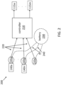
- FIG. 2 is a block diagram of an exemplary dynamic sensor network 200 according to one or more embodiments.
- the dynamic sensor network 200 may be in a spoke and hub arrangement.
- a controller 210 acts as the hub.
- the controller 210 may be part of the DCM 130, for example, with one or more processors and memory devices that facilitate obtaining data from one or more of the sensors 140 via communication lines 220 (i.e., spokes) and providing information to one or more output devices 115.
- the exemplary dynamic sensor network 200 is shown with sensors 140a through 140n (e.g., camera, infrared camera, proximity sensor, Geiger counter, rangefinder) while ports 155a through 155x are shown. That is, some ports 155 may be unused during a given mission.
- FIG. 2 also shows output devices 115a through 115m (e.g., audio, visual, haptic).
- one of the sensors 140 may be a camera coupled to a port 155 near the hand of the EMU 105. This camera may be used to see around objects in a cave or the like.
- the images provided as data over the communication line 220 corresponding to the data port 155 may be projected to an OLED display on the inner bubble of the helmet 110 as the output device 115.
- a sensor 140 may be a Geiger counter coupled to one of the ports 155.
- the radiation readings provided to the controller 210 over the corresponding communication line 220 may be checked by the controller 210 to determine if a threshold value has been crossed. If so, the controller 210 may provide an audible alert to an output device 115 that is a speaker or provide haptic feedback to an output device 115 that implements a vibration.
- the type of data provided by a given sensor 140 may determine the analysis performed by the controller 210, as well as the output provided to an output device 115.
- the data may be provided with an identifier or may be recognizable based on the content.
- the controller 210 may essentially implement a mapping of the processing that is appropriate for each data type. Input from the wearer of the EMU 105, provided via the DCM 130, for example, may affect the processing that is performed by the controller 210.
- the table below provides exemplary processing that may be performed based on the data obtained by the controller 210. The examples provided for explanatory purposes are not intended to limit additional sensors 140, processing by the controller 210, or additional output devices 115. Table 1. Exemplary inputs and outputs of a dynamic sensor network 200.
- controller 210 output to output device 115 image data from camera pass through or any specified image processing display to one or more display devices radiation level from Geiger counter compare with a predefined threshold value audio, video, haptic alert proximity (distance) from proximity sensor pass through or compare with a predefined threshold distance display distance to closest object or provide alert based on a distance below the predefined threshold distance range to an object from rangefinder pass through range display to one or more display devices
- a battery 230 of the EMU 105 may be a hub.
- the battery may be part of the PLSS 120, for example.
- One or more sensors 140 may be powered or charged via power lines 240 from the battery 230 to corresponding ports 155.
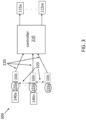
- FIG. 3 is a block diagram of an exemplary dynamic sensor network 300 according to one or more embodiments.
- FIG. 3 shows additional or alternate features as compared with the exemplary dynamic sensor network 200 shown in FIG. 2 .
- the fundamental components of the controller 210 and communication lines 220 from various ports 155 to which sensors 140 may couple is shown.
- each port 155 may include an optional microcontroller 310a through 310x (generally referred to as 310).
- 310 data from each sensor 140 that is coupled to a port 155 may be routed through a microcontroller 310 via a communication line 220 to the controller 210.
- redundant wired or wireless communication lines 320 may be included between ports or, more specifically, between microcontrollers 310. That is, sensors 140 may communicate data from a corresponding port 155 to another port 155 for relay to the controller 210 via a communication line 220 from the other port 155. This may be necessitated due to failure of the communication line 220 from the port 155 corresponding with the sensor 140, for example.
- microcontrollers 310 may communicate data obtained from a corresponding sensor 140 to another microcontroller 310. The data may be relayed to the controller 210 or may be combined with data from the sensor 140 corresponding to the other microcontroller 310 prior to being provided to the controller 210, for example.
Landscapes
- Engineering & Computer Science (AREA)
- Theoretical Computer Science (AREA)
- Computer Hardware Design (AREA)
- Computer Networks & Wireless Communication (AREA)
- Aviation & Aerospace Engineering (AREA)
- Medical Informatics (AREA)
- Signal Processing (AREA)
- Remote Sensing (AREA)
- General Health & Medical Sciences (AREA)
- Computing Systems (AREA)
- Human Computer Interaction (AREA)
- Physics & Mathematics (AREA)
- General Engineering & Computer Science (AREA)
- General Physics & Mathematics (AREA)
- Health & Medical Sciences (AREA)
- Arrangements For Transmission Of Measured Signals (AREA)
- Helmets And Other Head Coverings (AREA)
Abstract
Description
- Exemplary embodiments pertain to the art of atmospheric suit and, in particular, to a dynamic sensor network in an atmospheric suit.
- In some environments and applications, an atmospheric suit is used not only for protection against impacts but also to maintain a habitable environment. In a space application, for example, an extravehicular mobility unit (EMU), which includes a helmet and full body suit supplied by an oxygen tank, maintains an environment that sustains the astronaut.
- In one aspect, a system in an atmospheric suit includes a controller within the atmospheric suit. The system also includes a hub and spoke network arranged within the atmospheric suit. The controller is the hub of the network and each spoke of the network represents wiring that leads to one of a plurality of ports accessible from outside the atmospheric suit.
- In addition to one or more of the features described herein, the controller may obtain data from one or more sensors coupled to one or more of the plurality of ports.
- In addition to one or more of the features described herein, the one or more sensors may include a camera, a proximity sensor, a range finder, or a Geiger counter and the controller may process the data from the one or more sensors to obtain information.
- In addition to one or more of the features described herein, a wearer of the atmospheric suit may specify processing of the data.
- In addition to one or more of the features described herein, the controller may provide information based on the data to a wearer of the atmospheric suit as output to one or more output devices.
- In addition to one or more of the features described herein, the one or more output devices may include audio, video, or haptic output devices.
- In addition to one or more of the features described herein, one of the one or more sensors may be a camera, one of the one or more output devices may be a display device, and the controller may obtain images from the camera and provide the information based on the images for display to the wearer on the display device.
- In addition to one or more of the features described herein, the system may also include microcontrollers corresponding with one or more of the plurality of ports.
- In addition to one or more of the features described herein, the network may include redundant communication between two or more of the plurality of microcontroller or between two or more of the ports.
- In addition to one or more of the features described herein, the system may also include a cover on each of the plurality of ports.
- In another aspect, a method of assembling a system in an atmospheric suit includes configuring a controller within the atmospheric suit. The method also includes arranging a network as a hub and spoke network within the atmospheric suit. The controller is the hub of the network and each spoke of the network represents wiring that leads to one of a plurality of ports accessible from outside the atmospheric suit.
- In addition to one or more of the features described herein, the configuring the controller may include the controller obtaining data from one or more sensors coupled to one or more of the plurality of ports.
- In addition to one or more of the features described herein, the one or more sensors may include a camera, a proximity sensor, a range finder, or a Geiger counter and the configuring the controller may include the controller processing the data from the one or more sensors to obtain information.
- In addition to one or more of the features described herein, the configuring the controller may include the controller obtaining an indication of the processing of the data from a wearer of the atmospheric suit.
- In addition to one or more of the features described herein, the configuring the controller may include the controller providing information based on the data to a wearer of the atmospheric suit as output to one or more output devices.
- In addition to one or more of the features described herein, the one or more output devices may include audio, video, or haptic output devices.
- In addition to one or more of the features described herein, one of the one or more sensors may be a camera, one of the one or more output devices may be a display device, and the configuring the controller may include the controller obtaining images from the camera and providing the information based on the images for display to the wearer on the display device.
- In addition to one or more of the features described herein, the arranging the network may include disposing microcontrollers corresponding with one or more of the plurality of ports.
- In addition to one or more of the features described herein, the arranging the network may include configuring redundant communication between two or more of the plurality of microcontroller or between two or more of the ports.
- In addition to one or more of the features described herein, the method may also include disposing a cover on each of the plurality of ports.
- The following descriptions should not be considered limiting in any way. With reference to the accompanying drawings, like elements are numbered alike:
-
FIG. 1 shows an atmospheric suit that includes a dynamic sensor network according to one or more embodiments; -
FIG. 2 is a block diagram of an exemplary dynamic sensor network according to one or more embodiments; and -
FIG. 3 is a block diagram of another exemplary dynamic sensor network according to one or more embodiments. - A detailed description of one or more embodiments of the disclosed apparatus and method are presented herein by way of exemplification and not limitation with reference to the Figures.
- As previously noted, an atmospheric suit maintains a habitable environment for the wearer in different applications. In the exemplary space application, the atmospheric suit may be an EMU. While the atmospheric suit is essential in an otherwise uninhabitable environment, it can be bulky and restrict spatial awareness. For example, unlike a motorcycle helmet or the like, the helmet of the atmospheric suit is fixed such that a wearer moves their head without moving the helmet (i.e., the transparent portion of the helmet). Thus, looking to the side or behind requires moving the body (and, correspondingly, the atmospheric suit) to expose the side or back to the transparent portion of the helmet. In addition, depending on the nature and duration of an extravehicular mission, sensors may be needed for safety or data-gathering. These sensors may be difficult to carry and operate in the atmospheric suit.
- Embodiments of the systems and methods detailed herein relate to a dynamic sensor network in an atmospheric suit. The network may be structured in a hub and spoke configuration with a controller of the atmospheric suit acting as the hub. Each spoke may lead to a port accessible outside the atmospheric suit, and different sensors may be coupled to the port, as needed. According to alternative or additional embodiments, a battery of the atmospheric suit may act as the hub with the spokes facilitating charging of the sensors.
-
FIG. 1 shows an atmospheric suit 100 that includes a dynamic sensor network 200 (FIG. 2 ) according to one or more embodiments. The exemplary atmospheric suit 100 shown inFIG. 1 is an EMU 105. Systems that are affixed as part of the EMU 105 include a primary life support system (PLSS) 120 and a display and control module (DCM) 130. Thesesystems 120, 130, along with components of the EMU 105, create a habitable environment for a wearer performing extravehicular activity in space. While an EMU and a space application are specifically discussed for explanatory purposes, applications for the controller system architecture according to one or more embodiments may also include underwater (e.g., in an atmospheric diving suit), earth-based (e.g., in a hazmat suit or contamination suit), high-altitude (e.g., in a flight suit), and sub-surface environments. Generally, any suit that includes the helmet to maintain a habitable environment is referred to as an atmospheric suit. - The EMU 105 includes a helmet 110, shown with an exemplary inhelmet display as one
exemplary output device 115a and a speaker as anotherexemplary output device 115b (generally referred to as output device 115). The helmet 110 has a transparent inner bubble that maintains the environment in the EMU 105, as well as a transparent outer bubble that protects against impacts. The display device may include a screen on a swingarm that allows the screen to be raised to eye level for viewing or may include an organic light emitting diode (OLED) array. An OLED display device may be inside the helmet, with the inner bubble acting as a substrate, or may be in the gap between the inner and outer bubbles, with the outer bubble acting as the substrate. A display device may also be on a swingarm or otherwise affixed on the outside of the helmet 110. According to exemplary embodiments, the EMU 105 may include two or more display devices whose number and location is not intended to be limited by the discussion of exemplary embodiments. - The speaker may be inside the inner bubble or may include a diaphragm on the outside of the inner bubble that vibrates to produce an audio output. The numbers, types, and locations of speakers is not intended to be limited by the examples. Further, in addition to audio and visual output devices 115, haptic or combination output devices 115 may be provided in the EMU 105. The numbers, types, and locations of output devices 115 that provide information to the wearer of the EMU 105 are not intended to be limited by the discussion of specific examples.
- One or more sensors 140 (e.g., video/still camera, infrared camera, proximity sensor, Geiger counter, rangefinder) may dynamically be affixed to the EMU 105. Dynamic refers to the fact that the numbers and positions of
sensors 140 may be changed at any time, even during extravehicular activity. Twoexemplary sensors 140 are indicated inFIG. 1 . Also indicated is anunused port 155. While not visible, each of thesensors 140 is coupled to thedynamic sensor network 200 via aport 155. As the expanded view indicates, theport 155 may have acover 150 when unused to prevent dust or other particles from entering theport 155. InFIG. 1 , one sensor 140 (e.g., Geiger counter) is shown affixed to an arm of the EMU 105 and another sensor 140 (e.g., camera) is shown affixed at the hip. As shown, the camera may be angled down so that the path ahead of the EMU 105 may be viewed in real time on a display used as the output device 115 while walking. Thedynamic sensor network 200 that facilitates obtaining data from these andother sensors 140 and providing information via one or more output devices 115 is detailed with reference toFIG. 2 . -
FIG. 2 is a block diagram of an exemplarydynamic sensor network 200 according to one or more embodiments. As previously noted, thedynamic sensor network 200 may be in a spoke and hub arrangement. According to an exemplary embodiment, acontroller 210 acts as the hub. Thecontroller 210 may be part of the DCM 130, for example, with one or more processors and memory devices that facilitate obtaining data from one or more of thesensors 140 via communication lines 220 (i.e., spokes) and providing information to one or more output devices 115. The exemplarydynamic sensor network 200 is shown withsensors 140a through 140n (e.g., camera, infrared camera, proximity sensor, Geiger counter, rangefinder) whileports 155a through 155x are shown. That is, someports 155 may be unused during a given mission.FIG. 2 also showsoutput devices 115a through 115m (e.g., audio, visual, haptic). - For example, one of the
sensors 140 may be a camera coupled to aport 155 near the hand of the EMU 105. This camera may be used to see around objects in a cave or the like. The images provided as data over thecommunication line 220 corresponding to thedata port 155 may be projected to an OLED display on the inner bubble of the helmet 110 as the output device 115. As another example, asensor 140 may be a Geiger counter coupled to one of theports 155. The radiation readings provided to thecontroller 210 over thecorresponding communication line 220 may be checked by thecontroller 210 to determine if a threshold value has been crossed. If so, thecontroller 210 may provide an audible alert to an output device 115 that is a speaker or provide haptic feedback to an output device 115 that implements a vibration. - The type of data provided by a given
sensor 140 may determine the analysis performed by thecontroller 210, as well as the output provided to an output device 115. The data may be provided with an identifier or may be recognizable based on the content. Thecontroller 210 may essentially implement a mapping of the processing that is appropriate for each data type. Input from the wearer of the EMU 105, provided via the DCM 130, for example, may affect the processing that is performed by thecontroller 210. The table below provides exemplary processing that may be performed based on the data obtained by thecontroller 210. The examples provided for explanatory purposes are not intended to limitadditional sensors 140, processing by thecontroller 210, or additional output devices 115.Table 1. Exemplary inputs and outputs of a dynamic sensor network 200.data from sensor 140processing performed by controller 210output to output device 115 image data from camera pass through or any specified image processing display to one or more display devices radiation level from Geiger counter compare with a predefined threshold value audio, video, haptic alert proximity (distance) from proximity sensor pass through or compare with a predefined threshold distance display distance to closest object or provide alert based on a distance below the predefined threshold distance range to an object from rangefinder pass through range display to one or more display devices - According to an alternative or additional embodiment, a
battery 230 of the EMU 105 may be a hub. The battery may be part of thePLSS 120, for example. One ormore sensors 140 may be powered or charged viapower lines 240 from thebattery 230 to correspondingports 155. -
FIG. 3 is a block diagram of an exemplarydynamic sensor network 300 according to one or more embodiments.FIG. 3 shows additional or alternate features as compared with the exemplarydynamic sensor network 200 shown inFIG. 2 . The fundamental components of thecontroller 210 andcommunication lines 220 fromvarious ports 155 to whichsensors 140 may couple is shown. As shown inFIG. 3 , eachport 155 may include anoptional microcontroller 310a through 310x (generally referred to as 310). Thus, data from eachsensor 140 that is coupled to aport 155 may be routed through a microcontroller 310 via acommunication line 220 to thecontroller 210. - Additionally or alternatively, redundant wired or
wireless communication lines 320 may be included between ports or, more specifically, between microcontrollers 310. That is,sensors 140 may communicate data from acorresponding port 155 to anotherport 155 for relay to thecontroller 210 via acommunication line 220 from theother port 155. This may be necessitated due to failure of thecommunication line 220 from theport 155 corresponding with thesensor 140, for example. Alternatively, microcontrollers 310 may communicate data obtained from acorresponding sensor 140 to another microcontroller 310. The data may be relayed to thecontroller 210 or may be combined with data from thesensor 140 corresponding to the other microcontroller 310 prior to being provided to thecontroller 210, for example. - The terminology used herein is for the purpose of describing particular embodiments only and is not intended to be limiting of the present disclosure. As used herein, the singular forms "a", "an" and "the" are intended to include the plural forms as well, unless the context clearly indicates otherwise. It will be further understood that the terms "comprises" and/or "comprising," when used in this specification, specify the presence of stated features, integers, steps, operations, elements, and/or components, but do not preclude the presence or addition of one or more other features, integers, steps, operations, element components, and/or groups thereof.
- While the present disclosure has been described with reference to an exemplary embodiment or embodiments, it will be understood by those skilled in the art that various changes may be made without departing from the scope of the invention as defined by the claims. In addition, many modifications may be made to adapt a particular situation or material to the teachings of the present disclosure without departing from the scope of the claims. Therefore, it is intended that the present disclosure not be limited to the particular embodiment disclosed as the best mode contemplated for carrying out this present disclosure, but that the present disclosure will include all embodiments falling within the scope of the claims.
Claims (15)
- A system in an atmospheric suit, the system comprising:a controller (210) within the atmospheric suit (100); anda network (200) configured as a hub and spoke network arranged within the atmospheric suit, wherein the controller is the hub of the network, each spoke of the network represents wiring that leads to one of a plurality of ports (155) accessible from outside the atmospheric suit.
- The system according to claim 1, wherein the controller is configured to obtain data from one or more sensors (140) coupled to one or more of the plurality of ports.
- The system according to claim 2, wherein the one or more sensors includes a camera, a proximity sensor, a range finder, or a Geiger counter and the controller is configured to process the data from the one or more sensors to obtain information.
- The system according to claim 3, wherein a wearer of the atmospheric suit specifies processing of the data.
- The system according to claim 3, wherein the controller is configured to provide information based on the data to a wearer of the atmospheric suit as output to one or more output devices (115), and optionally wherein the one or more output devices include audio, video, or haptic output devices.
- The system according to claim 5, wherein one of the one or more sensors is a camera, one of the one or more output devices is a display device, and the controller is configured to obtain images from the camera and provide the information based on the images for display to the wearer on the display device.
- The system according to any preceding claim, further comprising microcontrollers (310) corresponding with one or more of the plurality of ports, and optionally wherein the network includes redundant communication between two or more of the plurality of microcontroller or between two or more of the ports.
- The system according to any preceding claim, further comprising a cover (150) on each of the plurality of ports.
- A method of assembling a system in an atmospheric suit, the method comprising:configuring a controller (210) within the atmospheric suit (100); andarranging a network (200) configured as a hub and spoke network within the atmospheric suit, wherein the controller is the hub of the network, each spoke of the network represents wiring that leads to one of a plurality of ports (155) accessible from outside the atmospheric suit.
- The method according to claim 9, wherein the configuring the controller includes the controller obtaining data from one or more sensors (140) coupled to one or more of the plurality of ports.
- The method according to claim 10, wherein the one or more sensors includes a camera, a proximity sensor, a range finder, or a Geiger counter and the configuring the controller includes the controller processing the data from the one or more sensors to obtain information.
- The method according to claim 11, wherein the configuring the controller includes the controller obtaining an indication of the processing of the data from a wearer of the atmospheric suit, and/or wherein the configuring the controller includes the controller providing information based on the data to a wearer of the atmospheric suit as output to one or more output devices (115).
- The method according to claim 12, wherein the one or more output devices include audio, video, or haptic output devices, and optionally wherein one of the one or more sensors is a camera, one of the one or more output devices is a display device, and the configuring the controller includes the controller obtaining images from the camera and providing the information based on the images for display to the wearer on the display device.
- The method according to any of claims 9 to 13, wherein the arranging the network includes disposing microcontrollers (310) corresponding with one or more of the plurality of ports, and optionally wherein the arranging the network includes configuring redundant communication between two or more of the plurality of microcontroller or between two or more of the ports.
- The method according to any of claims 9 to 14, further comprising disposing a cover (150) on each of the plurality of ports.
Applications Claiming Priority (1)
| Application Number | Priority Date | Filing Date | Title |
|---|---|---|---|
| US17/571,674 US11716386B1 (en) | 2022-01-10 | 2022-01-10 | Dynamic sensor network in atmospheric suit |
Publications (2)
| Publication Number | Publication Date |
|---|---|
| EP4210342A1 true EP4210342A1 (en) | 2023-07-12 |
| EP4210342B1 EP4210342B1 (en) | 2025-05-14 |
Family
ID=84901587
Family Applications (1)
| Application Number | Title | Priority Date | Filing Date |
|---|---|---|---|
| EP23150949.8A Active EP4210342B1 (en) | 2022-01-10 | 2023-01-10 | Dynamic sensor network in atmospheric suit |
Country Status (2)
| Country | Link |
|---|---|
| US (1) | US11716386B1 (en) |
| EP (1) | EP4210342B1 (en) |
Citations (1)
| Publication number | Priority date | Publication date | Assignee | Title |
|---|---|---|---|---|
| US7190636B1 (en) * | 2005-02-25 | 2007-03-13 | Depaola Victor R | Diving suit and environmental detecting system |
Family Cites Families (9)
| Publication number | Priority date | Publication date | Assignee | Title |
|---|---|---|---|---|
| US8692886B2 (en) | 2007-10-31 | 2014-04-08 | Timothy James Ennis | Multidirectional video capture assembly |
| US10944140B2 (en) * | 2014-01-15 | 2021-03-09 | Lat Enterprises, Inc. | Wearable and replaceable pouch or skin for holding a portable battery pack |
| US11171509B2 (en) * | 2016-02-25 | 2021-11-09 | California Institute Of Technology | Adaptive charging network using adaptive charging stations for electric vehicles |
| US20180332219A1 (en) | 2017-05-10 | 2018-11-15 | Fotonation Limited | Wearable vision system and method of monitoring a region |
| US11954486B2 (en) * | 2017-06-05 | 2024-04-09 | Umajin Inc. | Location tracking system and methods |
| US20210223557A1 (en) | 2019-08-21 | 2021-07-22 | Hypergiant Industries, Inc. | Active display helmet |
| US11883832B2 (en) * | 2020-03-17 | 2024-01-30 | The Boeing Company | Releasable dust mitigation covering |
| US11910864B2 (en) * | 2020-05-01 | 2024-02-27 | Rockwell Collins, Inc. | LED information cueing apparatus for spacesuit helmet |
| US11740699B2 (en) * | 2020-06-11 | 2023-08-29 | Angelina Dong | Tactile feedback glove |
-
2022
- 2022-01-10 US US17/571,674 patent/US11716386B1/en active Active
-
2023
- 2023-01-10 EP EP23150949.8A patent/EP4210342B1/en active Active
Patent Citations (1)
| Publication number | Priority date | Publication date | Assignee | Title |
|---|---|---|---|---|
| US7190636B1 (en) * | 2005-02-25 | 2007-03-13 | Depaola Victor R | Diving suit and environmental detecting system |
Also Published As
| Publication number | Publication date |
|---|---|
| US11716386B1 (en) | 2023-08-01 |
| EP4210342B1 (en) | 2025-05-14 |
| US20230224364A1 (en) | 2023-07-13 |
Similar Documents
| Publication | Publication Date | Title |
|---|---|---|
| CN110494792B (en) | Visual tracking of peripheral devices | |
| CN103620527B (en) | Head-mounted computer that uses motion and voice commands to control information displays and remote devices | |
| US20220376531A1 (en) | Charging apparatus | |
| US10178457B1 (en) | Audio output assembly for a head-mounted display | |
| US20210109354A1 (en) | Self-contained breathing apparatus having face piece vision system | |
| ATE360190T1 (en) | AIR RECONNAISSANCE SYSTEM | |
| CN116929323A (en) | Sensor unit, moving object positioning device, and moving object | |
| KR102436036B1 (en) | Method And Apparatus for Searching Survivor | |
| US20160253561A1 (en) | Face mounted extreme environment thermal sensor | |
| KR20210141960A (en) | High-compliance microspeakers for vibration dampening in wearable audio devices | |
| EP3650975A1 (en) | Mobile image pickup device | |
| KR20210058989A (en) | SCBA facemask assembly with accelerometer to extend battery life of electrical components | |
| EP4210342B1 (en) | Dynamic sensor network in atmospheric suit | |
| CN112823083A (en) | Configurable and interactive robotic system | |
| CN212181167U (en) | Split type AR intelligence glasses of function enhancement mode | |
| JPWO2020110292A1 (en) | Display control system, display control device and display control method | |
| WO2016135448A1 (en) | Emergency guidance system and method | |
| JP6821864B2 (en) | Display control system, display control device and display control method | |
| US20230166874A1 (en) | Atmospheric suit helmet display and display-based control | |
| WO2021166140A1 (en) | Drone |
Legal Events
| Date | Code | Title | Description |
|---|---|---|---|
| PUAI | Public reference made under article 153(3) epc to a published international application that has entered the european phase |
Free format text: ORIGINAL CODE: 0009012 |
|
| STAA | Information on the status of an ep patent application or granted ep patent |
Free format text: STATUS: THE APPLICATION HAS BEEN PUBLISHED |
|
| AK | Designated contracting states |
Kind code of ref document: A1 Designated state(s): AL AT BE BG CH CY CZ DE DK EE ES FI FR GB GR HR HU IE IS IT LI LT LU LV MC ME MK MT NL NO PL PT RO RS SE SI SK SM TR |
|
| STAA | Information on the status of an ep patent application or granted ep patent |
Free format text: STATUS: REQUEST FOR EXAMINATION WAS MADE |
|
| 17P | Request for examination filed |
Effective date: 20240112 |
|
| RBV | Designated contracting states (corrected) |
Designated state(s): AL AT BE BG CH CY CZ DE DK EE ES FI FR GB GR HR HU IE IS IT LI LT LU LV MC ME MK MT NL NO PL PT RO RS SE SI SK SM TR |
|
| GRAP | Despatch of communication of intention to grant a patent |
Free format text: ORIGINAL CODE: EPIDOSNIGR1 |
|
| STAA | Information on the status of an ep patent application or granted ep patent |
Free format text: STATUS: GRANT OF PATENT IS INTENDED |
|
| INTG | Intention to grant announced |
Effective date: 20241217 |
|
| GRAS | Grant fee paid |
Free format text: ORIGINAL CODE: EPIDOSNIGR3 |
|
| GRAA | (expected) grant |
Free format text: ORIGINAL CODE: 0009210 |
|
| STAA | Information on the status of an ep patent application or granted ep patent |
Free format text: STATUS: THE PATENT HAS BEEN GRANTED |
|
| AK | Designated contracting states |
Kind code of ref document: B1 Designated state(s): AL AT BE BG CH CY CZ DE DK EE ES FI FR GB GR HR HU IE IS IT LI LT LU LV MC ME MK MT NL NO PL PT RO RS SE SI SK SM TR |
|
| REG | Reference to a national code |
Ref country code: GB Ref legal event code: FG4D |
|
| REG | Reference to a national code |
Ref country code: CH Ref legal event code: EP |
|
| REG | Reference to a national code |
Ref country code: DE Ref legal event code: R096 Ref document number: 602023003396 Country of ref document: DE |
|
| REG | Reference to a national code |
Ref country code: IE Ref legal event code: FG4D |
|
| REG | Reference to a national code |
Ref country code: NL Ref legal event code: MP Effective date: 20250514 |
|
| PG25 | Lapsed in a contracting state [announced via postgrant information from national office to epo] |
Ref country code: FI Free format text: LAPSE BECAUSE OF FAILURE TO SUBMIT A TRANSLATION OF THE DESCRIPTION OR TO PAY THE FEE WITHIN THE PRESCRIBED TIME-LIMIT Effective date: 20250514 Ref country code: PT Free format text: LAPSE BECAUSE OF FAILURE TO SUBMIT A TRANSLATION OF THE DESCRIPTION OR TO PAY THE FEE WITHIN THE PRESCRIBED TIME-LIMIT Effective date: 20250915 Ref country code: ES Free format text: LAPSE BECAUSE OF FAILURE TO SUBMIT A TRANSLATION OF THE DESCRIPTION OR TO PAY THE FEE WITHIN THE PRESCRIBED TIME-LIMIT Effective date: 20250514 |
|
| REG | Reference to a national code |
Ref country code: LT Ref legal event code: MG9D |
|
| PG25 | Lapsed in a contracting state [announced via postgrant information from national office to epo] |
Ref country code: NO Free format text: LAPSE BECAUSE OF FAILURE TO SUBMIT A TRANSLATION OF THE DESCRIPTION OR TO PAY THE FEE WITHIN THE PRESCRIBED TIME-LIMIT Effective date: 20250814 Ref country code: GR Free format text: LAPSE BECAUSE OF FAILURE TO SUBMIT A TRANSLATION OF THE DESCRIPTION OR TO PAY THE FEE WITHIN THE PRESCRIBED TIME-LIMIT Effective date: 20250815 |
|
| PG25 | Lapsed in a contracting state [announced via postgrant information from national office to epo] |
Ref country code: NL Free format text: LAPSE BECAUSE OF FAILURE TO SUBMIT A TRANSLATION OF THE DESCRIPTION OR TO PAY THE FEE WITHIN THE PRESCRIBED TIME-LIMIT Effective date: 20250514 Ref country code: PL Free format text: LAPSE BECAUSE OF FAILURE TO SUBMIT A TRANSLATION OF THE DESCRIPTION OR TO PAY THE FEE WITHIN THE PRESCRIBED TIME-LIMIT Effective date: 20250514 |
|
| REG | Reference to a national code |
Ref country code: AT Ref legal event code: MK05 Ref document number: 1795828 Country of ref document: AT Kind code of ref document: T Effective date: 20250514 |
|
| PG25 | Lapsed in a contracting state [announced via postgrant information from national office to epo] |
Ref country code: BG Free format text: LAPSE BECAUSE OF FAILURE TO SUBMIT A TRANSLATION OF THE DESCRIPTION OR TO PAY THE FEE WITHIN THE PRESCRIBED TIME-LIMIT Effective date: 20250514 |
|
| PG25 | Lapsed in a contracting state [announced via postgrant information from national office to epo] |
Ref country code: HR Free format text: LAPSE BECAUSE OF FAILURE TO SUBMIT A TRANSLATION OF THE DESCRIPTION OR TO PAY THE FEE WITHIN THE PRESCRIBED TIME-LIMIT Effective date: 20250514 |
|
| PG25 | Lapsed in a contracting state [announced via postgrant information from national office to epo] |
Ref country code: AT Free format text: LAPSE BECAUSE OF FAILURE TO SUBMIT A TRANSLATION OF THE DESCRIPTION OR TO PAY THE FEE WITHIN THE PRESCRIBED TIME-LIMIT Effective date: 20250514 |
|
| PG25 | Lapsed in a contracting state [announced via postgrant information from national office to epo] |
Ref country code: RS Free format text: LAPSE BECAUSE OF FAILURE TO SUBMIT A TRANSLATION OF THE DESCRIPTION OR TO PAY THE FEE WITHIN THE PRESCRIBED TIME-LIMIT Effective date: 20250814 |
|
| PG25 | Lapsed in a contracting state [announced via postgrant information from national office to epo] |
Ref country code: IS Free format text: LAPSE BECAUSE OF FAILURE TO SUBMIT A TRANSLATION OF THE DESCRIPTION OR TO PAY THE FEE WITHIN THE PRESCRIBED TIME-LIMIT Effective date: 20250914 |
|
| PG25 | Lapsed in a contracting state [announced via postgrant information from national office to epo] |
Ref country code: LV Free format text: LAPSE BECAUSE OF FAILURE TO SUBMIT A TRANSLATION OF THE DESCRIPTION OR TO PAY THE FEE WITHIN THE PRESCRIBED TIME-LIMIT Effective date: 20250514 |
|
| PG25 | Lapsed in a contracting state [announced via postgrant information from national office to epo] |
Ref country code: DK Free format text: LAPSE BECAUSE OF FAILURE TO SUBMIT A TRANSLATION OF THE DESCRIPTION OR TO PAY THE FEE WITHIN THE PRESCRIBED TIME-LIMIT Effective date: 20250514 Ref country code: SM Free format text: LAPSE BECAUSE OF FAILURE TO SUBMIT A TRANSLATION OF THE DESCRIPTION OR TO PAY THE FEE WITHIN THE PRESCRIBED TIME-LIMIT Effective date: 20250514 |
|
| PGFP | Annual fee paid to national office [announced via postgrant information from national office to epo] |
Ref country code: FR Payment date: 20251217 Year of fee payment: 4 |
|
| PG25 | Lapsed in a contracting state [announced via postgrant information from national office to epo] |
Ref country code: CZ Free format text: LAPSE BECAUSE OF FAILURE TO SUBMIT A TRANSLATION OF THE DESCRIPTION OR TO PAY THE FEE WITHIN THE PRESCRIBED TIME-LIMIT Effective date: 20250514 |
|
| PG25 | Lapsed in a contracting state [announced via postgrant information from national office to epo] |
Ref country code: EE Free format text: LAPSE BECAUSE OF FAILURE TO SUBMIT A TRANSLATION OF THE DESCRIPTION OR TO PAY THE FEE WITHIN THE PRESCRIBED TIME-LIMIT Effective date: 20250514 |
|
| PG25 | Lapsed in a contracting state [announced via postgrant information from national office to epo] |
Ref country code: SK Free format text: LAPSE BECAUSE OF FAILURE TO SUBMIT A TRANSLATION OF THE DESCRIPTION OR TO PAY THE FEE WITHIN THE PRESCRIBED TIME-LIMIT Effective date: 20250514 |
|
| PG25 | Lapsed in a contracting state [announced via postgrant information from national office to epo] |
Ref country code: IT Free format text: LAPSE BECAUSE OF FAILURE TO SUBMIT A TRANSLATION OF THE DESCRIPTION OR TO PAY THE FEE WITHIN THE PRESCRIBED TIME-LIMIT Effective date: 20250514 |
|
| REG | Reference to a national code |
Ref country code: DE Ref legal event code: R097 Ref document number: 602023003396 Country of ref document: DE |
|
| PLBE | No opposition filed within time limit |
Free format text: ORIGINAL CODE: 0009261 |
|
| STAA | Information on the status of an ep patent application or granted ep patent |
Free format text: STATUS: NO OPPOSITION FILED WITHIN TIME LIMIT |
|
| REG | Reference to a national code |
Ref country code: CH Ref legal event code: L10 Free format text: ST27 STATUS EVENT CODE: U-0-0-L10-L00 (AS PROVIDED BY THE NATIONAL OFFICE) Effective date: 20260325 |
|
| 26N | No opposition filed |
Effective date: 20260217 |