EP4210152A1 - Battery module and battery pack including same - Google Patents
Battery module and battery pack including same Download PDFInfo
- Publication number
- EP4210152A1 EP4210152A1 EP22775934.7A EP22775934A EP4210152A1 EP 4210152 A1 EP4210152 A1 EP 4210152A1 EP 22775934 A EP22775934 A EP 22775934A EP 4210152 A1 EP4210152 A1 EP 4210152A1
- Authority
- EP
- European Patent Office
- Prior art keywords
- battery cell
- cell stack
- battery
- recessed part
- frame
- Prior art date
- Legal status (The legal status is an assumption and is not a legal conclusion. Google has not performed a legal analysis and makes no representation as to the accuracy of the status listed.)
- Pending
Links
- 238000001816 cooling Methods 0.000 claims abstract description 65
- 239000003507 refrigerant Substances 0.000 claims abstract description 41
- 238000007599 discharging Methods 0.000 claims abstract description 6
- 230000008878 coupling Effects 0.000 claims description 12
- 238000010168 coupling process Methods 0.000 claims description 12
- 238000005859 coupling reaction Methods 0.000 claims description 12
- 239000011347 resin Substances 0.000 description 8
- 229920005989 resin Polymers 0.000 description 8
- WHXSMMKQMYFTQS-UHFFFAOYSA-N Lithium Chemical compound [Li] WHXSMMKQMYFTQS-UHFFFAOYSA-N 0.000 description 6
- 229910052744 lithium Inorganic materials 0.000 description 6
- 238000000034 method Methods 0.000 description 6
- 238000007789 sealing Methods 0.000 description 5
- PXHVJJICTQNCMI-UHFFFAOYSA-N Nickel Chemical compound [Ni] PXHVJJICTQNCMI-UHFFFAOYSA-N 0.000 description 4
- 238000010586 diagram Methods 0.000 description 4
- 239000000463 material Substances 0.000 description 4
- 230000008901 benefit Effects 0.000 description 3
- 230000000694 effects Effects 0.000 description 3
- 239000006183 anode active material Substances 0.000 description 2
- 239000006182 cathode active material Substances 0.000 description 2
- 229910052751 metal Inorganic materials 0.000 description 2
- 239000002184 metal Substances 0.000 description 2
- 229910052759 nickel Inorganic materials 0.000 description 2
- 238000003825 pressing Methods 0.000 description 2
- 230000008569 process Effects 0.000 description 2
- JOYRKODLDBILNP-UHFFFAOYSA-N Ethyl urethane Chemical compound CCOC(N)=O JOYRKODLDBILNP-UHFFFAOYSA-N 0.000 description 1
- UFHFLCQGNIYNRP-UHFFFAOYSA-N Hydrogen Chemical compound [H][H] UFHFLCQGNIYNRP-UHFFFAOYSA-N 0.000 description 1
- 206010071232 Protuberant ear Diseases 0.000 description 1
- NIXOWILDQLNWCW-UHFFFAOYSA-N acrylic acid group Chemical group C(C=C)(=O)O NIXOWILDQLNWCW-UHFFFAOYSA-N 0.000 description 1
- 238000003915 air pollution Methods 0.000 description 1
- 229910052782 aluminium Inorganic materials 0.000 description 1
- XAGFODPZIPBFFR-UHFFFAOYSA-N aluminium Chemical compound [Al] XAGFODPZIPBFFR-UHFFFAOYSA-N 0.000 description 1
- 238000005452 bending Methods 0.000 description 1
- OJIJEKBXJYRIBZ-UHFFFAOYSA-N cadmium nickel Chemical compound [Ni].[Cd] OJIJEKBXJYRIBZ-UHFFFAOYSA-N 0.000 description 1
- 239000003575 carbonaceous material Substances 0.000 description 1
- 239000000498 cooling water Substances 0.000 description 1
- 230000006866 deterioration Effects 0.000 description 1
- 239000008151 electrolyte solution Substances 0.000 description 1
- 238000005516 engineering process Methods 0.000 description 1
- 230000001747 exhibiting effect Effects 0.000 description 1
- 239000002803 fossil fuel Substances 0.000 description 1
- 230000006870 function Effects 0.000 description 1
- 230000005484 gravity Effects 0.000 description 1
- 229910052739 hydrogen Inorganic materials 0.000 description 1
- 239000001257 hydrogen Substances 0.000 description 1
- 230000003446 memory effect Effects 0.000 description 1
- 238000012986 modification Methods 0.000 description 1
- 230000004048 modification Effects 0.000 description 1
- QELJHCBNGDEXLD-UHFFFAOYSA-N nickel zinc Chemical compound [Ni].[Zn] QELJHCBNGDEXLD-UHFFFAOYSA-N 0.000 description 1
- 230000001151 other effect Effects 0.000 description 1
- 229920001296 polysiloxane Polymers 0.000 description 1
- 239000000243 solution Substances 0.000 description 1
Images


Classifications
-
- H—ELECTRICITY
- H01—ELECTRIC ELEMENTS
- H01M—PROCESSES OR MEANS, e.g. BATTERIES, FOR THE DIRECT CONVERSION OF CHEMICAL ENERGY INTO ELECTRICAL ENERGY
- H01M10/00—Secondary cells; Manufacture thereof
- H01M10/60—Heating or cooling; Temperature control
- H01M10/65—Means for temperature control structurally associated with the cells
- H01M10/655—Solid structures for heat exchange or heat conduction
- H01M10/6556—Solid parts with flow channel passages or pipes for heat exchange
-
- H—ELECTRICITY
- H01—ELECTRIC ELEMENTS
- H01M—PROCESSES OR MEANS, e.g. BATTERIES, FOR THE DIRECT CONVERSION OF CHEMICAL ENERGY INTO ELECTRICAL ENERGY
- H01M10/00—Secondary cells; Manufacture thereof
- H01M10/60—Heating or cooling; Temperature control
- H01M10/65—Means for temperature control structurally associated with the cells
- H01M10/656—Means for temperature control structurally associated with the cells characterised by the type of heat-exchange fluid
- H01M10/6567—Liquids
- H01M10/6568—Liquids characterised by flow circuits, e.g. loops, located externally to the cells or cell casings
-
- H—ELECTRICITY
- H01—ELECTRIC ELEMENTS
- H01M—PROCESSES OR MEANS, e.g. BATTERIES, FOR THE DIRECT CONVERSION OF CHEMICAL ENERGY INTO ELECTRICAL ENERGY
- H01M10/00—Secondary cells; Manufacture thereof
- H01M10/42—Methods or arrangements for servicing or maintenance of secondary cells or secondary half-cells
- H01M10/4207—Methods or arrangements for servicing or maintenance of secondary cells or secondary half-cells for several batteries or cells simultaneously or sequentially
-
- H—ELECTRICITY
- H01—ELECTRIC ELEMENTS
- H01M—PROCESSES OR MEANS, e.g. BATTERIES, FOR THE DIRECT CONVERSION OF CHEMICAL ENERGY INTO ELECTRICAL ENERGY
- H01M10/00—Secondary cells; Manufacture thereof
- H01M10/60—Heating or cooling; Temperature control
- H01M10/61—Types of temperature control
- H01M10/613—Cooling or keeping cold
-
- H—ELECTRICITY
- H01—ELECTRIC ELEMENTS
- H01M—PROCESSES OR MEANS, e.g. BATTERIES, FOR THE DIRECT CONVERSION OF CHEMICAL ENERGY INTO ELECTRICAL ENERGY
- H01M10/00—Secondary cells; Manufacture thereof
- H01M10/60—Heating or cooling; Temperature control
- H01M10/62—Heating or cooling; Temperature control specially adapted for specific applications
- H01M10/625—Vehicles
-
- H—ELECTRICITY
- H01—ELECTRIC ELEMENTS
- H01M—PROCESSES OR MEANS, e.g. BATTERIES, FOR THE DIRECT CONVERSION OF CHEMICAL ENERGY INTO ELECTRICAL ENERGY
- H01M10/00—Secondary cells; Manufacture thereof
- H01M10/60—Heating or cooling; Temperature control
- H01M10/65—Means for temperature control structurally associated with the cells
- H01M10/655—Solid structures for heat exchange or heat conduction
- H01M10/6554—Rods or plates
-
- H—ELECTRICITY
- H01—ELECTRIC ELEMENTS
- H01M—PROCESSES OR MEANS, e.g. BATTERIES, FOR THE DIRECT CONVERSION OF CHEMICAL ENERGY INTO ELECTRICAL ENERGY
- H01M10/00—Secondary cells; Manufacture thereof
- H01M10/60—Heating or cooling; Temperature control
- H01M10/65—Means for temperature control structurally associated with the cells
- H01M10/656—Means for temperature control structurally associated with the cells characterised by the type of heat-exchange fluid
- H01M10/6567—Liquids
-
- H—ELECTRICITY
- H01—ELECTRIC ELEMENTS
- H01M—PROCESSES OR MEANS, e.g. BATTERIES, FOR THE DIRECT CONVERSION OF CHEMICAL ENERGY INTO ELECTRICAL ENERGY
- H01M50/00—Constructional details or processes of manufacture of the non-active parts of electrochemical cells other than fuel cells, e.g. hybrid cells
- H01M50/20—Mountings; Secondary casings or frames; Racks, modules or packs; Suspension devices; Shock absorbers; Transport or carrying devices; Holders
- H01M50/204—Racks, modules or packs for multiple batteries or multiple cells
- H01M50/207—Racks, modules or packs for multiple batteries or multiple cells characterised by their shape
- H01M50/209—Racks, modules or packs for multiple batteries or multiple cells characterised by their shape adapted for prismatic or rectangular cells
-
- H—ELECTRICITY
- H01—ELECTRIC ELEMENTS
- H01M—PROCESSES OR MEANS, e.g. BATTERIES, FOR THE DIRECT CONVERSION OF CHEMICAL ENERGY INTO ELECTRICAL ENERGY
- H01M50/00—Constructional details or processes of manufacture of the non-active parts of electrochemical cells other than fuel cells, e.g. hybrid cells
- H01M50/20—Mountings; Secondary casings or frames; Racks, modules or packs; Suspension devices; Shock absorbers; Transport or carrying devices; Holders
- H01M50/204—Racks, modules or packs for multiple batteries or multiple cells
- H01M50/207—Racks, modules or packs for multiple batteries or multiple cells characterised by their shape
- H01M50/211—Racks, modules or packs for multiple batteries or multiple cells characterised by their shape adapted for pouch cells
-
- H—ELECTRICITY
- H01—ELECTRIC ELEMENTS
- H01M—PROCESSES OR MEANS, e.g. BATTERIES, FOR THE DIRECT CONVERSION OF CHEMICAL ENERGY INTO ELECTRICAL ENERGY
- H01M50/00—Constructional details or processes of manufacture of the non-active parts of electrochemical cells other than fuel cells, e.g. hybrid cells
- H01M50/20—Mountings; Secondary casings or frames; Racks, modules or packs; Suspension devices; Shock absorbers; Transport or carrying devices; Holders
- H01M50/271—Lids or covers for the racks or secondary casings
-
- H—ELECTRICITY
- H01—ELECTRIC ELEMENTS
- H01M—PROCESSES OR MEANS, e.g. BATTERIES, FOR THE DIRECT CONVERSION OF CHEMICAL ENERGY INTO ELECTRICAL ENERGY
- H01M50/00—Constructional details or processes of manufacture of the non-active parts of electrochemical cells other than fuel cells, e.g. hybrid cells
- H01M50/20—Mountings; Secondary casings or frames; Racks, modules or packs; Suspension devices; Shock absorbers; Transport or carrying devices; Holders
- H01M50/296—Mountings; Secondary casings or frames; Racks, modules or packs; Suspension devices; Shock absorbers; Transport or carrying devices; Holders characterised by terminals of battery packs
-
- H—ELECTRICITY
- H01—ELECTRIC ELEMENTS
- H01M—PROCESSES OR MEANS, e.g. BATTERIES, FOR THE DIRECT CONVERSION OF CHEMICAL ENERGY INTO ELECTRICAL ENERGY
- H01M10/00—Secondary cells; Manufacture thereof
- H01M10/60—Heating or cooling; Temperature control
- H01M10/64—Heating or cooling; Temperature control characterised by the shape of the cells
- H01M10/647—Prismatic or flat cells, e.g. pouch cells
-
- H—ELECTRICITY
- H01—ELECTRIC ELEMENTS
- H01M—PROCESSES OR MEANS, e.g. BATTERIES, FOR THE DIRECT CONVERSION OF CHEMICAL ENERGY INTO ELECTRICAL ENERGY
- H01M2220/00—Batteries for particular applications
- H01M2220/20—Batteries in motive systems, e.g. vehicle, ship, plane
-
- Y—GENERAL TAGGING OF NEW TECHNOLOGICAL DEVELOPMENTS; GENERAL TAGGING OF CROSS-SECTIONAL TECHNOLOGIES SPANNING OVER SEVERAL SECTIONS OF THE IPC; TECHNICAL SUBJECTS COVERED BY FORMER USPC CROSS-REFERENCE ART COLLECTIONS [XRACs] AND DIGESTS
- Y02—TECHNOLOGIES OR APPLICATIONS FOR MITIGATION OR ADAPTATION AGAINST CLIMATE CHANGE
- Y02E—REDUCTION OF GREENHOUSE GAS [GHG] EMISSIONS, RELATED TO ENERGY GENERATION, TRANSMISSION OR DISTRIBUTION
- Y02E60/00—Enabling technologies; Technologies with a potential or indirect contribution to GHG emissions mitigation
- Y02E60/10—Energy storage using batteries
Definitions
- the present disclosure relates to a battery module and a battery pack including the same, and more particularly to a battery module having improved space utilization and cooling efficiency and a battery pack including the same.
- chargeable/dischargeable secondary batteries are used as a power source for an electric vehicle (EV), a hybrid electric vehicle (HEV), a plug-in hybrid electric vehicle (P-HEV) and the like, in an attempt to solve air pollution and the like caused by existing gasoline vehicles using fossil fuel. Therefore, the demand for development of the secondary battery is growing.
- EV electric vehicle
- HEV hybrid electric vehicle
- P-HEV plug-in hybrid electric vehicle
- the lithium secondary battery has come into the spotlight because they have advantages, for example, hardly exhibiting memory effects compared to nickel-based secondary batteries and thus being freely charged and discharged, and having very low self-discharge rate and high energy density.
- Such lithium secondary battery mainly uses a lithium-based oxide and a carbonaceous material as a cathode active material and an anode active material, respectively.
- the lithium secondary battery includes an electrode assembly in which a cathode plate and an anode plate, each being coated with the cathode active material and the anode active material, are arranged with a separator being interposed between them, and a battery case which seals and houses the electrode assembly together with an electrolytic solution.
- the lithium secondary battery may be classified based on the shape of the exterior material into a can-type secondary battery in which the electrode assembly is mounted in a metal can, and a pouch-type secondary battery in which the electrode assembly is mounted in a pouch of an aluminum laminate sheet.
- a battery module in which a large number of battery cells are electrically connected is used.
- a large number of battery cells are connected to each other in series or parallel to form a cell assembly, thereby improving capacity and output.
- One or more battery modules can be mounted together with various control and protection systems such as a BDU(battery disconnect unit), a BMS (battery management system) and a cooling system to form a battery pack.
- a battery module includes an upper battery cell stack and a lower battery cell stack in which a plurality of battery cells are stacked; a cooling flow path located between the upper battery cell stack and the lower battery cell stack; and a module frame in which the upper battery cell stack and the lower battery cell stack are housed.
- An inlet port for supplying a refrigerant to the cooling flow path and an outlet port for discharging the refrigerant from the cooling flow path are located opposite to each other, so that the refrigerant flows in one direction in the cooling flow path.
- a longitudinal direction of the battery cell is in parallel with the one direction in which the refrigerant flows.
- the refrigerant may flow in a straight line in the cooling flow path.
- the refrigerant may flow in a curved line along the one direction.
- the module frame may include an upper frame in which the upper battery cell stack is housed and a lower frame in which the lower battery cell stack is housed, and the cooling flow path may be formed between the upper frame and the lower frame.
- the upper frame may include an upper plate that is located on the lower surface of the bottom part of the upper frame, and an upper recessed part that is recessed upward from the upper plate.
- the lower frame may include a lower plate that is located on the upper surface of the ceiling part of the lower frame, and a lower recessed part that is recessed downward from the lower plate. The upper plate and the lower plate are joined so that the upper recessed part and the lower recessed part can form the cooling flow path.
- the battery module may further include an upper cover that covers the opened portion of the upper frame and a lower cover that covers the opened portion of the lower frame.
- the upper battery cell stack may include a first upper battery cell stack and a second upper battery cell stack.
- the lower battery cell stack may include a first lower battery cell stack and a second lower battery cell stack.
- the upper cover may include an upper recessed part that is recessed downward between the first upper battery cell stack and the second upper battery cell stack.
- the lower cover may include a lower recessed part that is recessed upward recessed between the first lower battery cell stack and the second lower battery cell stack.
- Each of the first upper battery cell stack and the second upper battery cell stack may include an electrode terminal and a module connector exposed toward the upper recessed part.
- Each of the first lower battery cell stack and the second lower battery cell stack may include an electrode terminal and a module connector exposed toward the lower recessed part.
- a HV (high voltage) connection for connecting the electrode terminals and a LV (low voltage) connection for connecting the module connector may be formed in each of the upper recessed part and the lower recessed part.
- the first upper battery cell stack and the second upper battery cell stack may be spatially separated by the upper recessed part.
- the first lower battery cell stack and the second lower battery cell stack may be spatially separated by the lower recessed part.
- a mounting hole for mounting coupling may be formed in each of the upper recessed part and the lower recessed part.
- the mounting hole of the upper recessed part and the mounting hole of the lower recessed part may be located so as to correspond to each other.
- the upper cover may include a first upper protrusion part located on one side and a second upper protrusion part located on the other side opposite to the one side.
- the inlet port may be located in the first upper protrusion part, and the outlet port may be located in the second upper protrusion part.
- the lower cover may include a first lower protrusion part located so as to correspond to the first upper protrusion part, and a second lower protrusion part located so as to correspond to the second upper protrusion part.
- a mounting hole for mounting coupling may be formed in each of the first upper protrusion part and the first lower protrusion part.
- a mounting hole for mounting coupling may be formed in each of the second upper protrusion part and the second lower protrusion part.
- the battery cell stack is arranged in a two-stage structure and the cooling flow path is arranged so as to share between them, thereby capable of improving space utilization and cooling efficiency.
- the cooling flow is configured so as to flow in one direction, thereby capable of reducing the pressure drop of the refrigerant.
- planar when referred to as “planar”, it means when a target portion is viewed from the upper side, and when referred to as “cross-sectional”, it means when a target portion is viewed from the side of a cross section cut vertically.
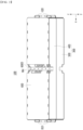
- Fig. 1 is a perspective view showing a battery module according to an embodiment of the present disclosure.
- Fig. 2 is a diagram which shows the battery module of Fig. 1 by changing the viewing angles.
- Fig. 3 is an exploded perspective view of the battery module of Fig. 1 .
- Fig. 4 is a perspective view showing a state in which the upper cover is removed from the battery module of Fig. 3 .
- a battery module 100 includes an upper battery cell stack 200U and a lower battery cell stack 200L in which a plurality of battery cells are stacked; a cooling flow path P located between the upper battery cell stack 200U and the lower battery cell stack 200L; and a module frame 300 in which the upper battery cell stack 200U and the lower battery cell stack 200L are housed.
- the cooling flow path P refers to a passage through which the refrigerant moves.
- the refrigerant is a medium for cooling, and may be cooling water as an example.
- the upper battery cell stack 200U and the lower battery cell stack 200L can be respectively formed by stacking a plurality of battery cells in one direction.
- the battery cell will be described in detail later with reference to Figs. 5 and 6 .
- the module frame 300 may include an upper frame 400 in which the upper battery cell stack 200U is housed, and a lower frame 500 in which the lower battery cell stack 200L is housed.
- a cooling flow path P may be formed between the upper frame 400 and the lower frame 500.
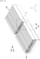
- Fig. 5 is a partial view which enlarges and shows a section "B" of Fig. 4 .
- Fig. 6 is a diagram which shows a battery cell included in the battery module of Fig. 3 .
- the battery cells 110 may be stacked in plural numbers to form an upper battery cell stack 200U and a lower battery cell stack 200L, respectively.
- the upper battery cell stack 200U is located above the lower battery cell stack 200L.
- the upper battery cell stack 200U may include a first upper battery cell stack 210U and a second upper battery cell stack 220U
- the lower battery cell stack 200L may include a first lower battery cell stack 210L and a second lower battery cell stack 220L.
- the battery cells 110 can be stacked to form a total of four battery cell stacks 210U, 220U, 210L and 220L.
- the first upper battery cell stack 210U may be located above the first lower battery cell stack 210L
- the second upper battery cell stack 220U may be located above the second lower battery cell stack 220L.
- the battery cell 110 is preferably a pouch-type battery cell, and can be formed in a rectangular sheet-like structure.
- the battery cell 110 according to the present embodiment has a structure in which two electrode leads 111 and 112 face each other and protrude from one end part 114a and the other end part 114b of the cell main body 113, respectively. That is, the battery cell 110 includes electrode leads 111 and 112 that are protruded in mutually opposite directions. More specifically, the electrode leads 111 and 112 are connected to an electrode assembly (not shown), and are protruded from the electrode assembly (not shown) to the outside of the battery cell 110.
- the battery cell 110 can be produced by joining both end parts 114a and 114b of a cell case 114 and one side part 114c connecting them in a state in which an electrode assembly (not shown) is housed in a cell case 114.
- the battery cell 110 according to the present embodiment has a total of three sealing parts 114sa, 114sb and 114sc, wherein the sealing parts 114sa, 114sb and 114sc have a structure that is sealed by a method such as heat-sealing, and the remaining other side part may be composed of a connection part 115.
- the cell case 114 may be composed of a laminated sheet including a resin layer and a metal layer.
- the connection part 115 may extend long along one edge of the battery cell 110, and a bat ear 110p may be formed at an end of the connection part 115.
- Such a battery cell 110 may be formed in plural numbers, and the plurality of battery cells 110 can be stacked so as to be electrically connected to each other, thereby forming an upper battery cell stack 200U and a lower battery cell stack 200L.
- a plurality of battery cells 110 may be stacked along the direction parallel to the y-axis.
- the electrode leads 111 and 112 may protrude in the x-axis direction and the -x-axis direction, respectively.
- the upper battery cell stack 200U and the lower battery cell stack 200L may be a large-area module in which the number of battery cells 110 is increased compared to a conventional case. Specifically, 32 to 48 battery cells 110 may be included per battery cell stack. In the case of such a large-area module, the horizontal length of the battery module becomes long.
- the horizontal length may mean a length in the direction in which the battery cells 110 are stacked, that is, in a direction parallel to the x-axis.
- a direction parallel to the protruding direction of the electrode leads 111 and 112 is referred to as a longitudinal direction d1 of the battery cell 110.
- the longitudinal direction of the battery cells 110 in Figs. 3 to 5 is a direction parallel to the x-axis.
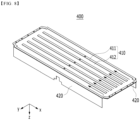
- Fig. 7 is a perspective view which shows an upper frame and a lower frame included in the battery module of Fig. 3 .
- Fig. 8 is a view showing a state in which the upper frame of Fig. 7 is reversed so that the lower surface of the bottom part can be seen.
- Fig. 9 is a cross-sectional view showing a cross section taken along the cutting line A-A' of Fig. 1 .
- Fig. 10 is a partial view which enlarges and shows a section "C" of Fig. 9 .
- the module frame 300 may include an upper frame 400 and a lower frame 500, wherein a cooling flow path P may be formed between the upper frame 400 and the lower frame 500.
- the inlet port 810 for supplying the refrigerant to the cooling flow path P and the outlet port 820 for discharging the refrigerant from the cooling flow path P are located opposite to each other, so that the refrigerant flows in one direction in the cooling flow path P.
- the longitudinal direction d1 of the battery cell 110 is in parallel with the one direction in which the refrigerant flows on the basis of the battery cell 110. More specifically, the refrigerant may flow in a straight line in the cooling flow path P. As shown in Fig. 7 , the refrigerant may flow in a straight line in a direction parallel to the x-axis in the cooling flow path P.
- the upper frame 400 may include a bottom part 410 on which the upper battery cell stack 200U is placed and a side surface parts 420 extending upward from opposite sides of the bottom part 410.
- the bottom part 410 and the side surface parts 420 may cover the lower surface and both side surfaces of the upper battery cell stack 200U, respectively.
- the lower frame 500 may include a ceiling part 510 located above the lower battery cell stack 200L and side surface parts 520 extending downward from opposite sides of the ceiling part 510.
- the upper surface and both side surfaces of the lower battery cell stack 200L may be covered by the ceiling part 510 and the side surface parts 520, respectively.
- the upper frame 400 may include an upper plate 411 that is located on the lower surface of the bottom part 410 of the upper frame 400 and an upper recessed part 412 that is recessed upward from the upper plate 411.
- Fig. 8 is a state in which the upper frame 400 is reversed so that the lower surface of the bottom part 410 can be seen, wherein the upper plate 411 is structured to protrude relatively in the -z-axis direction, and the upper recessed part 412 is structured to be relatively recessed in the z-axis direction.
- the method of forming the upper plate 411 and the upper recessed part 412 is not particularly limited.
- a partial region of the plate-shaped member can be recessed upward to form the upper plate 411 and the upper recessed part 412.
- the protruding member can be joined to the lower surface of the plate-shaped member to form the upper plate 411 and the upper recessed part 412.
- the lower frame 500 may include a lower plate 511 that is located on the upper surface of the ceiling part 510 of the lower frame 500 and a lower recessed part 512 that is recessed downward from the lower plate 511.
- the lower plate 511 is structured to protrude relatively in the z-axis direction
- the lower recessed part 512 is structured to be relatively recessed in the -z-axis direction.
- the method of forming the lower plate 511 and the lower recessed part 512 is not particularly limited.
- a partial region of the plate-shaped member can be recessed downward to form the lower plate 511 and the lower recessed part 512.
- the protruding member can be joined to the upper surface of the plate-shaped member to form the lower plate 511 and the lower recessed part 512.
- the upper plate 411 and the lower plate 511 can be joined, and the upper recessed part 412 and the lower recessed part 512 corresponding to each other can form the cooling flow path P.
- the upper plate 411 and the lower plate 511 may extend in parallel with the longitudinal direction d1 of the battery cell 110. Thereby, the refrigerant may flow in one direction through the upper recessed part 412 and the lower recessed part 512 in the cooling flow path P.
- the cooling flow path P formed in the battery module 100 according to the present embodiment extends along one direction instead of the bent path. Also, it is in parallel with the longitudinal direction d1 of the battery cell 110. Uniform cooling for each of the plurality of battery cells 110 may be possible for the upper battery cell stack 200U or the lower battery cell stack 200L. Since the temperature deviation between the battery cells 110 included in the battery module 100 leads to deterioration of battery performance, it is important to eliminate the temperature deviation. Since the battery module 100 according to the present embodiment enables uniform cooling of each battery cell 110, a temperature deviation between respective battery cells 110 can be reduced.
- the straight-line cooling flow path P can reduce pressure drop in the latter half of the cooling flow path P, compared to the paths curved in plural numbers.
- a cooling flow path having the paths curved in plural numbers particularly, a cooling flow path in which the inlet port and the outlet port of the refrigerant are located on the same side and which essentially includes a large bent path, the pressure loss of the refrigerant is large, and thus, a large-capacity refrigerant pump is required for supplying and discharging the refrigerant. Since such a large-capacity refrigerant pump occupies a large space, the space efficiency inside a device such as an automobile is deteriorated.
- the cooling flow path P according to the present embodiment is a path that extends along one direction, and pressure drop can be greatly reduced. Thereby, equivalent heat exchange performance and cooling performance can be realized even with a smaller capacity refrigerant pump. Since a refrigerant pump having a smaller capacity can be used, there is an advantage in that the space inside a device such as an automobile can be efficiently utilized.
- the upper battery cell stack 200U and the lower battery cell stack 200L have a structure stacked in two stages, and a cooling flow path P is formed therebetween. That is, the upper battery cell stack 200U and the lower battery cell stack 200L have a shape of sharing one cooling flow path P, rather than having separate cooling flow paths. As compared to forming a separate cooling path, the number of parts required for cooling can be reduced, and as the number of parts is reduced, the assembling property of the battery module can be improved. Further, since one cooling flow path P is shared, the space utilization inside the battery module 100 can be increased.
- an upper thermal resin layer may be located between the upper battery cell stack 200U and the bottom part 410 of the upper frame 400.
- a lower thermal resin layer may be located between the lower battery cell stack 200L and the ceiling part 510 of the lower frame 500.
- the upper and lower thermal resin layers can be formed by applying a thermal resin having high thermal conductivity and adhesiveness and then curing it.
- the thermal resin may include at least one of a silicone material, a urethane material, or an acrylic material. Heat generated in the upper battery cell stack 200U may be transferred to the cooling flow path P through the upper thermal resin layer, and heat generated in the lower battery cell stack 200L may be transferred to the cooling flow path P through the lower thermal resin layer.
- Fig. 11 is a perspective view which shows a lower frame according to a modified embodiment of the present disclosure.
- the lower frame 500' may include a ceiling part 510 and a side surface part 520, and may include a lower plate 511' that is located on the upper surface of the ceiling part 510 and a lower recessed part 512' that is recessed downward from the lower plate 511'.
- the cooling flow path P' formed by the lower plate 511' and the lower recessed part 512' may have a curved path while continuing in one direction. Although it is not bent at a level of about 90 degrees, a curved cooling flow path P' having bending to some degree may be formed by the lower plate 511' and the lower recessed part 512'.
- the refrigerant may flow in a curved line along one direction in the cooling flow path P'.
- the upper plate and the upper recessed part of the upper frame may also form a curved cooling flow path so as to correspond to the lower plate 511' and the lower recessed part 512'.
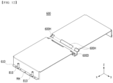
- Fig. 12 is a perspective view which shows an upper cover included in the battery module of Fig. 3 .
- Fig. 13 is a perspective view which shows a lower cover included in the battery module of Fig. 3 .
- the battery module 100 may further include an upper cover 600 for covering the opened portion of the upper frame 400 and a lower cover 700 for covering the opened portion of the lower frame 500.
- the upper cover 600 may cover the front surface and the upper surface of the first upper battery cell stack 210U, and the rear surface and the upper surface of the second upper battery cell stack 220U.
- the front surface and the upper surface of the first upper battery cell stack 210U mean a surface in the x-axis direction and a surface in the z-axis direction of the first upper battery cell stack 210U.
- the rear surface and the upper surface of the second upper battery cell stack 220U mean a surface in the - x-axis direction and a surface in the z-axis direction of the second upper battery cell stack 220U.
- the upper cover 600 and the upper frame 400 are joined to their corresponding edges, so that the upper battery cell stack 200U can be housed therein.
- the lower cover 700 may cover the front and lower surfaces of the first lower battery cell stack 210L, and the rear and lower surfaces of the second lower battery cell stack 220L.
- the front surface and the lower surface of the first lower battery cell stack 210L mean a surface in the x-axis direction and a surface in the -z-axis direction of the first lower battery cell stack 210L.
- the rear surface and the lower surface of the second lower battery cell stack 220L mean a surface in the -x-axis direction and a surface in the -z-axis direction of the second lower battery cell stack 220L.
- the lower cover 700 and the lower frame 500 are joined to their corresponding edges, so that the lower battery cell stack 200L can be housed therein.
- the upper cover 600 may include an upper recessed part 600D that is recessed downward between the first upper battery cell stack 210U and the second upper battery cell stack 220U.
- the first upper battery cell stack 210U and the second upper battery cell stack 220U may be spatially separated by the upper recessed part 600D.
- the lower cover 700 may include a lower recessed part 700D that is recessed upward between the first lower battery cell stack 210L and the second lower battery cell stack 220L.
- the first lower battery cell stack 210L and the second lower battery cell stack 220L may be spatially separated by the lower recessed part 700D.
- the first upper battery cell stack 210U and the second upper battery cell stack 220U may include an electrode terminal ET and a module connector MT, respectively.
- the electrode terminal ET and the module connector MT may be mounted on a busbar frame located on one surface of each battery cell stack.
- the electrode terminal ET may be electrically connected to any one of the electrode leads 111 and 112 (see Fig. 6 ) of the battery cell 110.
- the electrode terminal ET is exposed to the outside of the battery module 100, wherein the battery module 100 is connected to another battery module, BDU (battery disconnect unit) or the like via the electrode terminal ET, thereby capable of realizing HV (High Voltage) connection.
- the HV connection is a connection that serves as a power source for supplying power, and means a connection between battery cells or a connection between battery modules.
- the module connector MT may be electrically connected to any one of the electrode leads 111 and 112 (see Fig. 6 ) of the battery cell 110.
- the module connector MT is exposed to the outside of the battery module 100, wherein the voltage information or temperature level of the battery cell 110 is transferred to the BMS (battery management system) via the module connector (MT), thereby capable of realizing LV (low voltage) connection.
- the LV connection means a sensing connection that senses and controls the voltage and temperature information of the battery cell.
- each of the first upper battery cell stack 210U and the second upper battery cell stack 220U may include an electrode terminal ET and a module connector MT that are exposed toward the upper recessed part 600D of the upper cover 600.
- the upper cover 600 may be formed with an upper opening 600H through which the electrode terminal ET and the module connector MT of each of the first upper battery cell stack 210U and the second upper battery cell stack 220U can be exposed, wherein the upper opening 600H may be opened toward the upper recessed part 600D.
- each of the first lower battery cell stack 210L and the second lower battery cell stack 220L may include an electrode terminal and a module connector that are exposed toward the lower recessed part 700D of the lower cover 700.
- the lower cover 700 may be formed with a lower opening 700H through which electrode terminals and module connectors of the first lower battery cell stack 210L and the second lower battery cell stack 220L can be exposed, wherein the lower opening 700H may be opened toward the lower recessed part 700D.
- a high voltage (HV) connection for connecting the electrode terminals ET and a low voltage (LV) connection for connecting the module connector MT are formed in each of the upper recessed part 600D and the lower recessed part 700D. Specifically, it will be described with reference to Fig. 14 .
- Fig. 14 is a plan view which shows a battery pack according to an embodiment of the present disclosure.
- the battery pack 1000 may include a plurality of battery modules 100.
- the plurality of battery modules 100 are arranged so that the side surfaces are in contact with each other, and can be housed in the pack frame 1100.
- the electrode terminals ET exposed through the upper openings 600H of the upper recessed part 600D may be connected to each other through a connection member to form an HV connection.
- the module connectors MT exposed through the upper openings 600H of the upper recessed part 600D may be connected to each other through a connecting member to form an LV connection. As described above, it can eventually be connected to a BMS (battery management system).
- BMS battery management system
- HV connection and LV connection can be made in the upper recessed part 600D of the upper battery cell stack 200U. Meanwhile, although not specifically shown in the figure, HV connection and LV connection between the lower battery cell stacks 200L may be made similarly to the above in the lower recessed part 700D.
- an upper recessed part 600D that spatially separates the first upper battery cell stack 210U and the second upper battery cell stack 220U is formed, and HV connection and LV connection are made to the upper recessed part 600D.
- a lower recessed part 700D that spatially separates the first lower battery cell stack 210L and the second lower battery cell stack 220L is formed, and HV connection and LV connection are made to the lower recessed part 700D.
- a mounting hole MH for mounting coupling may be formed in each of the upper recessed part 600D and the lower recessed part 700D.
- the mounting hole MH of the upper recessed part 600D and the mounting hole MH of the lower recessed part 700D may be located so as to correspond to each other.
- holes may be formed in the upper plate 411 of the upper frame 400 and the lower plate 511 of the lower frame 500 so as to correspond to the mounting holes MH of the upper recessed part 600D and the lower recessed part 700D.
- the upper cover 600, the upper frame 400, the lower frame 500 and the lower cover 700 can be fixed to each other and at the same time, the battery module 100 can be fixed to the pack frame 1100.
- the fixing method through the mounting hole MH is not particularly limited, and as an example, a bolt and nut coupling can be used.
- the upper recessed part 600D and the lower recessed part 700D according to the present embodiment can not only provide a space for HV connection and LV connection, but also perform the function of fixing the mounting of the battery module 100 .
- the upper cover 600 may include a first upper protrusion part 610 located on one side and a second upper protrusion part 620 located on the other side opposite to the one side.
- An inlet port 810 may be located in the first upper protrusion part 610, and an outlet port 820 may be located in the second upper protrusion part 620. As described above, the inlet port 810 for supplying the refrigerant to the cooling flow path P and the outlet port 820 for discharging the refrigerant from the cooling flow path P may be located opposite to each other. The refrigerant inflowed through the inlet port 810 may flow along the cooling flow path P in one direction and then be discharged through the outlet port 820.
- the lower cover 700 may include a first lower protrusion part 710 located so as to correspond to the first upper protrusion part 610 and a second lower protrusion part 720 located so as to correspond to the second upper protrusion part 620.
- a mounting hole MH for mounting coupling may be formed in each of the first upper protrusion part 610 and the first lower protrusion part 710.
- the mounting hole MH of the first upper protrusion part 610 and the mounting hole MH of the first lower protrusion part 710 may be located so as to correspond to each other.
- a mounting hole for mounting coupling may be formed in each of the second upper protrusion part 620 and the second lower protrusion part 720.
- the mounting hole MH of the second upper protrusion part 620 and the mounting hole MH of the second lower protrusion part 720 may be located so as to correspond to each other.
- the first upper protrusion part 610 and the first lower protrusion part 710 may be coupled to each other through the mounting hole MH.
- the battery module 100 may be fixed to the pack frame 1100 through the mounting holes MH of the first upper protrusion part 610 and the first lower protrusion part 710.
- the second upper protrusion part 620 and the second lower protrusion part 720 may be coupled to each other through the mounting hole MH.
- the battery module 100 may be fixed to the pack frame 1100 through the mounting holes MH of the second upper protrusion part 620 and the second lower protrusion part 720.
- the first upper protrusion part 610 provided with the inlet port 810 is mount-coupled to the first lower protrusion part 710, it is possible to reduce the possibility of leakage of the refrigerant through the gap between the first upper protrusion part 610 and the first lower protrusion part 710. That is, the pressing force of the mounting coupling can be used as a sealing force for preventing leakage in the process of inflowing the refrigerant.
- the second upper protrusion part 620 provided with the outlet port 820 is mount-coupled to the second lower protrusion part 720, it is possible to reduce the possibility of leakage of the refrigerant through the gap between the second upper protrusion part 620 and the second lower protrusion part 720. That is, the pressing force of the mounting coupling can be used as a sealing force for preventing leakage in the discharge process of the refrigerant.
- the one or more battery modules according to embodiments of the present disclosure described above can be mounted together with various control and protection systems such as a BMS(battery management system), a BDU(battery disconnect unit), and a cooling system to form a battery pack.
- BMS battery management system
- BDU battery disconnect unit
- the battery module or the battery pack can be applied to various devices.
- vehicle means such as an electric bike, an electric vehicle, and a hybrid electric vehicle, and may be applied to various devices capable of using a secondary battery, without being limited thereto.
Abstract
A battery module according to an embodiment of the present disclosure includes an upper battery cell stack and a lower battery cell stack in which a plurality of battery cells are stacked; a cooling flow path located between the upper battery cell stack and the lower battery cell stack; and a module frame in which the upper battery cell stack and the lower battery cell stack are housed. An inlet port for supplying a refrigerant to the cooling flow path and an outlet port for discharging the refrigerant from the cooling flow path are located opposite to each other, so that the refrigerant flows in one direction in the cooling flow path. A longitudinal direction of the battery cell is in parallel with the one direction in which the refrigerant flows.
Description
- This application claims the benefit of
Korean Patent Application No. 10-2021-0036923 filed on March 22, 2021 - The present disclosure relates to a battery module and a battery pack including the same, and more particularly to a battery module having improved space utilization and cooling efficiency and a battery pack including the same.
- In modern society, as portable devices such as a mobile phone, a notebook computer, a camcorder and a digital camera has been daily used, the development of technologies in the fields related to mobile devices as described above has been activated. In addition, chargeable/dischargeable secondary batteries are used as a power source for an electric vehicle (EV), a hybrid electric vehicle (HEV), a plug-in hybrid electric vehicle (P-HEV) and the like, in an attempt to solve air pollution and the like caused by existing gasoline vehicles using fossil fuel. Therefore, the demand for development of the secondary battery is growing.
- Currently commercialized secondary batteries include a nickel cadmium battery, a nickel hydrogen battery, a nickel zinc battery, and a lithium secondary battery. Among them, the lithium secondary battery has come into the spotlight because they have advantages, for example, hardly exhibiting memory effects compared to nickel-based secondary batteries and thus being freely charged and discharged, and having very low self-discharge rate and high energy density.
- Such lithium secondary battery mainly uses a lithium-based oxide and a carbonaceous material as a cathode active material and an anode active material, respectively. The lithium secondary battery includes an electrode assembly in which a cathode plate and an anode plate, each being coated with the cathode active material and the anode active material, are arranged with a separator being interposed between them, and a battery case which seals and houses the electrode assembly together with an electrolytic solution.
- Generally, the lithium secondary battery may be classified based on the shape of the exterior material into a can-type secondary battery in which the electrode assembly is mounted in a metal can, and a pouch-type secondary battery in which the electrode assembly is mounted in a pouch of an aluminum laminate sheet.
- In the case of a secondary battery used for small-sized devices, two to three battery cells are arranged, but in the case of a secondary battery used for a middle- or large-sized device such as an automobile, a battery module in which a large number of battery cells are electrically connected is used. In such a battery module, a large number of battery cells are connected to each other in series or parallel to form a cell assembly, thereby improving capacity and output. One or more battery modules can be mounted together with various control and protection systems such as a BDU(battery disconnect unit), a BMS (battery management system) and a cooling system to form a battery pack.
- It is an object of the present disclosure to provide a battery module having improved space utilization and cooling efficiency, and a battery pack including the same.
- However, the problem to be solved by embodiments of the present disclosure is not limited to the above-described problems, and can be variously expanded within the scope of the technical idea included in the present disclosure.
- A battery module according to an embodiment of the present disclosure includes an upper battery cell stack and a lower battery cell stack in which a plurality of battery cells are stacked; a cooling flow path located between the upper battery cell stack and the lower battery cell stack; and a module frame in which the upper battery cell stack and the lower battery cell stack are housed. An inlet port for supplying a refrigerant to the cooling flow path and an outlet port for discharging the refrigerant from the cooling flow path are located opposite to each other, so that the refrigerant flows in one direction in the cooling flow path. A longitudinal direction of the battery cell is in parallel with the one direction in which the refrigerant flows.
- The refrigerant may flow in a straight line in the cooling flow path.
- In the cooling flow path, the refrigerant may flow in a curved line along the one direction.
- The module frame may include an upper frame in which the upper battery cell stack is housed and a lower frame in which the lower battery cell stack is housed, and the cooling flow path may be formed between the upper frame and the lower frame.
- The upper frame may include an upper plate that is located on the lower surface of the bottom part of the upper frame, and an upper recessed part that is recessed upward from the upper plate. The lower frame may include a lower plate that is located on the upper surface of the ceiling part of the lower frame, and a lower recessed part that is recessed downward from the lower plate. The upper plate and the lower plate are joined so that the upper recessed part and the lower recessed part can form the cooling flow path.
- The battery module may further include an upper cover that covers the opened portion of the upper frame and a lower cover that covers the opened portion of the lower frame.
- The upper battery cell stack may include a first upper battery cell stack and a second upper battery cell stack. The lower battery cell stack may include a first lower battery cell stack and a second lower battery cell stack.
- The upper cover may include an upper recessed part that is recessed downward between the first upper battery cell stack and the second upper battery cell stack. The lower cover may include a lower recessed part that is recessed upward recessed between the first lower battery cell stack and the second lower battery cell stack.
- Each of the first upper battery cell stack and the second upper battery cell stack may include an electrode terminal and a module connector exposed toward the upper recessed part. Each of the first lower battery cell stack and the second lower battery cell stack may include an electrode terminal and a module connector exposed toward the lower recessed part. A HV (high voltage) connection for connecting the electrode terminals and a LV (low voltage) connection for connecting the module connector may be formed in each of the upper recessed part and the lower recessed part.
- The first upper battery cell stack and the second upper battery cell stack may be spatially separated by the upper recessed part. The first lower battery cell stack and the second lower battery cell stack may be spatially separated by the lower recessed part.
- A mounting hole for mounting coupling may be formed in each of the upper recessed part and the lower recessed part. The mounting hole of the upper recessed part and the mounting hole of the lower recessed part may be located so as to correspond to each other.
- The upper cover may include a first upper protrusion part located on one side and a second upper protrusion part located on the other side opposite to the one side. The inlet port may be located in the first upper protrusion part, and the outlet port may be located in the second upper protrusion part.
- The lower cover may include a first lower protrusion part located so as to correspond to the first upper protrusion part, and a second lower protrusion part located so as to correspond to the second upper protrusion part.
- A mounting hole for mounting coupling may be formed in each of the first upper protrusion part and the first lower protrusion part. A mounting hole for mounting coupling may be formed in each of the second upper protrusion part and the second lower protrusion part.
- According to an embodiment of the present disclosure, the battery cell stack is arranged in a two-stage structure and the cooling flow path is arranged so as to share between them, thereby capable of improving space utilization and cooling efficiency. In addition, the cooling flow is configured so as to flow in one direction, thereby capable of reducing the pressure drop of the refrigerant.
- The effects of the present disclosure are not limited to the effects mentioned above and additional other effects not described above will be clearly understood from the description of the appended claims by those skilled in the art.
-
-
Fig. 1 is a perspective view showing a battery module according to an embodiment of the present disclosure; -
Fig. 2 is a diagram which shows the battery module ofFig. 1 by changing the viewing angles; -
Fig. 3 is an exploded perspective view of the battery module ofFig. 1 ; -
Fig. 4 is a perspective view showing a state in which the upper cover is removed from the battery module ofFig. 3 ; -
Fig. 5 is a partial view which enlarges and shows a section "B" ofFig. 4 ; -
Fig. 6 is a diagram which shows a battery cell included in the battery module ofFig. 3 ; -
Fig. 7 is a perspective view which shows an upper frame and a lower frame included in the battery module ofFig. 3 ; -
Fig. 8 is a view showing a state in which the upper frame ofFig. 7 is reversed so that the lower surface of the bottom part can be seen; -
Fig. 9 is a cross-sectional view showing a cross section taken along the cutting line A-A' ofFig. 1 ; -
Fig. 10 is a partial view which enlarges and shows a section "C" ofFig. 9 ; -
Fig. 11 is a perspective view which shows a lower frame according to a modified embodiment of the present disclosure; -
Fig. 12 is a perspective view which shows an upper cover included in the battery module ofFig. 3 ; -
Fig. 13 is a perspective view which shows a lower cover included in the battery module ofFig. 3 ; and -
Fig. 14 is a plan view which shows a battery pack according to an embodiment of the present disclosure. - Hereinafter, various embodiments of the present disclosure will be described in detail with reference to the accompanying drawings so that those skilled in the art can easily carry out them. The present disclosure may be modified in various different ways, and is not limited to the embodiments set forth herein.
- Portions that are irrelevant to the description will be omitted to clearly describe the present disclosure, and like reference numerals designate like elements throughout the description.
- Further, in the drawings, the size and thickness of each element are arbitrarily illustrated for convenience of description, and the present disclosure is not necessarily limited to those illustrated in the drawings. In the drawings, the thickness of layers, regions, etc. are exaggerated for clarity. In the drawings, for convenience of description, the thicknesses of some layers and regions are exaggerated.
- In addition, it will be understood that when an element such as a layer, film, region, or plate is referred to as being "on" or "above" another element, it can be directly on the other element or intervening elements may also be present. In contrast, when an element is referred to as being "directly on" another element, it means that other intervening elements are not present. Further, the word "on" or "above" means disposed on or below a reference portion, and does not necessarily mean being disposed on the upper end of the reference portion toward the opposite direction of gravity.
- Further, throughout the description, when a portion is referred to as "including" or "comprising" a certain component, it means that the portion can further include other components, without excluding the other components, unless otherwise stated.
- Further, throughout the description, when referred to as "planar", it means when a target portion is viewed from the upper side, and when referred to as "cross-sectional", it means when a target portion is viewed from the side of a cross section cut vertically.
-
Fig. 1 is a perspective view showing a battery module according to an embodiment of the present disclosure.Fig. 2 is a diagram which shows the battery module ofFig. 1 by changing the viewing angles.Fig. 3 is an exploded perspective view of the battery module ofFig. 1 .Fig. 4 is a perspective view showing a state in which the upper cover is removed from the battery module ofFig. 3 . - Referring to
Figs. 1 to 4 , abattery module 100 according to one embodiment of the present disclosure includes an upperbattery cell stack 200U and a lowerbattery cell stack 200L in which a plurality of battery cells are stacked; a cooling flow path P located between the upperbattery cell stack 200U and the lowerbattery cell stack 200L; and amodule frame 300 in which the upperbattery cell stack 200U and the lowerbattery cell stack 200L are housed. The cooling flow path P refers to a passage through which the refrigerant moves. The refrigerant is a medium for cooling, and may be cooling water as an example. - The upper
battery cell stack 200U and the lowerbattery cell stack 200L can be respectively formed by stacking a plurality of battery cells in one direction. The battery cell will be described in detail later with reference toFigs. 5 and6 . - The
module frame 300 according to the present embodiment may include anupper frame 400 in which the upperbattery cell stack 200U is housed, and alower frame 500 in which the lowerbattery cell stack 200L is housed. A cooling flow path P may be formed between theupper frame 400 and thelower frame 500. -
Fig. 5 is a partial view which enlarges and shows a section "B" ofFig. 4 .Fig. 6 is a diagram which shows a battery cell included in the battery module ofFig. 3 . - Referring to
Figs. 3 ,5 and6 , thebattery cells 110 according to the present embodiment may be stacked in plural numbers to form an upperbattery cell stack 200U and a lowerbattery cell stack 200L, respectively. The upperbattery cell stack 200U is located above the lowerbattery cell stack 200L. - Further, the upper
battery cell stack 200U may include a first upperbattery cell stack 210U and a second upperbattery cell stack 220U, and the lowerbattery cell stack 200L may include a first lowerbattery cell stack 210L and a second lowerbattery cell stack 220L. Thebattery cells 110 can be stacked to form a total of four battery cell stacks 210U, 220U, 210L and 220L. The first upperbattery cell stack 210U may be located above the first lowerbattery cell stack 210L, and the second upperbattery cell stack 220U may be located above the second lowerbattery cell stack 220L. - The
battery cell 110 is preferably a pouch-type battery cell, and can be formed in a rectangular sheet-like structure. For example, thebattery cell 110 according to the present embodiment has a structure in which two electrode leads 111 and 112 face each other and protrude from oneend part 114a and theother end part 114b of the cellmain body 113, respectively. That is, thebattery cell 110 includes electrode leads 111 and 112 that are protruded in mutually opposite directions. More specifically, the electrode leads 111 and 112 are connected to an electrode assembly (not shown), and are protruded from the electrode assembly (not shown) to the outside of thebattery cell 110. - Meanwhile, the
battery cell 110 can be produced by joining bothend parts cell case 114 and oneside part 114c connecting them in a state in which an electrode assembly (not shown) is housed in acell case 114. In other words, thebattery cell 110 according to the present embodiment has a total of three sealing parts 114sa, 114sb and 114sc, wherein the sealing parts 114sa, 114sb and 114sc have a structure that is sealed by a method such as heat-sealing, and the remaining other side part may be composed of aconnection part 115. Thecell case 114 may be composed of a laminated sheet including a resin layer and a metal layer. Further, theconnection part 115 may extend long along one edge of thebattery cell 110, and abat ear 110p may be formed at an end of theconnection part 115. - Such a
battery cell 110 may be formed in plural numbers, and the plurality ofbattery cells 110 can be stacked so as to be electrically connected to each other, thereby forming an upperbattery cell stack 200U and a lowerbattery cell stack 200L. - Particularly, as shown in
Fig. 5 , a plurality ofbattery cells 110 may be stacked along the direction parallel to the y-axis. Thereby, the electrode leads 111 and 112 may protrude in the x-axis direction and the -x-axis direction, respectively. - The upper
battery cell stack 200U and the lowerbattery cell stack 200L according to the present embodiment may be a large-area module in which the number ofbattery cells 110 is increased compared to a conventional case. Specifically, 32 to 48battery cells 110 may be included per battery cell stack. In the case of such a large-area module, the horizontal length of the battery module becomes long. Here, the horizontal length may mean a length in the direction in which thebattery cells 110 are stacked, that is, in a direction parallel to the x-axis. - Meanwhile, referring to
Fig. 6 again, in the electrode leads 111 and 112 protruding in mutually opposite directions, a direction parallel to the protruding direction of the electrode leads 111 and 112 is referred to as a longitudinal direction d1 of thebattery cell 110. Considering the stacking direction of thebattery cells 110, the longitudinal direction of thebattery cells 110 inFigs. 3 to 5 is a direction parallel to the x-axis. - Next, the cooling flow path and the module frame according to the present embodiment will be described in detail with reference to
Figs. 7 to 10 . -
Fig. 7 is a perspective view which shows an upper frame and a lower frame included in the battery module ofFig. 3 .Fig. 8 is a view showing a state in which the upper frame ofFig. 7 is reversed so that the lower surface of the bottom part can be seen.Fig. 9 is a cross-sectional view showing a cross section taken along the cutting line A-A' ofFig. 1 .Fig. 10 is a partial view which enlarges and shows a section "C" ofFig. 9 . - Referring to
Figs. 3 and7 to 10 , themodule frame 300 according to the present embodiment may include anupper frame 400 and alower frame 500, wherein a cooling flow path P may be formed between theupper frame 400 and thelower frame 500. Theinlet port 810 for supplying the refrigerant to the cooling flow path P and theoutlet port 820 for discharging the refrigerant from the cooling flow path P are located opposite to each other, so that the refrigerant flows in one direction in the cooling flow path P. In addition, the longitudinal direction d1 of thebattery cell 110 is in parallel with the one direction in which the refrigerant flows on the basis of thebattery cell 110. More specifically, the refrigerant may flow in a straight line in the cooling flow path P. As shown inFig. 7 , the refrigerant may flow in a straight line in a direction parallel to the x-axis in the cooling flow path P. - The
upper frame 400 according to the present embodiment may include abottom part 410 on which the upperbattery cell stack 200U is placed and aside surface parts 420 extending upward from opposite sides of thebottom part 410. Thebottom part 410 and theside surface parts 420 may cover the lower surface and both side surfaces of the upperbattery cell stack 200U, respectively. - The
lower frame 500 according to the present embodiment may include aceiling part 510 located above the lowerbattery cell stack 200L and side surfaceparts 520 extending downward from opposite sides of theceiling part 510. The upper surface and both side surfaces of the lowerbattery cell stack 200L may be covered by theceiling part 510 and theside surface parts 520, respectively. - Referring to
Figs. 7 and8 , theupper frame 400 may include anupper plate 411 that is located on the lower surface of thebottom part 410 of theupper frame 400 and an upper recessedpart 412 that is recessed upward from theupper plate 411. As described above,Fig. 8 is a state in which theupper frame 400 is reversed so that the lower surface of thebottom part 410 can be seen, wherein theupper plate 411 is structured to protrude relatively in the -z-axis direction, and the upper recessedpart 412 is structured to be relatively recessed in the z-axis direction. The method of forming theupper plate 411 and the upper recessedpart 412 is not particularly limited. For example, a partial region of the plate-shaped member can be recessed upward to form theupper plate 411 and the upper recessedpart 412. As another example, the protruding member can be joined to the lower surface of the plate-shaped member to form theupper plate 411 and the upper recessedpart 412. - The
lower frame 500 may include alower plate 511 that is located on the upper surface of theceiling part 510 of thelower frame 500 and a lower recessedpart 512 that is recessed downward from thelower plate 511. As shown inFig. 7 , thelower plate 511 is structured to protrude relatively in the z-axis direction, and the lower recessedpart 512 is structured to be relatively recessed in the -z-axis direction. The method of forming thelower plate 511 and the lower recessedpart 512 is not particularly limited. For example, a partial region of the plate-shaped member can be recessed downward to form thelower plate 511 and the lower recessedpart 512. As another example, the protruding member can be joined to the upper surface of the plate-shaped member to form thelower plate 511 and the lower recessedpart 512. - When the
bottom part 410 of theupper frame 400 is placed on theceiling part 510 of thelower frame 500, theupper plate 411 and thelower plate 511 can be joined, and the upper recessedpart 412 and the lower recessedpart 512 corresponding to each other can form the cooling flow path P. - The
upper plate 411 and thelower plate 511 may extend in parallel with the longitudinal direction d1 of thebattery cell 110. Thereby, the refrigerant may flow in one direction through the upper recessedpart 412 and the lower recessedpart 512 in the cooling flow path P. - The cooling flow path P formed in the
battery module 100 according to the present embodiment extends along one direction instead of the bent path. Also, it is in parallel with the longitudinal direction d1 of thebattery cell 110. Uniform cooling for each of the plurality ofbattery cells 110 may be possible for the upperbattery cell stack 200U or the lowerbattery cell stack 200L. Since the temperature deviation between thebattery cells 110 included in thebattery module 100 leads to deterioration of battery performance, it is important to eliminate the temperature deviation. Since thebattery module 100 according to the present embodiment enables uniform cooling of eachbattery cell 110, a temperature deviation betweenrespective battery cells 110 can be reduced. - Further, in accordance with the present embodiment, the straight-line cooling flow path P can reduce pressure drop in the latter half of the cooling flow path P, compared to the paths curved in plural numbers. In the case of a cooling flow path having the paths curved in plural numbers, particularly, a cooling flow path in which the inlet port and the outlet port of the refrigerant are located on the same side and which essentially includes a large bent path, the pressure loss of the refrigerant is large, and thus, a large-capacity refrigerant pump is required for supplying and discharging the refrigerant. Since such a large-capacity refrigerant pump occupies a large space, the space efficiency inside a device such as an automobile is deteriorated. On the other hand, the cooling flow path P according to the present embodiment is a path that extends along one direction, and pressure drop can be greatly reduced. Thereby, equivalent heat exchange performance and cooling performance can be realized even with a smaller capacity refrigerant pump. Since a refrigerant pump having a smaller capacity can be used, there is an advantage in that the space inside a device such as an automobile can be efficiently utilized.
- Meanwhile, as described above, the upper
battery cell stack 200U and the lowerbattery cell stack 200L have a structure stacked in two stages, and a cooling flow path P is formed therebetween. That is, the upperbattery cell stack 200U and the lowerbattery cell stack 200L have a shape of sharing one cooling flow path P, rather than having separate cooling flow paths. As compared to forming a separate cooling path, the number of parts required for cooling can be reduced, and as the number of parts is reduced, the assembling property of the battery module can be improved. Further, since one cooling flow path P is shared, the space utilization inside thebattery module 100 can be increased. - Meanwhile, an upper thermal resin layer may be located between the upper
battery cell stack 200U and thebottom part 410 of theupper frame 400. Also, a lower thermal resin layer may be located between the lowerbattery cell stack 200L and theceiling part 510 of thelower frame 500. The upper and lower thermal resin layers can be formed by applying a thermal resin having high thermal conductivity and adhesiveness and then curing it. In one example, the thermal resin may include at least one of a silicone material, a urethane material, or an acrylic material. Heat generated in the upperbattery cell stack 200U may be transferred to the cooling flow path P through the upper thermal resin layer, and heat generated in the lowerbattery cell stack 200L may be transferred to the cooling flow path P through the lower thermal resin layer. -
Fig. 11 is a perspective view which shows a lower frame according to a modified embodiment of the present disclosure. - Referring to
Fig. 11 , the lower frame 500' according to a modified embodiment of the present disclosure may include aceiling part 510 and aside surface part 520, and may include a lower plate 511' that is located on the upper surface of theceiling part 510 and a lower recessed part 512' that is recessed downward from the lower plate 511'. The cooling flow path P' formed by the lower plate 511' and the lower recessed part 512' may have a curved path while continuing in one direction. Although it is not bent at a level of about 90 degrees, a curved cooling flow path P' having bending to some degree may be formed by the lower plate 511' and the lower recessed part 512'. Thereby, the refrigerant may flow in a curved line along one direction in the cooling flow path P'. Meanwhile, although not specifically shown in the figure, the upper plate and the upper recessed part of the upper frame may also form a curved cooling flow path so as to correspond to the lower plate 511' and the lower recessed part 512'. - Next, the upper cover, the lower cover, and the HV and LV connection structures according to the present embodiment will be described in detail with reference to
Figs. 12 and13 . -
Fig. 12 is a perspective view which shows an upper cover included in the battery module ofFig. 3 .Fig. 13 is a perspective view which shows a lower cover included in the battery module ofFig. 3 . - Referring to
Figs. 3 ,5 ,12 and13 , thebattery module 100 according to the present embodiment may further include anupper cover 600 for covering the opened portion of theupper frame 400 and alower cover 700 for covering the opened portion of thelower frame 500. - The
upper cover 600 may cover the front surface and the upper surface of the first upperbattery cell stack 210U, and the rear surface and the upper surface of the second upperbattery cell stack 220U. Here, the front surface and the upper surface of the first upperbattery cell stack 210U mean a surface in the x-axis direction and a surface in the z-axis direction of the first upperbattery cell stack 210U. The rear surface and the upper surface of the second upperbattery cell stack 220U mean a surface in the - x-axis direction and a surface in the z-axis direction of the second upperbattery cell stack 220U. - The
upper cover 600 and theupper frame 400 are joined to their corresponding edges, so that the upperbattery cell stack 200U can be housed therein. - The
lower cover 700 may cover the front and lower surfaces of the first lowerbattery cell stack 210L, and the rear and lower surfaces of the second lowerbattery cell stack 220L. Here, the front surface and the lower surface of the first lowerbattery cell stack 210L mean a surface in the x-axis direction and a surface in the -z-axis direction of the first lowerbattery cell stack 210L. The rear surface and the lower surface of the second lowerbattery cell stack 220L mean a surface in the -x-axis direction and a surface in the -z-axis direction of the second lowerbattery cell stack 220L. - The
lower cover 700 and thelower frame 500 are joined to their corresponding edges, so that the lowerbattery cell stack 200L can be housed therein. - The
upper cover 600 may include an upper recessedpart 600D that is recessed downward between the first upperbattery cell stack 210U and the second upperbattery cell stack 220U. The first upperbattery cell stack 210U and the second upperbattery cell stack 220U may be spatially separated by the upper recessedpart 600D. - The
lower cover 700 may include a lower recessedpart 700D that is recessed upward between the first lowerbattery cell stack 210L and the second lowerbattery cell stack 220L. The first lowerbattery cell stack 210L and the second lowerbattery cell stack 220L may be spatially separated by the lower recessedpart 700D. - Referring to
Fig. 5 , the first upperbattery cell stack 210U and the second upperbattery cell stack 220U may include an electrode terminal ET and a module connector MT, respectively. The electrode terminal ET and the module connector MT may be mounted on a busbar frame located on one surface of each battery cell stack. - The electrode terminal ET may be electrically connected to any one of the electrode leads 111 and 112 (see
Fig. 6 ) of thebattery cell 110. The electrode terminal ET is exposed to the outside of thebattery module 100, wherein thebattery module 100 is connected to another battery module, BDU (battery disconnect unit) or the like via the electrode terminal ET, thereby capable of realizing HV (High Voltage) connection. Here, the HV connection is a connection that serves as a power source for supplying power, and means a connection between battery cells or a connection between battery modules. - The module connector MT may be electrically connected to any one of the electrode leads 111 and 112 (see
Fig. 6 ) of thebattery cell 110. The module connector MT is exposed to the outside of thebattery module 100, wherein the voltage information or temperature level of thebattery cell 110 is transferred to the BMS (battery management system) via the module connector (MT), thereby capable of realizing LV (low voltage) connection. Here, the LV connection means a sensing connection that senses and controls the voltage and temperature information of the battery cell. - Referring to
Figs. 1 and5 together, each of the first upperbattery cell stack 210U and the second upperbattery cell stack 220U may include an electrode terminal ET and a module connector MT that are exposed toward the upper recessedpart 600D of theupper cover 600. In other words, theupper cover 600 may be formed with anupper opening 600H through which the electrode terminal ET and the module connector MT of each of the first upperbattery cell stack 210U and the second upperbattery cell stack 220U can be exposed, wherein theupper opening 600H may be opened toward the upper recessedpart 600D. - Although specifically not shown in the figure, each of the first lower
battery cell stack 210L and the second lowerbattery cell stack 220L may include an electrode terminal and a module connector that are exposed toward the lower recessedpart 700D of thelower cover 700. In other words, thelower cover 700 may be formed with alower opening 700H through which electrode terminals and module connectors of the first lowerbattery cell stack 210L and the second lowerbattery cell stack 220L can be exposed, wherein thelower opening 700H may be opened toward the lower recessedpart 700D. - At this time, a high voltage (HV) connection for connecting the electrode terminals ET and a low voltage (LV) connection for connecting the module connector MT are formed in each of the upper recessed
part 600D and the lower recessedpart 700D. Specifically, it will be described with reference toFig. 14 . -
Fig. 14 is a plan view which shows a battery pack according to an embodiment of the present disclosure. - Referring to
Fig. 14 together withFigs. 1 ,5 and12 , thebattery pack 1000 according to an embodiment of the present disclosure may include a plurality ofbattery modules 100. The plurality ofbattery modules 100 are arranged so that the side surfaces are in contact with each other, and can be housed in thepack frame 1100. The electrode terminals ET exposed through theupper openings 600H of the upper recessedpart 600D may be connected to each other through a connection member to form an HV connection. Further, the module connectors MT exposed through theupper openings 600H of the upper recessedpart 600D may be connected to each other through a connecting member to form an LV connection. As described above, it can eventually be connected to a BMS (battery management system). HV connection and LV connection can be made in the upper recessedpart 600D of the upperbattery cell stack 200U. Meanwhile, although not specifically shown in the figure, HV connection and LV connection between the lower battery cell stacks 200L may be made similarly to the above in the lower recessedpart 700D. - That is, according to the present embodiment, it has been configured such that an upper recessed
part 600D that spatially separates the first upperbattery cell stack 210U and the second upperbattery cell stack 220U is formed, and HV connection and LV connection are made to the upper recessedpart 600D. Similarly, it has been configured such that a lower recessedpart 700D that spatially separates the first lowerbattery cell stack 210L and the second lowerbattery cell stack 220L is formed, and HV connection and LV connection are made to the lower recessedpart 700D. By providing a separate space for HV connection and LV connection, as in the upper recessedpart 600D and the lower recessedpart 700D, the connection form of HV connection and LV connection can be simplified, and space can be used efficiently. - Meanwhile, referring to
Figs. 2 ,7 ,8 ,12 ,13 and14 together, a mounting hole MH for mounting coupling may be formed in each of the upper recessedpart 600D and the lower recessedpart 700D. The mounting hole MH of the upper recessedpart 600D and the mounting hole MH of the lower recessedpart 700D may be located so as to correspond to each other. - Further, holes may be formed in the
upper plate 411 of theupper frame 400 and thelower plate 511 of thelower frame 500 so as to correspond to the mounting holes MH of the upper recessedpart 600D and the lower recessedpart 700D. - Using the mounting hole MH of the upper recessed
part 600D and the mounting hole MH of the lower recessedpart 700D, theupper cover 600, theupper frame 400, thelower frame 500 and thelower cover 700 can be fixed to each other and at the same time, thebattery module 100 can be fixed to thepack frame 1100. The fixing method through the mounting hole MH is not particularly limited, and as an example, a bolt and nut coupling can be used. The upper recessedpart 600D and the lower recessedpart 700D according to the present embodiment can not only provide a space for HV connection and LV connection, but also perform the function of fixing the mounting of thebattery module 100 . - Next, the first upper protrusion part and the second upper protrusion part according to an embodiment of the present disclosure will be described in detail.
- Referring to
Figs. 1 ,10 to 13 , theupper cover 600 according to the present embodiment may include a firstupper protrusion part 610 located on one side and a secondupper protrusion part 620 located on the other side opposite to the one side. - An
inlet port 810 may be located in the firstupper protrusion part 610, and anoutlet port 820 may be located in the secondupper protrusion part 620. As described above, theinlet port 810 for supplying the refrigerant to the cooling flow path P and theoutlet port 820 for discharging the refrigerant from the cooling flow path P may be located opposite to each other. The refrigerant inflowed through theinlet port 810 may flow along the cooling flow path P in one direction and then be discharged through theoutlet port 820. - The
lower cover 700 according to the present embodiment may include a firstlower protrusion part 710 located so as to correspond to the firstupper protrusion part 610 and a secondlower protrusion part 720 located so as to correspond to the secondupper protrusion part 620. - A mounting hole MH for mounting coupling may be formed in each of the first
upper protrusion part 610 and the firstlower protrusion part 710. The mounting hole MH of the firstupper protrusion part 610 and the mounting hole MH of the firstlower protrusion part 710 may be located so as to correspond to each other. - Further, a mounting hole for mounting coupling may be formed in each of the second
upper protrusion part 620 and the secondlower protrusion part 720. The mounting hole MH of the secondupper protrusion part 620 and the mounting hole MH of the secondlower protrusion part 720 may be located so as to correspond to each other. - That is, the first
upper protrusion part 610 and the firstlower protrusion part 710 may be coupled to each other through the mounting hole MH. In addition, thebattery module 100 may be fixed to thepack frame 1100 through the mounting holes MH of the firstupper protrusion part 610 and the firstlower protrusion part 710. Similarly, the secondupper protrusion part 620 and the secondlower protrusion part 720 may be coupled to each other through the mounting hole MH. Also, thebattery module 100 may be fixed to thepack frame 1100 through the mounting holes MH of the secondupper protrusion part 620 and the secondlower protrusion part 720. - Because the first
upper protrusion part 610 provided with theinlet port 810 is mount-coupled to the firstlower protrusion part 710, it is possible to reduce the possibility of leakage of the refrigerant through the gap between the firstupper protrusion part 610 and the firstlower protrusion part 710. That is, the pressing force of the mounting coupling can be used as a sealing force for preventing leakage in the process of inflowing the refrigerant. - In addition, because the second
upper protrusion part 620 provided with theoutlet port 820 is mount-coupled to the secondlower protrusion part 720, it is possible to reduce the possibility of leakage of the refrigerant through the gap between the secondupper protrusion part 620 and the secondlower protrusion part 720. That is, the pressing force of the mounting coupling can be used as a sealing force for preventing leakage in the discharge process of the refrigerant. - The terms representing directions such as the front side, the rear side, the left side, the right side, the upper side, and the lower side have been used in embodiments of the present disclosure, but the terms used are provided simply for convenience of description and may become different according to the position of an object, the position of an observer, or the like.
- The one or more battery modules according to embodiments of the present disclosure described above can be mounted together with various control and protection systems such as a BMS(battery management system), a BDU(battery disconnect unit), and a cooling system to form a battery pack.
- The battery module or the battery pack can be applied to various devices. For example, it can be applied to vehicle means such as an electric bike, an electric vehicle, and a hybrid electric vehicle, and may be applied to various devices capable of using a secondary battery, without being limited thereto.
- The present disclosure has been described in detail with reference to exemplary embodiments thereof, but the scope of the present disclosure is not limited thereto and modifications and improvements made by those skilled in the part by using the basic concept of the present disclosure, which are defined in the following claims, also belong to the scope of the present disclosure.
-
- 100: battery module
- 200U: upper battery cell stack
- 200L: lower battery cell stack
- 300: module frame
- P: cooling flow path
Claims (15)
- A battery module comprising:an upper battery cell stack and a lower battery cell stack in which a plurality of battery cells are stacked;a cooling flow path located between the upper battery cell stack and the lower battery cell stack; anda module frame in which the upper battery cell stack and the lower battery cell stack are housed,wherein an inlet port for supplying a refrigerant to the cooling flow path and an outlet port for discharging the refrigerant from the cooling flow path are located opposite to each other, so that the refrigerant flows in one direction in the cooling flow path, andwherein a longitudinal direction of the battery cell is in parallel with the one direction in which the refrigerant flows.
- The battery module according to claim 1 wherein:
the refrigerant flows in a straight line in the cooling flow path. - The battery module according to claim 1 wherein:
in the cooling flow path, the refrigerant flows in a curved line along the one direction. - The battery module according to claim 1 wherein:the module frame comprises an upper frame in which the upper battery cell stack is housed and a lower frame in which the lower battery cell stack is housed, andthe cooling flow path is formed between the upper frame and the lower frame.
- The battery module according to claim 4 wherein:the upper frame comprises an upper plate that is located on the lower surface of the bottom part of the upper frame, and an upper recessed part that is recessed upward from the upper plate,the lower frame comprises a lower plate that is located on the upper surface of the ceiling part of the lower frame, and a lower recessed part that is recessed downward from the lower plate, andthe upper plate and the lower plate are joined so that the upper recessed part and the lower recessed part form the cooling flow path.
- The battery module according to claim 4, further comprising:
an upper cover that covers the opened portion of the upper frame and a lower cover that covers the opened portion of the lower frame. - The battery module according to claim 6 wherein:the upper battery cell stack comprises a first upper battery cell stack and a second upper battery cell stack, andthe lower battery cell stack comprises a first lower battery cell stack and a second lower battery cell stack.
- The battery module according to claim 7 wherein:the upper cover comprises an upper recessed part that is recessed downward between the first upper battery cell stack and the second upper battery cell stack, andthe lower cover comprises a lower recessed part that is recessed upward recessed between the first lower battery cell stack and the second lower battery cell stack.
- The battery module according to claim 8 wherein:each of the first upper battery cell stack and the second upper battery cell stack comprises an electrode terminal and a module connector exposed toward the upper recessed part,each of the first lower battery cell stack and the second lower battery cell stack comprises an electrode terminal and a module connector exposed toward the lower recessed part, anda HV (high voltage) connection for connecting the electrode terminals and a LV (low voltage) connection for connecting the module connector are formed in each of the upper recessed part and the lower recessed part.
- The battery module according to claim 8 wherein:the first upper battery cell stack and the second upper battery cell stack are spatially separated by the upper recessed part, andthe first lower battery cell stack and the second lower battery cell stack are spatially separated by the lower recessed part.
- The battery module according to claim 8 wherein:a mounting hole for mounting coupling is formed in each of the upper recessed part and the lower recessed part, andthe mounting hole of the upper recessed part and the mounting hole of the lower recessed part are located so as to correspond to each other.
- The battery module according to claim 6 wherein:the upper cover comprises a first upper protrusion part located on one side and a second upper protrusion part located on the other side opposite to the one side, andthe inlet port is located in the first upper protrusion part, andthe outlet port is located in the second upper protrusion part.
- The battery module according to claim 12 wherein:
the lower cover comprises a first lower protrusion part located so as to correspond to the first upper protrusion part, and a second lower protrusion part located so as to correspond to the second upper protrusion part. - The battery module according to claim 13 wherein:a mounting hole for mounting coupling is formed in each of the first upper protrusion part and the first lower protrusion part, anda mounting hole for mounting coupling is formed in each of the second upper protrusion part and the second lower protrusion part.
- A battery pack comprising the battery module according to claim 1.
Applications Claiming Priority (2)
| Application Number | Priority Date | Filing Date | Title |
|---|---|---|---|
| KR1020210036923A KR20220131782A (en) | 2021-03-22 | 2021-03-22 | Battery module and battery pack including the same |
| PCT/KR2022/002995 WO2022203232A1 (en) | 2021-03-22 | 2022-03-03 | Battery module and battery pack including same |
Publications (1)
| Publication Number | Publication Date |
|---|---|
| EP4210152A1 true EP4210152A1 (en) | 2023-07-12 |
Family
ID=83397563
Family Applications (1)
| Application Number | Title | Priority Date | Filing Date |
|---|---|---|---|
| EP22775934.7A Pending EP4210152A1 (en) | 2021-03-22 | 2022-03-03 | Battery module and battery pack including same |
Country Status (6)
| Country | Link |
|---|---|
| US (1) | US20230378568A1 (en) |
| EP (1) | EP4210152A1 (en) |
| JP (1) | JP2023546083A (en) |
| KR (1) | KR20220131782A (en) |
| CN (1) | CN116457983A (en) |
| WO (1) | WO2022203232A1 (en) |
Family Cites Families (5)
| Publication number | Priority date | Publication date | Assignee | Title |
|---|---|---|---|---|
| KR101579483B1 (en) * | 2014-02-25 | 2015-12-22 | 엘지전자 주식회사 | Battery Pack |
| JP6683779B2 (en) * | 2018-08-31 | 2020-04-22 | 本田技研工業株式会社 | Battery pack cooling structure |
| JP6713524B2 (en) * | 2018-12-17 | 2020-06-24 | 本田技研工業株式会社 | Battery unit |
| KR20210017172A (en) * | 2019-08-07 | 2021-02-17 | 주식회사 엘지화학 | Under Body for Vehicle |
| KR20210017274A (en) * | 2019-08-07 | 2021-02-17 | 주식회사 엘지화학 | Battery pack incorporating the mechanical and electrical fixing structure of the battery module |
-
2021
- 2021-03-22 KR KR1020210036923A patent/KR20220131782A/en active Search and Examination
-
2022
- 2022-03-03 EP EP22775934.7A patent/EP4210152A1/en active Pending
- 2022-03-03 WO PCT/KR2022/002995 patent/WO2022203232A1/en active Application Filing
- 2022-03-03 US US18/030,477 patent/US20230378568A1/en active Pending
- 2022-03-03 JP JP2023522887A patent/JP2023546083A/en active Pending
- 2022-03-03 CN CN202280007227.1A patent/CN116457983A/en active Pending
Also Published As
| Publication number | Publication date |
|---|---|
| CN116457983A (en) | 2023-07-18 |
| WO2022203232A1 (en) | 2022-09-29 |
| JP2023546083A (en) | 2023-11-01 |
| KR20220131782A (en) | 2022-09-29 |
| US20230378568A1 (en) | 2023-11-23 |
Similar Documents
| Publication | Publication Date | Title |
|---|---|---|
| EP4016703A1 (en) | Battery module and battery pack including same | |
| EP4181275A1 (en) | Battery module and battery pack including same | |
| EP4181292A1 (en) | Battery module and battery pack including same | |
| EP4199208A1 (en) | Battery module and battery pack including same | |
| EP4184706A1 (en) | Battery module, battery pack including same, and manufacturing method thereof | |
| EP4210152A1 (en) | Battery module and battery pack including same | |
| EP4210154A1 (en) | Battery pack and device comprising same | |
| EP4266457A1 (en) | Battery module and battery pack comprising same | |
| EP4228061A1 (en) | Battery pack and device including same | |
| EP4290653A1 (en) | Battery pack and device comprising same | |
| US20240113357A1 (en) | Battery pack and device including the same | |
| EP4300661A1 (en) | Battery module and battery pack comprising same | |
| EP4089799A1 (en) | Battery module and battery pack including same | |
| US20220407139A1 (en) | Battery Module and Battery Pack Including the Same | |
| EP4266456A1 (en) | Battery module and battery pack including same | |
| EP4181286A1 (en) | Battery module and battery pack comprising same | |
| EP4044341A1 (en) | Battery module and battery pack including same | |
| EP4181277A1 (en) | Battery module and battery pack including same | |
| EP4300686A1 (en) | Battery module and battery pack including same | |
| EP4187683A1 (en) | Battery module and manufacturing method thereof | |
| EP4181296A1 (en) | Battery pack and device including same | |
| EP4203144A1 (en) | Battery module and battery pack comprising same | |
| CN117897840A (en) | Battery module and battery pack including the same |
Legal Events
| Date | Code | Title | Description |
|---|---|---|---|
| STAA | Information on the status of an ep patent application or granted ep patent |
Free format text: STATUS: THE INTERNATIONAL PUBLICATION HAS BEEN MADE |
|
| PUAI | Public reference made under article 153(3) epc to a published international application that has entered the european phase |
Free format text: ORIGINAL CODE: 0009012 |
|
| STAA | Information on the status of an ep patent application or granted ep patent |
Free format text: STATUS: REQUEST FOR EXAMINATION WAS MADE |
|
| 17P | Request for examination filed |
Effective date: 20230403 |
|
| AK | Designated contracting states |
Kind code of ref document: A1 Designated state(s): AL AT BE BG CH CY CZ DE DK EE ES FI FR GB GR HR HU IE IS IT LI LT LU LV MC MK MT NL NO PL PT RO RS SE SI SK SM TR |