EP4210139A2 - Batterie secondaire - Google Patents
Batterie secondaire Download PDFInfo
- Publication number
- EP4210139A2 EP4210139A2 EP23150630.4A EP23150630A EP4210139A2 EP 4210139 A2 EP4210139 A2 EP 4210139A2 EP 23150630 A EP23150630 A EP 23150630A EP 4210139 A2 EP4210139 A2 EP 4210139A2
- Authority
- EP
- European Patent Office
- Prior art keywords
- flat portion
- secondary battery
- cap plate
- cylindrical case
- electrode assembly
- Prior art date
- Legal status (The legal status is an assumption and is not a legal conclusion. Google has not performed a legal analysis and makes no representation as to the accuracy of the status listed.)
- Pending
Links
- 238000007789 sealing Methods 0.000 claims abstract description 4
- 238000007599 discharging Methods 0.000 abstract description 4
- 238000009826 distribution Methods 0.000 description 6
- -1 polyethylene Polymers 0.000 description 6
- 229910052782 aluminium Inorganic materials 0.000 description 5
- XAGFODPZIPBFFR-UHFFFAOYSA-N aluminium Chemical compound [Al] XAGFODPZIPBFFR-UHFFFAOYSA-N 0.000 description 5
- 239000003792 electrolyte Substances 0.000 description 5
- 239000004698 Polyethylene Substances 0.000 description 4
- 239000004743 Polypropylene Substances 0.000 description 4
- 239000010949 copper Substances 0.000 description 4
- 238000004519 manufacturing process Methods 0.000 description 4
- 238000000034 method Methods 0.000 description 4
- 229920000573 polyethylene Polymers 0.000 description 4
- 229920001155 polypropylene Polymers 0.000 description 4
- 238000003466 welding Methods 0.000 description 4
- 229910000838 Al alloy Inorganic materials 0.000 description 3
- HBBGRARXTFLTSG-UHFFFAOYSA-N Lithium ion Chemical compound [Li+] HBBGRARXTFLTSG-UHFFFAOYSA-N 0.000 description 3
- PXHVJJICTQNCMI-UHFFFAOYSA-N Nickel Chemical compound [Ni] PXHVJJICTQNCMI-UHFFFAOYSA-N 0.000 description 3
- 229910000831 Steel Inorganic materials 0.000 description 3
- 229910001416 lithium ion Inorganic materials 0.000 description 3
- 239000000463 material Substances 0.000 description 3
- 239000010959 steel Substances 0.000 description 3
- 229910000851 Alloy steel Inorganic materials 0.000 description 2
- OKTJSMMVPCPJKN-UHFFFAOYSA-N Carbon Chemical compound [C] OKTJSMMVPCPJKN-UHFFFAOYSA-N 0.000 description 2
- RYGMFSIKBFXOCR-UHFFFAOYSA-N Copper Chemical compound [Cu] RYGMFSIKBFXOCR-UHFFFAOYSA-N 0.000 description 2
- 230000005856 abnormality Effects 0.000 description 2
- 229910052802 copper Inorganic materials 0.000 description 2
- 238000002788 crimping Methods 0.000 description 2
- 239000011888 foil Substances 0.000 description 2
- 229920000139 polyethylene terephthalate Polymers 0.000 description 2
- 239000005020 polyethylene terephthalate Substances 0.000 description 2
- 239000011347 resin Substances 0.000 description 2
- 229920005989 resin Polymers 0.000 description 2
- 229910032387 LiCoO2 Inorganic materials 0.000 description 1
- 229910003005 LiNiO2 Inorganic materials 0.000 description 1
- 229910002097 Lithium manganese(III,IV) oxide Inorganic materials 0.000 description 1
- 230000000903 blocking effect Effects 0.000 description 1
- 229910052799 carbon Inorganic materials 0.000 description 1
- 239000004020 conductor Substances 0.000 description 1
- 230000000593 degrading effect Effects 0.000 description 1
- 229910002804 graphite Inorganic materials 0.000 description 1
- 239000010439 graphite Substances 0.000 description 1
- 238000002347 injection Methods 0.000 description 1
- 239000007924 injection Substances 0.000 description 1
- 239000012212 insulator Substances 0.000 description 1
- 235000015110 jellies Nutrition 0.000 description 1
- 239000008274 jelly Substances 0.000 description 1
- 239000007773 negative electrode material Substances 0.000 description 1
- 229910052759 nickel Inorganic materials 0.000 description 1
- 229920001707 polybutylene terephthalate Polymers 0.000 description 1
- 239000007774 positive electrode material Substances 0.000 description 1
- 238000000926 separation method Methods 0.000 description 1
- 239000010935 stainless steel Substances 0.000 description 1
- 229910001220 stainless steel Inorganic materials 0.000 description 1
- 229910000314 transition metal oxide Inorganic materials 0.000 description 1
Images


Classifications
-
- H—ELECTRICITY
- H01—ELECTRIC ELEMENTS
- H01M—PROCESSES OR MEANS, e.g. BATTERIES, FOR THE DIRECT CONVERSION OF CHEMICAL ENERGY INTO ELECTRICAL ENERGY
- H01M50/00—Constructional details or processes of manufacture of the non-active parts of electrochemical cells other than fuel cells, e.g. hybrid cells
- H01M50/10—Primary casings, jackets or wrappings of a single cell or a single battery
- H01M50/147—Lids or covers
- H01M50/148—Lids or covers characterised by their shape
- H01M50/152—Lids or covers characterised by their shape for cells having curved cross-section, e.g. round or elliptic
-
- H—ELECTRICITY
- H01—ELECTRIC ELEMENTS
- H01M—PROCESSES OR MEANS, e.g. BATTERIES, FOR THE DIRECT CONVERSION OF CHEMICAL ENERGY INTO ELECTRICAL ENERGY
- H01M10/00—Secondary cells; Manufacture thereof
- H01M10/04—Construction or manufacture in general
- H01M10/0422—Cells or battery with cylindrical casing
-
- H—ELECTRICITY
- H01—ELECTRIC ELEMENTS
- H01M—PROCESSES OR MEANS, e.g. BATTERIES, FOR THE DIRECT CONVERSION OF CHEMICAL ENERGY INTO ELECTRICAL ENERGY
- H01M10/00—Secondary cells; Manufacture thereof
- H01M10/05—Accumulators with non-aqueous electrolyte
- H01M10/052—Li-accumulators
- H01M10/0525—Rocking-chair batteries, i.e. batteries with lithium insertion or intercalation in both electrodes; Lithium-ion batteries
-
- H—ELECTRICITY
- H01—ELECTRIC ELEMENTS
- H01M—PROCESSES OR MEANS, e.g. BATTERIES, FOR THE DIRECT CONVERSION OF CHEMICAL ENERGY INTO ELECTRICAL ENERGY
- H01M50/00—Constructional details or processes of manufacture of the non-active parts of electrochemical cells other than fuel cells, e.g. hybrid cells
- H01M50/10—Primary casings, jackets or wrappings of a single cell or a single battery
- H01M50/102—Primary casings, jackets or wrappings of a single cell or a single battery characterised by their shape or physical structure
- H01M50/107—Primary casings, jackets or wrappings of a single cell or a single battery characterised by their shape or physical structure having curved cross-section, e.g. round or elliptic
-
- H—ELECTRICITY
- H01—ELECTRIC ELEMENTS
- H01M—PROCESSES OR MEANS, e.g. BATTERIES, FOR THE DIRECT CONVERSION OF CHEMICAL ENERGY INTO ELECTRICAL ENERGY
- H01M50/00—Constructional details or processes of manufacture of the non-active parts of electrochemical cells other than fuel cells, e.g. hybrid cells
- H01M50/10—Primary casings, jackets or wrappings of a single cell or a single battery
- H01M50/183—Sealing members
- H01M50/186—Sealing members characterised by the disposition of the sealing members
-
- H—ELECTRICITY
- H01—ELECTRIC ELEMENTS
- H01M—PROCESSES OR MEANS, e.g. BATTERIES, FOR THE DIRECT CONVERSION OF CHEMICAL ENERGY INTO ELECTRICAL ENERGY
- H01M50/00—Constructional details or processes of manufacture of the non-active parts of electrochemical cells other than fuel cells, e.g. hybrid cells
- H01M50/30—Arrangements for facilitating escape of gases
- H01M50/342—Non-re-sealable arrangements
- H01M50/3425—Non-re-sealable arrangements in the form of rupturable membranes or weakened parts, e.g. pierced with the aid of a sharp member
-
- H—ELECTRICITY
- H01—ELECTRIC ELEMENTS
- H01M—PROCESSES OR MEANS, e.g. BATTERIES, FOR THE DIRECT CONVERSION OF CHEMICAL ENERGY INTO ELECTRICAL ENERGY
- H01M50/00—Constructional details or processes of manufacture of the non-active parts of electrochemical cells other than fuel cells, e.g. hybrid cells
- H01M50/50—Current conducting connections for cells or batteries
- H01M50/531—Electrode connections inside a battery casing
- H01M50/54—Connection of several leads or tabs of plate-like electrode stacks, e.g. electrode pole straps or bridges
-
- H—ELECTRICITY
- H01—ELECTRIC ELEMENTS
- H01M—PROCESSES OR MEANS, e.g. BATTERIES, FOR THE DIRECT CONVERSION OF CHEMICAL ENERGY INTO ELECTRICAL ENERGY
- H01M50/00—Constructional details or processes of manufacture of the non-active parts of electrochemical cells other than fuel cells, e.g. hybrid cells
- H01M50/50—Current conducting connections for cells or batteries
- H01M50/572—Means for preventing undesired use or discharge
- H01M50/584—Means for preventing undesired use or discharge for preventing incorrect connections inside or outside the batteries
- H01M50/59—Means for preventing undesired use or discharge for preventing incorrect connections inside or outside the batteries characterised by the protection means
- H01M50/593—Spacers; Insulating plates
-
- Y—GENERAL TAGGING OF NEW TECHNOLOGICAL DEVELOPMENTS; GENERAL TAGGING OF CROSS-SECTIONAL TECHNOLOGIES SPANNING OVER SEVERAL SECTIONS OF THE IPC; TECHNICAL SUBJECTS COVERED BY FORMER USPC CROSS-REFERENCE ART COLLECTIONS [XRACs] AND DIGESTS
- Y02—TECHNOLOGIES OR APPLICATIONS FOR MITIGATION OR ADAPTATION AGAINST CLIMATE CHANGE
- Y02E—REDUCTION OF GREENHOUSE GAS [GHG] EMISSIONS, RELATED TO ENERGY GENERATION, TRANSMISSION OR DISTRIBUTION
- Y02E60/00—Enabling technologies; Technologies with a potential or indirect contribution to GHG emissions mitigation
- Y02E60/10—Energy storage using batteries
Definitions
- the present disclosure relates to a secondary battery.
- Lithium ion secondary batteries are used as power sources for portable electronic devices as well as hybrid vehicles or electric vehicles because of advantages, for example, their high operating voltage and high energy density per unit weight.
- a cylindrical secondary battery generally includes a cylindrical case, a cylindrical electrode assembly coupled to the case, an electrolyte (optional) injected into the case to enable movement of lithium ions, and a cap assembly that is coupled to one side of the case to prevent leakage of the electrolyte and prevents separation of the electrode assembly.
- the present disclosure provides a secondary battery capable of improving safety by discharging internal gas while preventing deformation of a cap plate including a vent unit when pressure inside the case increases.
- a secondary battery according to the present disclosure may include: a cylindrical case; an electrode assembly accommodated in the cylindrical case; and a cap plate electrically connected to the electrode assembly and sealing the cylindrical case, wherein the cap plate may include a first flat portion that is located at the center, a second flat portion that is located outside the first flat portion, and a vent portion that is located between the first flat portion and the second flat portion and has a smaller thickness than the thickness of the first or second flat portion.
- the first flat portion may have a thickness of 0.7 mm to 0.9 mm.
- the present disclosure may provide a secondary battery capable of securing a welding margin by limiting the thickness of the first flat portion located at the center of the cap plate.
- the height of an upper surface of the second flat portion may be greater than the height of an upper surface of the first flat portion.
- a height difference between the first flat portion and the second flat portion may be 0.1 mm to 0.4 mm.
- the present disclosure may provide a secondary battery capable of improving an operating pressure distribution of the cap plate when the pressure inside the case increases by giving a height difference between the first flat portion and the second flat portion of the cap plate.
- An electrode tab of the electrode assembly may be electrically connected to the lower surface of the first flat portion.
- the upper surface of the first flat portion may be exposed to the outside.
- the vent portion may include a notch formed on the lower surface thereof.
- the vent portion may be formed to be inclined.
- An insulating gasket interposed between the second flat portion and the cylindrical case may be further included.
- first, second, etc. may be used herein to describe various members, elements, regions, layers and/or sections, these members, elements, regions, layers and/or sections should not be limited by these terms. These terms are only used to distinguish one member, element, region, layer and/or section from another. Thus, for example, a first member, a first element, a first region, a first layer and/or a first section discussed below could be termed a second member, a second element, a second region, a second layer and/or a second section without departing from the teachings of the present disclosure.
- spatially relative terms such as “beneath,” “below,” “lower,” “above,” “upper,” and the like, may be used herein for ease of description to describe one element or feature's relationship to another element(s) or feature(s) as illustrated in the figures. It will be understood that the spatially relative terms are intended to encompass different orientations of the device in use or operation in addition to the orientation depicted in the figures. For example, if the element or feature in the figures is turned over, elements described as “below” or “beneath” other elements or features would then be oriented “on” or “above” the other elements or features. Thus, the term “below” can encompass both an orientation of above and below.
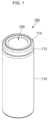
- FIG. 1 is a perspective view illustrating a secondary battery according to an embodiment of the present disclosure.
- FIG. 2 is a cross-sectional view of a secondary battery according to an embodiment of the present disclosure.
- FIG. 3 is an enlarged cross-sectional view of a cap plate in the secondary battery according to an embodiment of the present disclosure.
- the secondary battery 100 may include a cylindrical case 110, an electrode assembly 120, and a cap plate 130.
- the cylindrical case 110 may include a substantially circular bottom portion 111 and a sidewall 112 extending a predetermined length upward from the bottom portion 111.
- cylindrical case 110 may include or be referred to as a can, a casing, or a housing.
- the top portion of the cylindrical case 110 may be opened. Therefore, during the assembling process of the secondary battery, the electrode assembly 120 may be integrated into a single structure and inserted into the cylindrical case 110. Of course, the electrolyte may later be additionally injected into the cylindrical case 110.
- the cylindrical case 110 may be made of steel, a steel alloy, nickel-plated steel, a nickel-plated steel alloy, aluminum, or an aluminum alloy.
- the cylindrical case 110 may be provided with a beading part 113 recessed inward at a lower portion of the cap plate 130 and a crimping part 114 bent inward at an upper portion of the cap plate 130.
- the electrode assembly 120 may be accommodated inside the cylindrical case 110.
- the electrode assembly 120 may include or be referred to as an electrode, an electrode group, or a jelly roll.
- the electrode assembly 120 may include a negative electrode plate 121 coated with a negative electrode active material (e.g., graphite, carbon, etc.), and a positive electrode plate 122 coated with a positive electrode active material (e.g., transition metal oxide (LiCoO 2 , LiNiO 2 , LiMn 2 O 4 , etc.)), and a separator 123 positioned between the negative electrode plate 121 and the positive electrode plate 122 to prevent a short circuit and to allow only the movement of lithium ions.
- a negative electrode active material e.g., graphite, carbon, etc.
- a positive electrode plate 122 coated with a positive electrode active material e.g., transition metal oxide (LiCoO 2 , LiNiO 2 , LiMn 2 O 4 , etc.)
- a separator 123
- the negative electrode plate 121, the positive electrode plate 122, and the separator 123 may be wound in a substantially cylindrical shape.
- the negative electrode plate 121 may be a copper (Cu) foil
- the positive electrode plate 122 may be an aluminum (Al) foil
- the separator 123 may be polyethylene (PE) or polypropylene (PP).
- a negative electrode tab 124 protruding and extending downward by a predetermined length may be welded to the negative electrode plate 121, and a positive electrode tab 125 protruding and extending upward by a predetermined length may be welded to the positive electrode plate 122.
- the negative electrode tab 124 may be copper (Cu) or nickel (Ni), and the positive electrode tab 125 may be aluminum (Al).
- the negative electrode tab 124 of the electrode assembly 120 may be welded to the bottom portion 111 of the cylindrical case 110.
- the cylindrical case 110 may operate as a negative electrode.
- the negative electrode tab 124 may be ultrasonically welded to or laser welded to the bottom 111 of the cylindrical case 110.
- the positive electrode tab 125 may be welded to the bottom portion 111 of the cylindrical case 110, and in this case, the cylindrical case 110 may operate as a positive electrode.
- a first insulating plate 126 coupled to the cylindrical case 110 and having a first hole 126a in the center and a second hole 126b outside thereof may be interposed between the electrode assembly 120 and the bottom portion 111.
- the first insulating plate 126 prevents the electrode assembly 120 from electrically contacting the bottom portion 111 of the cylindrical case 110.
- the first insulating plate 126 prevents the positive electrode plate 122 of the electrode assembly 120 from electrically contacting the bottom portion 111.
- the first hole 126a allows the gas to quickly move upward through a center pin 140 when a large amount of gas is generated due to an abnormality of the secondary battery
- the second hole 126b allows the negative electrode tab 124 to pass through and be welded to the bottom portion 111.
- a second insulating plate 127 coupled to the cylindrical case 110 and having a first hole 127a in the center and a plurality of second holes 127b on the outside thereof may be interposed between the electrode assembly 120 and the cap plate 130.
- the second insulating plate 127 prevents the electrode assembly 120 from electrically contacting the cap plate 130.
- the second insulating plate 127 prevents the negative electrode plate 121 of the electrode assembly 120 from electrically contacting the cap plate 130.
- the first hole 127a allows the gas to quickly move to the cap plate 130 when a large amount of gas is generated due to an abnormality of the secondary battery, and the second hole 127b allows the positive electrode tab 125 to pass through and be welded to the cap plate 130.
- the remaining second holes 127b serve to allow an electrolyte to quickly flow into the electrode assembly 120 in the electrolyte injection process.
- the diameters of the first holes 126a and 127a of the first and second insulating plates 126 and 127 are smaller than the diameter of the center pin 140, so that the center pin 140 is prevented from electrically contacting the bottom portion 111 of the cylindrical case 110 or the cap plate 130 due to an external impact.
- the center pin 140 has a shape of a hollow circular pipe and may be coupled to an approximate center of the electrode assembly 120.
- the center pin 140 may be made of steel, stainless steel, aluminum, an aluminum alloy, or polybutylene terephthalate, but the material is not limited to those listed herein.
- the center pin 140 serves to suppress deformation of the electrode assembly 120 during charging and discharging of the secondary battery and serves as a passage for gas generated inside the secondary battery.
- the cap plate 130 seals the opening of the cylindrical case 110 to protect the electrode assembly 120 from the external environment, and when the internal pressure of the cylindrical case 110 is higher than a reference pressure (or the operating pressure of the cap plate), the cap plate 130 may be broken, and the internal gas of the cylindrical case 110 may be discharged to the outside.
- the cap plate 130 may also serve as a positive electrode terminal.
- the cap plate 130 may be made of aluminum or aluminum alloy.
- the cap plate 130 may include a first flat portion 131 that is substantially flat and located in the center, a second flat portion 132 that is located outside the first flat portion 131 and is substantially flat, and a vent portion 133 that is positioned between the first flat portion 131 and the second flat portion 132.
- the cap plate 130 may include or be referred to as a cap, a conductor plate, a bent plate, a cover, or a lid.
- thicknesses of the first flat portion 131 and the second flat portion 132 may have substantially similar or the same to each other.
- the first flat portion 131 is located at the center of the cap plate 130, and the positive electrode tab 125 of the electrode assembly 120 may be welded to a lower portion thereof.
- the lower surface of the first flat portion 131 may be ultrasonically welded to or laser welded to the positive electrode tab 125.
- the upper surface of the first flat portion 131 is exposed to the outside, i.e. it is part of the external surface of the battery, and may be electrically connected to an external device to serve as a terminal.
- the first flat portion 131 may have a thickness of 0.7 mm to 0.9 mm. If the thickness of the first flat portion 131 is smaller than 0.7 mm, a pin hole may be generated during welding of the cap plate 130 and the positive electrode tab 125, thereby reducing the bonding force between the two. In addition, if the thickness of the first flat portion 131 is greater than 0.9 mm, deformation distribution may occur during welding of the cap plate 130 and the positive electrode tab 125, thereby degrading the quality of the secondary battery 100.
- the secondary battery 100 can secure a welding margin by limiting the thickness of the first flat portion 131.
- the second flat portion 132 is positioned outside the first flat portion 131 and may be fixed to the cylindrical case 110 through an insulating gasket 150.
- the height of the second flat portion 132 may be higher than that of the first flat portion 131.
- An upper surface of the second flat portion 132 may be higher than an upper surface of the first flat portion 131 In other words, the upper surface of the second flat portion 132 and the upper surface of the first flat portion 131 are not located on the same plane. Accordingly, a height difference H is generated between the upper surface of the second flat portion 132 and the upper surface of the first flat portion 131.
- the height of a feature is defined as the distance of the feature from the bottom portion 111.
- the height difference between two features is defined as the difference of the respective heights of the two features.
- the distribution of the operating pressure of the cap plate 130 may be enhanced and/or improved.
- a height difference H between the upper surface of the second flat portion 132 and the upper surface of the first flat portion 131 may be 0.1 mm to 0.4 mm. If the height difference H between the upper surface of the second flat portion 132 and the upper surface of the first flat portion 131 is less than 0.1 mm or greater than 0.4 mm, deformation and breaking distribution of a part may occur during operating of the cap plate 130.
- the height difference H between the upper surface of the second flat portion 132 and the upper surface of the first flat portion 131 may be 0.15 mm to 0.35 mm. If the height difference H between the upper surface of the second flat portion 132 and the upper surface of the first flat portion 131 is 0.15 mm to 0.35 mm, deformation and breaking distribution as well as deformation distribution can be prevented from occurring during operating of the cap plate 130.
- the vent portion 133 may be positioned between the first flat portion 131 and the second flat portion 132.
- the vent portion 133 may be provided to have a thickness smaller than the first flat portion 131 and the second flat portion 132.
- the vent portion 133 may have a relatively smaller thickness than the first flat portion 131 and the second flat portion 132 by partially removing the lower surface of the cap plate 130.
- the vent portion 133 may be shaped of a ring spaced a certain distance apart from the center of the cap plate 130.
- vent portion 133 may be provided to be inclined by the height difference H between the first flat portion 131 and the second flat portion 132.
- the vent portion 133 may further include a notch 134 formed at a predetermined depth on the lower surface.
- the notch 134 may be formed in a continuous form along the lower surface of the vent portion 133.
- the secondary battery 100 provides only the cap plate 130 as a component that seals the upper portion of the cylindrical case 110 and eliminates the existing component having a current blocking function, thereby reducing internal resistance and reducing the weight of the secondary battery 100.
- the insulating gasket 150 may be interposed between the cap plate 130 and the cylindrical case 110.
- the insulating gasket 150 may insulate the cap plate 130 and the cylindrical case 110 from each other.
- the insulating gasket 150 may cover the outer circumference of the second flat portion 132 of the cap plate 130.
- the outer surface of the insulating gasket 150 may be in close contact with the beading part 113 and the crimping part 114, and the inner surface of the insulating gasket 150 may be in close contact with the second flat portion 132.
- the insulating gasket 150 may include or be referred to as a sealing gasket, an insulator, or resin.
- the insulating gasket 150 may be made of a resin material, such as polyethylene (PE), polypropylene (PP), polyethylene terephthalate (PET), etc., but the material is not limited thereto.
- a resin material such as polyethylene (PE), polypropylene (PP), polyethylene terephthalate (PET), etc., but the material is not limited thereto.
- FIGS. 4A and 4B are schematic views illustrating a method for manufacturing a cap plate in the secondary battery according to an embodiment of the present disclosure.
- a cap plate 130 in which a first flat portion 131 and a second flat portion 132 are positioned on the same plane is provided, and pressure is applied to the first flat portion 131, thereby manufacturing the cap plate 130 in which the upper surface of the second flat portion 132 is higher than the upper surface of the first flat portion 131.
- the thickness of the second flat portion 132 extending downward together with the vent portion 133 when the first flat portion 131 is pressed can be compensated for.
- the present disclosure provides a secondary battery capable of improving safety by discharging internal gas while preventing deformation of a cap plate including a vent portion when pressure inside the case increases.
Applications Claiming Priority (1)
| Application Number | Priority Date | Filing Date | Title |
|---|---|---|---|
| KR1020220002679A KR20230106935A (ko) | 2022-01-07 | 2022-01-07 | 이차 전지 |
Publications (2)
| Publication Number | Publication Date |
|---|---|
| EP4210139A2 true EP4210139A2 (fr) | 2023-07-12 |
| EP4210139A3 EP4210139A3 (fr) | 2023-10-11 |
Family
ID=84887278
Family Applications (1)
| Application Number | Title | Priority Date | Filing Date |
|---|---|---|---|
| EP23150630.4A Pending EP4210139A3 (fr) | 2022-01-07 | 2023-01-06 | Batterie secondaire |
Country Status (4)
| Country | Link |
|---|---|
| US (1) | US20230223622A1 (fr) |
| EP (1) | EP4210139A3 (fr) |
| KR (1) | KR20230106935A (fr) |
| CN (1) | CN116417720A (fr) |
Family Cites Families (3)
| Publication number | Priority date | Publication date | Assignee | Title |
|---|---|---|---|---|
| KR20190138509A (ko) * | 2018-06-05 | 2019-12-13 | 주식회사 엘지화학 | 이차전지 |
| EP3913701B1 (fr) * | 2019-01-18 | 2023-08-16 | Panasonic Energy Co., Ltd. | Batterie étanche |
| US20220407157A1 (en) * | 2019-11-29 | 2022-12-22 | Sanyo Electric Co., Ltd. | Sealed battery |
-
2022
- 2022-01-07 KR KR1020220002679A patent/KR20230106935A/ko unknown
-
2023
- 2023-01-06 US US18/151,172 patent/US20230223622A1/en active Pending
- 2023-01-06 EP EP23150630.4A patent/EP4210139A3/fr active Pending
- 2023-01-09 CN CN202310028353.1A patent/CN116417720A/zh active Pending
Also Published As
| Publication number | Publication date |
|---|---|
| US20230223622A1 (en) | 2023-07-13 |
| KR20230106935A (ko) | 2023-07-14 |
| EP4210139A3 (fr) | 2023-10-11 |
| CN116417720A (zh) | 2023-07-11 |
Similar Documents
| Publication | Publication Date | Title |
|---|---|---|
| US20220255204A1 (en) | Secondary battery | |
| US20230249288A1 (en) | Secondary battery | |
| EP1804311A1 (fr) | Batterie secondaire à ions de lithium cylindrique | |
| KR102570969B1 (ko) | 원통형 리튬 이온 이차 전지 | |
| US20240097291A1 (en) | Cylindrical lithium ion secondary battery | |
| US11664523B2 (en) | Secondary battery | |
| KR20210006202A (ko) | 이차 전지 | |
| US8241781B2 (en) | Cylinder type lithium ion secondary battery | |
| EP4148879A1 (fr) | Batterie secondaire cylindrique | |
| EP4210139A2 (fr) | Batterie secondaire | |
| EP4254579A1 (fr) | Batterie secondaire | |
| KR102561215B1 (ko) | 이차 전지 | |
| US20230223643A1 (en) | Secondary battery | |
| US20230231284A1 (en) | Secondary battery | |
| KR102661207B1 (ko) | 이차 전지 | |
| US20230231242A1 (en) | Secondary battery | |
| US20240145853A1 (en) | Secondary battery | |
| EP4250445A1 (fr) | Batterie secondaire et son procédé de fabrication | |
| EP4123814A1 (fr) | Batterie secondaire cylindrique | |
| KR20230147883A (ko) | 이차 전지 | |
| KR20230063612A (ko) | 원통형 이차전지 및 이차전지의 제조방법 | |
| CN116073063A (zh) | 圆柱形二次电池和用于制造该圆柱形二次电池的方法 |
Legal Events
| Date | Code | Title | Description |
|---|---|---|---|
| PUAI | Public reference made under article 153(3) epc to a published international application that has entered the european phase |
Free format text: ORIGINAL CODE: 0009012 |
|
| STAA | Information on the status of an ep patent application or granted ep patent |
Free format text: STATUS: REQUEST FOR EXAMINATION WAS MADE |
|
| 17P | Request for examination filed |
Effective date: 20230106 |
|
| AK | Designated contracting states |
Kind code of ref document: A2 Designated state(s): AL AT BE BG CH CY CZ DE DK EE ES FI FR GB GR HR HU IE IS IT LI LT LU LV MC ME MK MT NL NO PL PT RO RS SE SI SK SM TR |
|
| PUAL | Search report despatched |
Free format text: ORIGINAL CODE: 0009013 |
|
| AK | Designated contracting states |
Kind code of ref document: A3 Designated state(s): AL AT BE BG CH CY CZ DE DK EE ES FI FR GB GR HR HU IE IS IT LI LT LU LV MC ME MK MT NL NO PL PT RO RS SE SI SK SM TR |
|
| RIC1 | Information provided on ipc code assigned before grant |
Ipc: H01M 50/342 20210101ALI20230901BHEP Ipc: H01M 50/152 20210101ALI20230901BHEP Ipc: H01M 10/04 20060101AFI20230901BHEP |