EP4209826A1 - High-confidence optical head pose correspondence mapping with multiple markers for high-integrity headtracking on a headworn display (hwd) - Google Patents
High-confidence optical head pose correspondence mapping with multiple markers for high-integrity headtracking on a headworn display (hwd) Download PDFInfo
- Publication number
- EP4209826A1 EP4209826A1 EP23150052.1A EP23150052A EP4209826A1 EP 4209826 A1 EP4209826 A1 EP 4209826A1 EP 23150052 A EP23150052 A EP 23150052A EP 4209826 A1 EP4209826 A1 EP 4209826A1
- Authority
- EP
- European Patent Office
- Prior art keywords
- density
- head pose
- fiducials
- medium
- initial
- Prior art date
- Legal status (The legal status is an assumption and is not a legal conclusion. Google has not performed a legal analysis and makes no representation as to the accuracy of the status listed.)
- Granted
Links
Images






Classifications
-
- G—PHYSICS
- G06—COMPUTING OR CALCULATING; COUNTING
- G06T—IMAGE DATA PROCESSING OR GENERATION, IN GENERAL
- G06T7/00—Image analysis
- G06T7/70—Determining position or orientation of objects or cameras
- G06T7/73—Determining position or orientation of objects or cameras using feature-based methods
- G06T7/74—Determining position or orientation of objects or cameras using feature-based methods involving reference images or patches
-
- G—PHYSICS
- G06—COMPUTING OR CALCULATING; COUNTING
- G06F—ELECTRIC DIGITAL DATA PROCESSING
- G06F3/00—Input arrangements for transferring data to be processed into a form capable of being handled by the computer; Output arrangements for transferring data from processing unit to output unit, e.g. interface arrangements
- G06F3/01—Input arrangements or combined input and output arrangements for interaction between user and computer
- G06F3/011—Arrangements for interaction with the human body, e.g. for user immersion in virtual reality
- G06F3/012—Head tracking input arrangements
-
- G—PHYSICS
- G06—COMPUTING OR CALCULATING; COUNTING
- G06V—IMAGE OR VIDEO RECOGNITION OR UNDERSTANDING
- G06V10/00—Arrangements for image or video recognition or understanding
- G06V10/20—Image preprocessing
- G06V10/24—Aligning, centring, orientation detection or correction of the image
- G06V10/245—Aligning, centring, orientation detection or correction of the image by locating a pattern; Special marks for positioning
-
- G—PHYSICS
- G06—COMPUTING OR CALCULATING; COUNTING
- G06V—IMAGE OR VIDEO RECOGNITION OR UNDERSTANDING
- G06V20/00—Scenes; Scene-specific elements
- G06V20/50—Context or environment of the image
- G06V20/52—Surveillance or monitoring of activities, e.g. for recognising suspicious objects
-
- G—PHYSICS
- G06—COMPUTING OR CALCULATING; COUNTING
- G06V—IMAGE OR VIDEO RECOGNITION OR UNDERSTANDING
- G06V40/00—Recognition of biometric, human-related or animal-related patterns in image or video data
- G06V40/10—Human or animal bodies, e.g. vehicle occupants or pedestrians; Body parts, e.g. hands
-
- G—PHYSICS
- G02—OPTICS
- G02B—OPTICAL ELEMENTS, SYSTEMS OR APPARATUS
- G02B27/00—Optical systems or apparatus not provided for by any of the groups G02B1/00 - G02B26/00, G02B30/00
- G02B27/0093—Optical systems or apparatus not provided for by any of the groups G02B1/00 - G02B26/00, G02B30/00 with means for monitoring data relating to the user, e.g. head-tracking, eye-tracking
-
- G—PHYSICS
- G02—OPTICS
- G02B—OPTICAL ELEMENTS, SYSTEMS OR APPARATUS
- G02B27/00—Optical systems or apparatus not provided for by any of the groups G02B1/00 - G02B26/00, G02B30/00
- G02B27/01—Head-up displays
- G02B27/017—Head mounted
-
- G—PHYSICS
- G06—COMPUTING OR CALCULATING; COUNTING
- G06T—IMAGE DATA PROCESSING OR GENERATION, IN GENERAL
- G06T2207/00—Indexing scheme for image analysis or image enhancement
- G06T2207/30—Subject of image; Context of image processing
- G06T2207/30196—Human being; Person
-
- G—PHYSICS
- G06—COMPUTING OR CALCULATING; COUNTING
- G06T—IMAGE DATA PROCESSING OR GENERATION, IN GENERAL
- G06T2207/00—Indexing scheme for image analysis or image enhancement
- G06T2207/30—Subject of image; Context of image processing
- G06T2207/30204—Marker
Definitions
- the medium-density fiducials 102, 104, 106 include coded features, the identity of each medium-density fiducial 102, 104, 106 and their specific locations and orientations are a critical factor. However, because the low-density fiducials 108, 110 do not include coded features (and may be identical to each other), only the specific location of each low-density fiducial 108, 110 is a critical factor. It may be noted, however, that in some embodiments low-density fiducials 108, 110 may convey orientational information as well as positional information.
- the collection of medium-density fiducials 102, 104, 106 and the low-density fiducials 108, 110 form a constellation of markers.
- the medium-density fiducials 102, 104, 106 and the low-density fiducials 108, 110 have a specific geometry in that each medium-density fiducial 102, 104, 106 and low-density fiducial 108, 110 has a unique spatial relationship, e.g., a unique relative position and orientation, with every other fiducial.
- the spatial relationships between a constellation of fiducials may be referred to as a marker geometry of the constellation.
- the system 200 may either disregard, or attempt to resolve, the ambiguity.
- the system 200 may have enough data and measurements to discard any ambiguous features detected within the region of ambiguity 606 without any negative consequences with respect to the accuracy or integrity of the estimated head pose.
- the system 200 may also track the low-density fiducials 602b, 602c and the region of ambiguity 606 as alternative hypotheses, performing a first correspondence calculation with one low-density fiducial 602b, a second correspondence calculation with the other low-density fiducial 602c, and assessing both correspondence ambiguities for feasibility or viability.
- the set of feasible correspondence ambiguities may be tracked in a similar manner to U.S. Patent Application No. 17/685,032 , which application is hereby incorporated by reference in its entirety.
- the initial head pose estimate may also be determined via a coasted head pose solution.
- a previous head pose solution at a previous time of validity may be used as an initial pose estimate for the current time of validity (e.g., either a zero-order hold without rate information or propagated forward in time via extended Kalman filter propagation, as disclosed by U.S. Patent No. 10,216,265 , which Patent is herein incorporated by reference in its entirety).
- the use of a coasted solution may introduce additional error that the error bound for the resulting head pose solution must account for.
- historical information from the coasted solution and information from the current 2D image may be combined in order to calculate a tightly coupled head pose estimate as described below.
- a coasted head pose solution alone may be used to calculate a head pose estimate when no medium-density fiducials 502, 504, 506, 508 are detected in the captured 2D image.
- the system 200 may check the medium-density fiducials 502, 504, 506, 508 detected within the image data 702 for other feasible correspondences 710 to the known 3D pose data of the medium-density fiducials. If, for example, the only feasible correspondence between 2D detected fiducials and 3D real-world fiducials is the correspondence informing the high integrity head pose estimate 706, the high integrity head pose estimate may be a valid snapshot head pose estimate 712. However, if other feasible correspondences 710 exist, if one or more ambiguous correspondences between detected medium density fiducials 502, 504, 506, 508 and their 3D constellation data 704, the system 200 must discard or resolve any ambiguous correspondences as disclosed above.
- the system 200 may consider as a candidate initial head pose estimate the snapshot head pose estimate 712 determined as shown by FIG. 7A .
- the snapshot head pose estimate 712 may be determined at a current time of validity based on a grouping of medium-density fiducials 502, 504, 506, 508 detected in the 2D image data 702.
- the snapshot head pose estimate 712 may be preferred due to its temporal proximity to the display time of the corresponding image data and/or symbology by the HWD.
- the snapshot head pose estimate 712 may be unavailable or unusable.
- the head tracker system refines the initial head pose estimate and/or the initial error bound based on the identified search areas. For example, additional medium-density and low-density fiducials detected within their corresponding search areas (i.e., where the initial head pose estimate says they should be) may enhance the accuracy of the initial head pose estimate. Similarly, if correspondence ambiguities are found between fiducial markers and their corresponding search areas, e.g., if a particular fiducial may be located within one or more overlapping search areas, the accuracy of the initial head pose estimate will be adversely affected and the correspondence ambiguities must either be discarded (if possible) or accounted for in the final head pose solution and error bound (see, e.g., FIGS.
- the head tracker system discards the initial head pose estimate.
- the head tracker system may select an alternative head pose estimate, e.g., a coasted or tightly coupled head pose solution refinable to a higher level of accuracy.
Landscapes
- Engineering & Computer Science (AREA)
- Theoretical Computer Science (AREA)
- Physics & Mathematics (AREA)
- General Physics & Mathematics (AREA)
- General Engineering & Computer Science (AREA)
- Human Computer Interaction (AREA)
- Multimedia (AREA)
- Computer Vision & Pattern Recognition (AREA)
- Length Measuring Devices By Optical Means (AREA)
Abstract
Description
- This application relates to U.S. Patent No.
US10909715B1, filed January 31, 2019 - This application relates to
U.S. Patent Application No. 17/573,283, filed March 2, 2042 - This application relates to
U.S. Patent Application No. 17/685,032, filed March 2, 2042 - The subject matter disclosed herein is directed generally to head-worn display (HWD) systems for aircraft pilots, and more particularly to head tracking systems for estimating head pose of the pilot wearing the HWD.
- For display of an accurately aligned presentation on a Head Worn Display (HWD) or Helmet Mounted Display (HMD), the HWD must properly convert flight guidance cues into the head reference frame to allow pilot to virtually and accurately "see" a displayed presentation. In order for the HWD to accurately present the guidance cues, the HWD must be aligned to determine a relative position and orientation of the wearer's head, e.g., a head pose, to display the information in the accurate position on the HWD. If an inaccurate head pose is used to convert safety-critical data in the head frame, the data may likewise be displayed inaccurately, potentially including Hazardously Misleading Information (HMI) associated with a safety risk.
- Traditionally, one or more high-density fiducials have been used to determine head pose of a pilot. The need for a high-integrity optical head pose via a sufficient correspondence integrity resulted in the use of high-density fiducials, which incorporate a sufficiently dense amount of encoded information so as to appear individually distinct from other fiducials as well as from patterns in the background.
- However, higher information density fiducials may result in lower detectability. Detectability of fiducials is determined in part by the fiducial's internal features relative to the overall size of the fiducial. As a result, increasing the density of bits within an individual fiducial of consistent size in order to increase correspondence integrity makes these bits and features more difficult to detect.
- As detectability of individual fiducials decreases, so does the likelihood of the fiducials being detected by a camera, as it may be more difficult for the camera to capture the distinguishing features of said fiducial with sufficient pixel accuracy. A need remains for a system and method which may overcome these limitations and provide a novel solution to enable high-integrity head pose tracking, without issues resulting from densely packed fiducials that reduce detectability.
- Conventionally, an image of a high-density fiducial is captured by a camera and used for pose estimation, e.g., by detecting the relative location of the fiducial in-frame and determining the extent to which the relative location of the fiducial corresponds to a known three-dimensional (3D) position and orientation of that fiducial, e.g., where we know a particular fiducial to be. However, the overall snapshot correspondence integrity requirement is conservatively imposed on each fiducial, as either the fiducial is detected or it is not.
- A system for high-integrity head pose estimation is disclosed. In embodiments, the system includes a helmet, which comprises a head worn display (HWD) and one or more cameras, the cameras configured to capture one or more 2-dimensional (2D) images associated with the HWD. The system includes three or more unique medium-density fiducials and one or more low-density fiducial, where the fiducials are configured to be captured in the one or more 2D images. The system includes one or more memory configured to store program instructions for determining an estimated head pose. The system includes a data storage element configured to store a 3-dimensional (3D) constellation of position and orientation of the three or more medium-density fiducials and the one or more ow-density fiducials. The system includes one or more processor, communicatively coupled to the one or more camera, the data storage element, and the one or more memory. In an embodiment, the processor is configured to receive one or more images from the camera, the 3D constellation of the position and the orientation of the three or more medium-density fiducials and the one or more low-density fiducials, and the program instructions, where the processor executes the program instructions to estimate a current head pose.
- In some embodiments, the medium-density fiducials of the system are ArUco markers. In an embodiment, the ArUco markers are 4x4 ArUco markers.
- A method for high-integrity head pose estimation is also disclosed. In embodiments, the method includes receiving one or more 2D images captured with a camera, where the 2D images comprise three or more unique medium-density fiducials and one or more low density fiducials. The method includes detecting medium-density fiducials within the one or more images and making an initial estimate of a current head pose based on the detectable medium-density fiducials. The method includes determining if the initial estimate of the current head pose is the only feasible correspondence based upon a relationship of the detectable medium-density fiducials and a 3D constellation, where alternative correspondences for the initial estimate invalidate the initial estimation. The method includes selecting an initial head pose estimate from either the ArUco initial estimate of the current head pose, a tightly coupled head pose estimate, or a coasted head pose. The method includes determining a search area in the initial head pose estimate for at least one of the three or more medium-density fiducials or the one or more low density fiducials. The method includes searching the image associated with the initial head pose estimate for the selected three or more medium-density fiducials or the one or more low-density fiducial. The method includes determining whether the three or more medium-density fiducials or the one or more low-density fiducial are within their search area. The method includes accepting the initial head pose estimate as a final head pose estimate if the three or more medium-density fiducials or the one or more low-density fiducial are within their search area or rejecting the initial head pose estimate if three or more medium-density fiducials or the one or more low-density fiducial are not within their search area.
- In some embodiments, the medium-density fiducials of the system are ArUco markers. In an embodiment, the ArUco markers are 4x4 ArUco markers.
- In some embodiments, the tightly coupled head pose estimate is formed by combing one or more detectable medium-density fiducials and a coasted head pose.
- In some embodiments, the tightly coupled head pose is the final head pose estimate.
- This Summary is provided solely as an introduction to subject matter that is fully described in the Detailed Description and Drawings. The Summary should not be considered to describe essential features nor be used to determine the scope of the Claims. Moreover, it is to be understood that both the foregoing Summary and the following Detailed Description are example and explanatory only and are not necessarily restrictive of the subject matter claimed.
- The detailed description is described with reference to the accompanying figures. The use of the same reference numbers in different instances in the description and the figures may indicate similar or identical items. Various embodiments or examples ("examples") of the present disclosure are disclosed in the following detailed description and the accompanying drawings. The drawings are not necessarily to scale. In general, operations of disclosed processes may be performed in an arbitrary order, unless otherwise provided in the claims. In the drawings:
-
FIG. 1 shows a deployment of medium-density fiducials and low-density fiducials on a helmet, in accordance with example embodiments of this disclosure; -
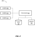
FIG. 2 is a block diagram illustrating a configuration for processing images, in accordance with example embodiments of this disclosure; -
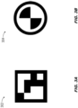
FIG. 3A shows a medium-density fiducial, in accordance with example embodiments of this disclosure; -
FIG. 3B shows a low-density fiducial, in accordance with example embodiments of this disclosure; -
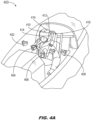
FIG. 4A shows a single camera in a cockpit detecting medium-density fiducials and low-density fiducials on a pilot's helmet, in accordance with example embodiments of this disclosure; -
FIG. 4B shows multiple cameras in a cockpit detecting medium-density fiducials and low-density fiducials on a pilot's helmet, in accordance with example embodiments of this disclosure; -
FIG. 4C shows a camera on a helmet detecting medium-and low-density fiducials placed in the cockpit, in accordance with example embodiments of this disclosure; -
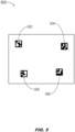
FIG. 5 shows a 2D image of multiple medium-density fiducials, in accordance with example embodiments of this disclosure; -
FIG. 6 shows a 2D image of multiple medium-density fiducials and low-density fiducials, with search areas defined for the low-density fiducials, in accordance with example embodiments of this disclosure; -
FIG. 7A is a block diagram illustrating the determination of an initial head pose estimate at a current time of validity, in accordance with example embodiments of this disclosure; -
FIG. 7B is a block diagram illustrating the selection of multiple candidate initial head pose estimates, in accordance with example embodiments of this disclosure; -
FIG. 7C is a block diagram illustrating the determination of a final head pose estimate, in accordance with example embodiments of this disclosure; and -
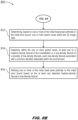
FIG. 8A-8D is a flow diagram depicting steps for forming a head pose estimate, in accordance with example embodiments of this disclosure. - Before explaining one or more embodiments of the disclosure in detail, it is to be understood that the embodiments are not limited in their application to the details of construction and the arrangement of the components or steps or methodologies set forth in the following description or illustrated in the drawings. In the following detailed description of embodiments, numerous specific details may be set forth in order to provide a more thorough understanding of the disclosure. However, it will be apparent to one of ordinary skill in the art having the benefit of the instant disclosure that the embodiments disclosed herein may be practiced without some of these specific details. In other instances, well-known features may not be described in detail to avoid unnecessarily complicating the instant disclosure.
- As used herein a letter following a reference numeral is intended to reference an embodiment of the feature or element that may be similar, but not necessarily identical, to a previously described element or feature bearing the same reference numeral (e.g., 1, 1a, 1b). Such shorthand notations are used for purposes of convenience only and should not be construed to limit the disclosure in any way unless expressly stated to the contrary.
- Further, unless expressly stated to the contrary, "or" refers to an inclusive or and not to an exclusive or. For example, a condition A or B is satisfied by any one of the following: A is true (or present) and B is false (or not present), A is false (or not present) and B is true (or present), and both A and B are true (or present).
- In addition, use of "a" or "an" may be employed to describe elements and components of embodiments disclosed herein. This is done merely for convenience and "a" and "an" are intended to include "one" or "at least one," and the singular also includes the plural unless it is obvious that it is meant otherwise.
- Finally, as used herein any reference to "one embodiment" or "some embodiments" means that a particular element, feature, structure, or characteristic described in connection with the embodiment is included in at least one embodiment disclosed herein. The appearances of the phrase "in some embodiments" in various places in the specification are not necessarily all referring to the same embodiment, and embodiments may include one or more of the features expressly described or inherently present herein, or any combination or sub-combination of two or more such features, along with any other features which may not necessarily be expressly described or inherently present in the instant disclosure.
- Broadly speaking, embodiments of the inventive concepts disclosed herein are directed to a system and method for determining a high integrity head pose using optical pose estimation that are reliable for safety critical applications using multiple medium-density fiducials and low-density fiducials. Optical pose refers to the position and orientation of the HWD camera relative to the reference frame of the fiducials. For example, in an inside-out configuration wherein the camera is fixed to an HWD worn by an aircraft pilot and the fiducials are arranged in fixed positions and orientations around the aircraft (e.g., within a cockpit or control area within view of the camera), the optical pose may be in a camera-centered reference frame (camera frame) relative to a fiducial marker-centered reference frame (marker frame). Given a rigid body-head alignment between the camera frame and the head frame, and a platform alignment between the marker frame and a platform frame centered on the aircraft (also called a body frame), a head pose relative to the platform frame may be determined based on the optical pose. Similarly, in an outside-in configuration where the camera or cameras are mounted in the cockpit and oriented toward the wearer, and the fiducials are attached to the head of the wearer, the head pose may be computer given a rigid body-head alignment between the marker and head frames and a platform alignment between the platform and camera frames.
- There is a need for high confidence correspondence between points seen in a 2-Dimensional (2D) image and points in a 3-Dimensional (3D) constellation of points of the real world. If the points in the 2D image cannot be precisely mapped to the real-
world 3D objects portrayed in the 2D image, a correspondence integrity event (CIE) may result. For example, if there are ambiguities between the 2D location and orientation of fiducials (e.g., fiducials captured by a camera aligned with the current head pose) and the absolute 3D locations of those fiducials, the head tracker cannot determine the current head pose in the 3D reference frame with sufficient integrity for safety critical applications. For safety critical applications, a head pose estimate may be required to have an integrity bound of 1e-7, i.e., a probability of at most .0000001 (.00001 percent) that the head pose estimate error is large enough to be hazardously misleading. In applications regarding aircraft, these problems, no matter how slight, may have potentially deleterious (e.g., minor, major, hazardous, catastrophic) outcomes. A camera and known markers may be used to estimate an optical pose (e.g., position and orientation) of a HWD based on a correspondence between a 2D image and a known 3D constellation. - When determining a head pose, a camera, or multiple cameras, may capture a 2D image portraying an arrangement of any number of fiducials (e.g., 3 or 4) at a single point in time. The captured image, and the fiducials captured therein, may then be compared to 3D constellation data including the known locations of each fiducial in order to determine a high confidence head pose. The determined head pose may then be used to orient an image displayed on a head worn display (HWD).
- Referring to
FIG. 1 , an environmental view of ahelmet 100 including medium-density fiducials density fiducials helmet 100 is intended for use in a head tracking system (e.g., a head tracker), medium-density fiducials density fiducials density fiducials density fiducial density fiducials density fiducial density fiducials - In embodiments, medium-
density fiducials density fiducial density fiducial - Additionally, the collection of medium-
density fiducials density fiducials density fiducials density fiducials density fiducial density fiducial - While embodiments of the present disclosure may show the head tracker integrated or used with an HWD in a
helmet 100, this example is intended to be illustrative rather than restrictive. For example, the head tracker disclosed herein may be used with any system displaying information to a user, including, but not limited to, a visor, goggles, augmented reality (AR) system, mixed reality (MR) system, virtual reality (VR) system, or the like. - Referring to
FIG. 2 , a block diagram of asystem 200 for implementing exemplary embodiments of the inventive concepts disclosed herein is shown. Thesystem 200 includes aprocessor 202, amemory 204 connected to theprocessor 202 for embodying processor executable code (e.g., program instructions), adata storage element 206 storing data specific to medium-density fiducials and low-density fiducials (e.g., a constellation database of 3D constellations of points), and one ormore cameras processor 202 is configured to receive images of the medium-density fiducials and low-density fiducials from the one ormore cameras data storage element 206, and use the data to make determinations about the feasibility and accuracy of a resulting head pose calculation as more fully described herein. In an embodiment, thememory 204 and thedata storage element 206 may be a singular element, storing both program instructions and information (e.g., a constellation database) relating to medium-density fiducials and low-density fiducials. The 3D constellation database may include the unique position and/or orientation of each medium-density and low-density fiducial in 3D space (e.g., relative to a common marker frame). Theprocessor 202 may be communicatively coupled to thememory 204, thedata storage element 206, and the one ormore cameras - Referring to
FIG. 3A , a medium-density fiducial 302 is shown. In an embodiment, the medium-density fiducials 302 may be an Augmented Reality University of Cordoba (ArUco) marker. For example, the medium-density fiducial 302 may be a 4x4 ArUco marker. In embodiments, each medium-density fiducial 302 may be unique and include an encoded identifier, e.g., bits of information or features that make each medium-density fiducial 302 unique from every other medium-density fiducial 302. For example, the medium-density fiducial 302 may include an encoded pattern decodable to a unique 16-bit binary, e.g., 0111100111001101. The bits of information and features of each medium-density fiducial 302 are used by theprocessor 202 in conjunction with the method disclosed herein to help determine a high integrity head pose. - Referring to
FIG. 3B , a low-density fiducial 304 is shown. Each low-density fiducial 304 may contain no encoded bits in that each low-density fiducial may be indistinct from any other low-density fiducial 304; for example, to the extent that the low-density fiducial includes an encoded pattern, each low-density fiducial approximates the same binary, e.g., 1001. In embodiments, low-density fiducials 304 may be designed to as to be distinct from their background environment and detectable therein, in order to reduce or preclude spurious feature detection, e.g., where a non-fiducial background element is erroneously detected as a fiducial marker. Further, low-density fiducials 304 may additionally convey orientation information. On their own, low-density fiducials 304 are not capable of being used to determine a high-integrity head pose, however, when combined with medium-density fiducials 302, the positions and/or orientations of low-density fiducials may be used to provide a refined head pose solution wherein overall confidence or accuracy may be increased. - Broadly speaking, in embodiments medium-
density fiducials 302 may be implemented such that each medium-density fiducial of a set thereof has a significant bit difference between all other fiducials, but not so significant as to meet correspondence integrity requirements on a per-marker basis, as would a high-density fiducial. In embodiments, with respect to medium-density fiducials, correspondence integrity may be determined based on a combination of encoded marker identifiers and feasible marker geometry. For example, is a relative position of a fiducial or constellation thereof (or a portion of said constellation) as captured by an image feasible, given the known poses of each fiducial and the marker geometry (e.g., relative marker poses) of the constellation? In embodiments, with respect to low-density fiducials 304, correspondence integrity may be established based on high-confidence search areas within the image, and a low probability of spurious feature detection therein. For example, if a feature is detected within a high-confidence search area of a captured image, it must be a low-density fiducial 302 rather than a non-marker. - Referring now to
FIGS. 4A ,4B , and4C , environmental views of anaircraft cockpit 400 including exemplary embodiments of the inventive concepts disclosed herein are shown. - Referring to
FIGS. 4A and4B , anaircraft cockpit 400 including one ormore cameras density fiducials density fiducial density fiducial density fiducial FIG. 2 ). In embodiments (as shown byFIG. 4A ), asingle camera 404 may detect the three or more medium-density fiducials density fiducial FIG. 4B )multiple cameras density fiducials density fiducials processor 202 to perform a head pose estimation based on a composite image. A system where fiducials are disposed on ahelmet 100 andcameras cockpit 400 may be referred to as an outside-in approach to a head tracking system. - Referring to
FIG. 4C , an alternative embodiment is shown. While inFIGS. 4A and4B , one ormore cameras aircraft cockpit 400,FIG. 4C depicts one ormore cameras 402 mounted on a helmet. In this instance, the three or more medium-density fiducials density fiducials aircraft cockpit 400. An embodiment of thehead tracking system 200 wherein acamera 402 is mounted on ahelmet 100, or otherwise to the HWD, and fiducials are located throughout the cockpit 400 (e.g., within the field of view of the camera 402) may be referred to as an inside out implementation of the head tracking system. - In embodiments, each of the medium-
density fiducials density fiducials density fiducial density fiducial data storage element 206; for example, the constellation database may be referenced to determine or validate a head pose estimate as described below. - Referring to
FIG. 5 , a first part of a fiducial layout 500 (e.g., an image or portion thereof captured by the camera (402,FIG. 4A-C ) for estimating a head pose from three or more medium-density fiducials density fiducials - In embodiments, when solving for head pose, each of the medium-
density fiducials density fiducials density fiducial density fiducial - When solving for head pose using a collection of medium-
density fiducials - Referring to
FIG. 6 , thefiducial layout 600 may be implemented and may function similarly to thefiducial layout 500 ofFIG. 5 , except that within thefiducial layout 600, in addition to the four unique medium-density fiducials density fiducials 602a-602f and/orsearch areas 604a-604f may also be detected based on the initial head pose estimate. For example, unlike the medium-density fiducials density fiducials 602a-602f may be indistinct from one another in terms of their interior features and/or relative orientation. 602ln embodiments, eachsearch area 604a-604f (e.g., image region, pixel location) may be associated with a high-confidence head pose error bound indicative of a range where each low-density fiducial 602a-602f should be located. It should be noted, though it is not shown, that in embodiments an associated search area may be calculated for each of the medium-density fiducials density fiducials 602a-f. - In embodiments, the low-
density fiducials 602a-f may be used together with the initial head pose estimate based on detected medium-density fiducials density fiducials 602a-f to improve, refine, accept, or reject an initial head pose estimate, there may be a region ofambiguity 606 with respect to thesearch areas 604a-f. In a region ofambiguity 606 two ormore search areas density fiducials ambiguity 606. In a situation where there is a region ofambiguity 606, it is possible for the system confuse two or more low-density fiducials - In embodiments, when a region of
ambiguity 606 exists, thesystem 200 may either disregard, or attempt to resolve, the ambiguity. For example, thesystem 200 may have enough data and measurements to discard any ambiguous features detected within the region ofambiguity 606 without any negative consequences with respect to the accuracy or integrity of the estimated head pose. Alternatively, thesystem 200 may also track the low-density fiducials ambiguity 606 as alternative hypotheses, performing a first correspondence calculation with one low-density fiducial 602b, a second correspondence calculation with the other low-density fiducial 602c, and assessing both correspondence ambiguities for feasibility or viability. In embodiments, where multiple feasible correspondences remain, the set of feasible correspondence ambiguities may be tracked in a similar manner toU.S. Patent Application No. 17/685,032 , which application is hereby incorporated by reference in its entirety. - In embodiments, the feasibility of each of a set of correspondence ambiguities may be determined via reprojection. For example, a captured 2D image corresponding to the
fiducial layouts FIGS. 5 and6 may be reprojected onto a corresponding3D constellation data 704. Further, a chi-squared hypothesis test may be performed to determine if the reprojected medium-density fiducials - In embodiments, the set of
search regions 604a-604f may serve as an error bound for the set of all feasible correspondence ambiguities. For example, as noted above, asearch region 604b-604c may feasibly correspond to one or more low-density fiducials 602b-602c. Alternatively, a single low-density fiducial 602c may feasibly correspond tomultiple search regions 604b-604c, but it may impossible to determine with sufficient confidence to which of the possible search regions the low-density fiducial corresponds. Accordingly, a set of conditional pose solutions may be determined including a feasible head pose solution corresponding to each feasible correspondence ambiguity, e.g., based on said correspondence being the correct correspondence. Further, the set of conditional pose solutions may include a containment pose error bound, bounding the probability that the set of feasible correspondence ambiguities includes the correct correspondence (e.g., and the candidate head pose solution based on said correct correspondence). - In embodiments, the initial head pose estimate with high confidence error bounds, which may be used in turn to determine the
search regions 604a-604f, may be determined in several ways. For example, a snapshot head pose estimate may be based on medium-density fiducials density fiducials 602a-f within their correspondingsearch areas 604a-f. - In some embodiments, the initial head pose estimate may also be determined via a coasted head pose solution. For example, a previous head pose solution at a previous time of validity may be used as an initial pose estimate for the current time of validity (e.g., either a zero-order hold without rate information or propagated forward in time via extended Kalman filter propagation, as disclosed by
U.S. Patent No. 10,216,265 - In some embodiments, a coasted head pose solution alone may be used to calculate a head pose estimate when no medium-
density fiducials - In some embodiments a tightly coupled head pose estimate may be preferable to a snapshot head pose estimate. For example, if an insufficient number of medium-density or low-density fiducials (e.g., medium-density fiducial 502) is detected in a particular 2D image at a given time, it may not be possible to compute a snapshot head pose estimate with sufficient accuracy or confidence. In embodiments, a tightly coupled head pose estimate may be performed based on a coasted head pose solution and an otherwise insufficient number of medium-
density fiducials density fiducials 502 in the 2D image as predicted by the coasted head pose solution with the detected position of the medium-density fiducial within the captured 2D image. For example, the coasted head pose solution may have predicted the location of the detected medium-density fiducial 502 at pixel 150, while the detected medium-density fiducial 502 may have been detected at pixel 250 in the 2D image. In embodiments, the resulting 100-pixel residual may then be used to correct for possible errors in head pose and calculate a tightly coupled head pose estimate. For example, the correction in the head pose estimate may shift the coasted head pose solution such that the location of the medium-density fiducial 502 predicted by the coasted head pose solution becomes close to or aligned with the detected medium-density fiducial 502 of the 2D image. - Referring now to
FIGS. 7A-7C , block diagrams are shown, depicting the calculation of a head pose estimate by embodiments of thehead tracker system 200. - Referring in particular to
FIG. 7A , a block diagram for determining a high integrity head pose from medium-density fiducials is shown (e.g., medium-density fiducials FIG. 4C ) capturesimage data 702 corresponding to a 3D truth scene of an aircraft cockpit 400 (e.g., or other like environment surrounding the user/wearer of the HWD and wherein the medium-density fiducials 502-508 and/or low-density fiducials 602a-602f may be found) as captured by the 2D HWD camera. For example, theimage data 702 captured by theHWD camera 402 may contain medium-density fiducials aircraft cockpit 400. - In embodiments, the
head tracker system 200 may analyze the capturedimage data 702 to detect and identify medium-density fiducials density fiducials 2D image data 702 may be mapped to 2D relative locations within the image data and compared with to the 3D positions and orientations of each medium-density fiducial (e.g., and relative marker geometry) as provided byconstellation data 704. Based on correspondences between detected medium-density fiducials head tracker system 200 may determine a high-integrity head poseestimate 706. Further, thesystem 200 may generate ameasurement error model 708 to bound possible errors in the high integrity head poseestimate 706. - In embodiments, based on the
measurement error model 708 and the3D constellation data 704 associated with the high integrity head poseestimate 706, thesystem 200 may check the medium-density fiducials image data 702 for otherfeasible correspondences 710 to the known 3D pose data of the medium-density fiducials. If, for example, the only feasible correspondence between 2D detected fiducials and 3D real-world fiducials is the correspondence informing the high integrity head poseestimate 706, the high integrity head pose estimate may be a valid snapshot head poseestimate 712. However, if otherfeasible correspondences 710 exist, if one or more ambiguous correspondences between detectedmedium density fiducials 3D constellation data 704, thesystem 200 must discard or resolve any ambiguous correspondences as disclosed above. - Referring now to
FIG. 7B , the selection of the initial head pose estimate 714 from several candidate initial head pose estimates is depicted. - In embodiments, the
system 200 may consider as a candidate initial head pose estimate the snapshot head poseestimate 712 determined as shown byFIG. 7A . For example, the snapshot head poseestimate 712 may be determined at a current time of validity based on a grouping of medium-density fiducials 2D image data 702. In some embodiments, the snapshot head poseestimate 712 may be preferred due to its temporal proximity to the display time of the corresponding image data and/or symbology by the HWD. However, in other embodiments, e.g., when multiple ambiguousfeasible correspondences 710 exist, the snapshot head poseestimate 712 may be unavailable or unusable. Accordingly, thesystem 200 may determine alternative initial head pose estimates to prevent misalignment of images and symbology displayed by the HWD. For example, a candidate initial head pose estimate may be based on a coasted solution 716 (e.g., a snapshot head pose estimate from a prior time of validity which may be further propagated via extended Kalman filter (EKF) with pose rate data). In some embodiments, the coastedsolution 716 may not account for any, or may account for an insufficient number of, medium-density fiducials head pose solution 716 may be outdated and thus associated with a broader error bound. - In some embodiments, the candidate initial head pose estimate may include a tightly coupled head pose
estimate 718. For example, the tightly coupled head pose estimate may combine a coastedhead pose solution 716 from a prior time of validity with any medium-density fiducials FIG. 6 )) detected within the capturedimage data 702 to correct the coasted head pose solution. - In embodiments, the
system 200 may include aselector 720 for determining a final initial head pose estimate 714 from the group of candidate initial head poseestimates estimate 712 at the current time of validity is invalid or insufficiently accurate due to multiplefeasible correspondences 710, theselector 720 may instead select the coastedsolution 716. By way of anther example, if the snapshot head poseestimate 712 at the current time of validity is based on an insufficient number of medium-density fiducials image data 702, theselector 720 may a tightly coupled head poseestimate 718 based on the coastedsolution 716 but incorporating any medium-density or low-density fiducials detected at the current time of validity. By way of another example, if no medium-density fiducials image data 702, theselector 720 may select a strictly coasted (or, e.g., EKF-propagated with pose rate data)solution 716 corresponding to a prior time of validity. - Referring now to
FIG. 7C , in embodiments thesystem 200 may determine a high integrity head pose estimate 724 (e.g., a final head pose solution including a high confidence error bound) based on the initial head pose estimate 714. - For example, the initial head pose estimate 714 may be of sufficient integrity for use as a high integrity head pose
estimate 724 with a high-confidence error bound (e.g., if the initial head pose estimate is a snapshot head poseestimate 712 wherein no low-density fiducials 602a-602f were necessary to improve the initial head pose estimate). In some embodiments, thehead tracker system 200 may further refine a tightly coupled head poseestimate 718 to enhance accuracy, e.g., via determination ofimage search regions 604a-604f wherein medium-density fiducials 502-508 or low-density fiducials 602a-602f may be found. For example, the initial head pose estimate 714 may allow the definition of feasible image search regions (e.g.,search areas 604a-604f) as candidate locations for low-density fiducials 602a-602f (or, in some embodiments, for medium-density fiducials search areas 604a-604f for low-density fiducials 602a-602f do not overlap (e.g., ambiguous correspondences between the set of low density fiducials and their corresponding search areas), some or all low-density fiducials 602a-602f may be incorporated into the calculation of the high integrity head poseestimate 724. - Using the selected initial head pose estimate 714,
search areas 604a-f for low-density fiducials 602a-602f in the2D image data 702 may be determined. Thesearch areas 604a-604f may be determined by comparing any detected medium-density fiducials 502-508 to3D constellation data 704 in thedata storage element 206, which may provide known 3D position and orientation data for any corresponding medium-density fiducials 502-508 as well as the set of low density fiducials, 602a-602f, such that correspondences between medium-density fiducials detected within theimage data 702 and the 3D constellation data corresponding to the detected medium-density fiducials may inform the selection ofsearch areas 604a-604f predicting where the low-density fiducials (and/or other medium-density fiducials) should be found within the image data. - In embodiments, when the
system 200 determinessearch areas 604a-604f within theimage data 702, medium-density fiducials density fiducials 602a-602f may be detected within thesearch areas 604a-f based on themeasurement error model 708, which may inform the size and shape of the determined search areas. For example, if the low-density fiducials 602a-602f and/or medium-density fiducials prescribed search areas 604a-604f, the initial head pose estimate 714 may reflect sufficient accuracy and/or integrity for use as a high integrity head poseestimate 724 by a broader variety of safety-critical applications. For example, if found, the medium-density fiducials density fiducials 602a-f may validate the initial head pose estimate 714 as a high integrity head poseestimate 724. - Similarly, if the medium-
density fiducials density fiducials 602a-602f are not found inside theirprescribed search areas 604a-604f, the initial head pose estimate 714 may not be sufficiently accurate or have sufficient integrity to be used as a high integrity head poseestimate 724 by a given application. In some embodiments, if insufficient medium-density fiducials 502-508 and/or low-density fiducials 602a-602f are detected within theimage data 702, such that a high-integrity snapshot head pose 724 cannot be estimated, the initial head pose estimate 714 may instead be refined (based on any medium-density or low-density fiducials thesystem 200 was able to detect) according to a tightly coupled head poseestimate 718. - Referring now to
FIGS. 8A through 8D , amethod 800 for determining a head pose solution and corresponding integrity bound may be implemented by thehead tracker system 200 of an HWD and may include the following steps. In embodiments, thememory 204 may store themethod 800 disclosed herein as program instructions executable by theprocessor 202. - Referring to
FIG. 8A , at astep 802 the system receives image data captured by one or more cameras oriented at an aircraft environment, e.g., a cockpit where the wearer of the HWD may be found. Image data may be current (e.g., current time of validity) and in a two-dimensional (2D) camera reference frame. - At a
step 804, the head tracker system detects fiducial markers within the image data. For example, the image data may include a constellation of three or more medium-density fiducials, or fiducial markers including unique encoded identifiers but not so densely encoded as to satisfy correspondence integrity requirements by themselves. Each constellation and medium-density fiducial is associated with constellation data stored to memory, including (in a three-dimensional (3D) marker reference frame) a known position and orientation of each medium-density fiducial, the encoded identifier of each medium-density fiducial, and a unique marker geometry, or unique relative position and orientation relationships between the medium-density fiducials. The environment may additionally include low-density fiducials, which are not uniquely encoded (e.g., they may share a common identifier) but have unique positions and are distinctly encoded so as to be detectable against the background environment. - At a
step 806, the head tracker system determines an initial estimate of the head pose of the HWD wearer by comparing any fiducials detected in the 2D image data to the corresponding 3D constellation data. The initial head pose estimate includes an initial error bound (integrity bound). For example, the initial head pose estimate may be a snapshot head pose estimate based solely on a sufficient number (e.g., three or more) medium-density fiducials detected within a single captured image. In some embodiments, the initial head pose estimate may include a coasted high integrity head pose solution from a prior time of validity (which may additionally be propagated forward to the current time of validity via extended Kalman filter (EKF) with pose rate data). In some embodiments (e.g., if an insufficient number of medium-density fiducials are detected at the current time of validity to support a snapshot head pose estimate), the initial head pose estimate may be a tightly coupled head pose update based on a prior coasted solution and any medium-density or low-density fiducials detected at the current time of validity, as compared with the corresponding 3D constellation data. - At a
step 808, the head tracker system determines if any ambiguous correspondences exist between the 2D image data and 3D constellation data, and if so if any ambiguous correspondences represent feasible alternatives to the correspondences informing the initial head pose estimate. - At a
step 810, if no feasible correspondence ambiguities are found (e.g., if the integrity of the initial head pose estimate, detected medium-density fiducials, and underlying correspondences are validated), the head tracker system outputs the initial head pose estimate and initial error bound as a snapshot head pose solution and high-confidence error bound. - Referring also to
FIG. 8B , themethod 800 may includeadditional steps 812 through 816. At thestep 812, the head tracker system identifies, based on an initial head pose estimate with a high confidence error bound, search areas within the 2D image data. For example, based on any medium-density fiducials initially detected, and/or the initial head pose estimate based thereon, the search areas represent where additional medium-density or low-density fiducials should be found within the image data. - At a
step 814, the head tracker system attempts to detect medium-density and low-density fiducials within their predicted search areas. - At the
step 816, the head tracker system refines the initial head pose estimate and/or the initial error bound based on the identified search areas. For example, additional medium-density and low-density fiducials detected within their corresponding search areas (i.e., where the initial head pose estimate says they should be) may enhance the accuracy of the initial head pose estimate. Similarly, if correspondence ambiguities are found between fiducial markers and their corresponding search areas, e.g., if a particular fiducial may be located within one or more overlapping search areas, the accuracy of the initial head pose estimate will be adversely affected and the correspondence ambiguities must either be discarded (if possible) or accounted for in the final head pose solution and error bound (see, e.g.,FIGS. 8C and 8D ). In some embodiments, the refined initial head pose estimate may be a coasted head pose solution from a prior time of validity, which may include extended Kalman filter (EKF) propagation forward in time with pose rate data, or a tightly coupled pose update based on a coasted head pose solution and currently detected fiducials (e.g., if an insufficient number of fiducials were detected to support a snapshot head pose estimate). - Referring also to
FIG. 8C , if feasible correspondence ambiguities are identified, themethod 800 may includeadditional steps 818 through 824. - At the
step 818, the head tracker system determines a conditional head pose solution based on each feasible correspondence ambiguity, e.g., based on the premise that said correspondence ambiguity is indicative of a correct correspondence. - At a
step 820, the head tracker system determines a conditional error bound (integrity bound) based on each conditional head pose solution. - At a
step 822, the head tracker system determines a containment error bound based on the set of conditional error bounds, the containment error bound bounding the probability that the set of feasible correspondence ambiguities (and conditional head pose solutions based thereon) includes the correct correspondence and head pose solution. - At the
step 824, the head tracker system outputs as a final solution the set of conditional head pose solutions and the corresponding containment error bound. - Referring also to
FIG. 8D , if feasible correspondence ambiguities are identified, themethod 800 may include anadditional step 826. - At the
step 826, the head tracker system discards the initial head pose estimate. For example, the head tracker system may select an alternative head pose estimate, e.g., a coasted or tightly coupled head pose solution refinable to a higher level of accuracy. - It is to be understood that embodiments of the methods disclosed herein may include one or more of the steps described herein. Further, such steps may be carried out in any desired order and two or more of the steps may be carried out simultaneously with one another. Two or more of the steps disclosed herein may be combined in a single step, and in some embodiments, one or more of the steps may be carried out as two or more sub-steps. Further, other steps or sub-steps may be carried in addition to, or as substitutes to one or more of the steps disclosed herein.
- Although inventive concepts have been described with reference to the embodiments illustrated in the attached drawing figures, equivalents may be employed and substitutions made herein without departing from the scope of the claims. Components illustrated and described herein are merely examples of a system/device and components that may be used to implement embodiments of the inventive concepts and may be replaced with other devices and components without departing from the scope of the claims. Furthermore, any dimensions, degrees, and/or numerical ranges provided herein are to be understood as non-limiting examples unless otherwise specified in the claims.
Claims (15)
- A head tracking system for a head worn display, HWD, comprising:at least one camera (208, 210, 212) configured to capture two-dimensional, 2D, image data of an environment associated with a mobile platform and with a wearer of the HWD, the 2D image data associated with an image reference frame;at least one constellation of three or more medium-density fiducials disposed within the environment;at least one memory (204) configured for storing:processor-executable instructions;
andconstellation data corresponding to each constellation, the constellation data comprising:anda known position and orientation of each medium-density fiducial relative to a three-dimensional, 3D, reference frame;a marker geometry corresponding to the three or more medium-density fiducials;a unique encoded identifier corresponding to each medium-density fiducial;
anda known position of at least one low-density fiducial disposed within the environment, each low-density fiducial associated with a common identifier and detectable from the environment;at least one processor (202) in data communication with the at least one camera and the memory, the processor configurable by the processor-executable instructions to:receive the 2D image data from the at least one camera;detect at least one medium-density fiducial within the image data, each detected medium-density fiducial associated with a pixel location relative to the image data;determine, by comparing the at least one detected medium-density fiducial to the constellation data, at least one initial estimate of a head pose of the wearer relative to the 3D reference frame and an initial error bound corresponding to the at least one initial head pose estimate;determine, based on the comparing, if one or more feasible correspondence ambiguities exist between the image data and the constellation data, each feasible correspondence ambiguity not associated with the initial head pose estimate;
andif no feasible correspondence ambiguities are found, outputting the initial head pose estimate and the initial error bound as a high-integrity head pose solution and a corresponding high confidence error bound. - The head tracking system of claim 1, wherein the at least one processor (202) is configured to output the initial head pose estimate and the initial error bound as a high-integrity snapshot head pose solution and a corresponding high confidence error bound if at least three medium-density fiducials were detected in the image data.
- The head tracking system of claim 1 or 2, wherein the at least one initial head pose estimate includes at least one of:a coasted high integrity head pose solution corresponding to a prior time of validity;
ora tightly coupled head pose update based on the coasted high integrity head pose solution and at least one of a detected medium-density fiducial or a detected low-density fiducial. - The head tracking system of any preceding claim, wherein the at least one processor (202) is configured to:reproject the captured image data into the constellation data;
anddetermine if one or more feasible correspondence ambiguities exist between the one or more detected medium-density fiducials and the 3D constellation data based on the reprojecting. - The head tracking system of any preceding claim, wherein the at least one processor (202) is configured to:identify, based on one or more of the initial head pose estimate or the initial error bound, one or more search areas within the image data;detect, within the one or more search areas, at least one of a medium-density fiducial or a low-density fiducial;
andrefining one or more of the initial head pose estimate or the initial error bound based on the at least one detected medium-density fiducial or low-density fiducial, and preferably wherein the at least one processor (202) is configured to determine if one or more correspondence ambiguities exist between the image data and the constellation data by identifying at least one ambiguous correspondence between one or more of an identified search area and a corresponding medium-density or low-density fiducial. - The head tracking system of any preceding claim, wherein the at least one processor (202) is configured to, if one or more feasible correspondence ambiguities are found:determine a conditional head pose solution based on each feasible correspondence ambiguity;determine a conditional integrity bound based on each conditional head pose solution;determine, based on each conditional integrity bound, a containment error bound corresponding to the set of one or more conditional head pose solutions;
andoutput the set of one or more conditional head pose solutions and the containment error bound. - The head tracking system of any preceding claim, wherein the at least one processor (202) is configured to, if one or more feasible correspondence ambiguities are found, discard the initial head pose solution.
- The head tracking system of any preceding claim, wherein:the at least one camera is attached to the HWD;
andthe at least one constellation and the at least one low-density fiducial are attached to the mobile platform; and/orwherein:the at least one camera is attached to the environment;
andthe at least one constellation and the at least one low-density fiducial are attached to the wearer. - A method for high-integrity head pose estimation, the method comprising:receiving image data captured by at least one camera, the image data associated with an environment surrounding a user of a head-worn display, HWD, with a current time of validity, and with a two-dimensional, 2D, image reference frame;detecting within the image data one or more medium-density fiducials of a constellation of medium-density fiducials, each medium-density fiducial corresponding to a unique encoded identifier and the constellation corresponding to a unique marker geometry between the medium-density fiducials;determining, by comparing the one or more detected medium-density fiducials to constellation data corresponding to the constellation, an initial estimate of a head pose of the user and an initial error bound corresponding to the initial head pose estimate, the initial head pose estimate and the constellation data associated with a three-dimensional, 3D, reference frame;determining, based on the comparing, if one or more feasible correspondence ambiguities exist between the image data and the constellation data, each feasible correspondence ambiguity not associated with the initial head pose estimate;
andif no feasible correspondence ambiguities are found, outputting the initial head pose estimate and initial error bound as a high-integrity head pose solution and a corresponding high confidence error bound. - The method of claim 9, wherein outputting the initial head pose estimate and initial error bound as a high-integrity head pose solution and a corresponding high confidence error bound includes:
outputting the initial head pose estimate and initial error bound as a high-integrity snapshot head pose solution and a corresponding high confidence error bound if at least three medium-density fiducials were detected in the image data. - The method of claim 9 or 10, wherein determining an initial estimate of a head pose of the user and an initial error bound corresponding to the initial head pose estimate includes:
determining the initial head pose estimate corresponding to the current time of validity based on a coasted high integrity head pose solution corresponding to a prior time of validity, and preferably wherein determining the initial head pose estimate corresponding to the current time of validity based on a coasted high integrity head pose solution corresponding to a prior time of validity includes:
refining the coasted high integrity head pose solution based on the one or more detected medium-density fiducials. - The method of any of claims 9-11, wherein determining, based on the comparing, if one or more feasible correspondence ambiguities exist between the one or more detected medium-density fiducials and the 3D constellation data includes:reprojecting the captured 2D image data into the 3D constellation data;
andassessing the feasibility of each correspondence between the one or more detected medium-density fiducials and the 3D constellation data based on the reprojecting. - The method of any of claims 9-12, further comprising:determining, based on one or more of the initial head pose estimate or the initial error bound, one or more search areas within the 2D image data;detecting, within the one or more search areas, at least one of a medium-density fiducial of the constellation or a low-density fiducial of a plurality of low-density fiducials, each low-density fiducial associated with a common identifier detectable within the environment;
andrefining one or more of the initial head pose estimate or the initial error bound based on the at least one detected medium-density fiducial or low-density fiducial, and preferably wherein determining, based on the comparing, if one or more feasible correspondence ambiguities exist between the one or more detected medium-density fiducials and the 3D constellation data includes:
identifying at least one ambiguous correspondence between a medium-density or low-density fiducial and a corresponding search area. - The method of any of claims 9-13, further comprising:
if one or more feasible correspondence ambiguities are found:determining a conditional head pose solution based on each feasible correspondence ambiguity;determining a conditional integrity bound based on each conditional head pose solution;determining, based on each conditional integrity bound, a containment error bound corresponding to the set of one or more conditional head pose solutions;
andoutputting the set of one or more conditional head pose solutions and the containment error bound. - The method of any of claims 9-14, further comprising:
if one or more feasible correspondence ambiguities are found, discarding the initial head pose solution.
Applications Claiming Priority (3)
| Application Number | Priority Date | Filing Date | Title |
|---|---|---|---|
| US17/573,283 US12136234B2 (en) | 2022-01-11 | 2022-01-11 | Vision-based navigation system incorporating model-based correspondence determination with high-confidence ambiguity identification |
| US17/685,032 US12198380B2 (en) | 2022-01-11 | 2022-03-02 | Vision-based navigation system incorporating high-confidence error overbounding of multiple optical poses |
| US17/895,853 US12347139B2 (en) | 2022-01-11 | 2022-08-25 | High-confidence optical head pose correspondence mapping with multiple lower-density markers for high-integrity headtracking on a headworn display (HWD) |
Publications (2)
| Publication Number | Publication Date |
|---|---|
| EP4209826A1 true EP4209826A1 (en) | 2023-07-12 |
| EP4209826B1 EP4209826B1 (en) | 2025-12-10 |
Family
ID=84785031
Family Applications (1)
| Application Number | Title | Priority Date | Filing Date |
|---|---|---|---|
| EP23150052.1A Active EP4209826B1 (en) | 2022-01-11 | 2023-01-02 | High-confidence optical head pose correspondence mapping with multiple markers for high-integrity headtracking on a headworn display (hwd) |
Country Status (2)
| Country | Link |
|---|---|
| US (1) | US12347139B2 (en) |
| EP (1) | EP4209826B1 (en) |
Families Citing this family (6)
| Publication number | Priority date | Publication date | Assignee | Title |
|---|---|---|---|---|
| US11887495B2 (en) | 2018-04-27 | 2024-01-30 | Red Six Aerospace Inc. | Augmented reality for vehicle operations |
| USD1043682S1 (en) * | 2021-06-10 | 2024-09-24 | Zappar Limited | World marker mat |
| US12136234B2 (en) | 2022-01-11 | 2024-11-05 | Rockwell Collins, Inc. | Vision-based navigation system incorporating model-based correspondence determination with high-confidence ambiguity identification |
| US11995228B2 (en) * | 2022-01-11 | 2024-05-28 | Rockwell Collins, Inc. | Head tracking system with extended kalman filter combining absolute and relative navigation |
| US12198380B2 (en) | 2022-01-11 | 2025-01-14 | Rockwell Collins, Inc. | Vision-based navigation system incorporating high-confidence error overbounding of multiple optical poses |
| WO2025106734A1 (en) * | 2023-11-14 | 2025-05-22 | Red Six Aerospace Inc. | Tracking system and method using event camera |
Citations (3)
| Publication number | Priority date | Publication date | Assignee | Title |
|---|---|---|---|---|
| US20160148045A1 (en) * | 2013-06-11 | 2016-05-26 | Aselsan Elektronik Sanayi ve Ticaret Anonim Sirkti | Pose determination from a pattern of four leds |
| US10216265B1 (en) | 2017-08-07 | 2019-02-26 | Rockwell Collins, Inc. | System and method for hybrid optical/inertial headtracking via numerically stable Kalman filter |
| EP3690734A1 (en) * | 2019-01-31 | 2020-08-05 | Rockwell Collins, Inc. | High-integrity optical pose estimation using coded features |
Family Cites Families (58)
| Publication number | Priority date | Publication date | Assignee | Title |
|---|---|---|---|---|
| WO1992009904A1 (en) | 1990-11-29 | 1992-06-11 | Vpl Research, Inc. | Absolute position tracker |
| US5645077A (en) | 1994-06-16 | 1997-07-08 | Massachusetts Institute Of Technology | Inertial orientation tracker apparatus having automatic drift compensation for tracking human head and other similarly sized body |
| US6234799B1 (en) | 1998-04-06 | 2001-05-22 | American Gnc Corporation | Real-time IMU simulator |
| US6176837B1 (en) | 1998-04-17 | 2001-01-23 | Massachusetts Institute Of Technology | Motion tracking system |
| US6449559B2 (en) | 1998-11-20 | 2002-09-10 | American Gnc Corporation | Fully-coupled positioning process and system thereof |
| ATE225533T1 (en) | 1999-03-01 | 2002-10-15 | Bae Sys Electronics Ltd | HEAD MOVEMENT TRACKING SYSTEM |
| GB9917591D0 (en) | 1999-07-28 | 1999-09-29 | Marconi Electronic Syst Ltd | Head tracker system |
| US6477465B1 (en) | 1999-11-29 | 2002-11-05 | American Gnc Corporation | Vehicle self-carried positioning method and system thereof |
| AU2001233019A1 (en) | 2000-01-28 | 2001-08-07 | Intersense, Inc. | Self-referenced tracking |
| US6474159B1 (en) | 2000-04-21 | 2002-11-05 | Intersense, Inc. | Motion-tracking |
| US7000469B2 (en) | 2000-04-21 | 2006-02-21 | Intersense, Inc. | Motion-tracking |
| US20020008661A1 (en) | 2000-07-20 | 2002-01-24 | Mccall Hiram | Micro integrated global positioning system/inertial measurement unit system |
| US6408245B1 (en) | 2000-08-03 | 2002-06-18 | American Gnc Corporation | Filtering mechanization method of integrating global positioning system receiver with inertial measurement unit |
| WO2002037827A2 (en) | 2000-10-30 | 2002-05-10 | Naval Postgraduate School | Method and apparatus for motion tracking of an articulated rigid body |
| US6658354B2 (en) | 2002-03-15 | 2003-12-02 | American Gnc Corporation | Interruption free navigator |
| US7266446B1 (en) | 2003-05-13 | 2007-09-04 | Pelosi Michael J | Helmet mounted tracking system and method |
| US7409290B2 (en) | 2004-04-17 | 2008-08-05 | American Gnc Corporation | Positioning and navigation method and system thereof |
| IL167648A (en) | 2005-03-24 | 2011-01-31 | Elbit Systems Ltd | Hybrid tracker |
| US7672781B2 (en) | 2005-06-04 | 2010-03-02 | Microstrain, Inc. | Miniaturized wireless inertial sensing system |
| EP1970005B1 (en) | 2007-03-15 | 2012-10-03 | Xsens Holding B.V. | A system and a method for motion tracking using a calibration unit |
| US8019538B2 (en) | 2007-07-25 | 2011-09-13 | Honeywell International Inc. | System and method for high accuracy relative navigation |
| US8044991B2 (en) | 2007-09-28 | 2011-10-25 | The Boeing Company | Local positioning system and method |
| US20100039294A1 (en) | 2008-08-14 | 2010-02-18 | Honeywell International Inc. | Automated landing area detection for aircraft |
| US20100045701A1 (en) | 2008-08-22 | 2010-02-25 | Cybernet Systems Corporation | Automatic mapping of augmented reality fiducials |
| US9031809B1 (en) | 2010-07-14 | 2015-05-12 | Sri International | Method and apparatus for generating three-dimensional pose using multi-modal sensor fusion |
| US8965736B2 (en) | 2011-03-09 | 2015-02-24 | Moog Inc. | High accuracy and high dynamic range MEMS inertial measurement unit with automatic dynamic range control |
| GB201118694D0 (en) | 2011-10-28 | 2011-12-14 | Bae Systems Plc | Identification and analysis of aircraft landing sites |
| KR101850048B1 (en) | 2012-02-22 | 2018-05-30 | 아셀산 엘렉트로닉 사나이 베 티카렛 아노님 시르케티 | System and method for optimizing tracker system |
| WO2013134559A1 (en) | 2012-03-07 | 2013-09-12 | Speir Technologies Inc. | Methods and systems for tracking and guiding sensors and instruments |
| US8941487B2 (en) | 2012-03-09 | 2015-01-27 | Salutron, Inc. | Transferring a mobile tag using a light based communication handshake protocol |
| US8953154B2 (en) | 2012-07-26 | 2015-02-10 | Vivonics, Inc. | Orientation tracking system and method |
| US9779550B2 (en) | 2012-10-02 | 2017-10-03 | Sony Corporation | Augmented reality system |
| DE102012111010A1 (en) | 2012-11-15 | 2014-06-12 | Eads Deutschland Gmbh | Method and device for image-based runway localization |
| FR3000585A1 (en) | 2012-12-31 | 2014-07-04 | Eads Europ Aeronautic Defence | METHOD FOR ANALYZING GEOGRAPHIC REGIONS AND DETECTING ZONES OF INTEREST |
| US9766075B2 (en) | 2014-05-02 | 2017-09-19 | Thales Visionix, Inc. | Registration for vehicular augmented reality using auto-harmonization |
| GB201516120D0 (en) | 2015-09-11 | 2015-10-28 | Bae Systems Plc | Helmet tracker |
| KR20240051334A (en) | 2016-02-18 | 2024-04-19 | 애플 인크. | Head-mounted display for virtual and mixed reality with inside-out positional, user body and environment tracking |
| US10249084B2 (en) | 2016-06-10 | 2019-04-02 | Microsoft Technology Licensing, Llc | Tap event location with a selection apparatus |
| US9891705B1 (en) | 2016-08-25 | 2018-02-13 | Rockwell Collins, Inc. | Automatic boresighting of head-worn display |
| FR3058252B1 (en) | 2016-11-03 | 2019-01-25 | Airbus Operations | METHOD AND DEVICE FOR AIDING THE LANDING OF A DOWNHILL AIRCRAFT FOR LANDING ON A LANDING TRAIL. |
| EP3668792A4 (en) | 2017-08-14 | 2021-08-18 | American Robotics, Inc. | METHODS AND SYSTEMS FOR IMPROVING THE PRECISION OF AUTONOMOUS LANDINGS BY DRONES ON LANDING TARGETS |
| FR3075987B1 (en) | 2017-12-21 | 2019-12-13 | Thales | METHOD AND SYSTEM FOR DUAL HARMONIZATION OF A HEAD-UP DISPLAY SYSTEM WITH AN INERTIAL ATTITUDE DEVICE REMOVABLE IN THE COCKPIT |
| US11354815B2 (en) | 2018-05-23 | 2022-06-07 | Samsung Electronics Co., Ltd. | Marker-based augmented reality system and method |
| US10885622B2 (en) | 2018-06-29 | 2021-01-05 | Photogauge, Inc. | System and method for using images from a commodity camera for object scanning, reverse engineering, metrology, assembly, and analysis |
| US11749126B2 (en) | 2018-08-07 | 2023-09-05 | Reliable Robotics Corporation | Landing site localization for dynamic control of an aircraft toward a landing site |
| US10775881B1 (en) | 2018-08-24 | 2020-09-15 | Rockwell Collins, Inc. | High assurance head tracker monitoring and calibration |
| US10776954B2 (en) | 2018-10-08 | 2020-09-15 | Microsoft Technology Licensing, Llc | Real-world anchor in a virtual-reality environment |
| US10664989B1 (en) | 2018-12-19 | 2020-05-26 | Disney Enterprises, Inc. | Systems and methods to present interactive content based on detection of markers |
| US11055875B2 (en) | 2018-12-20 | 2021-07-06 | The Boeing Company | Computer-vision-based autonomous or supervised- autonomous landing of aircraft |
| CN114008514A (en) | 2019-04-15 | 2022-02-01 | 奇跃公司 | Sensor fusion for electromagnetic tracking |
| PL430286A1 (en) | 2019-06-19 | 2020-12-28 | Innovative Radar Technologies Laboratory Spółka Z Ograniczoną Odpowiedzialnością | Deformation measurement system and method of deformation measurement |
| US11365974B2 (en) | 2019-07-23 | 2022-06-21 | Arm Limited | Navigation system |
| US11036453B1 (en) | 2019-10-28 | 2021-06-15 | Rockwell Collins, Inc. | Bezel embedded head tracking fiducials |
| US11320650B1 (en) | 2020-06-02 | 2022-05-03 | Rockwell Collins, Inc. | High assurance head tracking system incorporating ground truth fiducials |
| US11360552B1 (en) | 2020-06-02 | 2022-06-14 | Rockwell Collins, Inc. | High assurance headtracking via structured light projection for head worn display (HWD) |
| US11354868B1 (en) | 2021-02-26 | 2022-06-07 | Zebra Technologies Corporation | Method to map dynamically drawn augmented reality (AR) scribbles using recognition of discrete spatial anchor(s) |
| JP7830623B2 (en) | 2021-09-28 | 2026-03-16 | バルブ コーポレーション | Position tracking system and method for head-mounted display systems |
| US11914763B1 (en) | 2022-09-26 | 2024-02-27 | Rockwell Collins, Inc. | System and method for conformal head worn display (HWD) headtracker alignment |
-
2022
- 2022-08-25 US US17/895,853 patent/US12347139B2/en active Active
-
2023
- 2023-01-02 EP EP23150052.1A patent/EP4209826B1/en active Active
Patent Citations (3)
| Publication number | Priority date | Publication date | Assignee | Title |
|---|---|---|---|---|
| US20160148045A1 (en) * | 2013-06-11 | 2016-05-26 | Aselsan Elektronik Sanayi ve Ticaret Anonim Sirkti | Pose determination from a pattern of four leds |
| US10216265B1 (en) | 2017-08-07 | 2019-02-26 | Rockwell Collins, Inc. | System and method for hybrid optical/inertial headtracking via numerically stable Kalman filter |
| EP3690734A1 (en) * | 2019-01-31 | 2020-08-05 | Rockwell Collins, Inc. | High-integrity optical pose estimation using coded features |
Also Published As
| Publication number | Publication date |
|---|---|
| US12347139B2 (en) | 2025-07-01 |
| EP4209826B1 (en) | 2025-12-10 |
| US20230222689A1 (en) | 2023-07-13 |
Similar Documents
| Publication | Publication Date | Title |
|---|---|---|
| EP4209826B1 (en) | High-confidence optical head pose correspondence mapping with multiple markers for high-integrity headtracking on a headworn display (hwd) | |
| CN106372702B (en) | Positioning identifier and positioning method thereof | |
| US10807236B2 (en) | System and method for multimodal mapping and localization | |
| US8472703B2 (en) | Image capture environment calibration method and information processing apparatus | |
| US8223146B2 (en) | Image processing apparatus and image processing method | |
| EP1596332B1 (en) | Information processing method and apparatus for finding position and orientation of targeted object | |
| US20180005446A1 (en) | Pick to Augmented Reality | |
| JP7379065B2 (en) | Information processing device, information processing method, and program | |
| US8761441B2 (en) | System and method for measuring flight information of a spherical object with high-speed stereo camera | |
| CN100588270C (en) | Information processing device and method | |
| JP2017187861A (en) | Information processor and control method thereof | |
| CN108510528A (en) | A kind of method and device of visible light and infrared image registration fusion | |
| EP4343498A1 (en) | System and method for conformal head worn display (hwd) headtracker alignment | |
| Sun et al. | High-accuracy three-dimensional measurement based on multi-directional cooperative target with weighted SfM algorithm | |
| CN100410622C (en) | Information processing method and device for obtaining position and orientation of target object | |
| US7680336B2 (en) | Information processing method and apparatus | |
| KR20230123505A (en) | Navigational Beacon Identification Device, Autonomous Navigation System, Navigational Beacon Identification Method, and Program | |
| WO2019145411A1 (en) | Method and system for head pose estimation | |
| AU2019433083A1 (en) | Control method, learning device, discrimination device, and program | |
| US12332432B2 (en) | Tracking apparatus, method, and non-transitory computer readable storage medium thereof | |
| CN112561952A (en) | Method and system for setting renderable virtual objects for a target | |
| CN112712507B (en) | A method and device for determining calcified areas of coronary arteries | |
| EP4209757A2 (en) | Vision-based navigation system incorporating high-confidence error overbounding of multiple optical poses | |
| CN112767452A (en) | Active sensing method and system for camera | |
| CN119478722A (en) | UAV ground target positioning method and system based on multi-modal information alignment |
Legal Events
| Date | Code | Title | Description |
|---|---|---|---|
| PUAI | Public reference made under article 153(3) epc to a published international application that has entered the european phase |
Free format text: ORIGINAL CODE: 0009012 |
|
| STAA | Information on the status of an ep patent application or granted ep patent |
Free format text: STATUS: THE APPLICATION HAS BEEN PUBLISHED |
|
| AK | Designated contracting states |
Kind code of ref document: A1 Designated state(s): AL AT BE BG CH CY CZ DE DK EE ES FI FR GB GR HR HU IE IS IT LI LT LU LV MC ME MK MT NL NO PL PT RO RS SE SI SK SM TR |
|
| STAA | Information on the status of an ep patent application or granted ep patent |
Free format text: STATUS: REQUEST FOR EXAMINATION WAS MADE |
|
| 17P | Request for examination filed |
Effective date: 20240111 |
|
| RBV | Designated contracting states (corrected) |
Designated state(s): AL AT BE BG CH CY CZ DE DK EE ES FI FR GB GR HR HU IE IS IT LI LT LU LV MC ME MK MT NL NO PL PT RO RS SE SI SK SM TR |
|
| REG | Reference to a national code |
Ref country code: DE Ref legal event code: R079 Free format text: PREVIOUS MAIN CLASS: G02B0027000000 Ipc: G06F0003010000 Ref document number: 602023009395 Country of ref document: DE |
|
| GRAP | Despatch of communication of intention to grant a patent |
Free format text: ORIGINAL CODE: EPIDOSNIGR1 |
|
| STAA | Information on the status of an ep patent application or granted ep patent |
Free format text: STATUS: GRANT OF PATENT IS INTENDED |
|
| RIC1 | Information provided on ipc code assigned before grant |
Ipc: G06F 3/01 20060101AFI20250708BHEP Ipc: G02B 27/00 20060101ALI20250708BHEP Ipc: G06V 10/24 20220101ALI20250708BHEP Ipc: A61B 90/00 20160101ALI20250708BHEP Ipc: G02B 27/01 20060101ALI20250708BHEP Ipc: A61B 34/20 20160101ALI20250708BHEP Ipc: G06V 20/52 20220101ALI20250708BHEP Ipc: G06V 40/10 20220101ALI20250708BHEP |
|
| INTG | Intention to grant announced |
Effective date: 20250718 |
|
| GRAS | Grant fee paid |
Free format text: ORIGINAL CODE: EPIDOSNIGR3 |
|
| GRAA | (expected) grant |
Free format text: ORIGINAL CODE: 0009210 |
|
| STAA | Information on the status of an ep patent application or granted ep patent |
Free format text: STATUS: THE PATENT HAS BEEN GRANTED |
|
| AK | Designated contracting states |
Kind code of ref document: B1 Designated state(s): AL AT BE BG CH CY CZ DE DK EE ES FI FR GB GR HR HU IE IS IT LI LT LU LV MC ME MK MT NL NO PL PT RO RS SE SI SK SM TR |
|
| REG | Reference to a national code |
Ref country code: CH Ref legal event code: F10 Free format text: ST27 STATUS EVENT CODE: U-0-0-F10-F00 (AS PROVIDED BY THE NATIONAL OFFICE) Effective date: 20251210 Ref country code: GB Ref legal event code: FG4D |
|
| REG | Reference to a national code |
Ref country code: DE Ref legal event code: R096 Ref document number: 602023009395 Country of ref document: DE |
|
| REG | Reference to a national code |
Ref country code: IE Ref legal event code: FG4D |
|
| PG25 | Lapsed in a contracting state [announced via postgrant information from national office to epo] |
Ref country code: ES Free format text: LAPSE BECAUSE OF FAILURE TO SUBMIT A TRANSLATION OF THE DESCRIPTION OR TO PAY THE FEE WITHIN THE PRESCRIBED TIME-LIMIT Effective date: 20251210 |
|
| REG | Reference to a national code |
Ref country code: LT Ref legal event code: MG9D |
|
| PG25 | Lapsed in a contracting state [announced via postgrant information from national office to epo] |
Ref country code: NO Free format text: LAPSE BECAUSE OF FAILURE TO SUBMIT A TRANSLATION OF THE DESCRIPTION OR TO PAY THE FEE WITHIN THE PRESCRIBED TIME-LIMIT Effective date: 20260310 |
|
| PGFP | Annual fee paid to national office [announced via postgrant information from national office to epo] |
Ref country code: DE Payment date: 20251217 Year of fee payment: 4 |
|
| PG25 | Lapsed in a contracting state [announced via postgrant information from national office to epo] |
Ref country code: FI Free format text: LAPSE BECAUSE OF FAILURE TO SUBMIT A TRANSLATION OF THE DESCRIPTION OR TO PAY THE FEE WITHIN THE PRESCRIBED TIME-LIMIT Effective date: 20251210 Ref country code: HR Free format text: LAPSE BECAUSE OF FAILURE TO SUBMIT A TRANSLATION OF THE DESCRIPTION OR TO PAY THE FEE WITHIN THE PRESCRIBED TIME-LIMIT Effective date: 20251210 |
|
| PGFP | Annual fee paid to national office [announced via postgrant information from national office to epo] |
Ref country code: AT Payment date: 20260301 Year of fee payment: 4 |
|
| REG | Reference to a national code |
Ref country code: NL Ref legal event code: MP Effective date: 20251210 |
|
| PG25 | Lapsed in a contracting state [announced via postgrant information from national office to epo] |
Ref country code: RS Free format text: LAPSE BECAUSE OF FAILURE TO SUBMIT A TRANSLATION OF THE DESCRIPTION OR TO PAY THE FEE WITHIN THE PRESCRIBED TIME-LIMIT Effective date: 20260310 |
|
| PGFP | Annual fee paid to national office [announced via postgrant information from national office to epo] |
Ref country code: FR Payment date: 20260121 Year of fee payment: 4 |
|
| PG25 | Lapsed in a contracting state [announced via postgrant information from national office to epo] |
Ref country code: LV Free format text: LAPSE BECAUSE OF FAILURE TO SUBMIT A TRANSLATION OF THE DESCRIPTION OR TO PAY THE FEE WITHIN THE PRESCRIBED TIME-LIMIT Effective date: 20251210 |
|
| PG25 | Lapsed in a contracting state [announced via postgrant information from national office to epo] |
Ref country code: BG Free format text: LAPSE BECAUSE OF FAILURE TO SUBMIT A TRANSLATION OF THE DESCRIPTION OR TO PAY THE FEE WITHIN THE PRESCRIBED TIME-LIMIT Effective date: 20251210 |