EP4209707B1 - Track lamp with swivel arm - Google Patents
Track lamp with swivel arm Download PDFInfo
- Publication number
- EP4209707B1 EP4209707B1 EP22215025.2A EP22215025A EP4209707B1 EP 4209707 B1 EP4209707 B1 EP 4209707B1 EP 22215025 A EP22215025 A EP 22215025A EP 4209707 B1 EP4209707 B1 EP 4209707B1
- Authority
- EP
- European Patent Office
- Prior art keywords
- shaft
- rotating
- arm
- lamp
- track lamp
- Prior art date
- Legal status (The legal status is an assumption and is not a legal conclusion. Google has not performed a legal analysis and makes no representation as to the accuracy of the status listed.)
- Active
Links
Images




Classifications
-
- F—MECHANICAL ENGINEERING; LIGHTING; HEATING; WEAPONS; BLASTING
- F21—LIGHTING
- F21S—NON-PORTABLE LIGHTING DEVICES; SYSTEMS THEREOF; VEHICLE LIGHTING DEVICES SPECIALLY ADAPTED FOR VEHICLE EXTERIORS
- F21S8/00—Lighting devices intended for fixed installation
-
- F—MECHANICAL ENGINEERING; LIGHTING; HEATING; WEAPONS; BLASTING
- F21—LIGHTING
- F21S—NON-PORTABLE LIGHTING DEVICES; SYSTEMS THEREOF; VEHICLE LIGHTING DEVICES SPECIALLY ADAPTED FOR VEHICLE EXTERIORS
- F21S8/00—Lighting devices intended for fixed installation
- F21S8/03—Lighting devices intended for fixed installation of surface-mounted type
- F21S8/038—Lighting devices intended for fixed installation of surface-mounted type intended to be mounted on a light track
-
- F—MECHANICAL ENGINEERING; LIGHTING; HEATING; WEAPONS; BLASTING
- F21—LIGHTING
- F21V—FUNCTIONAL FEATURES OR DETAILS OF LIGHTING DEVICES OR SYSTEMS THEREOF; STRUCTURAL COMBINATIONS OF LIGHTING DEVICES WITH OTHER ARTICLES, NOT OTHERWISE PROVIDED FOR
- F21V21/00—Supporting, suspending, or attaching arrangements for lighting devices; Hand grips
- F21V21/14—Adjustable mountings
- F21V21/26—Pivoted arms
- F21V21/28—Pivoted arms adjustable in more than one plane
-
- F—MECHANICAL ENGINEERING; LIGHTING; HEATING; WEAPONS; BLASTING
- F21—LIGHTING
- F21V—FUNCTIONAL FEATURES OR DETAILS OF LIGHTING DEVICES OR SYSTEMS THEREOF; STRUCTURAL COMBINATIONS OF LIGHTING DEVICES WITH OTHER ARTICLES, NOT OTHERWISE PROVIDED FOR
- F21V21/00—Supporting, suspending, or attaching arrangements for lighting devices; Hand grips
- F21V21/34—Supporting elements displaceable along a guiding element
- F21V21/35—Supporting elements displaceable along a guiding element with direct electrical contact between the supporting element and electric conductors running along the guiding element
-
- F—MECHANICAL ENGINEERING; LIGHTING; HEATING; WEAPONS; BLASTING
- F21—LIGHTING
- F21V—FUNCTIONAL FEATURES OR DETAILS OF LIGHTING DEVICES OR SYSTEMS THEREOF; STRUCTURAL COMBINATIONS OF LIGHTING DEVICES WITH OTHER ARTICLES, NOT OTHERWISE PROVIDED FOR
- F21V23/00—Arrangement of electric circuit elements in or on lighting devices
- F21V23/001—Arrangement of electric circuit elements in or on lighting devices the elements being electrical wires or cables
- F21V23/002—Arrangements of cables or conductors inside a lighting device, e.g. means for guiding along parts of the housing or in a pivoting arm
Definitions
- the present invention generally relates to lighting equipment, and relates in particular to a track lamp comprising a swivel arm rotatable in a plane in parallel to a mounting plane of a power supply track and rotatably supporting a lamp body.
- the lamp body In the field of lighting, in order to achieve the flexible application of lamps, the lamp body will be set to the form that can be rotated, which is especially the case for a track lamp, with an adapter that matches an associated power supply track, wherein the lamp body and the adapter are connected by a swivel arm, the lamp body can be rotated relative to the swivel arm, and the swivel arm can be rotated relative to the adapter, so that the lamp body enables the function of multi-angle lighting.
- the swivel arm is set up separately, including a connecting shaft provided on the adapter, wherein the connecting shaft is then fixedly connected to the main body of the swivel arm, and a plastic spacer for rotational stop is also required to be set in the connecting shaft and the adapter.
- JP 2018 055855 A discloses a light fitting including a lamp fitting, a linear arm attached to the lamp fitting and a cylindrical plug attached to the arm.
- the lamp fitting comprises an arm attachment part to which the arm is rotatably attached, and a lamp fitting cover which is disposed closer to a side part of the arm attachment part.
- the lamp fitting cover is attached so as to avoid blocking rotation of the arm and enclose at least a part of an outer periphery of the arm attachment part and forms an enclosure of the lamp fitting.
- EP 0 241 318 A2 discloses a low voltage distribution system comprising a two-conductor track of which one conductor is an outer conductor formed by its casing and the other conductor is an inner copper strip held by insulation.
- An adaptor can be fitted anywhere along the track and interlocked by closing pivoted members so that portions displace resilient arms outwardly to interlock lips of the adaptor with lips of the track.
- a fully rotatable contact assembly includes a centre contact inside a sleeve contact as well as a lamp bracket which rotates as one with the contact assembly so that wires to the lamp never get twisted.
- a fixing device comprises a rotatable member which can be mounted to a support by a centre screw and having a slot or opening to receive a connecting piece which is slidably connected to the back of the track casing by undercut tongue and groove.
- the rotating shaft of the swivel arm is arranged in a split mode along the direction of the first rotating center line, so that the rotating shaft is more convenient to manufacture.
- the swivel arm is more convenient to be mounted on a track adapter, and thus a standard high-voltage track adapter can be adopted.
- the swivel arm is split into two half casings each preferably being made of a different material, the friction and abrasive characteristics of each of the rotation axes can be adjusted conveniently, and manufacturing costs can be reduced significantly.
- the track lamp of this embodiment comprises an adapter 100, a swivel arm 200 and a lamp body 300.
- the swivel arm 200 comprises a first rotating axis 201, which is divided into a first rotating half-axis 2011 and a second rotating half-axis 2012, which together define the first rotating axis 201 and each extend along a direction perpendicular to the first rotating centerline 2013.
- the configuration and function of the adapter 100 and lamp body 300 is generally known from the prior art except for the part connected to the swivel arm 200, so that details thereof will not be described in the following.
- the first rotating shaft 201 is arranged split along the direction of the first rotating center line 2013, i.e. the first rotating shaft 201 consists of two separate bearing shells connected to each other. This structure is more convenient to manufacture, because the first rotating shaft 201 originally needs to be finished, and after being separated, the first rotating shaft can be directly formed by casting, thereby reducing the cost.
- connection surfaces of the first rotating half shaft 2011 and the second rotating half shaft 2012 coincide with the first rotating center line 2013.
- the first rotating half shaft 2011 and the second rotating half shaft 2012 can be fixedly connected by means of screws (as shown in the drawings) or by other fixed connection methods.
- the first rotation axis 201 is used for realizing a horizontal rotation of the track lamp, and maximum angle of the horizontal rotation can be limited by limiting protrusions, as generally known from prior art, so that there is no need to repeat details of this setting, and in this embodiment, maximum angle of the horizontal rotation may be set to 255 degrees.
- the first rotating axis 201 is formed as a disc structure.
- the disc structure offers more contact surfaces, increasing the friction surface, and rotation connection with damping can be obtained if the opposite contact surfaces are tightly mated, thereby enabling a smoother hand feeling of the rotating movement, when horizontally rotating the track lamp.
- the middle section of the disc structure is provided with an annular (ring-shaped) clamping groove 2014, thereby increasing the contact surface with the adapter 100.
- the adapter 100 includes a left housing 101 and a right housing 102 split along the vertical first rotating center line 2013.
- the left housing 101 and the right housing 102 are formed as separate members that are connected with each other to clamp the first rotating shaft 201 properly and enable a tight-fit installation.
- the above structure is more convenient to manufacture and install.
- the inner shapes of the left housing 101 and right housing 102 in the region accommodating and supporting the first rotating shaft 201 correspond to the shape of the first rotating shaft 201.
- the left housing 101 and right housing 102 are provided with grooves and faces adapted to the disc structure of the first rotating shaft 201.
- the left housing 101 and right housing 102 are provided with annular clamping edges 103 inserted into the clamping grooves 2014 to clamp the first rotating shaft 201.
- the swivel arm 200 further comprises a second rotating shaft 202 tightly fitted and connected to the lamp body 300.
- the lamp body 300 comprises a base 301 for mounting the second rotating shaft 202 and a pressing block 302 for pressing the second rotating shaft 202 against the base 301 to adjust the friction at the second rotating shaft 202.
- the pressing block 302 is semicircular and fixed by screws on both sides, and the base 301 and the pressing block 302 are further provided with grooves for axially limiting the second rotating shaft 202.
- the base 301 and the lamp body 300 can be made of the same material, generally of metal and particularly of a thin metal sheet.
- the pressing block 302 can be made of a plastic material that is highly resistant to abrasion, particularly of polyamide, so that the track lamp according to the present invention has good fatigue resistance and can rotate more smoothly.
- Polyamide can be used e.g. in a low-pressure molding process for manufacturing the pressing block 302 at high precision.
- the splicing or splitting direction of the first rotating half shaft 2011 and the second rotating half shaft 2012 is parallel to the centerline of the second rotating shaft 202, that is, when the connecting surface of the first rotating half shaft 2011 and the second rotating half shaft 2012 is horizontal, the connecting surface is perpendicular to the centerline of the second rotating shaft 202.
- the second rotating shaft 202 is used for realizing a vertical rotation of the lamp body 300, and is limited by arranging a protrusion, as is generally known from the prior art, so that details thereof need not be described here.
- the maximum angle of the vertical rotation my be set to 220 degrees.
- the second rotating shaft 202 formed at the end of the swivel arm 200 opposite to the first rotating axis 201 comprises an inner shaft 2021 and an outer shaft 2022 sleeved or snapped on the inner shaft 2021, as shown in Fig. 5 .
- the swivel arm 200 is split into two halves (casings) and comprises an inner half arm 203 disposed close to the lamp body 300 and an outer half arm 204 remote from the lamp body 300. While the first rotating half shaft 2011 and the outer shaft 2022 are integrally formed with the inner half arm 203, the second rotating half shaft 2012 and the inner shaft 2021 are formed integrally with the outer half arm 204.
- the outer half arm 203 is made of metal such as aluminum alloy, steel and the like, in particular of a thin metal sheet by punching and stamping
- the inner half arm 202 is made of a plastic material that is highly resistant to abrasion, such as polyamide, and can be manufactured by an injection molding process, in particular low-pressure molding process.
- this results in a rotational support of the lamp body 300 which has high reliability and good fatigue resistance, makes the rotation arm 200 rotate more smoothly and stably, and can be manufactured at high precision at low costs.
- the inner shaft 2021 is made of metal, such as aluminum alloy, steel and the like, in particular of a thin metal sheet by punching and stamping
- the outer shaft 2022 is made of a plastic material that is highly resistant to abrasion, such as polyamide, and can be manufactured by an injection molding process, in particular low-pressure molding process.
- a cavity 205 is provided between the two casing halves of the swivel arm 200, namely between the inner arm half 203 and the outer arm half 204, that can be used to guide a wire from the adapter 100 to the lamp body 300 for supplying electric power to a light emitting element or a power supply disposed in the lamp body 300.
- the swivel arm 200 is L-shaped, which facilitates mounting the lamp body 300 stably.
- the lamp body 300 includes a housing 303, a top cover 304, a power source 305, a heat sink 306 and a light emitting element 307, such as an LED-array. Further details of the lamp body 300 need not be described as they are generally known from the prior art, and, of course, the swivel arm according to the present invention can be adopted also to other forms of track lamps.
- the adapter 100 is mated to a track (not shown in the drawings), that can be mounted on a horizontal mounting plane, such as a ceiling or a board of a shelf system, and can be moved along the track by sliding to an appropriate location for lighting and supplies electric power to the lamp.
- a horizontal mounting plane such as a ceiling or a board of a shelf system
- the lamp body 300 can be rotated about the first rotating shaft 201 in a horizontal plane, which is in general parallel to the horizontal mounting plane, as well as about the second rotating shaft 202 in a direction perpendicular to the horizontal mounting plane.
Landscapes
- Engineering & Computer Science (AREA)
- General Engineering & Computer Science (AREA)
- Fastening Of Light Sources Or Lamp Holders (AREA)
- Non-Portable Lighting Devices Or Systems Thereof (AREA)
Description
- The present invention generally relates to lighting equipment, and relates in particular to a track lamp comprising a swivel arm rotatable in a plane in parallel to a mounting plane of a power supply track and rotatably supporting a lamp body.
- In the field of lighting, in order to achieve the flexible application of lamps, the lamp body will be set to the form that can be rotated, which is especially the case for a track lamp, with an adapter that matches an associated power supply track, wherein the lamp body and the adapter are connected by a swivel arm, the lamp body can be rotated relative to the swivel arm, and the swivel arm can be rotated relative to the adapter, so that the lamp body enables the function of multi-angle lighting.
- In the prior art, in order to achieve the rotational connection between the swivel arm and the adapter, the swivel arm is set up separately, including a connecting shaft provided on the adapter, wherein the connecting shaft is then fixedly connected to the main body of the swivel arm, and a plastic spacer for rotational stop is also required to be set in the connecting shaft and the adapter. This results in a complicated structure, the requirement of high manufacturing precision particularly for the connecting shaft, and in high overall costs.
- Therefore, it becomes important to provide a track lamp of simple structure and low costs.
-
DE 20 2018 105238 U1 discloses a track lamp according to the preamble of claim 1, including a swivel arm that is divided into a first rotating half and another member corresponding to a second rotating half. Both members are rotatably supported in the casing halves of the track lamp adapter. -
JP 2018 055855 A -
EP 0 241 318 A2 discloses a low voltage distribution system comprising a two-conductor track of which one conductor is an outer conductor formed by its casing and the other conductor is an inner copper strip held by insulation. An adaptor can be fitted anywhere along the track and interlocked by closing pivoted members so that portions displace resilient arms outwardly to interlock lips of the adaptor with lips of the track. A fully rotatable contact assembly includes a centre contact inside a sleeve contact as well as a lamp bracket which rotates as one with the contact assembly so that wires to the lamp never get twisted. For ease of mounting, a fixing device comprises a rotatable member which can be mounted to a support by a centre screw and having a slot or opening to receive a connecting piece which is slidably connected to the back of the track casing by undercut tongue and groove. - It is an object of the present invention to provide a track lamp suited to overcome the aforementioned disadvantages, and that is in particular more convenient to be mounted on a track adapter, enabling more convenient friction and abrasive characteristics and reduced manufacturing costs.
- This problem is solved by a track lamp as claimed in claim 1. Further advantageous embodiments are the subject-matter of the dependent claims.
- In a track lamp according to the present invention, the rotating shaft of the swivel arm is arranged in a split mode along the direction of the first rotating center line, so that the rotating shaft is more convenient to manufacture. By first forming the first rotating half shaft and the second rotating half shaft and the connecting the two rotating half shafts to form a first rotating axis, the swivel arm is more convenient to be mounted on a track adapter, and thus a standard high-voltage track adapter can be adopted. Moreover, by splitting the swivel arm into two half casings each preferably being made of a different material, the friction and abrasive characteristics of each of the rotation axes can be adjusted conveniently, and manufacturing costs can be reduced significantly.
- Hereinafter, the invention will be described with reference to the accompanying drawings, wherein:
- Fig. 1
- shows a schematic perspective top view of a track lamp of an embodiment according to the present invention;
- Fig. 2
- shows an exploded top view of the track lamp of the embodiment of
Fig. 1 ; - Fig. 3
- shows an exploded bottom view of the track lamp of the embodiment of
Fig. 1 ; - Fig. 4
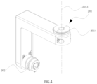
- shows a schematic diagram of the three-dimensional structure of the swivel (rotating) arm of the embodiment of
Fig. 1 ; - FIG. 5
- is a cross-sectional schematic view of the track lamp of the embodiment of
Fig. 1 ; and - Fig. 6
- shows a partial view of a detail of the track lamp of the embodiment of
Fig. 1 . - Throughout the drawings, the like reference numerals designate the same or technically equivalent members or groups of members.
- Specific embodiments of the present invention will be described in further detail below based on the accompanying drawings. It should be understood that the description of the embodiments of the present invention here is not intended to limit the protection scope of the present invention.
- As shown in
Figs. 1 to 6 , the track lamp of this embodiment comprises anadapter 100, aswivel arm 200 and alamp body 300. At the end close to theadapter 100, theswivel arm 200 comprises a firstrotating axis 201, which is divided into a first rotating half-axis 2011 and a second rotating half-axis 2012, which together define the firstrotating axis 201 and each extend along a direction perpendicular to the first rotatingcenterline 2013. The configuration and function of theadapter 100 andlamp body 300 is generally known from the prior art except for the part connected to theswivel arm 200, so that details thereof will not be described in the following. - In the
swivel arm 200 of the present embodiment, the first rotatingshaft 201 is arranged split along the direction of the first rotatingcenter line 2013, i.e. the first rotatingshaft 201 consists of two separate bearing shells connected to each other. This structure is more convenient to manufacture, because the first rotatingshaft 201 originally needs to be finished, and after being separated, the first rotating shaft can be directly formed by casting, thereby reducing the cost. - In this embodiment, the connection surfaces of the first rotating
half shaft 2011 and the second rotatinghalf shaft 2012 coincide with the first rotatingcenter line 2013. The first rotatinghalf shaft 2011 and the second rotatinghalf shaft 2012 can be fixedly connected by means of screws (as shown in the drawings) or by other fixed connection methods. - The
first rotation axis 201 is used for realizing a horizontal rotation of the track lamp, and maximum angle of the horizontal rotation can be limited by limiting protrusions, as generally known from prior art, so that there is no need to repeat details of this setting, and in this embodiment, maximum angle of the horizontal rotation may be set to 255 degrees. - In this embodiment, the first
rotating axis 201 is formed as a disc structure. The disc structure offers more contact surfaces, increasing the friction surface, and rotation connection with damping can be obtained if the opposite contact surfaces are tightly mated, thereby enabling a smoother hand feeling of the rotating movement, when horizontally rotating the track lamp. - Further, in this embodiment, the middle section of the disc structure is provided with an annular (ring-shaped)
clamping groove 2014, thereby increasing the contact surface with theadapter 100. - In this embodiment, the
adapter 100 includes aleft housing 101 and aright housing 102 split along the vertical first rotatingcenter line 2013. Theleft housing 101 and theright housing 102 are formed as separate members that are connected with each other to clamp the first rotatingshaft 201 properly and enable a tight-fit installation. The above structure is more convenient to manufacture and install. The inner shapes of theleft housing 101 andright housing 102 in the region accommodating and supporting the first rotatingshaft 201 correspond to the shape of the first rotatingshaft 201. In this embodiment, theleft housing 101 andright housing 102 are provided with grooves and faces adapted to the disc structure of the first rotatingshaft 201. Moreover, theleft housing 101 andright housing 102 are provided with annular clamping edges 103 inserted into theclamping grooves 2014 to clamp the first rotatingshaft 201. - In this embodiment, the
swivel arm 200 further comprises a second rotatingshaft 202 tightly fitted and connected to thelamp body 300. As shown inFig. 5 , thelamp body 300 comprises abase 301 for mounting the second rotatingshaft 202 and apressing block 302 for pressing the second rotatingshaft 202 against thebase 301 to adjust the friction at the second rotatingshaft 202. This structure is convenient to install and manufacture. Thepressing block 302 is semicircular and fixed by screws on both sides, and thebase 301 and thepressing block 302 are further provided with grooves for axially limiting the second rotatingshaft 202. Thebase 301 and thelamp body 300 can be made of the same material, generally of metal and particularly of a thin metal sheet. On the other hand, thepressing block 302 can be made of a plastic material that is highly resistant to abrasion, particularly of polyamide, so that the track lamp according to the present invention has good fatigue resistance and can rotate more smoothly. Polyamide can be used e.g. in a low-pressure molding process for manufacturing thepressing block 302 at high precision. - In this embodiment, the splicing or splitting direction of the first
rotating half shaft 2011 and the secondrotating half shaft 2012 is parallel to the centerline of the secondrotating shaft 202, that is, when the connecting surface of the firstrotating half shaft 2011 and the secondrotating half shaft 2012 is horizontal, the connecting surface is perpendicular to the centerline of the secondrotating shaft 202. - The second
rotating shaft 202 is used for realizing a vertical rotation of thelamp body 300, and is limited by arranging a protrusion, as is generally known from the prior art, so that details thereof need not be described here. In this embodiment, the maximum angle of the vertical rotation my be set to 220 degrees. - In this embodiment, the second
rotating shaft 202 formed at the end of theswivel arm 200 opposite to the firstrotating axis 201 comprises aninner shaft 2021 and anouter shaft 2022 sleeved or snapped on theinner shaft 2021, as shown inFig. 5 . As can be concluded fromFigs. 2 and3 , theswivel arm 200 is split into two halves (casings) and comprises aninner half arm 203 disposed close to thelamp body 300 and an outerhalf arm 204 remote from thelamp body 300. While the firstrotating half shaft 2011 and theouter shaft 2022 are integrally formed with the innerhalf arm 203, the secondrotating half shaft 2012 and theinner shaft 2021 are formed integrally with the outerhalf arm 204. Preferably, the outerhalf arm 203 is made of metal such as aluminum alloy, steel and the like, in particular of a thin metal sheet by punching and stamping, whereas the innerhalf arm 202 is made of a plastic material that is highly resistant to abrasion, such as polyamide, and can be manufactured by an injection molding process, in particular low-pressure molding process. Overall, this results in a rotational support of thelamp body 300 which has high reliability and good fatigue resistance, makes therotation arm 200 rotate more smoothly and stably, and can be manufactured at high precision at low costs. - With the above arrangement, a high mechanical strength and stability of the
swivel arm 200 can be ensured, and the manufacturing cost can be reduced. Preferably, theinner shaft 2021 is made of metal, such as aluminum alloy, steel and the like, in particular of a thin metal sheet by punching and stamping, whereas theouter shaft 2022 is made of a plastic material that is highly resistant to abrasion, such as polyamide, and can be manufactured by an injection molding process, in particular low-pressure molding process.. Overall, this enables a mechanical strength and stability of the secondrotating shaft 202, that can be manufactured at high precision at low costs, so that the rotation of thelamp body 300 can be smoother. - In this example, a
cavity 205 is provided between the two casing halves of theswivel arm 200, namely between theinner arm half 203 and theouter arm half 204, that can be used to guide a wire from theadapter 100 to thelamp body 300 for supplying electric power to a light emitting element or a power supply disposed in thelamp body 300. - In this embodiment, the
swivel arm 200 is L-shaped, which facilitates mounting thelamp body 300 stably. Moreover, thelamp body 300 includes ahousing 303, atop cover 304, apower source 305, aheat sink 306 and alight emitting element 307, such as an LED-array. Further details of thelamp body 300 need not be described as they are generally known from the prior art, and, of course, the swivel arm according to the present invention can be adopted also to other forms of track lamps. - The
adapter 100 is mated to a track (not shown in the drawings), that can be mounted on a horizontal mounting plane, such as a ceiling or a board of a shelf system, and can be moved along the track by sliding to an appropriate location for lighting and supplies electric power to the lamp. By means of theswivel arm 200 thelamp body 300 can be rotated about the firstrotating shaft 201 in a horizontal plane, which is in general parallel to the horizontal mounting plane, as well as about the secondrotating shaft 202 in a direction perpendicular to the horizontal mounting plane.
Claims (9)
- A track lamp comprising an adapter (100), a swivel arm (200) and a lamp body (300), whereinthe swivel arm (200) comprises a first rotating shaft (201) connected with the adapter (100) in a tight fit mode, andthe first rotating shaft (201) is divided into a first rotating half shaft (2011) and a second rotating half shaft (2012) along a direction of a first rotating center line (2013);whereinthe swivel arm (200) further comprises a second rotating shaft (202) tightly fitted to the lamp body (300), whereinthe second rotating shaft (202) comprises an inner shaft (202) and an outer shaft (2022) sleeved on the inner shaft (2021),the swivel arm (200) is split into two halves and comprises an inner half-arm (203) disposed close to the lamp body (400) and an outer half-arm (204) remote from the lamp body (300),the first rotating half shaft (2011) and the outer shaft (2022) are integrally formed with the inner half arm (203), andthe second rotating half shaft (2012) and the inner shaft (2021) are formed integrally with the outer half arm (204).
- The track lamp as claimed in claim 1, wherein the connection surfaces of the first rotating half shaft (2011) and the second rotating half shaft (2012) coincide with the first rotating center line (2013).
- The track lamp as claimed in claim 1 or 2, wherein the first rotating shaft (201) is formed as a disc structure.
- The track lamp as claimed in claim 3, wherein the disc structure is provided with a ring-shaped clamping groove (2014) in the middle section.
- The track lamp as claimed in any of the preceding claims, whereinthe adapter (100) comprises a left housing (101) and a right housing (102) joined along a direction perpendicular to the first rotation center line (2013), andthe left housing (101) and the right housing (102) together clamp the first rotating shaft (201) for a tight fit mounting.
- The track lamp as claimed in any of the preceding claims, wherein the lamp body (300) comprises a base (301) for supporting the second rotating shaft (202) and a pressing block (302) for pressing the second rotating shaft (202) against the base (301).
- The track lamp as claimed in any of the preceding claims, wherein the outer arm half (203) is made of metal, in particular of a thin metal sheet.
- The track lamp of claim 7, wherein the inner arm half (202) is formed of a plastic material that is highly resistant to abrasion, in particular of polyamide.
- The track lamp as claimed in any of the preceding claims, wherein a cavity (205) is provided between the inner half-arm (203) and the outer half-arm (204), for guiding a wire from the adapter (100) to the lamp body (300).
Applications Claiming Priority (1)
| Application Number | Priority Date | Filing Date | Title |
|---|---|---|---|
| CN202210023817.5A CN114484333A (en) | 2022-01-10 | 2022-01-10 | a track light |
Publications (2)
| Publication Number | Publication Date |
|---|---|
| EP4209707A1 EP4209707A1 (en) | 2023-07-12 |
| EP4209707B1 true EP4209707B1 (en) | 2025-04-23 |
Family
ID=81510446
Family Applications (1)
| Application Number | Title | Priority Date | Filing Date |
|---|---|---|---|
| EP22215025.2A Active EP4209707B1 (en) | 2022-01-10 | 2022-12-20 | Track lamp with swivel arm |
Country Status (2)
| Country | Link |
|---|---|
| EP (1) | EP4209707B1 (en) |
| CN (1) | CN114484333A (en) |
Family Cites Families (9)
| Publication number | Priority date | Publication date | Assignee | Title |
|---|---|---|---|---|
| GB8608900D0 (en) * | 1986-04-11 | 1986-05-14 | Light Source Electrical Equip | Low voltage distribution system |
| DE102005004246A1 (en) * | 2005-01-28 | 2006-08-10 | Erco Leuchten Gmbh | Device for fixing a lamp to a fixed space |
| DE202007004088U1 (en) * | 2007-03-20 | 2007-06-06 | Gies, Johannes | Lamp e.g. wall lamp, for use in e.g. camper, has head that is connected with telescopic tube via hinged part, where telescopic tube and support arm are connected with wall mounting via swivel device |
| CN203595039U (en) * | 2013-11-06 | 2014-05-14 | 深圳民爆光电技术有限公司 | LED track lamp |
| CN204943190U (en) * | 2015-08-17 | 2016-01-06 | 温州市登来特照明有限公司 | A kind of LED track lamp of ease of assembly |
| JP6729246B2 (en) * | 2016-09-27 | 2020-07-22 | 三菱電機株式会社 | lighting equipment |
| DE202018105238U1 (en) * | 2018-09-13 | 2019-12-16 | Zumtobel Lighting Gmbh | lamp |
| CN212081175U (en) * | 2020-04-03 | 2020-12-04 | 厦门高贤电子科技有限公司 | Track lamp connection structure |
| CN112283616A (en) * | 2020-10-22 | 2021-01-29 | 赛尔富电子有限公司 | A rotating arm structure of a lamp and a lamp with the rotating arm structure |
-
2022
- 2022-01-10 CN CN202210023817.5A patent/CN114484333A/en active Pending
- 2022-12-20 EP EP22215025.2A patent/EP4209707B1/en active Active
Also Published As
| Publication number | Publication date |
|---|---|
| CN114484333A (en) | 2022-05-13 |
| EP4209707A1 (en) | 2023-07-12 |
Similar Documents
| Publication | Publication Date | Title |
|---|---|---|
| US5289358A (en) | Recessed luminaire with a swivel housing | |
| US11391442B2 (en) | Polymer housing for a recessed lighting system and methods for using same | |
| US9593829B2 (en) | Hinge-mounted rotating base spotlight | |
| US7566223B2 (en) | Electrical connector and method of manufacturing same | |
| CA1297173C (en) | Low voltage distribution system with two-conductor track | |
| US5352122A (en) | Rotatable electrical connector | |
| US20110024593A1 (en) | Fixture support system and method | |
| US20210104856A1 (en) | Power distribution system | |
| US20160221184A1 (en) | Robot | |
| US5340322A (en) | Low voltage cable lighting system | |
| US20100294560A1 (en) | Mounting device for mounting electric components | |
| US2617619A (en) | Supporting arm for electrical fixtures | |
| CN101994946B (en) | Rotary desk lamp and rotating and positioning mechanism thereof | |
| EP4209707A1 (en) | Track lamp with swivel arm | |
| US5203626A (en) | Low voltage power distribution and lighting system | |
| US8684567B2 (en) | Lamp | |
| US11841118B1 (en) | Modular light bar assembly | |
| US4875648A (en) | Assembly comprising rolling means and slideways, and lighting apparatus comprising such an assembly | |
| US2826440A (en) | Combined swivel and pivot joint for electrical fixtures | |
| CN110332222B (en) | Ball head rotating device | |
| US11108300B2 (en) | Quick assembly structure used for driver | |
| CN212005341U (en) | Electric connecting base of track lamp | |
| CN220303555U (en) | Clip lamp | |
| CN215570301U (en) | Spliced lamp | |
| CN220793021U (en) | Line lamp with adjustable light angle |
Legal Events
| Date | Code | Title | Description |
|---|---|---|---|
| PUAI | Public reference made under article 153(3) epc to a published international application that has entered the european phase |
Free format text: ORIGINAL CODE: 0009012 |
|
| STAA | Information on the status of an ep patent application or granted ep patent |
Free format text: STATUS: THE APPLICATION HAS BEEN PUBLISHED |
|
| AK | Designated contracting states |
Kind code of ref document: A1 Designated state(s): AL AT BE BG CH CY CZ DE DK EE ES FI FR GB GR HR HU IE IS IT LI LT LU LV MC ME MK MT NL NO PL PT RO RS SE SI SK SM TR |
|
| STAA | Information on the status of an ep patent application or granted ep patent |
Free format text: STATUS: REQUEST FOR EXAMINATION WAS MADE |
|
| 17P | Request for examination filed |
Effective date: 20230916 |
|
| RBV | Designated contracting states (corrected) |
Designated state(s): AL AT BE BG CH CY CZ DE DK EE ES FI FR GB GR HR HU IE IS IT LI LT LU LV MC ME MK MT NL NO PL PT RO RS SE SI SK SM TR |
|
| GRAP | Despatch of communication of intention to grant a patent |
Free format text: ORIGINAL CODE: EPIDOSNIGR1 |
|
| STAA | Information on the status of an ep patent application or granted ep patent |
Free format text: STATUS: GRANT OF PATENT IS INTENDED |
|
| GRAS | Grant fee paid |
Free format text: ORIGINAL CODE: EPIDOSNIGR3 |
|
| INTG | Intention to grant announced |
Effective date: 20250212 |
|
| GRAA | (expected) grant |
Free format text: ORIGINAL CODE: 0009210 |
|
| STAA | Information on the status of an ep patent application or granted ep patent |
Free format text: STATUS: THE PATENT HAS BEEN GRANTED |
|
| AK | Designated contracting states |
Kind code of ref document: B1 Designated state(s): AL AT BE BG CH CY CZ DE DK EE ES FI FR GB GR HR HU IE IS IT LI LT LU LV MC ME MK MT NL NO PL PT RO RS SE SI SK SM TR |
|
| REG | Reference to a national code |
Ref country code: GB Ref legal event code: FG4D |
|
| REG | Reference to a national code |
Ref country code: CH Ref legal event code: EP |
|
| REG | Reference to a national code |
Ref country code: DE Ref legal event code: R096 Ref document number: 602022013509 Country of ref document: DE |
|
| REG | Reference to a national code |
Ref country code: IE Ref legal event code: FG4D |
|
| REG | Reference to a national code |
Ref country code: NL Ref legal event code: MP Effective date: 20250423 |
|
| PG25 | Lapsed in a contracting state [announced via postgrant information from national office to epo] |
Ref country code: NL Free format text: LAPSE BECAUSE OF FAILURE TO SUBMIT A TRANSLATION OF THE DESCRIPTION OR TO PAY THE FEE WITHIN THE PRESCRIBED TIME-LIMIT Effective date: 20250423 |
|
| REG | Reference to a national code |
Ref country code: AT Ref legal event code: MK05 Ref document number: 1788054 Country of ref document: AT Kind code of ref document: T Effective date: 20250423 |
|
| PG25 | Lapsed in a contracting state [announced via postgrant information from national office to epo] |
Ref country code: FI Free format text: LAPSE BECAUSE OF FAILURE TO SUBMIT A TRANSLATION OF THE DESCRIPTION OR TO PAY THE FEE WITHIN THE PRESCRIBED TIME-LIMIT Effective date: 20250423 Ref country code: ES Free format text: LAPSE BECAUSE OF FAILURE TO SUBMIT A TRANSLATION OF THE DESCRIPTION OR TO PAY THE FEE WITHIN THE PRESCRIBED TIME-LIMIT Effective date: 20250423 Ref country code: PT Free format text: LAPSE BECAUSE OF FAILURE TO SUBMIT A TRANSLATION OF THE DESCRIPTION OR TO PAY THE FEE WITHIN THE PRESCRIBED TIME-LIMIT Effective date: 20250825 |
|
| REG | Reference to a national code |
Ref country code: LT Ref legal event code: MG9D |
|
| PG25 | Lapsed in a contracting state [announced via postgrant information from national office to epo] |
Ref country code: GR Free format text: LAPSE BECAUSE OF FAILURE TO SUBMIT A TRANSLATION OF THE DESCRIPTION OR TO PAY THE FEE WITHIN THE PRESCRIBED TIME-LIMIT Effective date: 20250724 Ref country code: NO Free format text: LAPSE BECAUSE OF FAILURE TO SUBMIT A TRANSLATION OF THE DESCRIPTION OR TO PAY THE FEE WITHIN THE PRESCRIBED TIME-LIMIT Effective date: 20250723 |
|
| PG25 | Lapsed in a contracting state [announced via postgrant information from national office to epo] |
Ref country code: PL Free format text: LAPSE BECAUSE OF FAILURE TO SUBMIT A TRANSLATION OF THE DESCRIPTION OR TO PAY THE FEE WITHIN THE PRESCRIBED TIME-LIMIT Effective date: 20250423 |
|
| PG25 | Lapsed in a contracting state [announced via postgrant information from national office to epo] |
Ref country code: BG Free format text: LAPSE BECAUSE OF FAILURE TO SUBMIT A TRANSLATION OF THE DESCRIPTION OR TO PAY THE FEE WITHIN THE PRESCRIBED TIME-LIMIT Effective date: 20250423 |
|
| PG25 | Lapsed in a contracting state [announced via postgrant information from national office to epo] |
Ref country code: HR Free format text: LAPSE BECAUSE OF FAILURE TO SUBMIT A TRANSLATION OF THE DESCRIPTION OR TO PAY THE FEE WITHIN THE PRESCRIBED TIME-LIMIT Effective date: 20250423 |
|
| PG25 | Lapsed in a contracting state [announced via postgrant information from national office to epo] |
Ref country code: AT Free format text: LAPSE BECAUSE OF FAILURE TO SUBMIT A TRANSLATION OF THE DESCRIPTION OR TO PAY THE FEE WITHIN THE PRESCRIBED TIME-LIMIT Effective date: 20250423 |
|
| PG25 | Lapsed in a contracting state [announced via postgrant information from national office to epo] |
Ref country code: RS Free format text: LAPSE BECAUSE OF FAILURE TO SUBMIT A TRANSLATION OF THE DESCRIPTION OR TO PAY THE FEE WITHIN THE PRESCRIBED TIME-LIMIT Effective date: 20250723 |
|
| PG25 | Lapsed in a contracting state [announced via postgrant information from national office to epo] |
Ref country code: IS Free format text: LAPSE BECAUSE OF FAILURE TO SUBMIT A TRANSLATION OF THE DESCRIPTION OR TO PAY THE FEE WITHIN THE PRESCRIBED TIME-LIMIT Effective date: 20250823 |
|
| PG25 | Lapsed in a contracting state [announced via postgrant information from national office to epo] |
Ref country code: LV Free format text: LAPSE BECAUSE OF FAILURE TO SUBMIT A TRANSLATION OF THE DESCRIPTION OR TO PAY THE FEE WITHIN THE PRESCRIBED TIME-LIMIT Effective date: 20250423 |
|
| PG25 | Lapsed in a contracting state [announced via postgrant information from national office to epo] |
Ref country code: DK Free format text: LAPSE BECAUSE OF FAILURE TO SUBMIT A TRANSLATION OF THE DESCRIPTION OR TO PAY THE FEE WITHIN THE PRESCRIBED TIME-LIMIT Effective date: 20250423 Ref country code: SM Free format text: LAPSE BECAUSE OF FAILURE TO SUBMIT A TRANSLATION OF THE DESCRIPTION OR TO PAY THE FEE WITHIN THE PRESCRIBED TIME-LIMIT Effective date: 20250423 |
|
| PG25 | Lapsed in a contracting state [announced via postgrant information from national office to epo] |
Ref country code: CZ Free format text: LAPSE BECAUSE OF FAILURE TO SUBMIT A TRANSLATION OF THE DESCRIPTION OR TO PAY THE FEE WITHIN THE PRESCRIBED TIME-LIMIT Effective date: 20250423 |
|
| PG25 | Lapsed in a contracting state [announced via postgrant information from national office to epo] |
Ref country code: EE Free format text: LAPSE BECAUSE OF FAILURE TO SUBMIT A TRANSLATION OF THE DESCRIPTION OR TO PAY THE FEE WITHIN THE PRESCRIBED TIME-LIMIT Effective date: 20250423 |
|
| REG | Reference to a national code |
Ref country code: DE Ref legal event code: R097 Ref document number: 602022013509 Country of ref document: DE |
|
| PG25 | Lapsed in a contracting state [announced via postgrant information from national office to epo] |
Ref country code: SK Free format text: LAPSE BECAUSE OF FAILURE TO SUBMIT A TRANSLATION OF THE DESCRIPTION OR TO PAY THE FEE WITHIN THE PRESCRIBED TIME-LIMIT Effective date: 20250423 |
|
| PG25 | Lapsed in a contracting state [announced via postgrant information from national office to epo] |
Ref country code: IT Free format text: LAPSE BECAUSE OF FAILURE TO SUBMIT A TRANSLATION OF THE DESCRIPTION OR TO PAY THE FEE WITHIN THE PRESCRIBED TIME-LIMIT Effective date: 20250423 |
|
| PLBE | No opposition filed within time limit |
Free format text: ORIGINAL CODE: 0009261 |
|
| STAA | Information on the status of an ep patent application or granted ep patent |
Free format text: STATUS: NO OPPOSITION FILED WITHIN TIME LIMIT |
|
| REG | Reference to a national code |
Ref country code: CH Ref legal event code: L10 Free format text: ST27 STATUS EVENT CODE: U-0-0-L10-L00 (AS PROVIDED BY THE NATIONAL OFFICE) Effective date: 20260304 |
|
| PG25 | Lapsed in a contracting state [announced via postgrant information from national office to epo] |
Ref country code: RO Free format text: LAPSE BECAUSE OF FAILURE TO SUBMIT A TRANSLATION OF THE DESCRIPTION OR TO PAY THE FEE WITHIN THE PRESCRIBED TIME-LIMIT Effective date: 20250423 |
|
| 26N | No opposition filed |
Effective date: 20260126 |
|
| PGFP | Annual fee paid to national office [announced via postgrant information from national office to epo] |
Ref country code: DE Payment date: 20251219 Year of fee payment: 4 |