EP4209697A1 - A cable tie arrangement - Google Patents
A cable tie arrangement Download PDFInfo
- Publication number
- EP4209697A1 EP4209697A1 EP22215853.7A EP22215853A EP4209697A1 EP 4209697 A1 EP4209697 A1 EP 4209697A1 EP 22215853 A EP22215853 A EP 22215853A EP 4209697 A1 EP4209697 A1 EP 4209697A1
- Authority
- EP
- European Patent Office
- Prior art keywords
- strap
- opening
- cable tie
- section
- locking head
- Prior art date
- Legal status (The legal status is an assumption and is not a legal conclusion. Google has not performed a legal analysis and makes no representation as to the accuracy of the status listed.)
- Granted
Links
Images



Classifications
-
- B—PERFORMING OPERATIONS; TRANSPORTING
- B65—CONVEYING; PACKING; STORING; HANDLING THIN OR FILAMENTARY MATERIAL
- B65D—CONTAINERS FOR STORAGE OR TRANSPORT OF ARTICLES OR MATERIALS, e.g. BAGS, BARRELS, BOTTLES, BOXES, CANS, CARTONS, CRATES, DRUMS, JARS, TANKS, HOPPERS, FORWARDING CONTAINERS; ACCESSORIES, CLOSURES, OR FITTINGS THEREFOR; PACKAGING ELEMENTS; PACKAGES
- B65D63/00—Flexible elongated elements, e.g. straps, for bundling or supporting articles
-
- F—MECHANICAL ENGINEERING; LIGHTING; HEATING; WEAPONS; BLASTING
- F16—ENGINEERING ELEMENTS AND UNITS; GENERAL MEASURES FOR PRODUCING AND MAINTAINING EFFECTIVE FUNCTIONING OF MACHINES OR INSTALLATIONS; THERMAL INSULATION IN GENERAL
- F16L—PIPES; JOINTS OR FITTINGS FOR PIPES; SUPPORTS FOR PIPES, CABLES OR PROTECTIVE TUBING; MEANS FOR THERMAL INSULATION IN GENERAL
- F16L3/00—Supports for pipes, cables or protective tubing, e.g. hangers, holders, clamps, cleats, clips, brackets
- F16L3/22—Supports for pipes, cables or protective tubing, e.g. hangers, holders, clamps, cleats, clips, brackets specially adapted for supporting a number of parallel pipes at intervals
- F16L3/23—Supports for pipes, cables or protective tubing, e.g. hangers, holders, clamps, cleats, clips, brackets specially adapted for supporting a number of parallel pipes at intervals for a bundle of pipes or a plurality of pipes placed side by side in contact with each other
- F16L3/233—Supports for pipes, cables or protective tubing, e.g. hangers, holders, clamps, cleats, clips, brackets specially adapted for supporting a number of parallel pipes at intervals for a bundle of pipes or a plurality of pipes placed side by side in contact with each other by means of a flexible band
- F16L3/2338—Supports for pipes, cables or protective tubing, e.g. hangers, holders, clamps, cleats, clips, brackets specially adapted for supporting a number of parallel pipes at intervals for a bundle of pipes or a plurality of pipes placed side by side in contact with each other by means of a flexible band having at least one metal locking barb
-
- B—PERFORMING OPERATIONS; TRANSPORTING
- B65—CONVEYING; PACKING; STORING; HANDLING THIN OR FILAMENTARY MATERIAL
- B65D—CONTAINERS FOR STORAGE OR TRANSPORT OF ARTICLES OR MATERIALS, e.g. BAGS, BARRELS, BOTTLES, BOXES, CANS, CARTONS, CRATES, DRUMS, JARS, TANKS, HOPPERS, FORWARDING CONTAINERS; ACCESSORIES, CLOSURES, OR FITTINGS THEREFOR; PACKAGING ELEMENTS; PACKAGES
- B65D63/00—Flexible elongated elements, e.g. straps, for bundling or supporting articles
- B65D63/10—Non-metallic straps, tapes, or bands; Filamentary elements, e.g. strings, threads or wires; Joints between ends thereof
- B65D63/14—Joints produced by application of separate securing members
Definitions
- This invention relates to a cable tie arrangement. More specifically, although not exclusively, this invention relates to a cable tie arrangement for bundling a plurality of elongate elements, such as wires, cables, tubes, pipes and similar.
- Prior art cable tie arrangements have a periodic arrangement of raised elements which extend along the length of a strap. These raised elements engage an extension in a locking head to bundle cables or similar in a ratchetting manner. However, as the tension in the strap is determined by the spacing between the raised elements this results in poor or loose bundling.
- the present invention seeks to address at least some of these issues.
- a cable tie arrangement for bundling one or more elongate members comprising:
- the planar surface has a raised central portion.
- the strap comprises a second raised central portion on an opposed side of the strap to the first raised central portion.
- the opposed teeth are arranged to engage the raised central portion.
- the continuous strap comprises a second planar surface opposed the first planar surface.
- the second planar surface is arranged substantially the same as the first planar surface.
- the locking head comprises one or more shoulders for guiding the continuous strap through the opening.
- the metal locking element circumscribes the opening.
- the locking head comprises inter-engaging elements for engaging with a further corresponding locking head.
- the strap has a thickness and the opposed teeth define a gap extending perpendicularly therebetween, and wherein the gap is substantially twice the thickness of the strap.
- a locking head for use in a cable tie arrangement according to any preceding claim, the locking head comprising:
- a magazine comprising a plurality of locking heads according to the first aspect.
- a reel of continuous strap for use in a cable tie arrangement according to the first aspect.
- the described example embodiment relates to cable ties used for bunding a plurality of component, such as, cables, wires, conduits and the like.
- the terms 'connected', 'attached', 'coupled', 'mounted' are intended to include direct connections between two members without any other members interposed therebetween, as well as, indirect connections between members in which one or more other members are interposed therebetween.
- the terminology includes the words specifically mentioned above, derivatives thereof, and words of similar import.
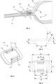
- FIGS 1 & 2 illustrate an exemplary cable tie arrangement 10 with two elongate elements 1A, 1B, for example, wires, cables, tubes, pipes or similar.
- the illustrated cable tie arrangement 10 includes a locking head 100 and a section of a continuous strap 50 looped around the elongate elements 1A, 1B.
- the continuous strap 50 includes a supply section 52 which passes through an opening 105 of the locking head 100.
- the supply section 52 is fed from a supply 'S' of strap material, for example, a reel 30 of strap material as shown in Figure 10 .
- the continuous strap 50 also includes a looped section 54 which circumscribes the elongate elements 1A, 1B to bundle the elongate elements 1A, 1B on one side of the locking head 100, and an end section 56 which passes through the opening 105 in the locking head 100.
- the supply section 52, the looped section 54 and the end section 56 are shown as forming a continuum from one section to the other section. As shown in Figure 2 , the supply section 52 passes from a first side of a plane 'P' defined by the locking head 100 to a second side of the locking head 100 in a first direction A1 (see Figure 6 ), and the end section 56 passes from the second side of the plane to the first side through the locking head 100 in a second direction opposed to the first direction A1.
- Figure 3 is a perspective view of the cable tie arrangement of Figure 2 with parts of the locking head 100 omitted.
- a locking element 110 is provided in the locking head 100 that is designed to restrict relative movement between the supply section 52 and the end section 56 within the opening 105 of the locking head 100 in order to securely bundle the plurality of elongate members 1A, 1B.
- the illustrated locking element 110 comprises metal, but it would be apparent that this was not essential, and that in other cases, the locking element 110 may contain other materials in addition to, or as an alternative to metal.
- the locking head 100 includes a body in which the locking element 110 is inserted.
- the body of the locking head 100 defines the opening 105 and the locking element 110 includes a body 112 designed to circumscribe the opening 105 in the locking head 100.
- the locking element 110 includes a pair of teeth 115 designed to engage the supply section 52 and the end section 56.
- the teeth 115 grip or bite into a smooth planar surface of the strap 50.
- the planar surface of the strap 50 may extend across the entire width of the strap 50 or a portion of the strap 50 as will be explained below. While the teeth 115 are shown extending across partially across the width of the strap 50, it would be apparent that the teeth 115 may extend across the entire width of the strap 50.
- teeth should be understood as meaning free of protrusions, racks or similar elements which are raised from the surface of the strap 50.
- An advantage of the present invention is a smooth strap allows for better bundling of elongate elements 1A, 1B, as the strap 50 can be tightened optimally based on the overall cross-section of the elongate elements 1A, 1B and by the teeth 115 biting into the planar surface. This is in contrast to prior art straps, where extensions engage the raised protrusions or racks of a strap, rather than the main surface of the strap which results in poor or loose bundling.
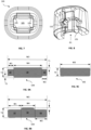
- Figure 5 shows a side view of the locking element 110.
- the locking element 110 is formed of a plate having a thickness X1, an overall width X5 (taken as the horizontal distance in the orientation shown in Figure 6 ) and an overall height X4 (taken as the vertical distance in the orientation shown in Figure 6 ).
- the teeth 115 extend at an acute angle relative to a plane defined by the body 112 of the locking 110.
- the example locking element 100 shown in Figure 5 has the teeth 115 extending at an angle A1 relative to an axis normal to the plane of the body 112.
- a gap X3 is formed between the free ends of the teeth 115, and the space between the base of the teeth 115, the base being where the teeth 115 connect to the body 112, is at a distance X6.
- the teeth 115 have a width X7 and protrude from the body 112 by 0.7mm (taken as the difference between X2 and X1).
- the body 112 forms an annulus around the opening 105 and has a first inner width X8 and a second inner width X9.
- the different inner widths X8, X9 of the body 112 help to accommodate the strap 50, particularly, where the strap 50 has one or more peripheral portions 60 (see Figure 9 ) as will be explained below.
- the dimensions provided are merely examples of suitable dimensions for a strap 50 having corresponding dimensions.
- a similar locking element 110 could be designed with variations on these dimensions either with respect to the absolute values provided herein, or the ratios between the values provided herein.
- the teeth 115 have a face 117 which is substantially perpendicular to an insertion direction D1 of the strap 50 (see Figure 8 ).
- An edge of each tooth 115 which defines the face 117 can be considered to form a blade which engages the surface of the strap 50 and grips the strap 50 when inserted into the locking head 100.
- the locking head 100 body can also include shoulders 120 to guide either or both of the supply section 52 and the end section 56 of the strap through the opening 105. While four shoulders 120 are shown, it would be apparent that this was merely exemplary and that one or more shoulders 120 could be provided to achieve the same function. While the shoulders 120 are shown at opposed corners of the opening 105 it would be apparent that this was not essential and that other arrangements would be suitable for guiding the strap 50.
- Figure 8 is a cross-sectional view of the locking head 100 of Figure 5 .
- the locking element 110 is shown inserted in the body of the locking head 110 and the teeth 115 are angled to allow the strap 50, or a section 52, 56 thereof, to pass in a first direction D1, but not in a second direction opposed to D1.
- the teeth 115 of the locking element 110 extend into the opening 105 and have a curved base section which extends from a substantially perpendicular angle relative to the first direction D1, to an acute angle relative to the first direction.
- a buttress or supporting portion 125 of the body of the locking head 110 is also shown in Figure 8 .
- each tooth 115 This helps to resist motion of the strap sections 52, 56 in the second direction by abutting the teeth 115, thereby stiffening the teeth 115 and increasing the resistance of the locking head 110 to motion of the strap sections 52, 56 in the second direction.
- a single solid supporting portion 125 is provided for each tooth 115, it would be apparent this was not essential and the supporting portion 125 may be formed of a plurality of supporting portions 125. Similarly, the supporting portion 125 may only extend partially along the length of each tooth 115. For example, supporting the base section entirely and only supporting a part of the remaining tooth 115 as shown in Figure 8 .
- FIGS 9A to 9C illustrate a cross-sectional view of different exemplary straps 50A, 50B, 50C.
- the strap 50A has a substantially rectangular cross-section defining an overall width W3 and thickness T3.
- the overall thickness of the strap 50A T3 is approximately 1.0mm and the overall width W3 is approximately 4.5mm.
- An alternative exemplary strap may have an overall width W3 of approximately 7.5mm and an overall thickness T3 of approximately 1.5mm.
- the gap X3 between the teeth 115 corresponds to twice the thickness T3 of strap 50A, as the supply section 52 and the end section 56 overlap in the opening 105.
- the gap X3 may be between one and two times the thickness T3 of the strap 50A, as this may provide a more robust grip on the ends 52, 56 of the strap in the opening 105 as the teeth 115 are deformed by the sections of strap 50A passing therebetween. It would be apparent that the gap X3 would be greater than the strap 50A thickness T3.
- the strap 50A is also shown having a raised central portion 58 which provides the planar surface against which the teeth 115 can engage the strap sections 52, 56.
- the teeth 115 extend across substantially the width of the raised central portion 58. In some cases, the teeth 115 may also extend across a part of the whole of the peripheral portion 60. Peripheral portions 60 are adjacent the central portion 58 and extend substantially along the length of the strap 50A.
- the peripheral portions help to align the central portion 58 within the opening 105 and facilitate good engagement between the teeth 115 and the central portion 58.
- the raised central portion 58 has a width W4 that is greater than or equal to half the width X7 of the tooth 115.
- the raised section may have a width of 2mm.
- each of the peripheral portions 60 has a width W1, W2.
- the central portion 58 is raised relative to the peripheral portion 60 on a first side by a distance T1 and a second side by a distance T2. It would be apparent that the peripheral portions 60 do not need to have the same dimensions and that T1 and T2 may be different to one another, and that W1 and W2 may be different to one another.
- the opening 105 is designed to accommodate the peripheral portions 60 between the shoulders 120. In some cases, only the raised central portion 58 engages the teeth 115. It would be apparent that the raised central portion 58 may only be raised on a single side of the strap 50A, such as shown in Figure 9B . As the strap 50A is looped back on itself such that the supply section 52 and end section 56 overlap and abut one another in the opening 105, the abutting sides of the supply section 52 and end section 56 need not have a raised section 58. In some cases, the strap 50A may have a uniform cross section, such that there is no raised central portion 58.
- FIG 9B illustrates an alternative exemplary strap 50B having a raised section 58 only on a single side of the strap 50B.
- the raised section 58 is narrower than that illustrated in strap 50A.
- the raised section 58 of strap 50B is less than or equal to half of the width X7 of the tooth 115.
- Strap 50A may include a similarly narrow raised section 58.
- Figure 9C illustrates a further exemplary strap 50C having no raised portions. Strap 50C has a substantially rectangular cross-sectional profile.
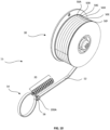
- FIG 10 is a perspective view of an exemplary cable tie assembly 15.
- the cable tie assembly 15 includes a reel 30 with six continuous straps 50A-50F shown mounted thereto. Each strap 50A-50F may have any of the features described above in relation to the strap of Figure 9 .
- a continuous strap 50 enables the looped section 54 to have any length, and thus allows for a greater range of elongate members 1A, 1B to be bundled.
- the assembly 15 also includes a magazine 20 of locking heads, and a single "active" locking head 200A through which a supply section 52 and an end section 56 of one of the straps 50A - 50F extends in the manner described above.
- the elongate members 1A, 1B have been omitted from the looped section 54 for clarity.
- locking head 100 may be used in the cable tie assembly 15 in the same manner as locking head 200.
- FIGs 11A & 11B are perspective views of an alternative locking head 200.
- the locking head 200 has an opening 205 and a locking element 210 which function in a similar manner as opening 105 and locking element 110 described above.
- the locking element 110 circumscribes the opening 205 and teeth 215 extend from the body 212 into the opening 205 to grip the strap sections 52, 56 that pass through the opening 205 so that the sections 52, 56 can be pulled through the opening 205 in a first direction but are resisted from being pulled through the opening 205 in the opposite direction.
- a supporting portion 235 is also provided which functions in a similar manner to supporting portion 125 described above.
- the locking head 200 is also shown having a pair of tabs 225 and a pair of protrusions 220 which engage corresponding tabs 225 and protrusions 220 on an adjacent locking head 200. While the tabs 225 and protrusions 220 are formed on the same sides of the locking heads 200 from which the teeth 115 extend (i.e. the upper and lower sides as shown in Figure 14 ), it would be apparent this was not essential and that the protrusions 220 and tabs 225 may be formed on different sides to those from which the teeth 115 extend. It would also be apparent that the tabs 225 and protrusions 220 were merely one example of suitable inter-engaging mechanical elements that allow one locking head 200 to be releasably connected to a second locking head 200.
- Locking heads 200A - 200C are all formed substantially identically to one another and are connected to one another via the protrusions 220 and tabs 225. As shown in Figures 14 and 15 , each tab 225 has a recess 230 formed therein for receiving the protrusion 220 of an adjacent locking head 200.
- the magazine 20 can then be loaded in a cable tie tool, and as the next locking head 200 is required, a locking head on the end of the magazine 20 can be easily separated from the remaining locking heads 200 to become the "active" locking head 200A for the strap 50 to be drawn through in the manner described above.
Landscapes
- Engineering & Computer Science (AREA)
- Mechanical Engineering (AREA)
- General Engineering & Computer Science (AREA)
- Package Frames And Binding Bands (AREA)
Abstract
Description
- This invention relates to a cable tie arrangement. More specifically, although not exclusively, this invention relates to a cable tie arrangement for bundling a plurality of elongate elements, such as wires, cables, tubes, pipes and similar.
- Prior art cable tie arrangements have a periodic arrangement of raised elements which extend along the length of a strap. These raised elements engage an extension in a locking head to bundle cables or similar in a ratchetting manner. However, as the tension in the strap is determined by the spacing between the raised elements this results in poor or loose bundling.
- The present invention seeks to address at least some of these issues.
- Aspects of the invention are set out in the independent claim(s). Dependent claims describe optional features.
- According to a first aspect of the invention, there is provided a cable tie arrangement for bundling one or more elongate members, the cable tie arrangement comprising:
- a continuous strap having a planar surface free of any racks, and
- a separate locking head defining an opening and having a metal locking element comprising a pair of opposed teeth extending into the opening and arranged to engage the strap in the opening, and
- wherein, in use, the continuous strap comprises a looped section arranged to bundle one or more elongate elements on a first side of the locking head, and the looped section has an end section and a supply section extending through the locking head to a second side of the locking head in a first direction,
- wherein the opposed teeth are arranged to engage the planar surface of the end section and the supply section to prevent movement of the end section and the supply section in a second direction opposed to the first direction and to allow movement of the supply section in the first direction, and
- wherein the opposed teeth extend towards one another in the opening, so as to press the end section and the supply section together in the opening.
- Advantageously, the planar surface has a raised central portion. Preferably, the strap comprises a second raised central portion on an opposed side of the strap to the first raised central portion.
- Advantageously, the opposed teeth are arranged to engage the raised central portion.
- Advantageously, the continuous strap comprises a second planar surface opposed the first planar surface. Preferably, the second planar surface is arranged substantially the same as the first planar surface.
- Advantageously, the locking head comprises one or more shoulders for guiding the continuous strap through the opening.
- Advantageously, the metal locking element circumscribes the opening.
- Advantageously, the locking head comprises inter-engaging elements for engaging with a further corresponding locking head.
- Advantageously, the strap has a thickness and the opposed teeth define a gap extending perpendicularly therebetween, and wherein the gap is substantially twice the thickness of the strap.
- According to a further aspect of the present invention, there is provided a locking head for use in a cable tie arrangement according to any preceding claim, the locking head comprising:
- an opening, and a metal locking element comprising a pair of opposed teeth extending into the opening and arranged to engage a strap in the opening,
- wherein the opposed teeth are arranged to engage a planar surface of an end section and a supply section of the strap to prevent movement of the end section and the supply section in a second direction opposed to the first direction and to allow movement of the supply section in the first direction, and
- wherein the opposed teeth extend towards one another in the opening so as to press the end section and the supply section together in the opening.
- A magazine comprising a plurality of locking heads according to the first aspect.
- A reel of continuous strap for use in a cable tie arrangement according to the first aspect.
- Embodiments of the invention are further described hereinafter with reference to the accompanying drawings, in which:
-
Figure 1 illustrates an exemplary cable tie arrangement with two elongate elements in a perspective view; -
Figure 2 illustrate the exemplary cable tie arrangement with two elongate elements ofFigure 1 in a top view; -
Figure 3 is a perspective view of the cable tie arrangement ofFigure 2 with parts of a locking head omitted (schematic); -
Figure 4 illustrates an exemplary metal locking element of the locking head in a perspective view; -
Figure 5 illustrates the locking element ofFigure 4 in a side view; -
Figure 6 illustrates the locking element ofFigure 4 in a top view (plan view); -
Figure 7 illustrates the locking head of the cable tie arrangement ofFigure 1 in a perspective view; -
Figure 8 shows a cross-sectional perspective view of the locking head ofFigure 7 (transparent); -
Figure 9 A-C shows cross-sectional views of different exemplary straps; -
Figure 10 is a perspective view of an exemplary cable tie assembly rolled up in a magazine of a tool, with an array of locking heads as provided with the tool; -
Figure 11 A,B are perspective views of an alternative locking head; -
Figure 12 A,B are respective cross-sectional views of the locking head ofFigure 11 ; -
Figure 13 is a perspective view of an exemplary array of locking heads as provided within a tool magazine; -
Figure 14 is a side view of the array ofFigure 13 with some locking heads omitted, and -
Figure 15 shows the array ofFigure 13 with a cross-sectional view of the front locking head. - The described example embodiment relates to cable ties used for bunding a plurality of component, such as, cables, wires, conduits and the like.
- Certain terminology may be used in the following description for convenience only and is not limiting. The words 'right', 'left', 'lower', 'upper', 'front', 'rear', 'upward', 'down', 'downward', 'above' and 'below' designate directions in the drawings to which reference is made and are with respect to the described component when assembled and mounted (e.g. in situ). The words 'inner', 'inwardly' and 'outer', 'outwardly' refer to directions toward and away from, respectively, a designated centreline or a geometric centre of an element being described (e.g. central axis), the particular meaning being readily apparent from the context of the description.
- Further, as used herein, the terms 'connected', 'attached', 'coupled', 'mounted' are intended to include direct connections between two members without any other members interposed therebetween, as well as, indirect connections between members in which one or more other members are interposed therebetween. The terminology includes the words specifically mentioned above, derivatives thereof, and words of similar import.
- Further, unless otherwise specified, the use of ordinal adjectives, such as, 'first', 'second', 'third' etc. merely indicate that different instances of like objects are being referred to and are not intended to imply that the objects so described must be in a given sequence, either temporally, spatially, in ranking or in any other manner.
- Through the description and claims of this specification, the terms 'comprise' and 'contain', and variations thereof, are interpreted to mean 'including but not limited to', and they are not intended to (and do not) exclude other moieties, additives, components, integers or steps. Throughout the description and claims of this specification, the singular encompasses the plural unless the context otherwise requires. In particular, where the indefinite article is used, the specification is to be understood as contemplating plurality, as well as, singularity, unless the context requires otherwise.
- Features, integers, characteristics, compounds, chemical moieties or groups described in conjunction with a particular aspect, embodiment or example of the invention are to be understood to be applicable to any other aspect, embodiment or example described herein unless incompatible therewith. All of the features disclosed in this specification (including any accompanying claims, abstract and drawings), and/or all of the steps of any method or process so disclosed, may be combined in any combination, except combinations where at least some of such features and/or steps are mutually exclusive. The invention is not restricted to the details of any foregoing embodiments. The invention extends to any novel one, or any novel combination, of the features disclosed in this specification (including any accompanying claims, abstract or drawings), or to any novel one, or any novel combination, of the steps of any method or process so disclosed.
-
Figures 1 & 2 illustrate an exemplarycable tie arrangement 10 with twoelongate elements cable tie arrangement 10 includes alocking head 100 and a section of acontinuous strap 50 looped around theelongate elements continuous strap 50 includes asupply section 52 which passes through anopening 105 of the lockinghead 100. In some cases, thesupply section 52 is fed from a supply 'S' of strap material, for example, areel 30 of strap material as shown inFigure 10 . Thecontinuous strap 50 also includes a loopedsection 54 which circumscribes theelongate elements elongate elements head 100, and anend section 56 which passes through theopening 105 in the lockinghead 100. Thesupply section 52, the loopedsection 54 and theend section 56 are shown as forming a continuum from one section to the other section. As shown inFigure 2 , thesupply section 52 passes from a first side of a plane 'P' defined by the lockinghead 100 to a second side of the lockinghead 100 in a first direction A1 (seeFigure 6 ), and theend section 56 passes from the second side of the plane to the first side through the lockinghead 100 in a second direction opposed to the first direction A1. -
Figure 3 is a perspective view of the cable tie arrangement ofFigure 2 with parts of the lockinghead 100 omitted. - With reference to
Figure 4 , alocking element 110 is provided in the lockinghead 100 that is designed to restrict relative movement between thesupply section 52 and theend section 56 within theopening 105 of the lockinghead 100 in order to securely bundle the plurality ofelongate members locking element 110 comprises metal, but it would be apparent that this was not essential, and that in other cases, the lockingelement 110 may contain other materials in addition to, or as an alternative to metal. The lockinghead 100 includes a body in which thelocking element 110 is inserted. The body of the lockinghead 100 defines theopening 105 and thelocking element 110 includes abody 112 designed to circumscribe theopening 105 in the lockinghead 100. While theopening 105 is shown as substantially rectangular and the overlappingsupply section 52 andend section 56 have a corresponding cross-section, it would be apparent that this was not essential. In some cases, theopening 105 can have other cross-sections which correspond to the cross-section of thestrap 50. The lockingelement 110 includes a pair ofteeth 115 designed to engage thesupply section 52 and theend section 56. In particular, theteeth 115 grip or bite into a smooth planar surface of thestrap 50. The planar surface of thestrap 50 may extend across the entire width of thestrap 50 or a portion of thestrap 50 as will be explained below. While theteeth 115 are shown extending across partially across the width of thestrap 50, it would be apparent that theteeth 115 may extend across the entire width of thestrap 50. The term "smooth" should be understood as meaning free of protrusions, racks or similar elements which are raised from the surface of thestrap 50. An advantage of the present invention is a smooth strap allows for better bundling ofelongate elements strap 50 can be tightened optimally based on the overall cross-section of theelongate elements teeth 115 biting into the planar surface. This is in contrast to prior art straps, where extensions engage the raised protrusions or racks of a strap, rather than the main surface of the strap which results in poor or loose bundling. -
Figure 5 shows a side view of thelocking element 110. With reference toFigures 5 and 6 , the lockingelement 110 is formed of a plate having a thickness X1, an overall width X5 (taken as the horizontal distance in the orientation shown inFigure 6 ) and an overall height X4 (taken as the vertical distance in the orientation shown inFigure 6 ). Theteeth 115 extend at an acute angle relative to a plane defined by thebody 112 of the locking 110. Theexample locking element 100 shown inFigure 5 has theteeth 115 extending at an angle A1 relative to an axis normal to the plane of thebody 112. A gap X3 is formed between the free ends of theteeth 115, and the space between the base of theteeth 115, the base being where theteeth 115 connect to thebody 112, is at a distance X6. Theteeth 115 have a width X7 and protrude from thebody 112 by 0.7mm (taken as the difference between X2 and X1). Thebody 112 forms an annulus around theopening 105 and has a first inner width X8 and a second inner width X9. The different inner widths X8, X9 of thebody 112 help to accommodate thestrap 50, particularly, where thestrap 50 has one or more peripheral portions 60 (seeFigure 9 ) as will be explained below. It would be apparent that the dimensions provided are merely examples of suitable dimensions for astrap 50 having corresponding dimensions. Asimilar locking element 110 could be designed with variations on these dimensions either with respect to the absolute values provided herein, or the ratios between the values provided herein. As shown inFigures 4 and 5 , theteeth 115 have aface 117 which is substantially perpendicular to an insertion direction D1 of the strap 50 (seeFigure 8 ). An edge of eachtooth 115 which defines theface 117 can be considered to form a blade which engages the surface of thestrap 50 and grips thestrap 50 when inserted into the lockinghead 100. - As shown in
Figure 7 the lockinghead 100 body can also includeshoulders 120 to guide either or both of thesupply section 52 and theend section 56 of the strap through theopening 105. While fourshoulders 120 are shown, it would be apparent that this was merely exemplary and that one ormore shoulders 120 could be provided to achieve the same function. While theshoulders 120 are shown at opposed corners of theopening 105 it would be apparent that this was not essential and that other arrangements would be suitable for guiding thestrap 50. -
Figure 8 is a cross-sectional view of the lockinghead 100 ofFigure 5 . The lockingelement 110 is shown inserted in the body of the lockinghead 110 and theteeth 115 are angled to allow thestrap 50, or asection teeth 115 of thelocking element 110 extend into theopening 105 and have a curved base section which extends from a substantially perpendicular angle relative to the first direction D1, to an acute angle relative to the first direction. A buttress or supportingportion 125 of the body of the lockinghead 110 is also shown inFigure 8 . This helps to resist motion of thestrap sections teeth 115, thereby stiffening theteeth 115 and increasing the resistance of the lockinghead 110 to motion of thestrap sections portion 125 is provided for eachtooth 115, it would be apparent this was not essential and the supportingportion 125 may be formed of a plurality of supportingportions 125. Similarly, the supportingportion 125 may only extend partially along the length of eachtooth 115. For example, supporting the base section entirely and only supporting a part of the remainingtooth 115 as shown inFigure 8 . -
Figures 9A to 9C illustrate a cross-sectional view of differentexemplary straps Figure 9A , thestrap 50A has a substantially rectangular cross-section defining an overall width W3 and thickness T3. The overall thickness of thestrap 50A T3 is approximately 1.0mm and the overall width W3 is approximately 4.5mm. An alternative exemplary strap may have an overall width W3 of approximately 7.5mm and an overall thickness T3 of approximately 1.5mm. However, it would be apparent these were merely exemplary dimensions and the straps described herein may have other dimensions. It would be apparent the gap X3 between theteeth 115 corresponds to twice the thickness T3 ofstrap 50A, as thesupply section 52 and theend section 56 overlap in theopening 105. In some cases, the gap X3 may be between one and two times the thickness T3 of thestrap 50A, as this may provide a more robust grip on theends opening 105 as theteeth 115 are deformed by the sections ofstrap 50A passing therebetween. It would be apparent that the gap X3 would be greater than thestrap 50A thickness T3. Thestrap 50A is also shown having a raisedcentral portion 58 which provides the planar surface against which theteeth 115 can engage thestrap sections teeth 115 extend across substantially the width of the raisedcentral portion 58. In some cases, theteeth 115 may also extend across a part of the whole of theperipheral portion 60.Peripheral portions 60 are adjacent thecentral portion 58 and extend substantially along the length of thestrap 50A. The peripheral portions help to align thecentral portion 58 within theopening 105 and facilitate good engagement between theteeth 115 and thecentral portion 58. The raisedcentral portion 58 has a width W4 that is greater than or equal to half the width X7 of thetooth 115. For example, the raised section may have a width of 2mm. By way of example, each of theperipheral portions 60 has a width W1, W2. Thecentral portion 58 is raised relative to theperipheral portion 60 on a first side by a distance T1 and a second side by a distance T2. It would be apparent that theperipheral portions 60 do not need to have the same dimensions and that T1 and T2 may be different to one another, and that W1 and W2 may be different to one another. Theopening 105 is designed to accommodate theperipheral portions 60 between theshoulders 120. In some cases, only the raisedcentral portion 58 engages theteeth 115. It would be apparent that the raisedcentral portion 58 may only be raised on a single side of thestrap 50A, such as shown inFigure 9B . As thestrap 50A is looped back on itself such that thesupply section 52 andend section 56 overlap and abut one another in theopening 105, the abutting sides of thesupply section 52 andend section 56 need not have a raisedsection 58. In some cases, thestrap 50A may have a uniform cross section, such that there is no raisedcentral portion 58. However, in either case, by angling theteeth 115 towards one another in theopening 105, thesupply section 52 and theend section 56 are squeezed in theopening 105. This further enhances the frictional engagement of theteeth 115 against the smooth surface of thestrap 50A.Figure 9B illustrates an alternativeexemplary strap 50B having a raisedsection 58 only on a single side of thestrap 50B. The raisedsection 58 is narrower than that illustrated instrap 50A. For example, the raisedsection 58 ofstrap 50B is less than or equal to half of the width X7 of thetooth 115. It would be apparent thatstrap 50A may include a similarly narrow raisedsection 58.Figure 9C illustrates a furtherexemplary strap 50C having no raised portions.Strap 50C has a substantially rectangular cross-sectional profile. -
Figure 10 is a perspective view of an exemplarycable tie assembly 15. Thecable tie assembly 15 includes areel 30 with sixcontinuous straps 50A-50F shown mounted thereto. Eachstrap 50A-50F may have any of the features described above in relation to the strap ofFigure 9 . Acontinuous strap 50 enables the loopedsection 54 to have any length, and thus allows for a greater range ofelongate members assembly 15 also includes amagazine 20 of locking heads, and a single "active" lockinghead 200A through which asupply section 52 and anend section 56 of one of thestraps 50A - 50F extends in the manner described above. Theelongate members section 54 for clarity. Once a user has finished with a given strap, forexample strap 50A, they can simply draw a new strap, for example 50B, through the next "active" locking head frommagazine 20. This provides a more efficient cable tie arrangement than previous arrangements, asadditional straps 50A-50F and/ormagazines 20 can be pre-loaded in a given cable tie tool so the user does not have to spend time loading individual locking heads 100, 200 orstraps 50 when on site. It would be apparent that lockinghead 100 may be used in thecable tie assembly 15 in the same manner as lockinghead 200. -
Figures 11A & 11B are perspective views of analternative locking head 200. The lockinghead 200 has anopening 205 and alocking element 210 which function in a similar manner as opening 105 and lockingelement 110 described above. As shown inFigure 12A , the lockingelement 110 circumscribes theopening 205 andteeth 215 extend from thebody 212 into theopening 205 to grip thestrap sections opening 205 so that thesections opening 205 in a first direction but are resisted from being pulled through theopening 205 in the opposite direction. A supportingportion 235 is also provided which functions in a similar manner to supportingportion 125 described above. - The locking
head 200 is also shown having a pair oftabs 225 and a pair ofprotrusions 220 which engage correspondingtabs 225 andprotrusions 220 on anadjacent locking head 200. While thetabs 225 andprotrusions 220 are formed on the same sides of the locking heads 200 from which theteeth 115 extend (i.e. the upper and lower sides as shown inFigure 14 ), it would be apparent this was not essential and that theprotrusions 220 andtabs 225 may be formed on different sides to those from which theteeth 115 extend. It would also be apparent that thetabs 225 andprotrusions 220 were merely one example of suitable inter-engaging mechanical elements that allow onelocking head 200 to be releasably connected to asecond locking head 200. - As shown in
Figure 13 , a series of lockingheads 200 to be connected together to form amagazine 20 of locking heads 200. Locking heads 200A - 200C are all formed substantially identically to one another and are connected to one another via theprotrusions 220 andtabs 225. As shown inFigures 14 and 15 , eachtab 225 has arecess 230 formed therein for receiving theprotrusion 220 of anadjacent locking head 200. Themagazine 20 can then be loaded in a cable tie tool, and as thenext locking head 200 is required, a locking head on the end of themagazine 20 can be easily separated from the remaining locking heads 200 to become the "active" lockinghead 200A for thestrap 50 to be drawn through in the manner described above. - Features, integers, characteristics, or groups described in conjunction with a particular aspect, embodiment or example of the invention are to be understood to be applicable to any other aspect, embodiment or example described herein unless incompatible therewith. All of the features disclosed in this specification (including any accompanying claims, abstract and drawings), and/or all of the steps of any method or process so disclosed, may be combined in any combination, except combinations where at least some of such features and/or steps are mutually exclusive. The invention is not restricted to the details of any foregoing embodiments. The invention extends to any novel one, or any novel combination, of the features disclosed in this specification (including any accompanying claims, abstract and drawings), or to any novel one, or any novel combination, of the steps of any method or process so disclosed.
-
- 1A, 1B
- elongated elements
- 10
- cable tie arrangement
- 15
- cable tie assembly
- 20
- magazine
- 30
- reel of strap material
- 50
- continuous strap
- 52
- supply section
- 54
- looped section
- 56
- end section
- 58
- central portion
- 60
- peripheral portions
- 100
- locking head
- 105
- opening
- 110
- locking element
- 112
- body
- 115
- pair of teeth
- 117
- face
- 120
- shoulders
- 125
- buttress, supporting portion
- 200
- locking head
- 205
- locking head opening
- 212
- body
- 215
- teeth
- 220
- protrusions
- 225
- tabs
- 230
- recess
- 235
- supporting portion
Claims (13)
- A cable tie arrangement (10) for bundling one or more elongate members (1A, 1B), the cable tie arrangement comprising:a continuous strap (50) having a planar surface free of any racks, anda separate locking head (100) defining an opening (105) and having a metal locking element (110) comprising a pair of opposed teeth (115) extending into the opening and arranged to engage the strap in the opening, andwherein, in use, the continuous strap comprises a looped section (54) arranged to bundle one or more elongate elements on a first side of the locking head, and the looped section has an end section (56) and a supply section (52) extending through the locking head to a second side of the locking head in a first direction,wherein the opposed teeth are arranged to engage the planar surface of the end section and the supply section to prevent movement of the end section and the supply section in a second direction opposed to the first direction and to allow movement of the supply section in the first direction, andwherein the opposed teeth extend towards one another in the opening, so as to press the end section and the supply section together in the opening.
- A cable tie arrangement according to claim 1, wherein the planar surface has a raised central portion (58).
- A cable tie arrangement according to claim 2, wherein the strap comprises a second raised central portion on an opposed side of the strap to the first raised central portion.
- A cable tie arrangement according to claim 2 or 3, wherein the opposed teeth are arranged to engage the raised central portion.
- A cable tie arrangement according to any preceding claim, wherein the continuous strap comprises a second planar surface opposed the first planar surface.
- A cable tie arrangement according to claim 5, wherein the second planar surface is arranged substantially the same as the first planar surface.
- A cable tie arrangement according to any preceding claim, wherein the locking head comprises one or more shoulders (120) for guiding the continuous strap through the opening.
- A cable tie arrangement according to any preceding claim, wherein the metal locking element circumscribes the opening.
- A cable tie arrangement according to any preceding claim, wherein the locking head comprises inter-engaging elements for engaging with a further corresponding locking head.
- A cable tie arrangement according to any preceding claim, wherein the strap has a thickness and the opposed teeth define a gap extending perpendicularly therebetween, and wherein the gap is substantially twice the thickness of the strap.
- A locking head for use in a cable tie arrangement according to any preceding claim, the locking head comprising:an opening (205), and a metal locking element comprising a pair of opposed teeth (215) extending into the opening and arranged to engage a strap in the opening,wherein the opposed teeth are arranged to engage a planar surface of an end section and a supply section of the strap to prevent movement of the end section and the supply section in a second direction opposed to the first direction and to allow movement of the supply section in the first direction, andwherein the opposed teeth extend towards one another in the opening so as to press the end section and the supply section together in the opening.
- A magazine comprising a plurality of locking heads (200) according to claim 11.
- A reel (30) of continuous strap for use in a cable tie arrangement according to any of claims 1 to 10.
Priority Applications (2)
| Application Number | Priority Date | Filing Date | Title |
|---|---|---|---|
| US18/152,319 US12012267B2 (en) | 2022-01-11 | 2023-01-10 | Cable tie arrangement |
| US18/666,337 US20240300711A1 (en) | 2022-01-11 | 2024-05-16 | Cable tie arrangement |
Applications Claiming Priority (1)
| Application Number | Priority Date | Filing Date | Title |
|---|---|---|---|
| EP22151064 | 2022-01-11 |
Publications (2)
| Publication Number | Publication Date |
|---|---|
| EP4209697A1 true EP4209697A1 (en) | 2023-07-12 |
| EP4209697B1 EP4209697B1 (en) | 2024-10-09 |
Family
ID=79602196
Family Applications (1)
| Application Number | Title | Priority Date | Filing Date |
|---|---|---|---|
| EP22215853.7A Active EP4209697B1 (en) | 2022-01-11 | 2022-12-22 | A cable tie arrangement |
Country Status (2)
| Country | Link |
|---|---|
| US (2) | US12012267B2 (en) |
| EP (1) | EP4209697B1 (en) |
Citations (5)
| Publication number | Priority date | Publication date | Assignee | Title |
|---|---|---|---|---|
| GB1002153A (en) * | 1961-08-22 | 1965-08-25 | Thomas & Betts Corp | Improvements in or relating to tie straps |
| US4862561A (en) * | 1988-12-21 | 1989-09-05 | Designs By Master Markets, Inc. | Irreversible tie strap with specialized clasp |
| US5193251A (en) * | 1990-08-02 | 1993-03-16 | Thomas & Betts Corporation | Cable tie having improved locking barb |
| US20110225777A1 (en) * | 2010-02-02 | 2011-09-22 | Ataullah Arjomand | Adjustable-length tie-wrap |
| WO2011141581A2 (en) * | 2010-05-14 | 2011-11-17 | Finbar O'donovan | Securing apparatus |
Family Cites Families (23)
| Publication number | Priority date | Publication date | Assignee | Title |
|---|---|---|---|---|
| CH534085A (en) * | 1971-02-01 | 1973-02-28 | Ipp Ind Polymer Proc S A | Link and process for its manufacture |
| US4498507A (en) | 1983-06-28 | 1985-02-12 | Minnesota Mining And Manufacturing Company | Cable tie |
| JPH0655627B2 (en) * | 1984-09-07 | 1994-07-27 | 株式会社ニフコ | Tie |
| IT1227770B (en) * | 1987-07-01 | 1991-05-06 | Rta Italiana Spa | PROCEDURE AND EQUIPMENT FOR AUTOMATIC BINDING OF CONDUCTOR BANDS, BY MEANS OF A CONTINUOUS BAND. |
| US4862560A (en) * | 1989-01-23 | 1989-09-05 | Designs By Master Markets, Inc. | Irreversible tie strap with specialized clasp to permit the strap to be inserted through the clasp twice |
| US5121524A (en) * | 1991-04-26 | 1992-06-16 | Panduit Corp. | Cable tie |
| US5205328A (en) | 1992-03-18 | 1993-04-27 | Panduit Corp. | Portable cable tie tool |
| US5193250A (en) | 1992-04-30 | 1993-03-16 | Panduit Corp. | Releasable cable tie |
| CA2146828A1 (en) * | 1994-04-15 | 1995-10-16 | Peter M. Wells, Jr. | Cable tie having an improved strap body |
| US5784747A (en) * | 1995-11-01 | 1998-07-28 | The Procter & Gamble Company | Cleansing puff |
| DE69823617D1 (en) * | 1997-12-01 | 2004-06-09 | Thomas & Betts Int | Improved cable tie with locking head and separate binding strip |
| US6302157B1 (en) | 1999-05-14 | 2001-10-16 | Avery Dennison Corporation | Cable tie installation tool |
| US6532631B2 (en) * | 2000-02-24 | 2003-03-18 | Panduit Corp. | Four piece cable tie |
| EP1231158A1 (en) * | 2001-02-12 | 2002-08-14 | Hellermann Tyton GmbH | Strip of interconnected locking pieces for tightening straps and tool for their application |
| US6826806B2 (en) * | 2002-05-24 | 2004-12-07 | Illinois Tool Works Inc. | Breakaway closure device |
| US7263745B2 (en) * | 2005-08-02 | 2007-09-04 | Kenji Mori | Binding band |
| US7328487B2 (en) * | 2005-11-30 | 2008-02-12 | Dymetrol Company, Inc. | Bundling system with improved locking tie head |
| CA2813143C (en) | 2010-10-11 | 2019-05-28 | Ideal Industries, Inc. | Cable lacing tie devices and methods of using the same |
| IT1403003B1 (en) * | 2010-11-30 | 2013-09-27 | Illinois Tool Works | WIRING / FIXING CLAMP AND METHOD FOR THE CONSTRUCTION OF A WIRING / FIXING CLAMP. |
| US8739387B1 (en) | 2013-11-05 | 2014-06-03 | Dov Frishberg | Reusable cable tie |
| KR101802510B1 (en) | 2015-05-28 | 2017-11-28 | 계명대학교 산학협력단 | Cable tie |
| EP3664733A4 (en) * | 2017-08-09 | 2021-04-07 | Panther Orthopedics, Inc. | Bone and joint stabilization device attachment features |
| US11174083B1 (en) * | 2020-05-05 | 2021-11-16 | Pedro Rivero | Dual locking assembly for straps |
-
2022
- 2022-12-22 EP EP22215853.7A patent/EP4209697B1/en active Active
-
2023
- 2023-01-10 US US18/152,319 patent/US12012267B2/en active Active
-
2024
- 2024-05-16 US US18/666,337 patent/US20240300711A1/en active Pending
Patent Citations (6)
| Publication number | Priority date | Publication date | Assignee | Title |
|---|---|---|---|---|
| GB1002153A (en) * | 1961-08-22 | 1965-08-25 | Thomas & Betts Corp | Improvements in or relating to tie straps |
| US4862561A (en) * | 1988-12-21 | 1989-09-05 | Designs By Master Markets, Inc. | Irreversible tie strap with specialized clasp |
| US5193251A (en) * | 1990-08-02 | 1993-03-16 | Thomas & Betts Corporation | Cable tie having improved locking barb |
| US5193251B1 (en) * | 1990-08-02 | 1996-05-07 | Thomas & Betts Corp | Cable tie having improved locking barb |
| US20110225777A1 (en) * | 2010-02-02 | 2011-09-22 | Ataullah Arjomand | Adjustable-length tie-wrap |
| WO2011141581A2 (en) * | 2010-05-14 | 2011-11-17 | Finbar O'donovan | Securing apparatus |
Also Published As
| Publication number | Publication date |
|---|---|
| US20240300711A1 (en) | 2024-09-12 |
| US12012267B2 (en) | 2024-06-18 |
| EP4209697B1 (en) | 2024-10-09 |
| US20230219729A1 (en) | 2023-07-13 |
Similar Documents
| Publication | Publication Date | Title |
|---|---|---|
| JPH0419940Y2 (en) | ||
| US7866006B2 (en) | Cable tie having detachable tail | |
| EP0510669B1 (en) | Cable tie | |
| EP0235997B1 (en) | Cable tie | |
| DE4128763C2 (en) | Method of attaching and bracing bundles of elongated objects | |
| KR100623950B1 (en) | Fastener straps | |
| EP2530028A1 (en) | Belt clamp | |
| US6142428A (en) | Method of clamping pipes and spacer device used in the method for regulating space between the pipes | |
| KR101294099B1 (en) | In-line cable tie with fixed and hinged locking mechanism | |
| JP3421261B2 (en) | Improved cable tie with locking head and separate strap | |
| US5213155A (en) | Method and apparatus for multiple locking a single row of heat exchanger tubes | |
| JP6945687B2 (en) | Integrated release structure for claw latch device | |
| JP2005187070A (en) | High-performance cable tie | |
| CN106477167A (en) | Band | |
| US12040603B2 (en) | Device for cable management | |
| CN117262477A (en) | Bidirectional buckle ribbon | |
| EP4209697B1 (en) | A cable tie arrangement | |
| US11060544B2 (en) | Fasteners | |
| KR100937190B1 (en) | Reusable Versatile Cable Ties | |
| US20220144511A1 (en) | Cable or utility tie | |
| JP5103487B2 (en) | Bundling head with clamp | |
| US12397978B2 (en) | Cable tie | |
| US20240034529A1 (en) | Cable tie | |
| KR200497464Y1 (en) | Cable Tie | |
| EP2811595B1 (en) | Part for connecting segments of basket channels for cables |
Legal Events
| Date | Code | Title | Description |
|---|---|---|---|
| PUAI | Public reference made under article 153(3) epc to a published international application that has entered the european phase |
Free format text: ORIGINAL CODE: 0009012 |
|
| STAA | Information on the status of an ep patent application or granted ep patent |
Free format text: STATUS: THE APPLICATION HAS BEEN PUBLISHED |
|
| AK | Designated contracting states |
Kind code of ref document: A1 Designated state(s): AL AT BE BG CH CY CZ DE DK EE ES FI FR GB GR HR HU IE IS IT LI LT LU LV MC ME MK MT NL NO PL PT RO RS SE SI SK SM TR |
|
| STAA | Information on the status of an ep patent application or granted ep patent |
Free format text: STATUS: REQUEST FOR EXAMINATION WAS MADE |
|
| 17P | Request for examination filed |
Effective date: 20240110 |
|
| RBV | Designated contracting states (corrected) |
Designated state(s): AL AT BE BG CH CY CZ DE DK EE ES FI FR GB GR HR HU IE IS IT LI LT LU LV MC ME MK MT NL NO PL PT RO RS SE SI SK SM TR |
|
| GRAP | Despatch of communication of intention to grant a patent |
Free format text: ORIGINAL CODE: EPIDOSNIGR1 |
|
| STAA | Information on the status of an ep patent application or granted ep patent |
Free format text: STATUS: GRANT OF PATENT IS INTENDED |
|
| INTG | Intention to grant announced |
Effective date: 20240506 |
|
| P01 | Opt-out of the competence of the unified patent court (upc) registered |
Free format text: CASE NUMBER: APP_40257/2024 Effective date: 20240705 |
|
| GRAS | Grant fee paid |
Free format text: ORIGINAL CODE: EPIDOSNIGR3 |
|
| GRAA | (expected) grant |
Free format text: ORIGINAL CODE: 0009210 |
|
| STAA | Information on the status of an ep patent application or granted ep patent |
Free format text: STATUS: THE PATENT HAS BEEN GRANTED |
|
| AK | Designated contracting states |
Kind code of ref document: B1 Designated state(s): AL AT BE BG CH CY CZ DE DK EE ES FI FR GB GR HR HU IE IS IT LI LT LU LV MC ME MK MT NL NO PL PT RO RS SE SI SK SM TR |
|
| REG | Reference to a national code |
Ref country code: CH Ref legal event code: EP |
|
| REG | Reference to a national code |
Ref country code: DE Ref legal event code: R096 Ref document number: 602022006685 Country of ref document: DE |
|
| REG | Reference to a national code |
Ref country code: IE Ref legal event code: FG4D |
|
| REG | Reference to a national code |
Ref country code: LT Ref legal event code: MG9D |
|
| REG | Reference to a national code |
Ref country code: NL Ref legal event code: MP Effective date: 20241009 |
|
| REG | Reference to a national code |
Ref country code: AT Ref legal event code: MK05 Ref document number: 1730925 Country of ref document: AT Kind code of ref document: T Effective date: 20241009 |
|
| PG25 | Lapsed in a contracting state [announced via postgrant information from national office to epo] |
Ref country code: NL Free format text: LAPSE BECAUSE OF FAILURE TO SUBMIT A TRANSLATION OF THE DESCRIPTION OR TO PAY THE FEE WITHIN THE PRESCRIBED TIME-LIMIT Effective date: 20241009 |
|
| PG25 | Lapsed in a contracting state [announced via postgrant information from national office to epo] |
Ref country code: NL Free format text: LAPSE BECAUSE OF FAILURE TO SUBMIT A TRANSLATION OF THE DESCRIPTION OR TO PAY THE FEE WITHIN THE PRESCRIBED TIME-LIMIT Effective date: 20241009 |
|
| PG25 | Lapsed in a contracting state [announced via postgrant information from national office to epo] |
Ref country code: IS Free format text: LAPSE BECAUSE OF FAILURE TO SUBMIT A TRANSLATION OF THE DESCRIPTION OR TO PAY THE FEE WITHIN THE PRESCRIBED TIME-LIMIT Effective date: 20250209 Ref country code: PT Free format text: LAPSE BECAUSE OF FAILURE TO SUBMIT A TRANSLATION OF THE DESCRIPTION OR TO PAY THE FEE WITHIN THE PRESCRIBED TIME-LIMIT Effective date: 20250210 Ref country code: HR Free format text: LAPSE BECAUSE OF FAILURE TO SUBMIT A TRANSLATION OF THE DESCRIPTION OR TO PAY THE FEE WITHIN THE PRESCRIBED TIME-LIMIT Effective date: 20241009 |
|
| PG25 | Lapsed in a contracting state [announced via postgrant information from national office to epo] |
Ref country code: FI Free format text: LAPSE BECAUSE OF FAILURE TO SUBMIT A TRANSLATION OF THE DESCRIPTION OR TO PAY THE FEE WITHIN THE PRESCRIBED TIME-LIMIT Effective date: 20241009 |
|
| PG25 | Lapsed in a contracting state [announced via postgrant information from national office to epo] |
Ref country code: BG Free format text: LAPSE BECAUSE OF FAILURE TO SUBMIT A TRANSLATION OF THE DESCRIPTION OR TO PAY THE FEE WITHIN THE PRESCRIBED TIME-LIMIT Effective date: 20241009 |
|
| PG25 | Lapsed in a contracting state [announced via postgrant information from national office to epo] |
Ref country code: ES Free format text: LAPSE BECAUSE OF FAILURE TO SUBMIT A TRANSLATION OF THE DESCRIPTION OR TO PAY THE FEE WITHIN THE PRESCRIBED TIME-LIMIT Effective date: 20241009 |
|
| PG25 | Lapsed in a contracting state [announced via postgrant information from national office to epo] |
Ref country code: NO Free format text: LAPSE BECAUSE OF FAILURE TO SUBMIT A TRANSLATION OF THE DESCRIPTION OR TO PAY THE FEE WITHIN THE PRESCRIBED TIME-LIMIT Effective date: 20250109 |
|
| PG25 | Lapsed in a contracting state [announced via postgrant information from national office to epo] |
Ref country code: LV Free format text: LAPSE BECAUSE OF FAILURE TO SUBMIT A TRANSLATION OF THE DESCRIPTION OR TO PAY THE FEE WITHIN THE PRESCRIBED TIME-LIMIT Effective date: 20241009 Ref country code: GR Free format text: LAPSE BECAUSE OF FAILURE TO SUBMIT A TRANSLATION OF THE DESCRIPTION OR TO PAY THE FEE WITHIN THE PRESCRIBED TIME-LIMIT Effective date: 20250110 Ref country code: AT Free format text: LAPSE BECAUSE OF FAILURE TO SUBMIT A TRANSLATION OF THE DESCRIPTION OR TO PAY THE FEE WITHIN THE PRESCRIBED TIME-LIMIT Effective date: 20241009 |
|
| PG25 | Lapsed in a contracting state [announced via postgrant information from national office to epo] |
Ref country code: PL Free format text: LAPSE BECAUSE OF FAILURE TO SUBMIT A TRANSLATION OF THE DESCRIPTION OR TO PAY THE FEE WITHIN THE PRESCRIBED TIME-LIMIT Effective date: 20241009 |
|
| PG25 | Lapsed in a contracting state [announced via postgrant information from national office to epo] |
Ref country code: IT Free format text: LAPSE BECAUSE OF NON-PAYMENT OF DUE FEES Effective date: 20241222 |
|
| PG25 | Lapsed in a contracting state [announced via postgrant information from national office to epo] |
Ref country code: RS Free format text: LAPSE BECAUSE OF FAILURE TO SUBMIT A TRANSLATION OF THE DESCRIPTION OR TO PAY THE FEE WITHIN THE PRESCRIBED TIME-LIMIT Effective date: 20250109 |
|
| REG | Reference to a national code |
Ref country code: DE Ref legal event code: R119 Ref document number: 602022006685 Country of ref document: DE |
|
| PG25 | Lapsed in a contracting state [announced via postgrant information from national office to epo] |
Ref country code: SM Free format text: LAPSE BECAUSE OF FAILURE TO SUBMIT A TRANSLATION OF THE DESCRIPTION OR TO PAY THE FEE WITHIN THE PRESCRIBED TIME-LIMIT Effective date: 20241009 |
|
| PG25 | Lapsed in a contracting state [announced via postgrant information from national office to epo] |
Ref country code: MC Free format text: LAPSE BECAUSE OF FAILURE TO SUBMIT A TRANSLATION OF THE DESCRIPTION OR TO PAY THE FEE WITHIN THE PRESCRIBED TIME-LIMIT Effective date: 20241009 |
|
| PG25 | Lapsed in a contracting state [announced via postgrant information from national office to epo] |
Ref country code: DK Free format text: LAPSE BECAUSE OF FAILURE TO SUBMIT A TRANSLATION OF THE DESCRIPTION OR TO PAY THE FEE WITHIN THE PRESCRIBED TIME-LIMIT Effective date: 20241009 |
|
| PG25 | Lapsed in a contracting state [announced via postgrant information from national office to epo] |
Ref country code: EE Free format text: LAPSE BECAUSE OF FAILURE TO SUBMIT A TRANSLATION OF THE DESCRIPTION OR TO PAY THE FEE WITHIN THE PRESCRIBED TIME-LIMIT Effective date: 20241009 |
|
| PG25 | Lapsed in a contracting state [announced via postgrant information from national office to epo] |
Ref country code: RO Free format text: LAPSE BECAUSE OF FAILURE TO SUBMIT A TRANSLATION OF THE DESCRIPTION OR TO PAY THE FEE WITHIN THE PRESCRIBED TIME-LIMIT Effective date: 20241009 |
|
| PG25 | Lapsed in a contracting state [announced via postgrant information from national office to epo] |
Ref country code: SK Free format text: LAPSE BECAUSE OF FAILURE TO SUBMIT A TRANSLATION OF THE DESCRIPTION OR TO PAY THE FEE WITHIN THE PRESCRIBED TIME-LIMIT Effective date: 20241009 |
|
| PG25 | Lapsed in a contracting state [announced via postgrant information from national office to epo] |
Ref country code: CZ Free format text: LAPSE BECAUSE OF FAILURE TO SUBMIT A TRANSLATION OF THE DESCRIPTION OR TO PAY THE FEE WITHIN THE PRESCRIBED TIME-LIMIT Effective date: 20241009 |
|
| PLBE | No opposition filed within time limit |
Free format text: ORIGINAL CODE: 0009261 |
|
| STAA | Information on the status of an ep patent application or granted ep patent |
Free format text: STATUS: NO OPPOSITION FILED WITHIN TIME LIMIT |
|
| PG25 | Lapsed in a contracting state [announced via postgrant information from national office to epo] |
Ref country code: LU Free format text: LAPSE BECAUSE OF NON-PAYMENT OF DUE FEES Effective date: 20241222 |
|
| PG25 | Lapsed in a contracting state [announced via postgrant information from national office to epo] |
Ref country code: SE Free format text: LAPSE BECAUSE OF FAILURE TO SUBMIT A TRANSLATION OF THE DESCRIPTION OR TO PAY THE FEE WITHIN THE PRESCRIBED TIME-LIMIT Effective date: 20241009 |
|
| 26N | No opposition filed |
Effective date: 20250710 |
|
| PG25 | Lapsed in a contracting state [announced via postgrant information from national office to epo] |
Ref country code: DE Free format text: LAPSE BECAUSE OF NON-PAYMENT OF DUE FEES Effective date: 20250701 |
|
| PG25 | Lapsed in a contracting state [announced via postgrant information from national office to epo] |
Ref country code: IE Free format text: LAPSE BECAUSE OF NON-PAYMENT OF DUE FEES Effective date: 20241222 |
|
| PG25 | Lapsed in a contracting state [announced via postgrant information from national office to epo] |
Ref country code: IT Free format text: LAPSE BECAUSE OF NON-PAYMENT OF DUE FEES Effective date: 20241222 |
|
| PGRI | Patent reinstated in contracting state [announced from national office to epo] |
Ref country code: IT Effective date: 20241231 |
|
| PGFP | Annual fee paid to national office [announced via postgrant information from national office to epo] |
Ref country code: FR Payment date: 20251226 Year of fee payment: 4 |
|
| PGFP | Annual fee paid to national office [announced via postgrant information from national office to epo] |
Ref country code: BE Payment date: 20251229 Year of fee payment: 4 |
|
| PGFP | Annual fee paid to national office [announced via postgrant information from national office to epo] |
Ref country code: IT Payment date: 20251231 Year of fee payment: 4 |