EP4209694B1 - Dichtungsanordnung für ein drehventil - Google Patents
Dichtungsanordnung für ein drehventil Download PDFInfo
- Publication number
- EP4209694B1 EP4209694B1 EP22151061.3A EP22151061A EP4209694B1 EP 4209694 B1 EP4209694 B1 EP 4209694B1 EP 22151061 A EP22151061 A EP 22151061A EP 4209694 B1 EP4209694 B1 EP 4209694B1
- Authority
- EP
- European Patent Office
- Prior art keywords
- seal ring
- ring
- seal
- shaft
- bore
- Prior art date
- Legal status (The legal status is an assumption and is not a legal conclusion. Google has not performed a legal analysis and makes no representation as to the accuracy of the status listed.)
- Active
Links
Images


Classifications
-
- F—MECHANICAL ENGINEERING; LIGHTING; HEATING; WEAPONS; BLASTING
- F16—ENGINEERING ELEMENTS AND UNITS; GENERAL MEASURES FOR PRODUCING AND MAINTAINING EFFECTIVE FUNCTIONING OF MACHINES OR INSTALLATIONS; THERMAL INSULATION IN GENERAL
- F16J—PISTONS; CYLINDERS; SEALINGS
- F16J15/00—Sealings
- F16J15/002—Sealings comprising at least two sealings in succession
-
- F—MECHANICAL ENGINEERING; LIGHTING; HEATING; WEAPONS; BLASTING
- F16—ENGINEERING ELEMENTS AND UNITS; GENERAL MEASURES FOR PRODUCING AND MAINTAINING EFFECTIVE FUNCTIONING OF MACHINES OR INSTALLATIONS; THERMAL INSULATION IN GENERAL
- F16K—VALVES; TAPS; COCKS; ACTUATING-FLOATS; DEVICES FOR VENTING OR AERATING
- F16K41/00—Spindle sealings
- F16K41/02—Spindle sealings with stuffing-box ; Sealing rings
- F16K41/04—Spindle sealings with stuffing-box ; Sealing rings with at least one ring of rubber or like material between spindle and housing
- F16K41/043—Spindle sealings with stuffing-box ; Sealing rings with at least one ring of rubber or like material between spindle and housing for spindles which only rotate, i.e. non-rising spindles
- F16K41/046—Spindle sealings with stuffing-box ; Sealing rings with at least one ring of rubber or like material between spindle and housing for spindles which only rotate, i.e. non-rising spindles for rotating valves
-
- F—MECHANICAL ENGINEERING; LIGHTING; HEATING; WEAPONS; BLASTING
- F16—ENGINEERING ELEMENTS AND UNITS; GENERAL MEASURES FOR PRODUCING AND MAINTAINING EFFECTIVE FUNCTIONING OF MACHINES OR INSTALLATIONS; THERMAL INSULATION IN GENERAL
- F16J—PISTONS; CYLINDERS; SEALINGS
- F16J15/00—Sealings
- F16J15/16—Sealings between relatively-moving surfaces
- F16J15/32—Sealings between relatively-moving surfaces with elastic sealings, e.g. O-rings
- F16J15/3268—Mounting of sealing rings
-
- F—MECHANICAL ENGINEERING; LIGHTING; HEATING; WEAPONS; BLASTING
- F16—ENGINEERING ELEMENTS AND UNITS; GENERAL MEASURES FOR PRODUCING AND MAINTAINING EFFECTIVE FUNCTIONING OF MACHINES OR INSTALLATIONS; THERMAL INSULATION IN GENERAL
- F16J—PISTONS; CYLINDERS; SEALINGS
- F16J15/00—Sealings
- F16J15/54—Other sealings for rotating shafts
-
- F—MECHANICAL ENGINEERING; LIGHTING; HEATING; WEAPONS; BLASTING
- F16—ENGINEERING ELEMENTS AND UNITS; GENERAL MEASURES FOR PRODUCING AND MAINTAINING EFFECTIVE FUNCTIONING OF MACHINES OR INSTALLATIONS; THERMAL INSULATION IN GENERAL
- F16J—PISTONS; CYLINDERS; SEALINGS
- F16J9/00—Piston-rings, e.g. non-metallic piston-rings, seats therefor; Ring sealings of similar construction
- F16J9/06—Piston-rings, e.g. non-metallic piston-rings, seats therefor; Ring sealings of similar construction using separate springs or elastic elements expanding the rings; Springs therefor ; Expansion by wedging
-
- F—MECHANICAL ENGINEERING; LIGHTING; HEATING; WEAPONS; BLASTING
- F16—ENGINEERING ELEMENTS AND UNITS; GENERAL MEASURES FOR PRODUCING AND MAINTAINING EFFECTIVE FUNCTIONING OF MACHINES OR INSTALLATIONS; THERMAL INSULATION IN GENERAL
- F16K—VALVES; TAPS; COCKS; ACTUATING-FLOATS; DEVICES FOR VENTING OR AERATING
- F16K1/00—Lift valves or globe valves, i.e. cut-off apparatus with closure members having at least a component of their opening and closing motion perpendicular to the closing faces
- F16K1/16—Lift valves or globe valves, i.e. cut-off apparatus with closure members having at least a component of their opening and closing motion perpendicular to the closing faces with pivoted closure-members
- F16K1/18—Lift valves or globe valves, i.e. cut-off apparatus with closure members having at least a component of their opening and closing motion perpendicular to the closing faces with pivoted closure-members with pivoted discs or flaps
- F16K1/22—Lift valves or globe valves, i.e. cut-off apparatus with closure members having at least a component of their opening and closing motion perpendicular to the closing faces with pivoted closure-members with pivoted discs or flaps with axis of rotation crossing the valve member, e.g. butterfly valves
- F16K1/226—Shaping or arrangements of the sealing
- F16K1/2268—Sealing means for the axis of rotation
Definitions
- the present disclosure relates to a seal assembly for a rotating shaft, a rotary valve comprising a rotating shaft and the seal assembly, and a method of installing a rotary valve.
- Rotary valves such as butterfly valves, are known and include a valve disk which rotates or pivots within a flow channel to control the pressure and flow of fluid through the channel.
- the valve disk is rotated within the channel by a shaft connected to an actuator, which extends through the flow channel and the housing of the rotary valve.
- Rotary valves preferably require effective sealing around the shaft, particularly at the point where the shaft extends into the flow channel, such that fluid cannot leak out of the flow channel through the valve housing.
- a static seal e.g. an O-ring
- a static seal offers poor sealing performance when exposed to the high temperatures, pressures and friction experienced by such rotary valves.
- FR 2755490 A1 discloses a sealing assembly comprising at least one plastic ring and an elastic ring, wherein the elastic ring is arranged in order to urge the at least one plastic ring to bear against a rotating component.
- US 3614114 A discloses a seal assembly for sealing between two relatively movable members, the seal assembly comprising a resilient sealing ring and first and second plastic sealing rings cooperable with the resilient sealing ring to form a fluid tight seal.
- US 3218087 A discloses a sealing assembly comprising at least one resilient ring, each resilient ring having an associated/cooperating elastomeric ring (e.g. an O-ring), and a backing ring.
- each resilient ring having an associated/cooperating elastomeric ring (e.g. an O-ring), and a backing ring.
- US 4252331 A discloses a sealing arrangement comprising one elastically resilient ring, and at least one sealing ring having an inclined surface.
- US 2009/189358 A1 discloses a sealing apparatus including an annular seal (e.g. an O-ring) and a backup ring to provide support to the annular seal.
- an annular seal e.g. an O-ring
- a backup ring to provide support to the annular seal.
- US 2019/093771 A1 discloses a rotary seal configured to seal a high-pressure region from a low-pressure region and having an assembly sleeve made of a rubber elastic material and at least one pressure-activatable rotary seal element with a seal edge
- a rotary valve as claimed in claim 1.
- the elastic ring biases the first seal ring and the second seal ring against the shaft (in the radially inward direction) to provide sealing around the shaft, and also biases the first seal ring and second seal ring apart from each other (in the axially direction) to provide sealing against parts of the housing of the rotary valve.
- the elastic ring may be arranged so that pressure applied on a radially outward surface of the elastic ring increases the force biasing the first seal ring and second seal ring radially inwardly and apart from one another.
- the elastic ring may comprise a first radially inner angled surface configured to contact the first ring angled surface and a second radially inner angled surface configured to contact the second ring angled surface.
- An inner diameter of the first seal ring and an inner diameter of the second seal ring may each be smaller than an inner diameter of the elastic ring.
- the first seal ring and second seal ring may each comprise graphite, and the elastic seal ring may comprise a high temperature superalloy.
- Forming the seal ring of a soft material such as graphite reduces the friction and/or wear experienced by the shaft.
- Each of the first seal ring, the second seal ring and the elastic seal ring may comprise a high temperature superalloy.
- the high temperature superalloy may be an austenitic nickel-chromium-based superalloy.
- the austenitic nickel-chromium-based superalloy may be Inconel 718.
- the austenitic nickel-chromium-based superalloy may comprise: between 50.0% and 55.0% nickel, between 17.0% and 21.0% chromium, and between 2.8% and 3.3% molybdenum.
- the design of the rotary valve may reduce leakage of fluid from the flow path to external to the rotary valve compared to a design having solely a static ring-type seal located around the shaft within the bore, particularly at high pressures.
- the valve may comprise an annular bushing seat component fixed to the housing and located within the bore and around the shaft; and the second seal ring may be arranged to load against the bushing seat component when the first seal ring and second seal ring are biased apart from one another.
- the valve may comprise an annular static seal located between the bushing seat component and the housing.
- the fluid in the flow path may be a high pressure gas, for example, air.
- a method of making a rotary valve comprising: providing the housing defining the fluid flow path and having the bore; providing the shaft in the bore and connecting the shaft to the valve disk disposed in the flow path; and installing the seal assembly around the shaft and within the bore.
- the step of installing the seal assembly may comprise: installing the first seal ring around the shaft and within the bore; installing the second seal ring around the shaft and within the bore; and installing the elastic ring between the first seal ring and the second seal ring and in contact with the angled surfaces.
- the method may comprise: installing an annular bushing seat component within the bore and around the shaft; and fixing the annular bushing component to the housing; wherein the bushing seat component is in contact with the second seal ring.
- FIG. 1 shows a rotary valve 1 according to the prior art.
- the rotary valve 1 comprises a housing 2 which defines a fluid flow path 4.
- the fluid flow path 4 may be primarily used to convey high pressure gas (e.g. high pressure air), but may be used for any (high pressure) fluids.
- the rotary valve 1 comprises a valve disk 6 disposed in the fluid flow path 4 and arranged to control the pressure and the flow of fluid through the flow path 4.
- the valve disk 6 is connected to a shaft 8 such that rotation of the shaft 8 causes rotation of the valve disk 6 within the flow path 4.
- a first rotational position e.g. a 'closed' position
- the valve disk 6 fully obstructs the flow path 4 to prevent the flow of fluid through the flow path 4.
- a second rotational position e.g. an 'open' position
- the valve disk 6 does not obstruct, or at least only minimally obstructs, the flow of fluid through the flow path 4.
- the valve housing 2 comprises a bore 12 formed therein and through which the shaft 8 extends.
- a static seal 10, such as an O-ring, is located around the shaft 8 and within the bore 12.
- Bushings 14 are provided in the bore 12 to aid the alignment of the shaft 8.
- the shaft 8 is rotated (for example, under the control of an actuator) in order to rotate the valve disk 6 within the flow path 4 and thus vary how much the valve disk 6 obstructs the flow path 4, in order to control the flow of the high pressure gas.
- the shaft 8 is able to rotate relative to the valve housing 2, the high pressure gas is able to leak between the shaft 8 and the housing 2, to pass from the flow path 4 into the bore 12.
- the seal 10 can prevent this to a certain extent.
- wear that arises from friction with the shaft 8 can weaken the seal 10, particularly when the seal 10 is incorrectly positioned in the bore 12. Sealing performance is therefore not optimal and leakage from the bore 12 to external to the valve 1 often occurs.
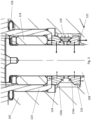
- FIG 2 shows a rotary valve 100 comprising a valve housing 102 which defines a fluid flow path 104.
- the rotary valve 100 comprises a valve disk 106 connected to a shaft 108 that are arranged to control the pressure and the flow of (high pressure) fluid through the flow path 4.
- the valve housing 102 comprises a bore 112 formed therein and through which the shaft 108 extends.
- Figure 3 shows an enlarged view of the region where the shaft 108 extends through the bore 112.
- a seal assembly 110 is positioned within the bore 112 and arranged to extend around the shaft 108 (the seal assembly 110 abuts against the outer circumferential surface of the shaft 108).
- the seal assembly 110 comprises a first seal ring 116, a second seal ring 118, and an elastic ring 120.
- the first seal ring 116 comprises a first ring angled surface 116a, which is a radially outward surface of the first seal ring 116, radially outward from the shaft 108.
- the second seal ring 118 comprises a second ring angle surface 118a, which is a radially outward surface of the second seal ring 118, radially outward from the shaft 108.
- the first ring angled surface 116a may be oriented at an angle that is the same as an angle of second ring angled surface 118a.
- the first ring angled surface 116a may be oriented at an angle different to an angle of the second ring angled surface 118a.
- the first ring angled surface 116a may be oriented at an angle between 30 and 60 degrees from the radially inward surface of the first seal ring 116.
- the second ring angled surface 118a may be oriented at an angle between 30 and 60 degrees from the radially inward surface of the second seal ring 118.
- the elastic ring 120 is positioned in contact with the first ring angled surface 116a and the second ring angled surface 118a. In other words, the elastic ring 120 is disposed radially outwardly from and axially between the first seal ring 116 and the second seal ring 118.
- the elastic ring 120 by virtue of its elastic properties, is configured to exert a radially inward force when it has been displaced (e.g. stretched) to a diameter greater than a rest diameter of the ring 120. As such, in the seal assembly 110, the elastic ring 120 is arranged to load against the angled surfaces 116a, 118a.
- the elastic ring 120 may comprise a first radially inner angled surface configured to contact the first ring angled surface 116a and a second radially inner angled surface configured to contact the second ring angled surface 118a.
- An angle of the first radially inner angled surface may correspond to an angle of the first ring angled surface 116a.
- An angle of the second radially inner angled surface may correspond to an angle of the second ring angled surface 118a.
- the angle of the first radially inner angled surface may be different or the same as the angle of the second radially inner angled surface.
- the first seal ring 116 and second seal ring 118 abut against the outer circumferential surface of the shaft 108, and the elastic ring 120 is spaced apart from the outer circumferential surface of the shaft 108.
- the elastic ring 120 as it is not in contact with the rotatable shaft 108, does not load against the shaft 108 and thus the angled surfaces 116a, 118a receive the full load of the elastic ring 120.
- the elastic ring 120 does not load against the shaft 108, it can be made of harder materials that, if it were in contact with the rotatable shaft 108, would wear/damage the shaft 108.
- the elastic ring 120 may be made from a high temperature superalloy, such as an austenitic nickel-chromium-based superalloy.
- a high temperature superalloy such as an austenitic nickel-chromium-based superalloy.
- Iconel 718 which is part of the family of metals manufactured by the Special Metals Corporation of New York state, USA.
- the first and second seal rings 116, 118 may be made from a soft material such as graphite (that will reduce wear on the shaft 108).
- the first and second seal rings 116, 118 can also be made from a high temperature superalloy (such as, for example Iconel 718).
- the shaft 108 and other parts of the valve 100 that are in contact with the first and second seal rings 116, 118 may be provided with a protective metal coating.
- the force exerted by the elastic ring 120 both biases the first seal ring 116 and the second seal ring 118 radially inward (e.g. to seal the seal assembly 110 against the shaft 108) and also biases the first seal ring 116 and the second seal ring 118 apart from one another.
- a seal 110 is therefore particularly able to provide significantly improved sealing performance when it is provided around a shaft 108 in a bore 112 which has axial structures that the rings are arranged to load/brace against.
- the bore 112 comprises an annular shoulder 122 formed in the housing 102.
- the first seal ring 116 is arranged to load against the annular shoulder when the first seal ring 116 and second seal ring 118 are biased apart from one another by the elastic ring 120.
- annular bushing seat component 124 located in the bore 112 above the seal assembly 110, there is provided an annular bushing seat component 124.
- the annular bushing seat component 124 is fixed to the valve housing 102 and is configured to support a bushing 114 which is provided around shaft 108.
- the second seal ring 118 is arranged to load against the bushing seat component 124 when the first seal ring 116 and second seal ring 118 are biased apart from one another by the elastic ring 120.
- the first seal ring 116 effectively seals against the shaft 108 and the housing 102
- the second seal ring 118 effectively seals against the shaft 108 and the annular bushing seat component 124.
- the rotary valve 100 may also comprise an annular static seal 126 (e.g. an O-ring) located between the bushing seat component 124 and the valve housing 102. As these components are fixed relative to each other, the static seal 126 is able to provide excellent sealing properties.
- annular static seal 126 e.g. an O-ring
- the shaft 108 of the rotary valve 100 is rotated (for example, under the control of an actuator) in order to rotate the valve disk 106 and change how much the valve disk 106 obstructs the flow path 104, thus controlling the flow of the high pressure gas in the flow path 104.
- the force applied by the elastic ring 120 against the first ring angled surface 116a seals the first seal ring against the shaft 108 and valve housing 102 and prevents the leakage of gas from the flow path 104 into the bore 112.
- the seal assembly 110 may be arranged to provide a sealing pressure between the first seal ring 116 and the housing 102 that is less than a sealing pressure between the first seal ring 116 and the shaft 108, so that in the event of a high pressure leak the gas passes between the first seal ring 116 and the housing 102 and not between the first seal ring 116 and the shaft 108. This may be done by adjusting the angle of the first ring angled surface 116a, for example.
- the force applied by the elastic ring 120 to the first ring angled surface 116a (and the second ring angled surface 118a) is increased by the increase in pressure in the region radially outward from the seal assembly 110.
- This increase in force allows the first seal ring 116 to be loaded back up against the housing 102 and reinstate the seal, preventing further leakage of gas from the flow path 104 into the bore 112.
- the increase in pressure also increases the sealing force between the second sealing ring 118 and the bushing seat component 124, preventing fluid in the region radially outward from the seal assembly 110 from leaking between these components.
- the static seal 126 when working in conjunction with the seal assembly 120, is able to prevent gas from leaking between the bushing seat component 124 and the valve housing 102 from the bore 112 to the external environment of the valve 100.
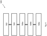
- Figure 4 shows a flow chart of a method 500 of making a rotary valve.
- a housing is provided defining a fluid flow path and having a bore
- a shaft is provided in the bore and connected the shaft to a valve disk disposed in the flow path.
- the seal assembly 100 is then installed around the shaft and within the bore. This may involve step 506a of installing the first seal ring around the shaft and within the bore; step 506b of installing the second seal ring around the shaft and within the bore; and step 506c of installing the elastic ring between the first seal ring and the second seal ring and in contact with the angled surfaces.
Landscapes
- Engineering & Computer Science (AREA)
- General Engineering & Computer Science (AREA)
- Mechanical Engineering (AREA)
- Lift Valve (AREA)
Claims (12)
- Drehventil (100), Folgendes umfassend:ein Gehäuse (102), das einen Fluidströmungsweg (104) definiert; eine Ventilscheibe (106), die in dem Strömungsweg angebracht ist, wobei die Scheibe so angeordnet ist, dass sie den Strömungsweg blockiert, wenn sich die Scheibe in einer ersten Drehposition befindet;eine Welle (108), die sich durch eine Bohrung (112) in dem Gehäuse erstreckt und mit der Scheibe so verbunden ist, dass eine Drehung der Welle eine Drehung der Scheibe innerhalb des Strömungswegs bewirkt; undeine Dichtungsanordnung (110), die so angeordnet ist, dass sie sich um eine äußere Umfangsfläche der Welle erstreckt und eine Fluidströmung aus dem Strömungsweg durch die Bohrung verhindert, und wobei die Dichtungsanordnung Folgendes umfasst:einen ersten Dichtungsring (116) mit einer ersten abgewinkelten Ringfläche (116a);einen zweiten Dichtungsring (118) mit einer zweiten abgewinkelten Ringfläche (118a); undeinen elastischen Ring (120), der zwischen dem ersten Dichtungsring und dem zweiten Dichtungsring angebracht ist und mit den abgewinkelten Flächen in Kontakt steht;wobei der elastische Ring (120) so angeordnet ist, dass er auf die abgewinkelten Flächen einwirkt, um den ersten Dichtungsring (116) und den zweiten Dichtungsring (118) radial nach innen und voneinander weg vorzuspannen;wobei eine ringförmige Schulter (122) in dem Gehäuse um die Bohrung (112) herum ausgebildet ist und wobei der erste Dichtungsring so angeordnet ist, dass er gegen die ringförmige Schulter drückt, wenn der erste Dichtungsring und der zweite Dichtungsring voneinander weg vorgespannt sind; undwobei die Dichtungsanordnung (110) so angeordnet ist, dass sie einen Dichtungsdruck zwischen dem ersten Dichtungsring und der ringförmigen Schulter bereitstellt, der geringer ist als ein Dichtungsdruck zwischen dem ersten Dichtungsring und der Welle, sodass bei Verwendung Fluid, das aus dem Strömungsweg in die Bohrung austritt, zwischen dem ersten Dichtungsring und der ringförmigen Schulter hindurchtritt, um den Druck zu erhöhen, der auf die radial äußere Fläche des elastischen Rings und die radial äußeren Flächen des ersten Dichtungsrings und des zweiten Dichtungsrings wirkt, was wiederum die Kraft erhöht, die den ersten Dichtungsring und den zweiten Dichtungsring radial nach innen und voneinander weg vorspannt.
- Ventil nach Anspruch 1, wobei der elastische Ring (120) so angeordnet ist, dass ein auf eine radial nach außen gerichtete Fläche des elastischen Rings ausgeübter Druck die Kraft erhöht, die den ersten Dichtungsring (116) und den zweiten Dichtungsring (118) radial nach innen und voneinander weg vorspannt.
- Ventil nach Anspruch 1 oder Anspruch 2, wobei der elastische Ring (120) eine erste radial innere abgewinkelte Fläche, die so konfiguriert ist, dass sie mit der ersten abgewinkelten Ringfläche (116a) in Kontakt kommt, und eine zweite radial innere abgewinkelte Fläche, die so konfiguriert ist, dass sie mit der zweiten abgewinkelten Ringfläche (118a) in Kontakt kommt, umfasst.
- Ventil nach einem der vorhergehenden Ansprüche, wobei ein Innendurchmesser des ersten Dichtungsrings (116) und ein Innendurchmesser des zweiten Dichtungsrings (118) jeweils kleiner sind als ein Innendurchmesser des elastischen Rings (120) .
- Ventil nach einem der vorhergehenden Ansprüche, wobei der erste Dichtungsring (116) und der zweite Dichtungsring (118) jeweils Graphit umfassen und wobei der elastische Dichtungsring (120) eine Hochtemperatur-Superlegierung umfasst.
- Ventil nach einem der Ansprüche 1 bis 4, wobei der erste Dichtungsring (116), der zweite Dichtungsring (118) und der elastische Dichtungsring (120) jeweils eine Hochtemperatur-Superlegierung umfassen.
- Ventil nach Anspruch 5 oder Anspruch 6, wobei die Hochtemperatur-Superlegierung eine austenitische Superlegierung auf Nickel-Chrom-Basis ist.
- Ventil nach einem der vorhergehenden Ansprüche, umfassend ein ringförmiges Buchsensitzbauteil (124), das an dem Gehäuse (102) befestigt ist und sich innerhalb der Bohrung (112) und um die Welle (108) herum befindet; wobei der zweite Dichtungsring (118) so angeordnet ist, dass er gegen das Buchsensitzbauteil drückt, wenn der erste Dichtungsring und der zweite Dichtungsring auseinander gedrückt werden.
- Ventil nach Anspruch 8, umfassend eine ringförmige statische Dichtung (126), die sich zwischen dem Buchsensitzbauteil (124) und dem Gehäuse (102) befindet.
- Ventil nach einem der vorhergehenden Ansprüche, wobei bei Verwendung das Fluid in dem Strömungsweg (104) ein Hochdruckgas ist.
- Verfahren (500) zum Herstellen eines Drehventils (100) nach einem der vorhergehenden Ansprüche, wobei das Verfahren Folgendes umfasst:Bereitstellen (502) des Gehäuses (102), das den Fluidströmungsweg (104) definiert und die Bohrung (112) aufweist;Bereitstellen (504) der Welle (108) in der Bohrung und Verbinden der Welle mit der in dem Strömungsweg angebrachten Ventilscheibe (106); undEinbauen (506) der Dichtungsanordnung (100) um die Welle und innerhalb der Bohrung.
- Verfahren (500) nach Anspruch 11, wobei das Einbauen (506) der Dichtungsanordnung (100) Folgendes umfasst:Einbauen (506a) des ersten Dichtungsrings (116) um die Welle (108) und innerhalb der Bohrung (112);Einbauen (506b) des zweiten Dichtungsrings (118) um die Welle und innerhalb der Bohrung; undEinbauen (506c) des elastischen Rings (120) zwischen dem ersten Dichtungsring und dem zweiten Dichtungsring und in Kontakt mit den abgewinkelten Flächen.
Priority Applications (3)
| Application Number | Priority Date | Filing Date | Title |
|---|---|---|---|
| EP22151061.3A EP4209694B1 (de) | 2022-01-11 | 2022-01-11 | Dichtungsanordnung für ein drehventil |
| CA3181325A CA3181325A1 (en) | 2022-01-11 | 2022-11-02 | Seal assembly for a rotary valve |
| US18/153,058 US12234927B2 (en) | 2022-01-11 | 2023-01-11 | Seal assembly for a rotary valve |
Applications Claiming Priority (1)
| Application Number | Priority Date | Filing Date | Title |
|---|---|---|---|
| EP22151061.3A EP4209694B1 (de) | 2022-01-11 | 2022-01-11 | Dichtungsanordnung für ein drehventil |
Publications (2)
| Publication Number | Publication Date |
|---|---|
| EP4209694A1 EP4209694A1 (de) | 2023-07-12 |
| EP4209694B1 true EP4209694B1 (de) | 2024-09-18 |
Family
ID=79316648
Family Applications (1)
| Application Number | Title | Priority Date | Filing Date |
|---|---|---|---|
| EP22151061.3A Active EP4209694B1 (de) | 2022-01-11 | 2022-01-11 | Dichtungsanordnung für ein drehventil |
Country Status (3)
| Country | Link |
|---|---|
| US (1) | US12234927B2 (de) |
| EP (1) | EP4209694B1 (de) |
| CA (1) | CA3181325A1 (de) |
Families Citing this family (1)
| Publication number | Priority date | Publication date | Assignee | Title |
|---|---|---|---|---|
| DE102022120289A1 (de) * | 2022-08-11 | 2024-02-22 | Purem GmbH | Stellklappenbaugruppe für einen Gasstrom in einem Brennstoffzellensystem |
Family Cites Families (21)
| Publication number | Priority date | Publication date | Assignee | Title |
|---|---|---|---|---|
| US1175383A (en) * | 1914-08-03 | 1916-03-14 | Buffum Tool Company | Piston packing-ring. |
| US2034227A (en) * | 1934-02-09 | 1936-03-17 | Thompson Prod Inc | Seal for bearings |
| US2931671A (en) * | 1957-03-25 | 1960-04-05 | Howard K Beeley | Seals for gas carrying pipe lines |
| US3068054A (en) * | 1961-11-13 | 1962-12-11 | Dagobert O Schmidt | Pressure sealing piston and ring unit |
| US3218087A (en) * | 1962-07-09 | 1965-11-16 | Boeing Co | Foot seal |
| US3614114A (en) * | 1969-07-14 | 1971-10-19 | Shamban & Co W S | Seal assembly |
| GB1285272A (en) * | 1970-04-01 | 1972-08-16 | Hallite Holdings Ltd | Gland seal assemblies |
| US4022424A (en) * | 1975-09-29 | 1977-05-10 | General Electric Company | Shaft bearing and seals for butterfly valves |
| US4032159A (en) * | 1975-10-28 | 1977-06-28 | Poly Seal, Inc. | Interference compression seal |
| DE2829029A1 (de) * | 1978-07-01 | 1980-01-10 | Bosch Gmbh Robert | Dichtungsanordnung fuer druckmittelbeaufschlagte teile |
| US4394023A (en) | 1982-09-29 | 1983-07-19 | Daniel Industries Inc. | High temperature valve stem packing with coiled graphite seal rings |
| FR2590641B1 (fr) * | 1985-11-25 | 1989-07-13 | Snecma | Dispositif composite d'etancheite |
| US5370361A (en) * | 1994-04-25 | 1994-12-06 | The Boc Group, Inc. | Butterfly valve |
| FR2755490B1 (fr) * | 1996-11-07 | 1999-05-14 | Poclain Hydraulics Sa | Assemblage a joint d'etancheite |
| US7828301B2 (en) * | 2008-01-25 | 2010-11-09 | Intelliserv, Llc | Self-energized backup ring for annular seals |
| US20120104300A1 (en) | 2010-10-29 | 2012-05-03 | Dowd Peter J | Composite seal |
| CN104048060B (zh) | 2013-03-14 | 2018-02-16 | 费希尔控制国际公司 | 一种用于高温控制阀的石墨金属阀密封组件 |
| US9863552B2 (en) | 2014-06-24 | 2018-01-09 | Jdv Control Valves Co., Ltd. | Fluid valve and a single shaft-sealing module thereof |
| DE102016208697A1 (de) * | 2016-05-20 | 2017-11-23 | Trelleborg Sealing Solutions Germany Gmbh | Rotationsdichtungsanordnung mit druckaktivierbarer Rotationsdichtung sowie Rotationsdichtung |
| US10598035B2 (en) | 2016-05-27 | 2020-03-24 | General Electric Company | Intershaft sealing systems for gas turbine engines and methods for assembling the same |
| US11300229B2 (en) * | 2019-07-11 | 2022-04-12 | Performance Oil Tools, Inc. | Packing module and stuffing box assembly |
-
2022
- 2022-01-11 EP EP22151061.3A patent/EP4209694B1/de active Active
- 2022-11-02 CA CA3181325A patent/CA3181325A1/en active Pending
-
2023
- 2023-01-11 US US18/153,058 patent/US12234927B2/en active Active
Also Published As
| Publication number | Publication date |
|---|---|
| CA3181325A1 (en) | 2023-07-11 |
| US12234927B2 (en) | 2025-02-25 |
| US20230220930A1 (en) | 2023-07-13 |
| EP4209694A1 (de) | 2023-07-12 |
Similar Documents
| Publication | Publication Date | Title |
|---|---|---|
| US4231546A (en) | High-temperature bidirectional metal seal | |
| US4602762A (en) | Ball valve and seat assembly | |
| US6655693B2 (en) | Non-contacting gas compressor seal | |
| JP5960684B2 (ja) | スリーブシール組立体およびスリーブシール組立体を有するロータリ弁 | |
| EP0163450B1 (de) | Gleitringdichtung | |
| US4289296A (en) | Bidirectional axially pliant pressure assisted seat for a valve | |
| CA3095065A1 (en) | Valve seats, valve assemblies, and related methods | |
| US4410165A (en) | Ball valve and seat assembly | |
| EP0110012B1 (de) | Ventileinheit | |
| EP4209694B1 (de) | Dichtungsanordnung für ein drehventil | |
| EP0675304B1 (de) | Dichtung | |
| US7249768B2 (en) | Shaft seal assembly and method | |
| CA1133877A (en) | Ball valve and seat assembly | |
| GB1561593A (en) | Valve structure | |
| US8608175B2 (en) | Mechanical face seal stop pin | |
| US8523186B2 (en) | Slide ring seal arrangement | |
| US4373543A (en) | Fire resistant seat for flow control valve | |
| JP3815669B2 (ja) | ボールバルブ | |
| BR102022021883A2 (pt) | Conjunto de vedação para um eixo, válvula rotativa, e, método para fazer uma válvula rotativa | |
| AU2023247816B2 (en) | Sealing system with extra pressure protection, machine and method | |
| US11236830B2 (en) | Seal glands for butterfly valves | |
| JP2024110622A (ja) | 密封装置および軸受 | |
| KR20240091277A (ko) | 회전 장비용 원추형 밀봉 조립체 및 이를 포함하는 회전 장비 | |
| Keba | Shaft seal assembly and method |
Legal Events
| Date | Code | Title | Description |
|---|---|---|---|
| PUAI | Public reference made under article 153(3) epc to a published international application that has entered the european phase |
Free format text: ORIGINAL CODE: 0009012 |
|
| STAA | Information on the status of an ep patent application or granted ep patent |
Free format text: STATUS: THE APPLICATION HAS BEEN PUBLISHED |
|
| AK | Designated contracting states |
Kind code of ref document: A1 Designated state(s): AL AT BE BG CH CY CZ DE DK EE ES FI FR GB GR HR HU IE IS IT LI LT LU LV MC MK MT NL NO PL PT RO RS SE SI SK SM TR |
|
| STAA | Information on the status of an ep patent application or granted ep patent |
Free format text: STATUS: REQUEST FOR EXAMINATION WAS MADE |
|
| 17P | Request for examination filed |
Effective date: 20240112 |
|
| RBV | Designated contracting states (corrected) |
Designated state(s): AL AT BE BG CH CY CZ DE DK EE ES FI FR GB GR HR HU IE IS IT LI LT LU LV MC MK MT NL NO PL PT RO RS SE SI SK SM TR |
|
| GRAP | Despatch of communication of intention to grant a patent |
Free format text: ORIGINAL CODE: EPIDOSNIGR1 |
|
| STAA | Information on the status of an ep patent application or granted ep patent |
Free format text: STATUS: GRANT OF PATENT IS INTENDED |
|
| INTG | Intention to grant announced |
Effective date: 20240423 |
|
| RIN1 | Information on inventor provided before grant (corrected) |
Inventor name: SALVATORIELLO, GIANFRANCO Inventor name: MANTIA, ELLIO Inventor name: MORNACCHI, ANDREA |
|
| GRAS | Grant fee paid |
Free format text: ORIGINAL CODE: EPIDOSNIGR3 |
|
| GRAA | (expected) grant |
Free format text: ORIGINAL CODE: 0009210 |
|
| STAA | Information on the status of an ep patent application or granted ep patent |
Free format text: STATUS: THE PATENT HAS BEEN GRANTED |
|
| AK | Designated contracting states |
Kind code of ref document: B1 Designated state(s): AL AT BE BG CH CY CZ DE DK EE ES FI FR GB GR HR HU IE IS IT LI LT LU LV MC MK MT NL NO PL PT RO RS SE SI SK SM TR |
|
| REG | Reference to a national code |
Ref country code: GB Ref legal event code: FG4D |
|
| REG | Reference to a national code |
Ref country code: CH Ref legal event code: EP |
|
| REG | Reference to a national code |
Ref country code: DE Ref legal event code: R096 Ref document number: 602022006089 Country of ref document: DE |
|
| REG | Reference to a national code |
Ref country code: IE Ref legal event code: FG4D |
|
| REG | Reference to a national code |
Ref country code: LT Ref legal event code: MG9D |
|
| PG25 | Lapsed in a contracting state [announced via postgrant information from national office to epo] |
Ref country code: NO Free format text: LAPSE BECAUSE OF FAILURE TO SUBMIT A TRANSLATION OF THE DESCRIPTION OR TO PAY THE FEE WITHIN THE PRESCRIBED TIME-LIMIT Effective date: 20241218 |
|
| PG25 | Lapsed in a contracting state [announced via postgrant information from national office to epo] |
Ref country code: GR Free format text: LAPSE BECAUSE OF FAILURE TO SUBMIT A TRANSLATION OF THE DESCRIPTION OR TO PAY THE FEE WITHIN THE PRESCRIBED TIME-LIMIT Effective date: 20241219 Ref country code: FI Free format text: LAPSE BECAUSE OF FAILURE TO SUBMIT A TRANSLATION OF THE DESCRIPTION OR TO PAY THE FEE WITHIN THE PRESCRIBED TIME-LIMIT Effective date: 20240918 |
|
| PG25 | Lapsed in a contracting state [announced via postgrant information from national office to epo] |
Ref country code: BG Free format text: LAPSE BECAUSE OF FAILURE TO SUBMIT A TRANSLATION OF THE DESCRIPTION OR TO PAY THE FEE WITHIN THE PRESCRIBED TIME-LIMIT Effective date: 20240918 |
|
| PGFP | Annual fee paid to national office [announced via postgrant information from national office to epo] |
Ref country code: FR Payment date: 20241219 Year of fee payment: 4 |
|
| PG25 | Lapsed in a contracting state [announced via postgrant information from national office to epo] |
Ref country code: LV Free format text: LAPSE BECAUSE OF FAILURE TO SUBMIT A TRANSLATION OF THE DESCRIPTION OR TO PAY THE FEE WITHIN THE PRESCRIBED TIME-LIMIT Effective date: 20240918 |
|
| PG25 | Lapsed in a contracting state [announced via postgrant information from national office to epo] |
Ref country code: HR Free format text: LAPSE BECAUSE OF FAILURE TO SUBMIT A TRANSLATION OF THE DESCRIPTION OR TO PAY THE FEE WITHIN THE PRESCRIBED TIME-LIMIT Effective date: 20240918 |
|
| REG | Reference to a national code |
Ref country code: NL Ref legal event code: MP Effective date: 20240918 |
|
| PG25 | Lapsed in a contracting state [announced via postgrant information from national office to epo] |
Ref country code: RS Free format text: LAPSE BECAUSE OF FAILURE TO SUBMIT A TRANSLATION OF THE DESCRIPTION OR TO PAY THE FEE WITHIN THE PRESCRIBED TIME-LIMIT Effective date: 20241218 |
|
| PG25 | Lapsed in a contracting state [announced via postgrant information from national office to epo] |
Ref country code: RS Free format text: LAPSE BECAUSE OF FAILURE TO SUBMIT A TRANSLATION OF THE DESCRIPTION OR TO PAY THE FEE WITHIN THE PRESCRIBED TIME-LIMIT Effective date: 20241218 Ref country code: NO Free format text: LAPSE BECAUSE OF FAILURE TO SUBMIT A TRANSLATION OF THE DESCRIPTION OR TO PAY THE FEE WITHIN THE PRESCRIBED TIME-LIMIT Effective date: 20241218 Ref country code: LV Free format text: LAPSE BECAUSE OF FAILURE TO SUBMIT A TRANSLATION OF THE DESCRIPTION OR TO PAY THE FEE WITHIN THE PRESCRIBED TIME-LIMIT Effective date: 20240918 Ref country code: HR Free format text: LAPSE BECAUSE OF FAILURE TO SUBMIT A TRANSLATION OF THE DESCRIPTION OR TO PAY THE FEE WITHIN THE PRESCRIBED TIME-LIMIT Effective date: 20240918 Ref country code: GR Free format text: LAPSE BECAUSE OF FAILURE TO SUBMIT A TRANSLATION OF THE DESCRIPTION OR TO PAY THE FEE WITHIN THE PRESCRIBED TIME-LIMIT Effective date: 20241219 Ref country code: FI Free format text: LAPSE BECAUSE OF FAILURE TO SUBMIT A TRANSLATION OF THE DESCRIPTION OR TO PAY THE FEE WITHIN THE PRESCRIBED TIME-LIMIT Effective date: 20240918 Ref country code: BG Free format text: LAPSE BECAUSE OF FAILURE TO SUBMIT A TRANSLATION OF THE DESCRIPTION OR TO PAY THE FEE WITHIN THE PRESCRIBED TIME-LIMIT Effective date: 20240918 |
|
| REG | Reference to a national code |
Ref country code: AT Ref legal event code: MK05 Ref document number: 1724942 Country of ref document: AT Kind code of ref document: T Effective date: 20240918 |
|
| PG25 | Lapsed in a contracting state [announced via postgrant information from national office to epo] |
Ref country code: NL Free format text: LAPSE BECAUSE OF FAILURE TO SUBMIT A TRANSLATION OF THE DESCRIPTION OR TO PAY THE FEE WITHIN THE PRESCRIBED TIME-LIMIT Effective date: 20240918 |
|
| PG25 | Lapsed in a contracting state [announced via postgrant information from national office to epo] |
Ref country code: PT Free format text: LAPSE BECAUSE OF FAILURE TO SUBMIT A TRANSLATION OF THE DESCRIPTION OR TO PAY THE FEE WITHIN THE PRESCRIBED TIME-LIMIT Effective date: 20250120 Ref country code: IS Free format text: LAPSE BECAUSE OF FAILURE TO SUBMIT A TRANSLATION OF THE DESCRIPTION OR TO PAY THE FEE WITHIN THE PRESCRIBED TIME-LIMIT Effective date: 20250118 |
|
| PGFP | Annual fee paid to national office [announced via postgrant information from national office to epo] |
Ref country code: DE Payment date: 20241218 Year of fee payment: 4 |
|
| PG25 | Lapsed in a contracting state [announced via postgrant information from national office to epo] |
Ref country code: SM Free format text: LAPSE BECAUSE OF FAILURE TO SUBMIT A TRANSLATION OF THE DESCRIPTION OR TO PAY THE FEE WITHIN THE PRESCRIBED TIME-LIMIT Effective date: 20240918 Ref country code: RO Free format text: LAPSE BECAUSE OF FAILURE TO SUBMIT A TRANSLATION OF THE DESCRIPTION OR TO PAY THE FEE WITHIN THE PRESCRIBED TIME-LIMIT Effective date: 20240918 |
|
| PG25 | Lapsed in a contracting state [announced via postgrant information from national office to epo] |
Ref country code: ES Free format text: LAPSE BECAUSE OF FAILURE TO SUBMIT A TRANSLATION OF THE DESCRIPTION OR TO PAY THE FEE WITHIN THE PRESCRIBED TIME-LIMIT Effective date: 20240918 |
|
| PG25 | Lapsed in a contracting state [announced via postgrant information from national office to epo] |
Ref country code: AT Free format text: LAPSE BECAUSE OF FAILURE TO SUBMIT A TRANSLATION OF THE DESCRIPTION OR TO PAY THE FEE WITHIN THE PRESCRIBED TIME-LIMIT Effective date: 20240918 Ref country code: EE Free format text: LAPSE BECAUSE OF FAILURE TO SUBMIT A TRANSLATION OF THE DESCRIPTION OR TO PAY THE FEE WITHIN THE PRESCRIBED TIME-LIMIT Effective date: 20240918 |
|
| PG25 | Lapsed in a contracting state [announced via postgrant information from national office to epo] |
Ref country code: PL Free format text: LAPSE BECAUSE OF FAILURE TO SUBMIT A TRANSLATION OF THE DESCRIPTION OR TO PAY THE FEE WITHIN THE PRESCRIBED TIME-LIMIT Effective date: 20240918 Ref country code: CZ Free format text: LAPSE BECAUSE OF FAILURE TO SUBMIT A TRANSLATION OF THE DESCRIPTION OR TO PAY THE FEE WITHIN THE PRESCRIBED TIME-LIMIT Effective date: 20240918 |
|
| PG25 | Lapsed in a contracting state [announced via postgrant information from national office to epo] |
Ref country code: SK Free format text: LAPSE BECAUSE OF FAILURE TO SUBMIT A TRANSLATION OF THE DESCRIPTION OR TO PAY THE FEE WITHIN THE PRESCRIBED TIME-LIMIT Effective date: 20240918 |
|
| PGFP | Annual fee paid to national office [announced via postgrant information from national office to epo] |
Ref country code: IT Payment date: 20250131 Year of fee payment: 4 |
|
| REG | Reference to a national code |
Ref country code: DE Ref legal event code: R097 Ref document number: 602022006089 Country of ref document: DE |
|
| PG25 | Lapsed in a contracting state [announced via postgrant information from national office to epo] |
Ref country code: DK Free format text: LAPSE BECAUSE OF FAILURE TO SUBMIT A TRANSLATION OF THE DESCRIPTION OR TO PAY THE FEE WITHIN THE PRESCRIBED TIME-LIMIT Effective date: 20240918 |
|
| PLBE | No opposition filed within time limit |
Free format text: ORIGINAL CODE: 0009261 |
|
| STAA | Information on the status of an ep patent application or granted ep patent |
Free format text: STATUS: NO OPPOSITION FILED WITHIN TIME LIMIT |
|
| 26N | No opposition filed |
Effective date: 20250619 |
|
| REG | Reference to a national code |
Ref country code: CH Ref legal event code: PL |
|
| PG25 | Lapsed in a contracting state [announced via postgrant information from national office to epo] |
Ref country code: SE Free format text: LAPSE BECAUSE OF FAILURE TO SUBMIT A TRANSLATION OF THE DESCRIPTION OR TO PAY THE FEE WITHIN THE PRESCRIBED TIME-LIMIT Effective date: 20240918 |
|
| PG25 | Lapsed in a contracting state [announced via postgrant information from national office to epo] |
Ref country code: LU Free format text: LAPSE BECAUSE OF NON-PAYMENT OF DUE FEES Effective date: 20250111 Ref country code: MC Free format text: LAPSE BECAUSE OF FAILURE TO SUBMIT A TRANSLATION OF THE DESCRIPTION OR TO PAY THE FEE WITHIN THE PRESCRIBED TIME-LIMIT Effective date: 20240918 |
|
| PG25 | Lapsed in a contracting state [announced via postgrant information from national office to epo] |
Ref country code: BE Free format text: LAPSE BECAUSE OF NON-PAYMENT OF DUE FEES Effective date: 20250131 |
|
| PG25 | Lapsed in a contracting state [announced via postgrant information from national office to epo] |
Ref country code: CH Free format text: LAPSE BECAUSE OF NON-PAYMENT OF DUE FEES Effective date: 20250131 |
|
| REG | Reference to a national code |
Ref country code: BE Ref legal event code: MM Effective date: 20250131 |