EP4209681A1 - Rotor formed of multiple metals - Google Patents
Rotor formed of multiple metals Download PDFInfo
- Publication number
- EP4209681A1 EP4209681A1 EP22212876.1A EP22212876A EP4209681A1 EP 4209681 A1 EP4209681 A1 EP 4209681A1 EP 22212876 A EP22212876 A EP 22212876A EP 4209681 A1 EP4209681 A1 EP 4209681A1
- Authority
- EP
- European Patent Office
- Prior art keywords
- rotor
- hub
- blades
- metal materials
- set forth
- Prior art date
- Legal status (The legal status is an assumption and is not a legal conclusion. Google has not performed a legal analysis and makes no representation as to the accuracy of the status listed.)
- Pending
Links
Images



Classifications
-
- F—MECHANICAL ENGINEERING; LIGHTING; HEATING; WEAPONS; BLASTING
- F04—POSITIVE - DISPLACEMENT MACHINES FOR LIQUIDS; PUMPS FOR LIQUIDS OR ELASTIC FLUIDS
- F04D—NON-POSITIVE-DISPLACEMENT PUMPS
- F04D29/00—Details, component parts, or accessories
- F04D29/26—Rotors specially for elastic fluids
- F04D29/28—Rotors specially for elastic fluids for centrifugal or helico-centrifugal pumps for radial-flow or helico-centrifugal pumps
- F04D29/284—Rotors specially for elastic fluids for centrifugal or helico-centrifugal pumps for radial-flow or helico-centrifugal pumps for compressors
-
- B—PERFORMING OPERATIONS; TRANSPORTING
- B22—CASTING; POWDER METALLURGY
- B22F—WORKING METALLIC POWDER; MANUFACTURE OF ARTICLES FROM METALLIC POWDER; MAKING METALLIC POWDER; APPARATUS OR DEVICES SPECIALLY ADAPTED FOR METALLIC POWDER
- B22F5/00—Manufacture of workpieces or articles from metallic powder characterised by the special shape of the product
- B22F5/04—Manufacture of workpieces or articles from metallic powder characterised by the special shape of the product of turbine blades
-
- B—PERFORMING OPERATIONS; TRANSPORTING
- B22—CASTING; POWDER METALLURGY
- B22F—WORKING METALLIC POWDER; MANUFACTURE OF ARTICLES FROM METALLIC POWDER; MAKING METALLIC POWDER; APPARATUS OR DEVICES SPECIALLY ADAPTED FOR METALLIC POWDER
- B22F10/00—Additive manufacturing of workpieces or articles from metallic powder
- B22F10/20—Direct sintering or melting
- B22F10/28—Powder bed fusion, e.g. selective laser melting [SLM] or electron beam melting [EBM]
-
- B—PERFORMING OPERATIONS; TRANSPORTING
- B22—CASTING; POWDER METALLURGY
- B22F—WORKING METALLIC POWDER; MANUFACTURE OF ARTICLES FROM METALLIC POWDER; MAKING METALLIC POWDER; APPARATUS OR DEVICES SPECIALLY ADAPTED FOR METALLIC POWDER
- B22F10/00—Additive manufacturing of workpieces or articles from metallic powder
- B22F10/30—Process control
- B22F10/38—Process control to achieve specific product aspects, e.g. surface smoothness, density, porosity or hollow structures
-
- B—PERFORMING OPERATIONS; TRANSPORTING
- B22—CASTING; POWDER METALLURGY
- B22F—WORKING METALLIC POWDER; MANUFACTURE OF ARTICLES FROM METALLIC POWDER; MAKING METALLIC POWDER; APPARATUS OR DEVICES SPECIALLY ADAPTED FOR METALLIC POWDER
- B22F7/00—Manufacture of composite layers, workpieces, or articles, comprising metallic powder, by sintering the powder, with or without compacting wherein at least one part is obtained by sintering or compression
- B22F7/06—Manufacture of composite layers, workpieces, or articles, comprising metallic powder, by sintering the powder, with or without compacting wherein at least one part is obtained by sintering or compression of composite workpieces or articles from parts, e.g. to form tipped tools
-
- B—PERFORMING OPERATIONS; TRANSPORTING
- B33—ADDITIVE MANUFACTURING TECHNOLOGY
- B33Y—ADDITIVE MANUFACTURING, i.e. MANUFACTURING OF THREE-DIMENSIONAL [3D] OBJECTS BY ADDITIVE DEPOSITION, ADDITIVE AGGLOMERATION OR ADDITIVE LAYERING, e.g. BY 3D PRINTING, STEREOLITHOGRAPHY OR SELECTIVE LASER SINTERING
- B33Y10/00—Processes of additive manufacturing
-
- B—PERFORMING OPERATIONS; TRANSPORTING
- B33—ADDITIVE MANUFACTURING TECHNOLOGY
- B33Y—ADDITIVE MANUFACTURING, i.e. MANUFACTURING OF THREE-DIMENSIONAL [3D] OBJECTS BY ADDITIVE DEPOSITION, ADDITIVE AGGLOMERATION OR ADDITIVE LAYERING, e.g. BY 3D PRINTING, STEREOLITHOGRAPHY OR SELECTIVE LASER SINTERING
- B33Y80/00—Products made by additive manufacturing
-
- F—MECHANICAL ENGINEERING; LIGHTING; HEATING; WEAPONS; BLASTING
- F01—MACHINES OR ENGINES IN GENERAL; ENGINE PLANTS IN GENERAL; STEAM ENGINES
- F01D—NON-POSITIVE DISPLACEMENT MACHINES OR ENGINES, e.g. STEAM TURBINES
- F01D5/00—Blades; Blade-carrying members; Heating, heat-insulating, cooling or antivibration means on the blades or the members
- F01D5/12—Blades
- F01D5/14—Form or construction
-
- F—MECHANICAL ENGINEERING; LIGHTING; HEATING; WEAPONS; BLASTING
- F04—POSITIVE - DISPLACEMENT MACHINES FOR LIQUIDS; PUMPS FOR LIQUIDS OR ELASTIC FLUIDS
- F04D—NON-POSITIVE-DISPLACEMENT PUMPS
- F04D17/00—Radial-flow pumps, e.g. centrifugal pumps; Helico-centrifugal pumps
- F04D17/08—Centrifugal pumps
- F04D17/10—Centrifugal pumps for compressing or evacuating
-
- F—MECHANICAL ENGINEERING; LIGHTING; HEATING; WEAPONS; BLASTING
- F04—POSITIVE - DISPLACEMENT MACHINES FOR LIQUIDS; PUMPS FOR LIQUIDS OR ELASTIC FLUIDS
- F04D—NON-POSITIVE-DISPLACEMENT PUMPS
- F04D25/00—Pumping installations or systems
- F04D25/02—Units comprising pumps and their driving means
- F04D25/06—Units comprising pumps and their driving means the pump being electrically driven
-
- F—MECHANICAL ENGINEERING; LIGHTING; HEATING; WEAPONS; BLASTING
- F04—POSITIVE - DISPLACEMENT MACHINES FOR LIQUIDS; PUMPS FOR LIQUIDS OR ELASTIC FLUIDS
- F04D—NON-POSITIVE-DISPLACEMENT PUMPS
- F04D29/00—Details, component parts, or accessories
- F04D29/02—Selection of particular materials
- F04D29/023—Selection of particular materials especially adapted for elastic fluid pumps
-
- F—MECHANICAL ENGINEERING; LIGHTING; HEATING; WEAPONS; BLASTING
- F04—POSITIVE - DISPLACEMENT MACHINES FOR LIQUIDS; PUMPS FOR LIQUIDS OR ELASTIC FLUIDS
- F04D—NON-POSITIVE-DISPLACEMENT PUMPS
- F04D29/00—Details, component parts, or accessories
- F04D29/26—Rotors specially for elastic fluids
- F04D29/28—Rotors specially for elastic fluids for centrifugal or helico-centrifugal pumps for radial-flow or helico-centrifugal pumps
- F04D29/30—Vanes
-
- F—MECHANICAL ENGINEERING; LIGHTING; HEATING; WEAPONS; BLASTING
- F04—POSITIVE - DISPLACEMENT MACHINES FOR LIQUIDS; PUMPS FOR LIQUIDS OR ELASTIC FLUIDS
- F04D—NON-POSITIVE-DISPLACEMENT PUMPS
- F04D29/00—Details, component parts, or accessories
- F04D29/58—Cooling; Heating; Diminishing heat transfer
- F04D29/582—Cooling; Heating; Diminishing heat transfer specially adapted for elastic fluid pumps
- F04D29/5853—Cooling; Heating; Diminishing heat transfer specially adapted for elastic fluid pumps heat insulation or conduction
-
- B—PERFORMING OPERATIONS; TRANSPORTING
- B22—CASTING; POWDER METALLURGY
- B22F—WORKING METALLIC POWDER; MANUFACTURE OF ARTICLES FROM METALLIC POWDER; MAKING METALLIC POWDER; APPARATUS OR DEVICES SPECIALLY ADAPTED FOR METALLIC POWDER
- B22F2999/00—Aspects linked to processes or compositions used in powder metallurgy
-
- B—PERFORMING OPERATIONS; TRANSPORTING
- B22—CASTING; POWDER METALLURGY
- B22F—WORKING METALLIC POWDER; MANUFACTURE OF ARTICLES FROM METALLIC POWDER; MAKING METALLIC POWDER; APPARATUS OR DEVICES SPECIALLY ADAPTED FOR METALLIC POWDER
- B22F5/00—Manufacture of workpieces or articles from metallic powder characterised by the special shape of the product
- B22F5/009—Manufacture of workpieces or articles from metallic powder characterised by the special shape of the product of turbine components other than turbine blades
-
- F—MECHANICAL ENGINEERING; LIGHTING; HEATING; WEAPONS; BLASTING
- F01—MACHINES OR ENGINES IN GENERAL; ENGINE PLANTS IN GENERAL; STEAM ENGINES
- F01D—NON-POSITIVE DISPLACEMENT MACHINES OR ENGINES, e.g. STEAM TURBINES
- F01D5/00—Blades; Blade-carrying members; Heating, heat-insulating, cooling or antivibration means on the blades or the members
- F01D5/02—Blade-carrying members, e.g. rotors
- F01D5/04—Blade-carrying members, e.g. rotors for radial-flow machines or engines
-
- F—MECHANICAL ENGINEERING; LIGHTING; HEATING; WEAPONS; BLASTING
- F01—MACHINES OR ENGINES IN GENERAL; ENGINE PLANTS IN GENERAL; STEAM ENGINES
- F01D—NON-POSITIVE DISPLACEMENT MACHINES OR ENGINES, e.g. STEAM TURBINES
- F01D5/00—Blades; Blade-carrying members; Heating, heat-insulating, cooling or antivibration means on the blades or the members
- F01D5/12—Blades
- F01D5/28—Selecting particular materials; Particular measures relating thereto; Measures against erosion or corrosion
-
- F—MECHANICAL ENGINEERING; LIGHTING; HEATING; WEAPONS; BLASTING
- F05—INDEXING SCHEMES RELATING TO ENGINES OR PUMPS IN VARIOUS SUBCLASSES OF CLASSES F01-F04
- F05D—INDEXING SCHEME FOR ASPECTS RELATING TO NON-POSITIVE-DISPLACEMENT MACHINES OR ENGINES, GAS-TURBINES OR JET-PROPULSION PLANTS
- F05D2230/00—Manufacture
- F05D2230/30—Manufacture with deposition of material
- F05D2230/31—Layer deposition
-
- F—MECHANICAL ENGINEERING; LIGHTING; HEATING; WEAPONS; BLASTING
- F05—INDEXING SCHEMES RELATING TO ENGINES OR PUMPS IN VARIOUS SUBCLASSES OF CLASSES F01-F04
- F05D—INDEXING SCHEME FOR ASPECTS RELATING TO NON-POSITIVE-DISPLACEMENT MACHINES OR ENGINES, GAS-TURBINES OR JET-PROPULSION PLANTS
- F05D2300/00—Materials; Properties thereof
- F05D2300/50—Intrinsic material properties or characteristics
- F05D2300/502—Thermal properties
- F05D2300/5021—Expansivity
- F05D2300/50212—Expansivity dissimilar
-
- F—MECHANICAL ENGINEERING; LIGHTING; HEATING; WEAPONS; BLASTING
- F05—INDEXING SCHEMES RELATING TO ENGINES OR PUMPS IN VARIOUS SUBCLASSES OF CLASSES F01-F04
- F05D—INDEXING SCHEME FOR ASPECTS RELATING TO NON-POSITIVE-DISPLACEMENT MACHINES OR ENGINES, GAS-TURBINES OR JET-PROPULSION PLANTS
- F05D2300/00—Materials; Properties thereof
- F05D2300/50—Intrinsic material properties or characteristics
- F05D2300/505—Shape memory behaviour
Definitions
- This application relates to a method of forming a rotor, and a rotor, wherein the rotor is formed of at least two distinct metals to result in the rotor being more resistant to forces it may experience.
- Rotors are utilized in any number of machine applications.
- a compressor to supply air into the cabin of an aircraft is driven by an electric motor.
- the compressor has a hub and blades extending radially outwardly of the hub.
- Such compressors can be subject to high temperature and stress.
- a rotor for a machine including a hub having a plurality of blades extending radially outwardly of the hub. At least one of the hub and the plurality of blades is formed of at least two metal materials.
- the two metal materials are selected to have different thermal expansion coefficients such that the overall rotor will be more resistant to forces it may experience as temperature or speed increases. There are layers of each of the two metal materials, with an intermediate gradient wherein the two materials are mixed.
- a shape memory alloy is used to provide the resistance.
- FIG. 1 shows a fan system 20.
- a source 10 delivers gas to an inlet 11 in a fan housing 22.
- the gas may be air.
- the air approaches a rotor 26 having a hub 100 with an outer surface at 28.
- a plurality of fan blades 30 have a leading edge 32 and a trailing edge 34.
- a shroud 31 surrounds rotor 26.
- a diffuser housing 38 is aft of the impeller 26.
- An electric motor 47 has a rotor 48 and a stator 50.
- the rotor 48 is driven to rotate, as known, and drives a shaft 42.
- Shaft 42 is secured to rotor 26 with a connection shown at 44, and including a nut 46.
- a bearing 40 supports the shaft 42.
- Rotor 26 moves air to outlet 36.
- source 10 is an aircraft cabin that recirculates air back into a use 12 that may be a mixing chamber where it is mixed with air from an air cycle machine. The mixed air is returned to the
- rotor 26 includes hub 100 and blades 30 attached to and extending outward from hub 100.
- FIG. 3A shows hub 100 and blades 30 each including exterior surface 140 that surrounds lattice structure 142 in an interior of hub 100 and blades 30.
- Exterior surface 140 is a solid, continuous surface.
- Lattice structure 142 is a varying lattice structure.
- Lattice structure 142 has regions with varying densities. As shown, lattice structure 142 has first region 150, second region 152, third region 154, fourth region 156, fifth region 158, sixth region 160, seventh region 162, and eighth region 164 in hub 100, and ninth region 166 and tenth region 168 in blades 30. The regions have different densities to provide increased stiffness at particular high density locations and lower density at other less challenging areas to reduce weight.
- Lattice structure 142 may vary gradually or abruptly between regions.
- Lattice structure 142 includes members 198 arranged in a 3D crisscrossing pattern with voids 200 between the members.
- lattice structure 142 varies in density by having a varying distribution of the members 198 and voids 200 of lattice structure 142.
- lattice structure 142 can vary in density by varying the thickness of the members 198, by having varying geometrical configurations, and/or by varying fillet radii on joints between the members.
- first region 150, third region 154, fifth region 158, seventh region 162, ninth region 166, and tenth region 168 have a greater density than second region 152, fourth region 156, sixth region 160, and eighth region 164.
- Rotor 26 is additively manufactured, allowing lattice structure 142 to be manufactured with different densities in different areas of rotor 26. Any suitable additive manufacturing process (also known as a 3D printing process) can be used to manufacture rotor 26, including, for example, direct metal laser sintering, electron beam freeform fabrication, electron-beam melting, selective laser melting, or selective laser sintering.
- Rotor 26 can be made out of any material that can be used in an additive manufacturing process, including any of stainless steel, corrosion-resistant steel, nickel-chromium alloy, titanium, aluminum, synthetic fiber, fiberglass, composites, and combinations thereof.
- rotor 26 Traditional rotors for rotary machines have solid cross-sections and are manufactured by forging and/or subtractive manufacturing processes, such as hogout. Additively manufacturing rotor 26 allows lattice structure 142 to be used in rotor 26. Using lattice structure 142 in rotor 26 allows rotor 26 to have a reduced weight compared to traditional rotors, as there are voids 200 between the lattice structure. At the same time, rotor 26 will have an equivalent strength as traditional rotors due to the increased strength of lattice structure 142.
- the density of lattice structure 142 is varied to optimize mechanical properties of rotor 26 locally and generally.
- Mechanical properties of rotor 26, such as stress, strain, and stiffness can be optimized to improve the performance of rotor 26 by reducing stress in high stress regions of rotor 26 and reducing strain and increasing stiffness in deflection regions of rotor 26. Reducing stress and strain in local regions of rotor 26 can also reduce stress and strain in rotor 26 generally. Reducing the stresses in high stress regions can reduce the failure rate of rotor 26 and, thus, the failure rate of cabin air compressor 10. Reduced failure rates result in reduced down time, reduced repairs, and reduced costs. Reducing the strain and increasing the stiffness in deflection regions can reduce the tolerances between blades 30 of rotor 26 and shroud 31.
- Figure 3B shows the lattice structure 142 having crossing members 198 creating the voids 200 between the members.
- a rotor formed with the above structure is disclosed and claimed in United States Patent Application Serial No. 17/472,121, entitled “TURBOMACHINERY ROTOR WITH VARIABLE LATTICE DENSITIES” and filed on September 10, 2021 . Further details with regard to the method and structure of the systems in the above-referenced application are hereby incorporated by reference.
- Figure 4A shows a portion 101 of a rotor such as rotor 26.
- Portion 101 is formed of at least two metals 102 and 104 having distinct thermal expansion coefficients.
- the material 104 has a larger thermal expansion coefficient than does material 102.
- the edges of the portion 101 may be straight as shown at 106.
- each of the material portions 102 and 104 have an initial length L1 whereas the expanded material as shown in Figure 4B has a length L2 x for the side 102 which is less than the length L2 of the side 104. As shown, this causes the portion 101 to bend as shown at curve 108.
- the impact of forces during operation on the rotor can be reduced by causing controlled bending.
- Figure 4C shows an application 110 which may be utilized in practice wherein there are a plurality of the sandwiched portions 112. Each of the sandwiched portions 112 are in contact with another sandwich portion, and alternate between materials 102 and 104. This may reduce the amount of movement between any one of the portions.
- Figure 4E shows a portion embodiment 90 having three types of metals 102, 103 and 104.
- the thermal expansion coefficient of the material 103 might be selected to be intermediate that of materials 102 and 104. This will reduce the tension between the materials when expansion occurs, as there will not be such a dramatic gradient across the interface of the three materials that might be the case when there are only two materials. There also is a gradient between the first and third metal materials and the second and third metal materials.
- Figure 5A shows the rotor 26 having a blade 30, a shroud and a "fuse" 130.
- the fuse 130 is selected such that upon extreme rotational stress the fuse may fracture rather than allowing the compressor to begin rotating at an undesirably high speed.
- the shroud 31 will catch the fractured rotor portion.
- Figure 5B shows a blade 30 having materials 102 and 104.
- a blade tip 99 may be urged to bend to the left as shown in this Figure such as due to centrifugal forces F.
- the blade tip 99 will tend to bend to the right as shown in this Figure and the impact of the force F will thus be reduced.
- Figure 5C shows an undeformed rotor 150 having a hub 152 and blades 154.
- the hub When undergoing rotation, the hub will tend to deflect in a direction towards the blades 154 as illustrated in Figure 5D . Utilizing the layers 102 and 104 will resist this deflection and urge the hub back towards its undeformed position.
- Figure 6 shows a method of utilizing additive manufacturing to form a rotor according to this disclosure.
- An intermediate portion 201 has sections 202 and 204, which may be formed such as by material 102.
- An additive manufacturing tool 208 is shown laying down material to form the intermediate section 206.
- Intermediate section 206 may be formed of the material 104. This is of course a simplification of the process; however, additive manufacturing processes are known. In embodiments, laser powder fusion additive manufacturing may be used.
- Additive manufacturing involves manufacturing rotor 26 layer by layer. Additive manufacturing processes allow complex internal and external shapes and geometries to be manufactured that are not feasible or possible with traditional manufacturing.
- a typical additive manufacturing process involves using a computer to create a three-dimensional representation of rotor 26. The three-dimensional representation will be converted into instructions which divide rotor 26 into many individual layers. These instructions are then sent to an additive manufacturing device. This additive manufacturing device will print each layer, in order, and one at a time until all layers have been printed. Any additive manufacturing process can be used, including direct metal laser sintering, electron beam freeform fabrication, electron-beam melting, selective laser melting, selective laser sintering, or other equivalents that are known in the art.
- the metal powders can be made of a material selected from the group consisting of stainless steel, corrosion-resistant steel, nickelchromium alloy, titanium, aluminum, and combinations thereof. This powder may be laid down by a roller, pressurized gas, or other equivalents (collectively tool 208) that are known in the art. This powder may have any grain size, wherein the grain size of the powder affects the unprocessed surface properties of rotor 26.
- a portion of the layer of powder 202, 204, 206 can be solidified by applying energy to layer of powder. Any energy source can be used, including laser beam, electron beams, or other equivalents that are known in the art. The application of this energy will solidify the powder in a specific configuration. The specific configuration of solidified metal will be entirely dependent on which layer the process is currently at. This specific configuration will be in a specific shape and distribution so that when combined with the other layers, it forms rotor 26.
- Figure 7 schematically shows a rotor 220 wherein the rotor body is formed of a shape memory alloy. If the shape memory alloy is deformed such as illustrated in Figure 7 in a counter-clockwise direction, the shape memory will urge the rotor back to its undeformed position.
- the benefits of such a structure are similar to the benefits of the bi-metallic rotors disclosed above.
- a rotor for a machine under this disclosure could be said to include a hub having a plurality of blades extending radially outwardly of the hub. At least one of the hub and the plurality of blades is formed of at least two metal materials.
- the two metal materials are selected to have different thermal expansion coefficients such that the overall rotor will be more resistant to forces it may experience as temperature or speed increases. There are layers of each of the two metal materials, with an intermediate gradient wherein the two materials are mixed.
- a rotor for a machine under another embodiment could be said to include a hub having a plurality of blades extending radially outwardly of the hub. At least one of the hub and the plurality of blades are formed of a shape memory alloy, such that the at least one of the hub and the plurality of blades resist deformation as the rotor is exposed to an increased temperature or speed.
- a method of forming a rotor under this disclosure could be said to include the steps of laying down material in layers to form an intermediate body, and of a first metal material.
- a layer is formed of a second metal material in contact with a portion formed of the first metal material.
- the two metal materials are selected to have different thermal expansion coefficients such that the overall rotor will be more resistant to forces it may experience as temperature or speed increases.
- rotor While the rotor is shown in one application, as a fan for an aircraft cabin, other rotor applications may benefit from this disclosure. Examples may include compressor or turbine rotors. While an aviation application is disclosed, the disclosure may benefit rotor in turbomachinery, or military systems, especially those with limited cycles, such as missile systems.
Landscapes
- Engineering & Computer Science (AREA)
- Mechanical Engineering (AREA)
- General Engineering & Computer Science (AREA)
- Manufacturing & Machinery (AREA)
- Chemical & Material Sciences (AREA)
- Materials Engineering (AREA)
- Physics & Mathematics (AREA)
- Thermal Sciences (AREA)
- Plasma & Fusion (AREA)
- Composite Materials (AREA)
- Automation & Control Theory (AREA)
- Structures Of Non-Positive Displacement Pumps (AREA)
Abstract
Description
- This application relates to a method of forming a rotor, and a rotor, wherein the rotor is formed of at least two distinct metals to result in the rotor being more resistant to forces it may experience.
- Rotors are utilized in any number of machine applications. As one example, a compressor to supply air into the cabin of an aircraft is driven by an electric motor. The compressor has a hub and blades extending radially outwardly of the hub. Such compressors can be subject to high temperature and stress.
- In the past, such rotors have typically been formed of a single metal.
- According to an aspect, there is provided a rotor for a machine including a hub having a plurality of blades extending radially outwardly of the hub. At least one of the hub and the plurality of blades is formed of at least two metal materials. The two metal materials are selected to have different thermal expansion coefficients such that the overall rotor will be more resistant to forces it may experience as temperature or speed increases. There are layers of each of the two metal materials, with an intermediate gradient wherein the two materials are mixed.
- In another embodiment a shape memory alloy is used to provide the resistance.
- According to another aspect, there is provided a method.
- These and other features of this disclosure will be best understood from the following drawings and specification, the following is a brief description.
-
-
Figure 1 schematically shows a compressor system. -
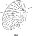
Figure 2 shows a rotor as may be incorporated into the compressor system. -
Figure 3A is a cross-sectional view through the rotor. -
Figure 3B shows internal details of the rotor. -
Figure 4A shows a structure which is incorporated into rotors made under this disclosure. -
Figure 4B shows a subsequent position of the rotor once exposed to heat. -
Figure 4C shows another embodiment. -
Figure 4D shows a feature. -
Figure 4E shows another embodiment. -
Figure 5A is a cross-sectional view through the rotor showing further details. -
Figure 5B is a side view of a blade showing further details. -
Figure 5C is a side view of an undeformed rotor and its hub. -
Figure 5D shows the deformation that the rotor and hub might experience. -
Figure 6 schematically shows a method of manufacturing the rotor. -
Figure 7 shows a distinct embodiment. -
Figure 1 shows afan system 20. Asource 10 delivers gas to aninlet 11 in afan housing 22. The gas may be air. The air approaches arotor 26 having ahub 100 with an outer surface at 28. A plurality offan blades 30 have a leadingedge 32 and atrailing edge 34. Ashroud 31surrounds rotor 26. Adiffuser housing 38 is aft of theimpeller 26. An electric motor 47 has arotor 48 and astator 50. Therotor 48 is driven to rotate, as known, and drives ashaft 42.Shaft 42 is secured torotor 26 with a connection shown at 44, and including anut 46. Abearing 40 supports theshaft 42.Rotor 26 moves air tooutlet 36. In oneapplication source 10 is an aircraft cabin that recirculates air back into ause 12 that may be a mixing chamber where it is mixed with air from an air cycle machine. The mixed air is returned to the aircraft cabin. - As shown in
Figure 2 rotor 26 includeshub 100 andblades 30 attached to and extending outward fromhub 100. -
Figure 3A showshub 100 andblades 30 each includingexterior surface 140 that surroundslattice structure 142 in an interior ofhub 100 andblades 30.Exterior surface 140 is a solid, continuous surface.Lattice structure 142 is a varying lattice structure.Lattice structure 142 has regions with varying densities. As shown,lattice structure 142 hasfirst region 150,second region 152,third region 154,fourth region 156,fifth region 158,sixth region 160,seventh region 162, andeighth region 164 inhub 100, andninth region 166 andtenth region 168 inblades 30. The regions have different densities to provide increased stiffness at particular high density locations and lower density at other less challenging areas to reduce weight.Lattice structure 142 may vary gradually or abruptly between regions.Lattice structure 142 includesmembers 198 arranged in a 3D crisscrossing pattern withvoids 200 between the members. - As shown,
lattice structure 142 varies in density by having a varying distribution of themembers 198 andvoids 200 oflattice structure 142. In alternate embodiments,lattice structure 142 can vary in density by varying the thickness of themembers 198, by having varying geometrical configurations, and/or by varying fillet radii on joints between the members. - In the embodiment shown in
Figure 3A ,first region 150,third region 154,fifth region 158,seventh region 162,ninth region 166, andtenth region 168 have a greater density thansecond region 152,fourth region 156,sixth region 160, andeighth region 164.Rotor 26 is additively manufactured, allowinglattice structure 142 to be manufactured with different densities in different areas ofrotor 26. Any suitable additive manufacturing process (also known as a 3D printing process) can be used to manufacturerotor 26, including, for example, direct metal laser sintering, electron beam freeform fabrication, electron-beam melting, selective laser melting, or selective laser sintering.Rotor 26 can be made out of any material that can be used in an additive manufacturing process, including any of stainless steel, corrosion-resistant steel, nickel-chromium alloy, titanium, aluminum, synthetic fiber, fiberglass, composites, and combinations thereof. - Traditional rotors for rotary machines have solid cross-sections and are manufactured by forging and/or subtractive manufacturing processes, such as hogout.
Additively manufacturing rotor 26 allowslattice structure 142 to be used inrotor 26. Usinglattice structure 142 inrotor 26 allowsrotor 26 to have a reduced weight compared to traditional rotors, as there arevoids 200 between the lattice structure. At the same time,rotor 26 will have an equivalent strength as traditional rotors due to the increased strength oflattice structure 142. - Further, the density of
lattice structure 142 is varied to optimize mechanical properties ofrotor 26 locally and generally. Mechanical properties ofrotor 26, such as stress, strain, and stiffness can be optimized to improve the performance ofrotor 26 by reducing stress in high stress regions ofrotor 26 and reducing strain and increasing stiffness in deflection regions ofrotor 26. Reducing stress and strain in local regions ofrotor 26 can also reduce stress and strain inrotor 26 generally. Reducing the stresses in high stress regions can reduce the failure rate ofrotor 26 and, thus, the failure rate ofcabin air compressor 10. Reduced failure rates result in reduced down time, reduced repairs, and reduced costs. Reducing the strain and increasing the stiffness in deflection regions can reduce the tolerances betweenblades 30 ofrotor 26 andshroud 31. - Reducing the tolerances between
blades 30 ofrotor 26 andshroud 31 increases the compression efficiency ofcabin air compressor 10, as more air is forced throughrotor 26 and intodiffuser 38. -
Figure 3B shows thelattice structure 142 having crossingmembers 198 creating thevoids 200 between the members. - A rotor formed with the above structure is disclosed and claimed in
United States Patent Application Serial No. 17/472,121, entitled "TURBOMACHINERY ROTOR WITH VARIABLE LATTICE DENSITIES" and filed on September 10, 2021 - While a rotor having the lattice structure as set forth above does have good qualities with regard to resisting stresses and strains, there are other features that could be improved.
Figure 4A shows aportion 101 of a rotor such asrotor 26.Portion 101 is formed of at least twometals material 104 has a larger thermal expansion coefficient than doesmaterial 102. As shown inFigure 4A , when thesection 101 is cool the edges of theportion 101 may be straight as shown at 106. - However, when exposed to heat, the
side 104 will expand to a greater length than does theside 102. As an example, inFigure 4A each of thematerial portions Figure 4B has a length L2x for theside 102 which is less than the length L2 of theside 104. As shown, this causes theportion 101 to bend as shown atcurve 108. By incorporating two materials at particular portions of the rotor, the impact of forces during operation on the rotor can be reduced by causing controlled bending. -
Figure 4C shows anapplication 110 which may be utilized in practice wherein there are a plurality of the sandwichedportions 112. Each of the sandwichedportions 112 are in contact with another sandwich portion, and alternate betweenmaterials - While the
layers Figure 4D shows this schematically, with there being outer portions that arepure material -
Figure 4E shows a portion embodiment 90 having three types ofmetals material 103 might be selected to be intermediate that ofmaterials -
Figure 5A shows therotor 26 having ablade 30, a shroud and a "fuse" 130. Thefuse 130 is selected such that upon extreme rotational stress the fuse may fracture rather than allowing the compressor to begin rotating at an undesirably high speed. Theshroud 31 will catch the fractured rotor portion. By utilizing the dual metals one can tailor the fuse such that it can be controlled to fracture at an accurate force or speed. -
Figure 5B shows ablade 30 havingmaterials blade tip 99 may be urged to bend to the left as shown in this Figure such as due to centrifugal forces F. By utilizing thematerial 102 on the opposed side, theblade tip 99 will tend to bend to the right as shown in this Figure and the impact of the force F will thus be reduced. -
Figure 5C shows anundeformed rotor 150 having ahub 152 andblades 154. When undergoing rotation, the hub will tend to deflect in a direction towards theblades 154 as illustrated inFigure 5D . Utilizing thelayers - The features shown in
Figures 5B and 5C will result in clearances between the rotor and surrounding housings and seals as designed. -
Figure 6 shows a method of utilizing additive manufacturing to form a rotor according to this disclosure. Anintermediate portion 201 hassections material 102. Anadditive manufacturing tool 208 is shown laying down material to form theintermediate section 206.Intermediate section 206 may be formed of thematerial 104. This is of course a simplification of the process; however, additive manufacturing processes are known. In embodiments, laser powder fusion additive manufacturing may be used. - Additive manufacturing involves
manufacturing rotor 26 layer by layer. Additive manufacturing processes allow complex internal and external shapes and geometries to be manufactured that are not feasible or possible with traditional manufacturing. A typical additive manufacturing process involves using a computer to create a three-dimensional representation ofrotor 26. The three-dimensional representation will be converted into instructions which dividerotor 26 into many individual layers. These instructions are then sent to an additive manufacturing device. This additive manufacturing device will print each layer, in order, and one at a time until all layers have been printed. Any additive manufacturing process can be used, including direct metal laser sintering, electron beam freeform fabrication, electron-beam melting, selective laser melting, selective laser sintering, or other equivalents that are known in the art. - The metal powders can be made of a material selected from the group consisting of stainless steel, corrosion-resistant steel, nickelchromium alloy, titanium, aluminum, and combinations thereof. This powder may be laid down by a roller, pressurized gas, or other equivalents (collectively tool 208) that are known in the art. This powder may have any grain size, wherein the grain size of the powder affects the unprocessed surface properties of
rotor 26. - A portion of the layer of
powder rotor 26. - While the application has been specifically disclosed to a compressor rotor having lattice structure, the broader idea of utilizing the differing coefficients of thermal expansion could apply to rotors for other application. Also, while the
specific rotor 26 is shown to have hollow lattice structure, other hollow structures, such as ribs, may be utilized in a rotor that benefits from this disclosure. In fact, benefits of this disclosure might extend to solid rotors. -
Figure 7 schematically shows arotor 220 wherein the rotor body is formed of a shape memory alloy. If the shape memory alloy is deformed such as illustrated inFigure 7 in a counter-clockwise direction, the shape memory will urge the rotor back to its undeformed position. The benefits of such a structure are similar to the benefits of the bi-metallic rotors disclosed above. - A rotor for a machine under this disclosure could be said to include a hub having a plurality of blades extending radially outwardly of the hub. At least one of the hub and the plurality of blades is formed of at least two metal materials. The two metal materials are selected to have different thermal expansion coefficients such that the overall rotor will be more resistant to forces it may experience as temperature or speed increases. There are layers of each of the two metal materials, with an intermediate gradient wherein the two materials are mixed.
- A rotor for a machine under another embodiment could be said to include a hub having a plurality of blades extending radially outwardly of the hub. At least one of the hub and the plurality of blades are formed of a shape memory alloy, such that the at least one of the hub and the plurality of blades resist deformation as the rotor is exposed to an increased temperature or speed.
- A method of forming a rotor under this disclosure could be said to include the steps of laying down material in layers to form an intermediate body, and of a first metal material. A layer is formed of a second metal material in contact with a portion formed of the first metal material. The two metal materials are selected to have different thermal expansion coefficients such that the overall rotor will be more resistant to forces it may experience as temperature or speed increases. There are layers of each of the two metal materials, with an intermediate gradient wherein the two materials are mixed.
- While the rotor is shown in one application, as a fan for an aircraft cabin, other rotor applications may benefit from this disclosure. Examples may include compressor or turbine rotors. While an aviation application is disclosed, the disclosure may benefit rotor in turbomachinery, or military systems, especially those with limited cycles, such as missile systems.
- While embodiments have been disclosed, a worker of skill in this art would recognize that certain modifications would come within the scope of this disclosure. For that reason, the following claims should be studied to determine the true scope and content.
Claims (15)
- A rotor for a machine comprising:a hub having a plurality of blades extending radially outwardly of said hub;at least one of said hub and said plurality of blades is formed of at least two metal materials, the two metal materials being selected to have different thermal expansion coefficients such that the overall rotor will be more resistant to forces it may experience as temperature or speed increases, and there being layers of each of the two metal materials, with an intermediate gradient wherein the two materials are mixed.
- The rotor as set forth in claim 1, wherein an electric motor is connected to drive the motor.
- The rotor as set forth in claim 1 or 2, wherein there are voids within a body of at least one of said hub and said blades formed.
- The rotor as set forth in claim 3, wherein said voids are formed by a lattice structure, and/or
wherein said voids are formed within each of said hub and said plurality of blades. - The rotor as set forth in any preceding claim, wherein the two metal materials are utilized to form at least said plurality of blades.
- The rotor as set forth in claim 5, wherein the two metal materials are selected such that said blades bend upon exposure to heat in a direction that opposes a bending centrifugal force on the blades.
- The rotor as set forth in any preceding claim, wherein the two metal materials form at least a tip of the blades to resist deformation due to centrifugal force.
- The rotor as set forth in any preceding claim, wherein the hub is formed of the at least two metal materials positioned to resist bending of the hub in a direction towards the blades.
- The rotor as set forth in any preceding claim, wherein the two metal materials also form at least a part of said hub.
- The rotor as set forth in any preceding claim wherein the hub has a fuse that will be caused to fracture should the hub be exposed to at least one of a force, or speed that is beyond predetermined desired maximum.
- The rotor as set forth in any preceding claim, wherein there are a plurality of sandwiched portions of the at least two metal materials which are sandwiched together.
- The rotor as set forth in any preceding claim, wherein there is at least a third metal material positioned between a layer of a first metal material and said second metal material with a thermal expansion coefficient of said third metal material being intermediate the thermal expansion coefficients of the first and second metal materials, and there also being a gradient between the first and third metal materials and the second and third metal materials.
- A rotor for a machine comprising:a hub having a plurality of blades extending radially outwardly of said hub;at least one of said hub and said plurality of blades formed of a shape memory alloy, such that the at least one of the hub and the plurality of blades resist deformation as the rotor is exposed to an increased temperature or speed.
- A method of forming a rotor comprising the steps of:laying down material in layers to form an intermediate body, and of a first metal material;forming a layer of a second metal material in contact with a portion formed of the first metal material, the two metal materials being selected to have different thermal expansion coefficients such that the overall rotor will be more resistant to forces it may experience as temperature or speed increases, and there being layers of each of the two metal materials, with an intermediate gradient wherein the two materials are mixed.
- The method as set forth in claim 14, wherein there are voids formed by a lattice structure within a body of the rotor,wherein, optionally, said voids are formed within each of a hub and a plurality of blades in the rotor body, and/orwherein the two metal materials having different thermal expansion coefficients, and/orwherein there is at least a third metal material positioned between a layer of a first metal material and said second metal material with a thermal expansion coefficient of said third metal material being intermediate the thermal expansion coefficients of the first and second metal materials, and there also being a gradient between the first and third metal material and the second and third metal material.
Applications Claiming Priority (1)
| Application Number | Priority Date | Filing Date | Title |
|---|---|---|---|
| US17/570,696 US11668316B1 (en) | 2022-01-07 | 2022-01-07 | Rotor formed of multiple metals |
Publications (1)
| Publication Number | Publication Date |
|---|---|
| EP4209681A1 true EP4209681A1 (en) | 2023-07-12 |
Family
ID=84488093
Family Applications (1)
| Application Number | Title | Priority Date | Filing Date |
|---|---|---|---|
| EP22212876.1A Pending EP4209681A1 (en) | 2022-01-07 | 2022-12-12 | Rotor formed of multiple metals |
Country Status (2)
| Country | Link |
|---|---|
| US (2) | US11668316B1 (en) |
| EP (1) | EP4209681A1 (en) |
Cited By (3)
| Publication number | Priority date | Publication date | Assignee | Title |
|---|---|---|---|---|
| EP4506150A1 (en) * | 2023-07-24 | 2025-02-12 | Hamilton Sundstrand Corporation | Metal plated additively manufactured plastic acm rotors with internal thermally adaptive structure |
| US12384515B2 (en) | 2023-09-08 | 2025-08-12 | Hamilton Sundstrand Corporation | Airfoil formed of thermally adaptive materials and a thermoelectric junction |
| US12635412B2 (en) | 2023-09-08 | 2026-05-19 | Hamilton Sundstrand Corporation | Locking device formed of thermally adaptive multi-metallic material and a thermoelectric junction and method of manufacturing the same |
Families Citing this family (3)
| Publication number | Priority date | Publication date | Assignee | Title |
|---|---|---|---|---|
| US20250033283A1 (en) * | 2023-07-24 | 2025-01-30 | Hamilton Sundstrand Corporation | Metal plated additively manufactured plastic acm seal plates with internal thermally adaptive structure |
| US12162606B1 (en) * | 2023-09-08 | 2024-12-10 | Hamilton Sundstrand Corporation | Metal plated plastic ACM part with internal thermally adaptive structure |
| DE102023135028A1 (en) * | 2023-12-13 | 2025-06-18 | Rolls-Royce Solutions GmbH | Turbine wheel for a turbine, in particular a radial turbine, and turbocharger with such a turbine wheel |
Citations (7)
| Publication number | Priority date | Publication date | Assignee | Title |
|---|---|---|---|---|
| EP1612373A2 (en) * | 2004-07-02 | 2006-01-04 | Rolls-Royce Plc | Adaptable fluid-foil |
| JP2006125392A (en) * | 2004-10-12 | 2006-05-18 | Man B & W Diesel Gmbh | Impeller for radial flow compressor, and method for manufacturing the same |
| EP2090752B1 (en) * | 2008-02-14 | 2014-01-15 | United Technologies Corporation | Turbine disk component composed of a composite material and corresponding manufacturing process |
| EP3173582A1 (en) * | 2015-11-24 | 2017-05-31 | General Electric Company | Turbine airfoil with passive morphing structure |
| US20200102853A1 (en) * | 2018-09-28 | 2020-04-02 | General Electric Company | Metallic compliant tip fan blade |
| US20200182066A1 (en) * | 2018-12-11 | 2020-06-11 | United Technologies Corporation | Composite gas turbine engine component with lattice structure |
| EP2817117B1 (en) * | 2012-02-23 | 2020-08-05 | Nuovo Pignone S.r.l. | Turbo-machine impeller manufacturing |
Family Cites Families (46)
| Publication number | Priority date | Publication date | Assignee | Title |
|---|---|---|---|---|
| EP0040532A1 (en) * | 1980-05-20 | 1981-11-25 | Kenwood Manufacturing Company Limited | Construction of fan blades |
| US4619580A (en) * | 1983-09-08 | 1986-10-28 | The Boeing Company | Variable camber vane and method therefor |
| DE19654092C2 (en) * | 1996-12-23 | 2001-05-10 | Carl Pawlowsky | Device for regulating the mass flow rate of a fluid medium through a flow channel |
| US6015263A (en) * | 1998-03-31 | 2000-01-18 | Motorola, Inc. | Fluid moving device and associated method |
| US6240719B1 (en) * | 1998-12-09 | 2001-06-05 | General Electric Company | Fan decoupler system for a gas turbine engine |
| GB0216312D0 (en) * | 2002-07-12 | 2002-08-21 | Rolls Royce Plc | Frangible coupling |
| DE10253299B4 (en) * | 2002-11-15 | 2004-09-30 | Daimlerchrysler Ag | Wheel |
| ITTO20080013A1 (en) * | 2008-01-09 | 2009-07-10 | Rosati Flii S R L | VARIABLE GEOMETRY FAN AND PROCEDURE FOR THE MANUFACTURE OF THE RELATED PALLETS |
| FR2926603B1 (en) * | 2008-01-23 | 2010-03-26 | Snecma | GUIDING A TREE IN A TURBOMACHINE |
| FR2942513B1 (en) * | 2009-02-20 | 2011-05-27 | Airbus France | DAWN FOR TURBOMACHINE RECEIVER, COMPRISING A BLADE PART INCORPORATING A MECHANICAL FUSE |
| WO2012060825A1 (en) * | 2010-11-03 | 2012-05-10 | Danfoss Turbocor Compressors B.V. | Centrifugal compressor with fluid injector diffuser |
| AU2010365829A1 (en) * | 2010-12-22 | 2013-05-23 | Danfoss A/S | Variable-speed oil-free refrigerant centrifugal compressor with variable geometry diffuser |
| DE102012111154A1 (en) * | 2011-11-21 | 2013-05-23 | Ecomotors International, Inc. | Bimetallic compressor wheel and method for its manufacture |
| JP5982999B2 (en) * | 2012-05-01 | 2016-08-31 | 株式会社Ihi | Rotor blade and fan |
| US9169731B2 (en) * | 2012-06-05 | 2015-10-27 | United Technologies Corporation | Airfoil cover system |
| JP2014025472A (en) * | 2012-06-21 | 2014-02-06 | Denso Corp | Liquid circulation device |
| US9650898B2 (en) * | 2012-12-27 | 2017-05-16 | United Technologies Corporation | Airfoil with variable profile responsive to thermal conditions |
| WO2014105108A1 (en) * | 2012-12-28 | 2014-07-03 | United Technologies Corporation | Gas turbine engine component having vascular engineered lattice structure |
| EP2971551B1 (en) * | 2013-03-14 | 2019-06-12 | United Technologies Corporation | Low speed fan for gas turbine engines |
| EP2843193B1 (en) * | 2013-08-28 | 2020-08-12 | Safran Aero Boosters SA | Composite blade made by additive manufacturing and corresponding manufacturing process |
| US9868155B2 (en) * | 2014-03-20 | 2018-01-16 | Ingersoll-Rand Company | Monolithic shrouded impeller |
| JP6850607B2 (en) | 2014-05-26 | 2021-03-31 | ヌオーヴォ ピニォーネ ソチエタ レスポンサビリタ リミタータNuovo Pignone S.R.L. | Methods for Manufacturing Turbomachinery Components |
| US20160010469A1 (en) | 2014-07-11 | 2016-01-14 | Hamilton Sundstrand Corporation | Hybrid manufacturing for rotors |
| EP3215290B1 (en) | 2014-11-04 | 2021-11-24 | Dresser-Rand Company | System and method for additive manufacturing of turbomachine components |
| EP3245386B1 (en) * | 2015-01-13 | 2019-07-31 | General Electric Company | A composite airfoil with fuse architecture |
| US9982684B2 (en) | 2015-08-07 | 2018-05-29 | General Electric Company | Hybrid metal compressor blades |
| US10036254B2 (en) | 2015-11-12 | 2018-07-31 | Honeywell International Inc. | Dual alloy bladed rotors suitable for usage in gas turbine engines and methods for the manufacture thereof |
| PL3387261T3 (en) | 2015-12-09 | 2020-05-18 | Atlas Copco Airpower, Naamloze Vennootschap | Shrouded impeller made by additive manufacturing and including voids in the hub and in the shroud |
| US10557464B2 (en) * | 2015-12-23 | 2020-02-11 | Emerson Climate Technologies, Inc. | Lattice-cored additive manufactured compressor components with fluid delivery features |
| US10982672B2 (en) * | 2015-12-23 | 2021-04-20 | Emerson Climate Technologies, Inc. | High-strength light-weight lattice-cored additive manufactured compressor components |
| US10634143B2 (en) * | 2015-12-23 | 2020-04-28 | Emerson Climate Technologies, Inc. | Thermal and sound optimized lattice-cored additive manufactured compressor components |
| CN109070218B (en) * | 2016-02-25 | 2022-01-28 | 伊顿智能动力有限公司 | Additive manufactured rotor for supercharger and expander |
| US9759073B1 (en) * | 2016-02-26 | 2017-09-12 | Siemens Energy, Inc. | Turbine airfoil having near-wall cooling insert |
| US10352173B2 (en) * | 2016-03-02 | 2019-07-16 | United Technologies Corporation | Shape memory alloy variable stiffness airfoil |
| US10533558B2 (en) * | 2016-12-21 | 2020-01-14 | Saudi Arabian Oil Company | Centrifugal pump with adaptive pump stages |
| US11047387B2 (en) | 2017-09-27 | 2021-06-29 | Johnson Controls Technology Company | Rotor for a compressor |
| US11131247B2 (en) | 2018-01-30 | 2021-09-28 | General Electric Company | Additively manufactured rotating shaft |
| JP2019138444A (en) | 2018-02-15 | 2019-08-22 | 日産自動車株式会社 | Rotor and its manufacturing method |
| JP2019138443A (en) | 2018-02-15 | 2019-08-22 | 日産自動車株式会社 | Rotor and its manufacturing method |
| JP7566724B2 (en) * | 2018-04-04 | 2024-10-15 | セオドシオス・アレクサンダー | Removable mechanical circulatory support units for short-term use |
| US20190368361A1 (en) * | 2018-06-05 | 2019-12-05 | General Electric Company | Non-symmetric fan blade tip cladding |
| EP3628872B1 (en) * | 2018-09-27 | 2023-01-25 | INTEL Corporation | Volumetric resistance blowers |
| US11286807B2 (en) * | 2018-09-28 | 2022-03-29 | General Electric Company | Metallic compliant tip fan blade |
| US11015482B2 (en) * | 2018-11-27 | 2021-05-25 | Honeywell International Inc. | Containment system for gas turbine engine |
| US11821441B2 (en) * | 2019-07-23 | 2023-11-21 | Transportation Ip Holdings, Llc | System for a combined turbine and bearing case for a turbocharger |
| US12459040B2 (en) | 2019-09-18 | 2025-11-04 | Autodesk, Inc. | Hybrid additive and subtractive manufacturing |
-
2022
- 2022-01-07 US US17/570,696 patent/US11668316B1/en active Active
- 2022-12-12 EP EP22212876.1A patent/EP4209681A1/en active Pending
-
2023
- 2023-05-26 US US18/202,521 patent/US20230304506A1/en not_active Abandoned
Patent Citations (7)
| Publication number | Priority date | Publication date | Assignee | Title |
|---|---|---|---|---|
| EP1612373A2 (en) * | 2004-07-02 | 2006-01-04 | Rolls-Royce Plc | Adaptable fluid-foil |
| JP2006125392A (en) * | 2004-10-12 | 2006-05-18 | Man B & W Diesel Gmbh | Impeller for radial flow compressor, and method for manufacturing the same |
| EP2090752B1 (en) * | 2008-02-14 | 2014-01-15 | United Technologies Corporation | Turbine disk component composed of a composite material and corresponding manufacturing process |
| EP2817117B1 (en) * | 2012-02-23 | 2020-08-05 | Nuovo Pignone S.r.l. | Turbo-machine impeller manufacturing |
| EP3173582A1 (en) * | 2015-11-24 | 2017-05-31 | General Electric Company | Turbine airfoil with passive morphing structure |
| US20200102853A1 (en) * | 2018-09-28 | 2020-04-02 | General Electric Company | Metallic compliant tip fan blade |
| US20200182066A1 (en) * | 2018-12-11 | 2020-06-11 | United Technologies Corporation | Composite gas turbine engine component with lattice structure |
Cited By (3)
| Publication number | Priority date | Publication date | Assignee | Title |
|---|---|---|---|---|
| EP4506150A1 (en) * | 2023-07-24 | 2025-02-12 | Hamilton Sundstrand Corporation | Metal plated additively manufactured plastic acm rotors with internal thermally adaptive structure |
| US12384515B2 (en) | 2023-09-08 | 2025-08-12 | Hamilton Sundstrand Corporation | Airfoil formed of thermally adaptive materials and a thermoelectric junction |
| US12635412B2 (en) | 2023-09-08 | 2026-05-19 | Hamilton Sundstrand Corporation | Locking device formed of thermally adaptive multi-metallic material and a thermoelectric junction and method of manufacturing the same |
Also Published As
| Publication number | Publication date |
|---|---|
| US11668316B1 (en) | 2023-06-06 |
| US20230304506A1 (en) | 2023-09-28 |
Similar Documents
| Publication | Publication Date | Title |
|---|---|---|
| US11668316B1 (en) | Rotor formed of multiple metals | |
| CN117222517B (en) | This includes blades with structures made of composite materials and related manufacturing methods. | |
| US11225871B2 (en) | Turbine airfoil with passive morphing structure | |
| EP4148290B1 (en) | Turbomachinery shaft with variable lattice densities | |
| EP4148234B1 (en) | Turbomachinery seal plate with variable lattice densities | |
| US6190133B1 (en) | High stiffness airoil and method of manufacture | |
| CN116917202B (en) | Blades comprising structures made of composite materials and related manufacturing methods | |
| CN108868902B (en) | Component with co-bonded composite material and metal ring and method of assembling the same | |
| EP4148285A1 (en) | Turbomachinery rotor shroud with variable lattice densities | |
| EP4265913B1 (en) | Auxiliary turbomachinery weight reduction using internal engineered design | |
| US20240301892A1 (en) | Turbomachinery housing with variable lattice densities | |
| US11879355B1 (en) | Airfoil assembly with an internal reinforcement structure | |
| EP4148283A1 (en) | Turbomachinery rotor with variable lattice densities | |
| WO2015105202A1 (en) | Thrust generation device | |
| JP2016130509A (en) | Thrust generating device | |
| JPWO2015105202A1 (en) | Thrust generator | |
| JP2017125416A (en) | Thrust generator | |
| US12188374B2 (en) | Turbine engine with component having a cooling hole with a layback surface | |
| EP4726173A1 (en) | Turbine engine with a blade assembly having a dovetail |
Legal Events
| Date | Code | Title | Description |
|---|---|---|---|
| PUAI | Public reference made under article 153(3) epc to a published international application that has entered the european phase |
Free format text: ORIGINAL CODE: 0009012 |
|
| STAA | Information on the status of an ep patent application or granted ep patent |
Free format text: STATUS: THE APPLICATION HAS BEEN PUBLISHED |
|
| AK | Designated contracting states |
Kind code of ref document: A1 Designated state(s): AL AT BE BG CH CY CZ DE DK EE ES FI FR GB GR HR HU IE IS IT LI LT LU LV MC ME MK MT NL NO PL PT RO RS SE SI SK SM TR |
|
| STAA | Information on the status of an ep patent application or granted ep patent |
Free format text: STATUS: REQUEST FOR EXAMINATION WAS MADE |
|
| 17P | Request for examination filed |
Effective date: 20240111 |
|
| RBV | Designated contracting states (corrected) |
Designated state(s): AL AT BE BG CH CY CZ DE DK EE ES FI FR GB GR HR HU IE IS IT LI LT LU LV MC ME MK MT NL NO PL PT RO RS SE SI SK SM TR |
|
| STAA | Information on the status of an ep patent application or granted ep patent |
Free format text: STATUS: EXAMINATION IS IN PROGRESS |
|
| 17Q | First examination report despatched |
Effective date: 20250905 |