EP4209658B1 - Verdichter mit verdichterkomponente mit rückhaltefeder - Google Patents
Verdichter mit verdichterkomponente mit rückhaltefeder Download PDFInfo
- Publication number
- EP4209658B1 EP4209658B1 EP22214893.4A EP22214893A EP4209658B1 EP 4209658 B1 EP4209658 B1 EP 4209658B1 EP 22214893 A EP22214893 A EP 22214893A EP 4209658 B1 EP4209658 B1 EP 4209658B1
- Authority
- EP
- European Patent Office
- Prior art keywords
- compressor
- dovetail
- slot
- hole
- diameter
- Prior art date
- Legal status (The legal status is an assumption and is not a legal conclusion. Google has not performed a legal analysis and makes no representation as to the accuracy of the status listed.)
- Active
Links
Images


Classifications
-
- F—MECHANICAL ENGINEERING; LIGHTING; HEATING; WEAPONS; BLASTING
- F01—MACHINES OR ENGINES IN GENERAL; ENGINE PLANTS IN GENERAL; STEAM ENGINES
- F01D—NON-POSITIVE DISPLACEMENT MACHINES OR ENGINES, e.g. STEAM TURBINES
- F01D25/00—Component parts, details, or accessories, not provided for in, or of interest apart from, other groups
- F01D25/24—Casings; Casing parts, e.g. diaphragms, casing fastenings
- F01D25/246—Fastening of diaphragms or stator-rings
-
- F—MECHANICAL ENGINEERING; LIGHTING; HEATING; WEAPONS; BLASTING
- F01—MACHINES OR ENGINES IN GENERAL; ENGINE PLANTS IN GENERAL; STEAM ENGINES
- F01D—NON-POSITIVE DISPLACEMENT MACHINES OR ENGINES, e.g. STEAM TURBINES
- F01D5/00—Blades; Blade-carrying members; Heating, heat-insulating, cooling or antivibration means on the blades or the members
- F01D5/30—Fixing blades to rotors; Blade roots ; Blade spacers
- F01D5/3023—Fixing blades to rotors; Blade roots ; Blade spacers of radial insertion type, e.g. in individual recesses
- F01D5/303—Fixing blades to rotors; Blade roots ; Blade spacers of radial insertion type, e.g. in individual recesses in a circumferential slot
- F01D5/3038—Fixing blades to rotors; Blade roots ; Blade spacers of radial insertion type, e.g. in individual recesses in a circumferential slot the slot having inwardly directed abutment faces on both sides
-
- F—MECHANICAL ENGINEERING; LIGHTING; HEATING; WEAPONS; BLASTING
- F01—MACHINES OR ENGINES IN GENERAL; ENGINE PLANTS IN GENERAL; STEAM ENGINES
- F01D—NON-POSITIVE DISPLACEMENT MACHINES OR ENGINES, e.g. STEAM TURBINES
- F01D25/00—Component parts, details, or accessories, not provided for in, or of interest apart from, other groups
- F01D25/28—Supporting or mounting arrangements, e.g. for turbine casing
-
- F—MECHANICAL ENGINEERING; LIGHTING; HEATING; WEAPONS; BLASTING
- F01—MACHINES OR ENGINES IN GENERAL; ENGINE PLANTS IN GENERAL; STEAM ENGINES
- F01D—NON-POSITIVE DISPLACEMENT MACHINES OR ENGINES, e.g. STEAM TURBINES
- F01D11/00—Preventing or minimising internal leakage of working-fluid, e.g. between stages
- F01D11/005—Sealing means between non relatively rotating elements
- F01D11/006—Sealing the gap between rotor blades or blades and rotor
- F01D11/008—Sealing the gap between rotor blades or blades and rotor by spacer elements between the blades, e.g. independent interblade platforms
-
- F—MECHANICAL ENGINEERING; LIGHTING; HEATING; WEAPONS; BLASTING
- F01—MACHINES OR ENGINES IN GENERAL; ENGINE PLANTS IN GENERAL; STEAM ENGINES
- F01D—NON-POSITIVE DISPLACEMENT MACHINES OR ENGINES, e.g. STEAM TURBINES
- F01D5/00—Blades; Blade-carrying members; Heating, heat-insulating, cooling or antivibration means on the blades or the members
- F01D5/30—Fixing blades to rotors; Blade roots ; Blade spacers
- F01D5/3007—Fixing blades to rotors; Blade roots ; Blade spacers of axial insertion type
-
- F—MECHANICAL ENGINEERING; LIGHTING; HEATING; WEAPONS; BLASTING
- F01—MACHINES OR ENGINES IN GENERAL; ENGINE PLANTS IN GENERAL; STEAM ENGINES
- F01D—NON-POSITIVE DISPLACEMENT MACHINES OR ENGINES, e.g. STEAM TURBINES
- F01D9/00—Stators
- F01D9/02—Nozzles; Nozzle boxes; Stator blades; Guide conduits, e.g. individual nozzles
- F01D9/04—Nozzles; Nozzle boxes; Stator blades; Guide conduits, e.g. individual nozzles forming ring or sector
- F01D9/042—Nozzles; Nozzle boxes; Stator blades; Guide conduits, e.g. individual nozzles forming ring or sector fixing blades to stators
-
- F—MECHANICAL ENGINEERING; LIGHTING; HEATING; WEAPONS; BLASTING
- F05—INDEXING SCHEMES RELATING TO ENGINES OR PUMPS IN VARIOUS SUBCLASSES OF CLASSES F01-F04
- F05D—INDEXING SCHEME FOR ASPECTS RELATING TO NON-POSITIVE-DISPLACEMENT MACHINES OR ENGINES, GAS-TURBINES OR JET-PROPULSION PLANTS
- F05D2240/00—Components
- F05D2240/10—Stators
- F05D2240/11—Shroud seal segments
-
- F—MECHANICAL ENGINEERING; LIGHTING; HEATING; WEAPONS; BLASTING
- F05—INDEXING SCHEMES RELATING TO ENGINES OR PUMPS IN VARIOUS SUBCLASSES OF CLASSES F01-F04
- F05D—INDEXING SCHEME FOR ASPECTS RELATING TO NON-POSITIVE-DISPLACEMENT MACHINES OR ENGINES, GAS-TURBINES OR JET-PROPULSION PLANTS
- F05D2250/00—Geometry
- F05D2250/20—Three-dimensional
- F05D2250/23—Three-dimensional prismatic
- F05D2250/231—Three-dimensional prismatic cylindrical
-
- F—MECHANICAL ENGINEERING; LIGHTING; HEATING; WEAPONS; BLASTING
- F05—INDEXING SCHEMES RELATING TO ENGINES OR PUMPS IN VARIOUS SUBCLASSES OF CLASSES F01-F04
- F05D—INDEXING SCHEME FOR ASPECTS RELATING TO NON-POSITIVE-DISPLACEMENT MACHINES OR ENGINES, GAS-TURBINES OR JET-PROPULSION PLANTS
- F05D2250/00—Geometry
- F05D2250/20—Three-dimensional
- F05D2250/23—Three-dimensional prismatic
- F05D2250/232—Three-dimensional prismatic conical
-
- F—MECHANICAL ENGINEERING; LIGHTING; HEATING; WEAPONS; BLASTING
- F05—INDEXING SCHEMES RELATING TO ENGINES OR PUMPS IN VARIOUS SUBCLASSES OF CLASSES F01-F04
- F05D—INDEXING SCHEME FOR ASPECTS RELATING TO NON-POSITIVE-DISPLACEMENT MACHINES OR ENGINES, GAS-TURBINES OR JET-PROPULSION PLANTS
- F05D2250/00—Geometry
- F05D2250/20—Three-dimensional
- F05D2250/25—Three-dimensional helical
-
- F—MECHANICAL ENGINEERING; LIGHTING; HEATING; WEAPONS; BLASTING
- F05—INDEXING SCHEMES RELATING TO ENGINES OR PUMPS IN VARIOUS SUBCLASSES OF CLASSES F01-F04
- F05D—INDEXING SCHEME FOR ASPECTS RELATING TO NON-POSITIVE-DISPLACEMENT MACHINES OR ENGINES, GAS-TURBINES OR JET-PROPULSION PLANTS
- F05D2250/00—Geometry
- F05D2250/20—Three-dimensional
- F05D2250/29—Three-dimensional machined; miscellaneous
- F05D2250/292—Three-dimensional machined; miscellaneous tapered
-
- F—MECHANICAL ENGINEERING; LIGHTING; HEATING; WEAPONS; BLASTING
- F05—INDEXING SCHEMES RELATING TO ENGINES OR PUMPS IN VARIOUS SUBCLASSES OF CLASSES F01-F04
- F05D—INDEXING SCHEME FOR ASPECTS RELATING TO NON-POSITIVE-DISPLACEMENT MACHINES OR ENGINES, GAS-TURBINES OR JET-PROPULSION PLANTS
- F05D2260/00—Function
- F05D2260/30—Retaining components in desired mutual position
- F05D2260/38—Retaining components in desired mutual position by a spring, i.e. spring loaded or biased towards a certain position
-
- Y—GENERAL TAGGING OF NEW TECHNOLOGICAL DEVELOPMENTS; GENERAL TAGGING OF CROSS-SECTIONAL TECHNOLOGIES SPANNING OVER SEVERAL SECTIONS OF THE IPC; TECHNICAL SUBJECTS COVERED BY FORMER USPC CROSS-REFERENCE ART COLLECTIONS [XRACs] AND DIGESTS
- Y02—TECHNOLOGIES OR APPLICATIONS FOR MITIGATION OR ADAPTATION AGAINST CLIMATE CHANGE
- Y02T—CLIMATE CHANGE MITIGATION TECHNOLOGIES RELATED TO TRANSPORTATION
- Y02T50/00—Aeronautics or air transport
- Y02T50/60—Efficient propulsion technologies, e.g. for aircraft
Definitions
- the present invention relates generally to the improved retention of a turbomachine component.
- the present invention relates to a compressor comprising a component having mounting features that improve retention without causing wear.
- a gas turbine engine generally includes a compressor section, a combustion section, a turbine section, and an exhaust section.
- the compressor section progressively increases the pressure of a working fluid (e.g., air) entering the gas turbine engine and supplies this compressed working fluid to the combustion section.
- the compressed working fluid and a fuel e.g., natural gas
- the combustion gases flow from the combustion section into the turbine section where they expand to produce work.
- expansion of the combustion gases in the turbine section may rotate a rotor shaft connected, e.g., to a generator to produce electricity.
- the combustion gases then exit the gas turbine via the exhaust section.
- Typical turbomachines include both rotating components (such as rotor blades) coupled to the rotor shaft and non-rotating components (such as stator vanes or nozzles) coupled to the casing. Both the rotating components and the non-rotating components are typically removable and therefore include a suitable mounting portion that is configured to engage a complementary attachment slot in the perimeter of the rotor disk (for rotating components) or the casing (for non-rotating components).
- the slot into which the mounting portion of the rotating component is inserted may be slightly larger than the mounting portion, which facilitates installation and allows for thermal expansion of the rotating component. Accordingly, the mounting portions are designed such that movement of a full speed turbomachine keeps the rotating components loaded into the slots.
- many turbomachines are operated at partial rotational speed, which can result in an incomplete loading of the rotating components in the slots due to decreased force. Operation in this way can increase the wear and/or damage to the mounting portions of the rotating components, thereby resulting in unwanted repair shut-downs and increased maintenance costs.
- EP 1 130 217 A1 discloses a turbomachine comprising a rotor with a slot receiving a turbomachine blade, the blade comprising a dovetail received by the slot, the slot including a floor and a ceiling.
- a hole is defined in the dovetail from an inlet at the innermost surface to an end wall, the hole having a cylindrical portion and a tapered portion, wherein a mechanical spring is disposed within the hole and in contact with the floor and the end wall such that the outermost surfaces of the dovetail are forced into contact with the ceiling of the slot.
- EP 1253293 A2 relates to a fixing device for a turbine blade to the rotor of a turbine.
- US 6102664 A relates to a blading system for controlling the structural vibrations in axial-flow compressors, turbines or fans, as in aircraft engines and like turbomachines including a stator disc and a rotor disc.
- EP 2562357 A1 relates to a rotor assembly including a rotor, at least one axial slot positioned about the rim of the rotor having a first staking recess positioned therein, a blade positioned within each of the axial slots having a second staking recess positioned therein, a staking insert having a base portion and a projection extending therefrom with the base portion being disposed within the first staking recess and the projection being disposed within the second staking recess, and a shim positioned within the first staking recess adjacent to the base portion, opposite the projection, of the staking insert.
- DE 112016006189 relates to a removal method of a turbine blade and a removal device for carrying out the method and a rotor set with the removal device.
- JP S58100201 relates to blades of a rotor.
- DE 3341871 A1 relates to an axial compressor where the guide vanes are fixed in a positively locking manner to a plurality of bearing ring segments, which in their turn are guided in a circumferential annular groove of the compressor casing.
- an improved turbomachine component e.g., rotating or non-rotating
- an improved turbomachine component that allows for operation of the turbomachine at partial rotational speed without causing damage to the turbomachine component over time is desired in the art.
- a compressor of a turbomachine is provided as defined in claim 1.
- fluid may be a gas or a liquid.
- fluid communication means that a fluid is capable of flowing between the areas specified.
- upstream refers to the direction from which the fluid flows
- downstream refers to the direction to which the fluid flows.
- radially refers to the relative direction that is substantially perpendicular to an axial centerline of a particular component
- axially refers to the relative direction that is substantially parallel and/or coaxially aligned to an axial centerline of a particular component
- circumumferentially refers to the relative direction that extends around the axial centerline of a particular component.
- the approximating language may correspond to the precision of an instrument for measuring the value, or the precision of the methods or machines for constructing or manufacturing the components and/or systems.
- the approximating language may refer to being within a 1, 2, 4, 5, 10, 15, or 20 percent margin in either individual values, range(s) of values and/or endpoints defining range(s) of values.
- angle or direction such terms include within ten degrees greater or less than the stated angle or direction.
- “generally vertical” includes directions within ten degrees of vertical in any direction, e.g., clockwise or counter-clockwise.
- Coupled refers to both direct coupling, fixing, or attaching, as well as indirect coupling, fixing, or attaching through one or more intermediate components or features, unless otherwise specified herein.
- directly coupled indicates that no intervening components or features are present.
- the terms “comprises,” “comprising,” “includes,” “including,” “has,” “having” or any other variation thereof, are intended to cover a non-exclusive inclusion. For example, a process, method, article, or apparatus that comprises a list of features is not necessarily limited only to those features but may include other features not expressly listed or inherent to such process, method, article, or apparatus.
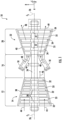
- FIG. 1 illustrates a schematic diagram of one embodiment of a turbomachine, which in the illustrated embodiment is a gas turbine 10.
- a gas turbine 10 an industrial or land-based gas turbine is shown and described herein, the present disclosure is not limited to a land-based and/or industrial gas turbine unless otherwise specified in the claims.
- the invention as described herein may be used in any type of turbomachine including but not limited to an aircraft gas turbine, or a marine gas turbine.
- the gas turbine 10 generally includes a compressor section 12 including a compressor 14 disposed at an upstream end of the gas turbine 10, a combustion section 16 having at least one combustor 18 downstream from the compressor 14, and a turbine section 20 including a turbine 22 that is downstream from the combustion section 16.
- a shaft 24 extends along an axial centerline 26 of the gas turbine 10 at least partially through the compressor 14 and/or the turbine 22.
- the shaft 24 may comprise of a plurality of individual shafts coupled to one another.
- the compressor section 12 generally includes a plurality of rotor disks 28 and a plurality of rotor blades 32 extending radially outwardly from and connected to each rotor disk 28. Each rotor disk 28 in turn is coupled to or form a portion of the shaft 24 that extends through the compressor section 12.
- the compressor section 12 further includes a compressor casing 38 that circumferentially surrounds the portion of the shaft 24 and the rotor blades 32.
- Stator vanes 33 may be mounted to the compressor casing 38.
- the rotor blades 32 and the stator vanes 33 may be arranged in an alternating manner, such that the stator vanes 33 are disposed between rotor blades 32.
- the turbine section 20 may generally include a plurality of rotor disks 27 and a plurality of rotor blades 34 extending radially outwardly from and being interconnected to each rotor disk 27. Each rotor disk 27 in turn may be coupled to or form a portion of the shaft 24 that extends through the turbine section 20.
- the turbine section 20 further includes a turbine casing 40 that circumferentially surrounds the portion of the shaft 24 and the rotor blades 34, thereby at least partially defining a hot gas path 49 through the turbine section 20.
- Stationary turbine nozzles 35 may be mounted to the turbine casing 40.
- the rotor blades 34 and stationary turbine nozzles 35 may be arranged in an alternating manner, such that the stationary turbine nozzles 35 are disposed between rotor blades 34.
- a working fluid 44 such as air is routed into the compressor 14 where it is progressively compressed in part by the rotor blades 32 as it is routed towards the combustion section 16.
- a compressed working fluid 46 flows from the compressor 14 and is supplied to the combustion section 16.
- the compressed working fluid 46 is distributed to the combustors 18 where it is mixed with a fuel (not shown) to provide a combustible mixture.
- the combustible mixture is burned to produce combustion gases 48 at a relatively high temperature and high velocity.
- the combustion gases 48 are routed through the turbine 22 where thermal and kinetic energy is transferred to the rotor blades 34, thereby causing the shaft 24 to rotate.
- the mechanical rotational energy may be used to power the compressor section 12 and/or to generate electricity.
- the shaft 24 is coupled to a generator (not shown) to produce electricity.
- the combustion gases 48 exiting the turbine section 20 may then be exhausted from the gas turbine 10 via an exhaust section.
- the compressor 14 and the turbine 22 may each includes rotating components (such as the rotor blades 32, the rotor blades 34, or others) and non-rotating or stationary components (such as the stator vanes 33, the stationary turbine nozzles 35, or others).
- the rotating components may be coupled to the rotor disks 28, 27, such that the rotating components rotate with the shaft 24.
- the non-rotating components may be coupled to the casing (e.g., the compressor casing 38 or the turbine casing 40) such that the non-rotating components are stationary during operation of the gas turbine 10.
- Both the rotating components and the non-rotating components include mounting portions configured to engage a complementary circumferential slot defined in the perimeter of the rotor disk 28, 27 (for rotating components) or casing 38, 40 (for non-rotating components).
- the mounting portions include a dovetail received by the corresponding circumferential slot.
- the circumferential slot may be defined in the casing 38, 40 for non-rotating components or the rotor disks 28, 27 for rotating components
- turbomachine component is any rotating component (e.g., rotor blades, fairings, spacers, or others) or non-rotating component (e.g., stator vanes or stationary nozzles) of the compressor 14, which has a mounting portion received by a corresponding circumferential slot defined in the rotor disk 28, 27 (for rotating components) or the casing 38, 40 (for non-rotating components).
- the turbomachine component may be a rotating component of the compressor 14.
- the gas turbine 10 may define a cylindrical coordinate system having an axial direction A extending along the axial centerline 26, a radial direction R perpendicular to the axial centerline 26, and a circumferential direction C extending around the axial centerline 26.
- a directional legend is provided for convenience in FIGS. 1 , 2 , and 4 .
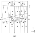
- FIG. 2 provides an enlarged cross-sectional planar view of a portion of the compressor 14.
- the compressor casing 38 generally surrounds the compressor 14 to contain a working fluid (e.g., air). Alternating stages of rotor blades 32 and stator vanes 33 arranged within the casing 38 progressively impart kinetic energy to the working fluid to produce a compressed working fluid at a highly energized state.
- Each rotor blade 32 may be circumferentially arranged around (and coupled to) the rotor disk 28 and may extend radially outward toward the casing 38.
- each stator vane 33 may be circumferentially arranged around (and coupled to) the casing 38 and may extend radially inward toward a spacer disk 29 that separates adjacent stages of rotor blades 32.
- the rotor blades 32 each include a mounting portion 57, which is formed to connect and/or to secure the rotor blade 32 to the rotor disk 28.
- the mounting portion 57 includes a dovetail.
- the mounting portion 57 may be configured to mount into the rotor disk 28 in the axial direction A, the radial direction R, and/or a circumferential direction C.
- the rotor disk 28 defines a slot 56 that generally corresponds with the shape of the mounting portion 57.
- the slot 56 may be an axial slot or opening, a radial slot or opening, and/or a circumferential slot or opening.
- the slot 56 may be defined annularly (e.g., 360° in the circumferential direction) around the entire perimeter of the rotor disk 28.
- the stator vanes 33 each include a mounting portion 59, which is formed to connect and/or to secure the stator vane 33 to the casing 38.
- the mounting portion 59 includes a dovetail.
- the mounting portion 59 may be configured to mount into the casing 38 in the axial direction A, the radial direction R, and/or a circumferential direction C.
- the casing 38 defines a slot 58 that generally corresponds with the shape of the mounting portion 59.
- the slot 58 may be an axial slot or opening, a radial slot or opening, and/or a circumferential slot or opening.
- the slot 58 may be defined annularly (e.g., 360° in the circumferential direction) around the entire perimeter of the casing 38.
- the compressor 14 may further include fairings 50 circumferentially arranged around (and coupled to) the spacer disk 29.
- the fairings 50 may extend radially outward from the spacer disk 29 to a platform 52.
- the platform 52 provides a boundary for the compressed working fluid traveling through the compressor 14.
- the platform 52 generally conforms to an inner tip 54 of the stator vanes 33 to reduce leakage between the stator vanes 33 and the spacer disks 29.
- the fairings 50 may be generally T-shaped segments.
- the fairings 50 each include a mounting portion 60, which is formed to connect and/or to secure the fairing 50 to the spacer disk 29.
- the mounting portion 60 includes a dovetail.
- the mounting portion 60 may be configured to mount into the spacer disk 29 in the axial direction A, the radial direction R, and/or a circumferential direction C.
- the spacer disk 29 defines a slot 62 that generally corresponds with the shape of the mounting portion 60.
- the slot 62 may be an axial slot or opening, a radial slot or opening, and/or a circumferential slot or opening.
- the slot 62 may be defined annularly (e.g., 360° in the circumferential direction) around the entire perimeter of the spacer disk 29.
- the mounting portions 57, 59, 60 of the various compressor components each include a mechanical spring 100 housed within a corresponding hole, void, or opening defined by the mounting portion 57, 59, 60.
- the mechanical spring 100 may be at least partially compressed in order to load the mounting portion 57, 59, 60 against the corresponding slot 56, 58, 62.
- the mechanical spring 100 may advantageously keep the compressor component loaded within the slot at any operational speed of the turbomachine (e.g., partial speed), thereby reducing wear and misalignments to the compressor component.
- compressor component may refer to one of the rotor blade 32, the stator vane 33, and/or the fairing 50. However, in exemplary embodiments, “compressor component” may refer to the fairing 50.
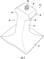
- FIG. 3 illustrates a perspective view of a turbomachine component, in accordance with embodiments of the present invention.
- FIG. 3 illustrates a perspective view of a fairing 50
- FIG. 4 illustrates an enlarged cross-sectional view of a compressor 14 having a fairing 50 coupled to a spacer disk 29.
- the fairing 50 may be generally T-shaped.
- the fairing 50 may not include an airfoil (as opposed to a rotor blade or stator vane). Instead, the fairing 50 includes a platform 52 spaced apart from, and contoured to correspond with, an inner tip 54 of the stator vane 33 (as shown in FIG. 2 ).
- the platform 52 may be the longest portion of the fairing 50 with respect to the axial direction A.
- the fairing 50 further includes a mounting portion 60 having a neck 64 and a dovetail 68.
- the neck 64 may extend radially between the platform 52 and the dovetail 68.
- the neck 64 may be the shortest portion of the fairing 50 with respect to the axial direction A (e.g., shorter axially than the platform 52 and the dovetail 68).
- the dovetail 68 may extend radially inward from, and axially outward from, the neck 64.
- the dovetail 68 may be generally shaped as a diamond or hexagon.
- the spacer disk 29 defines a slot 62 that receives the mounting portion 60 of the fairing 50.
- the slot 62 may extend radially inward into the spacer disk 29 and may extend continuously in the circumferential direction C (i.e., annularly) around the perimeter of the spacer disk 29.
- the slot 62 may be generally sized and shaped to correspond with the mounting portion 60.
- the slot 62 is defined collectively by side walls 71, 72, ceilings 75, 76, curved edges 74, and a floor 78.
- the side walls 71, 72 may be axially spaced apart from one another and may each extend generally radially (i.e., the side walls 71, 72 are generally parallel to each other).
- the side walls 71, 72 may include a first side wall 71 and a second side wall 72.
- the ceilings 75, 76 may include a first ceiling 75 that extends from the first side wall 71 and a second ceiling 76 that extends from the second side wall 72.
- the ceilings 75, 76 may each extend generally linearly between the curved edges 74 and the respective side wall 71, 72.
- the ceilings 75, 76 may each be generally oblique to both the axial direction A and the radial direction R.
- the floor 78 may extend generally axially between the curved edges 74.
- the floor 78 may be the radially innermost portion or boundary of the slot 62.
- the boundaries of the slot 62 may not include any sharp edges or angle changes, which advantageously reduces stress concentrations or risers that could otherwise result during loading of the fairing 50 onto the boundaries of the slot 62.
- "loading" may be the forced contact between two components.
- the dovetail 68 includes an inner surface 80, a first outer surface 82, and a second outer surface 84.
- the inner surface 80 may be radially spaced apart from the outer surfaces 82, 84.
- the inner surface 80 is the radially innermost surface of the dovetail 68 (and the radially innermost surface of the fairing 50), and the outer surfaces 82, 84 are the radially outermost surfaces of the dovetail 68.
- the inner surface 80 may be generally contoured to correspond with the floor 78, such that the inner surface 80 may be generally parallel to the floor 78 with a minimal gap between the floor 78 and the inner surface 80 when the mechanical spring 100 is loaded within the fairing 50.
- the first outer surface 82 may be contoured to correspond with the first ceiling 75 (e.g., generally parallel to the first ceiling), such that the first outer surface 82 may make flush or continuous contact with the first ceiling 75 when loaded.
- the second outer surface 84 may be contoured to correspond with the second ceiling 76 (e.g., generally parallel to the first ceiling), such that the second outer surface 84 may make flush or continuous contact with the second ceiling 76 when loaded.
- FIG. 5 illustrates a cross-sectional view of the fairing 50 from along the axial direction (e.g., forward looking aft), in accordance with embodiments of the present invention.
- the inner surface 80 may be generally arcuate, curved, or rounded.
- the inner surface 80 may extend generally along the circumferential direction C.
- the inner surface 80 may be generally linear in the axial direction A.
- the dovetail 68 further defines a hole 86 extending generally radially into the dovetail 68.
- the hole 86 extends from an inlet 88 at the inner surface 80 to an end wall 90.
- the end wall 90 may be disposed radially outward of the curved edges 74 of the slot 62.
- a mechanical spring 100 is disposed within the hole 86 (i.e., disposed within the dovetail 68 because the dovetail 68 defines the hole 86).
- the mechanical spring 100 may be entirely housed (or encapsulated) between the boundaries of the hole 86 and the inner surface 80.
- FIG. 6 illustrates a cross-sectional view of a dovetail 68 isolated from the slot 62 of the spacer disk
- FIG. 7 illustrates a cross-sectional view of the dovetail 68 disposed within the slot 62, in accordance with embodiments of the present invention.
- the mechanical spring 100 may be uncompressed, and in FIG. 7 , the mechanical spring 100 may be at least partially compressed.
- the mechanical spring 100 may be oriented generally radially and may be at least partially compressed between the floor 78 of the slot 62 and the end wall 90 of the hole 86, such that the outer surface(s) 82, 84 of the dovetail 68 are forced into contact with the ceiling(s) 75, 76 of the slot 62.
- the mechanical spring 100 may exert equal and opposite forces along the radial direction R.
- the mechanical spring 100 may exert a first downward force against the floor 78 and a second upward force against the end wall 90, which in turn forces the outer surface(s) 82, 84 into contact with the ceiling(s) 75, 76.
- the hole 86 may be defined along an axial centerline 94 of the dovetail 68, such that the inlet 88 is centered on the inner surface 80.
- the dovetail 68, the hole 86, and the mechanical spring 100 may each share a common axial centerline (e.g., the axial centerline 94).
- the dovetail 68, the hole 86, and the mechanical spring 100 may be coaxial, which advantageously equally distributes the forces exerted by the mechanical spring 100 and which keeps the component (e.g., fairing 50) loaded within the slot (e.g., slot 62).
- the end wall 90 may be planar.
- the end wall 90 may be entirely flat, non-curved, and/or non-contoured.
- the end wall 90 may be generally parallel to the axial direction A, generally parallel to the floor 78, and generally parallel to the inner surface 80.
- the end wall 90 being planar may advantageously allow the mechanical spring 100 to be fully seated against the end wall 90, thereby equally distributing the forces.
- the end wall 90 being planar may be particularly advantageous over, e.g., a conical end wall or curved end wall, because it prevents misalignments of the mechanical spring 100 and equally distributes the spring forces.
- the hole 86 includes cylindrical portion 96 and a tapered portion 98.
- the cylindrical portion 96 is defined by a first boundary surface 97 of the dovetail 68, and the tapered portion 98 is defined by a second boundary surface 99 of the dovetail 68.
- the tapered portion 98 extends from the inlet 88 to the cylindrical portion 96, and the cylindrical portion 96 extends from the tapered portion 98 to the end wall 90. More particularly, the tapered portion 98 may converge in diameter (or taper in diameter) along the axial centerline 94 (i.e., radially) from the inlet 88 to the cylindrical portion 96, and the cylindrical portion 96 may have a constant diameter and extend from the tapered portion 98 to the end wall 90.
- the inlet 88 defines a first diameter 102
- the cylindrical portion 96 defines a second diameter 104 (which is constant or uniform for the cylindrical portion 96).
- the first diameter 102 may be larger than the second diameter 104.
- the first diameter 102 may be between about 110% and about 140% of the second diameter 104.
- the first diameter 102 may be between about 115% and about 135% of the second diameter 104.
- the first diameter 102 may be between about 120% and about 130% of the second diameter 104.
- the hole 86 may define a total height 108 from the inlet 88 (i.e., the inner surface 80) to the end wall 90.
- the cylindrical portion 96 may define a first height 106
- the tapered portion 98 may define a second height 107 (such that a sum of the first height 106 and the second height 107 is equal to the total height 108).
- the first height 106, the second height 107, and the total height 108 may each be measured along the axial centerline 94 (i.e., radially).
- the first height 106 may be between about 40% and about 80% of the total height 108.
- the first height 106 may be between about 45% and about 75% of the total height 108.
- the first height 106 may be between about 50% and about 70% of the total height 108.
- the tapered portion 98 may be frustoconical (i.e., the shape of a frustum of a cone).
- the tapered portion 98 may linearly converge (or taper) in diameter from the first diameter 102 at the inlet 88 to the second diameter 104 at the cylindrical portion 96, such that second boundary surface 99 is straight in an axial-radial plane and generally oblique to the axial direction A and the radial direction R in the axial-radial plane.
- the first boundary surface 97 of the dovetail 68 at least partially defines the cylindrical portion 96 of the hole 86.
- the mechanical spring 100 is in contact with the first boundary surface 97, thereby ensuring the mechanical spring 100 maintains alignment within the hole 86.
- the second boundary surface 99 of the dovetail 68 at least partially defines the tapered portion 98 of the hole 86.
- the mechanical spring 100 is spaced apart (e.g., radially spaced apart) from the second boundary surface 99. In this way, the mechanical spring 100 may not contact the tapered portion 98 (or may have very limited contact with the tapered portion 98), thereby increasing hardware life of both the mechanical spring 100 and the dovetail 68 by minimizing frictional contact (i.e., wear) during operation.
- the mechanical spring 100 may be a helical spring (or coil spring).
- the mechanical spring 100 may be any one of a helical spring, a leaf spring, a wave spring, a disk spring, a spiral spring, or other spring.
- the helical spring may be a constant rate helical spring (e.g., constant spring force through compression of spring) or a progressive rate helical spring (e.g., the spring force increases while the spring is compressed).
- the increased diameter of the tapered portion 98 may advantageously prolong the life of the mechanical spring 100 and the dovetail 68 by reducing the amount of contact experienced between the mechanical spring 100 and the boundaries of the hole 86 during operation of the gas turbine 10.
- the fairing 50 may experience movements or vibrations during operation of the turbomachine, which can shift the mechanical spring 100 relative to the dovetail 68 and the slot 62.
- the cylindrical portion 96 ensures the mechanical spring 100 stays aligned within the hole 86, and the tapered portion 98 reduces the frictional contact (i.e., wear) experienced by the mechanical spring 100 and the dovetail 68, thereby prolonging the hardware life of both the mechanical spring 100 and the dovetail 68.
- the hole 86 having both a cylindrical portion 96 and a tapered portion 98 is particularly advantageous because it increases component life while maintaining alignment.
Landscapes
- Engineering & Computer Science (AREA)
- Mechanical Engineering (AREA)
- General Engineering & Computer Science (AREA)
- Structures Of Non-Positive Displacement Pumps (AREA)
Claims (7)
- Verdichter (14) einer Turbomaschine (10), der Verdichter (14) umfassend:eine oder mehrere Rotorscheiben (28, 29), die eine Welle (24) definieren;ein Gehäuse (38), das die Welle (24) umgibt;einen Schlitz (58, 56, 62), der in einem des Gehäuses (38) oder der einen oder der mehreren Rotorscheiben (28, 29) definiert ist; undeine Verdichterkomponente (33, 32, 50), die durch den Schlitz (58, 56, 62) aufgenommen ist, die Verdichterkomponente (33, 32, 50) umfassend:eine Plattform (52);einen Montageabschnitt (59, 57, 60), der sich von der Plattform (52) erstreckt, wobei der Montageabschnitt (60) einen Schwalbenschwanz (68) einschließt, der durch den Schlitz (58, 56, 62) aufgenommen wird, der in dem Verdichter (14) der Turbomaschine (10) definiert ist, wobei der Schlitz (58, 56, 62) einen Boden (78) und eine Decke (75, 76) einschließt, wobei der Schwalbenschwanz (68) umfasst:eine Innenoberfläche (80) und eine erste und eine zweite Außenoberfläche (82, 84), wobei die Innenoberfläche (80) des Schwalbenschwanzes (68) die radial innerste Oberfläche des Schwalbenschwanzes (68) ist, und die Außenoberflächen (82, 84) des Schwalbenschwanzes (68) die äußersten Oberflächen des Schwalbenschwanzes (68) sind; undein Loch (86), das in dem Schwalbenschwanz (68) von einem Einlass (88) an der Innenoberfläche (80) zu einer Endwand (90) definiert ist, wobei das Loch (86) einen zylindrischen Abschnitt (96) und einen konischen Abschnitt (98) aufweist, wobei eine mechanische Feder (100) innerhalb des Lochs (86) angeordnet ist und in Kontakt mit dem Boden (78) und der Endwand (90) steht, derart, dass die Außenoberflächen (82, 84) des Schwalbenschwanzes (68) in Kontakt mit der Decke (75, 76) des Schlitzes (62) gezwungen werden;wobei sich der konische Abschnitt (98) von dem Einlass (88) bis zu dem zylindrischen Abschnitt (96) erstreckt; wobei sich der zylindrische Abschnitt (96) von dem konischen Abschnitt (98) bis zu der Endwand (90) erstreckt;wobei eine erste Begrenzungsoberfläche (97) des Schwalbenschwanzes (68) den zylindrischen Abschnitt (96) des Lochs (86) mindestens teilweise definiert, wobei die mechanische Feder (100) in Kontakt mit der ersten Begrenzungsoberfläche (97) angeordnet ist; undwobei eine zweite Begrenzungsfläche (99) des Schwalbenschwanzes (68) den konischen Abschnitt (98) des Lochs (86) mindestens teilweise definiert, wobei die mechanische Feder (100) von der zweiten Begrenzungsoberfläche (99) beabstandet ist.
- Verdichter nach Anspruch 1, wobei der konische Abschnitt (98) eine kegelstumpfförmige Form definiert.
- Verdichter nach Anspruch 1, wobei der Einlass (88) einen ersten Durchmesser (102) definiert, wobei der zylindrische Abschnitt (96) einen zweiten Durchmesser (104) definiert, und wobei der erste Durchmesser (102) größer als der zweite Durchmesser (104) ist.
- Verdichter nach Anspruch 3, wobei der erste Durchmesser (102) zwischen etwa 110 % und etwa 140 % des zweiten Durchmessers (104) beträgt.
- Verdichter nach Anspruch 1, wobei das Loch (86) eine Gesamthöhe (108) von dem Einlass (88) bis zu der Endwand (90) definiert, wobei der zylindrische Abschnitt (96) eine erste Höhe (106) definiert, und wobei die erste Höhe (106) zwischen etwa 40 % und etwa 80 % der Gesamthöhe (108) beträgt.
- Verdichter nach Anspruch 1, wobei die mechanische Feder (100) eine Schraubenfeder ist.
- Verdichter nach Anspruch 1, wobei die Endwand (90) eben ist.
Applications Claiming Priority (1)
| Application Number | Priority Date | Filing Date | Title |
|---|---|---|---|
| IN202211000616 | 2022-01-05 |
Publications (2)
| Publication Number | Publication Date |
|---|---|
| EP4209658A1 EP4209658A1 (de) | 2023-07-12 |
| EP4209658B1 true EP4209658B1 (de) | 2024-07-31 |
Family
ID=84541372
Family Applications (1)
| Application Number | Title | Priority Date | Filing Date |
|---|---|---|---|
| EP22214893.4A Active EP4209658B1 (de) | 2022-01-05 | 2022-12-20 | Verdichter mit verdichterkomponente mit rückhaltefeder |
Country Status (4)
| Country | Link |
|---|---|
| US (1) | US11773750B2 (de) |
| EP (1) | EP4209658B1 (de) |
| JP (1) | JP2023100248A (de) |
| CN (1) | CN116412008A (de) |
Family Cites Families (14)
| Publication number | Priority date | Publication date | Assignee | Title |
|---|---|---|---|---|
| FR2282038A1 (fr) * | 1974-08-13 | 1976-03-12 | Mtu Muenchen Gmbh | Dispositif pour fixer les aubes mobiles de turbomachines |
| JPS58100201U (ja) * | 1981-12-28 | 1983-07-07 | 三菱重工業株式会社 | 軸流機械の動翼固定装置 |
| DE3341871A1 (de) * | 1983-11-19 | 1985-05-30 | Brown, Boveri & Cie Ag, 6800 Mannheim | Axialverdichter |
| US4725200A (en) | 1987-02-24 | 1988-02-16 | Westinghouse Electric Corp. | Apparatus and method for reducing relative motion between blade and rotor in steam turbine |
| US5236309A (en) | 1991-04-29 | 1993-08-17 | Westinghouse Electric Corp. | Turbine blade assembly |
| US6102664A (en) * | 1995-12-14 | 2000-08-15 | The United States Of America As Represented By The Administrator Of The National Aeronautics And Space Administration | Blading system and method for controlling structural vibrations |
| EP1130217B1 (de) * | 2000-03-01 | 2005-05-18 | ALSTOM Technology Ltd | Befestigung von Laufschaufeln in einer Turbomaschine |
| DE10120532A1 (de) * | 2001-04-26 | 2002-10-31 | Alstom Switzerland Ltd | Vorrichtung und Verfahren zur Befestigung einer Laufschaufel längs einer innerhalb eines Rotors einer axial durchströmten Turbomaschine verlaufenden Umfangsnut |
| US8616850B2 (en) | 2010-06-11 | 2013-12-31 | United Technologies Corporation | Gas turbine engine blade mounting arrangement |
| US8992180B2 (en) * | 2011-08-24 | 2015-03-31 | General Electric Company | Replaceable staking insert assembly and method |
| US9528376B2 (en) | 2012-09-13 | 2016-12-27 | General Electric Company | Compressor fairing segment |
| US9341071B2 (en) | 2013-10-16 | 2016-05-17 | General Electric Company | Locking spacer assembly |
| US9945243B2 (en) | 2014-10-14 | 2018-04-17 | Rolls-Royce Corporation | Turbine shroud with biased blade track |
| JP6641654B2 (ja) * | 2016-01-08 | 2020-02-05 | 三菱日立パワーシステムズ株式会社 | 動翼の取外方法、この方法を実行するための取外装置、この取外装置を備えるロータセット |
-
2022
- 2022-05-06 US US17/738,390 patent/US11773750B2/en active Active
- 2022-11-21 JP JP2022185385A patent/JP2023100248A/ja active Pending
- 2022-12-05 CN CN202211547570.3A patent/CN116412008A/zh active Pending
- 2022-12-20 EP EP22214893.4A patent/EP4209658B1/de active Active
Also Published As
| Publication number | Publication date |
|---|---|
| CN116412008A (zh) | 2023-07-11 |
| EP4209658A1 (de) | 2023-07-12 |
| JP2023100248A (ja) | 2023-07-18 |
| US11773750B2 (en) | 2023-10-03 |
| US20230212960A1 (en) | 2023-07-06 |
Similar Documents
| Publication | Publication Date | Title |
|---|---|---|
| US5228828A (en) | Gas turbine engine clearance control apparatus | |
| EP3181829B1 (de) | Gasturbinenmotorturbinenkühlsystem | |
| US9624784B2 (en) | Turbine seal system and method | |
| EP3835550B1 (de) | Laufschaufel für eine strömungsmaschine und strömungsmaschine | |
| CN110268174B (zh) | 具有预加载流体动力学保持架引导件的滚子元件轴承 | |
| US12281591B2 (en) | T-fairing installation tooling assembly | |
| EP4047181B1 (de) | Presspassung eines rotoraufbaus eines flugzeugmotors | |
| EP3885533B1 (de) | Laufschaufel für eine strömungsmaschine und zugehörige strömungsmaschine | |
| EP3730745B1 (de) | Rotierende blattfederdichtung | |
| EP3222811A1 (de) | Schwingungsdämpfung in einer gasturbine | |
| US9957829B2 (en) | Rotor tip clearance | |
| EP4209658B1 (de) | Verdichter mit verdichterkomponente mit rückhaltefeder | |
| CN115997066B (zh) | 用于对准密封区段的工具 | |
| US12473844B2 (en) | Module of an aircraft turbine engine | |
| US11674400B2 (en) | Gas turbine engine nozzles | |
| US20260092540A1 (en) | Support link for an exhaust diffuser assembly | |
| US11629606B2 (en) | Split-line stator vane assembly | |
| US11788424B2 (en) | Sealing ring for a wheel of a turbomachine turbine | |
| US20200141585A1 (en) | Axial stop configuration for a combustion liner | |
| US20140050558A1 (en) | Temperature gradient management arrangement for a turbine system and method of managing a temperature gradient of a turbine system |
Legal Events
| Date | Code | Title | Description |
|---|---|---|---|
| PUAI | Public reference made under article 153(3) epc to a published international application that has entered the european phase |
Free format text: ORIGINAL CODE: 0009012 |
|
| STAA | Information on the status of an ep patent application or granted ep patent |
Free format text: STATUS: THE APPLICATION HAS BEEN PUBLISHED |
|
| AK | Designated contracting states |
Kind code of ref document: A1 Designated state(s): AL AT BE BG CH CY CZ DE DK EE ES FI FR GB GR HR HU IE IS IT LI LT LU LV MC ME MK MT NL NO PL PT RO RS SE SI SK SM TR |
|
| RAP1 | Party data changed (applicant data changed or rights of an application transferred) |
Owner name: GENERAL ELECTRIC TECHNOLOGY GMBH |
|
| STAA | Information on the status of an ep patent application or granted ep patent |
Free format text: STATUS: REQUEST FOR EXAMINATION WAS MADE |
|
| 17P | Request for examination filed |
Effective date: 20240104 |
|
| RBV | Designated contracting states (corrected) |
Designated state(s): AL AT BE BG CH CY CZ DE DK EE ES FI FR GB GR HR HU IE IS IT LI LT LU LV MC ME MK MT NL NO PL PT RO RS SE SI SK SM TR |
|
| GRAP | Despatch of communication of intention to grant a patent |
Free format text: ORIGINAL CODE: EPIDOSNIGR1 |
|
| STAA | Information on the status of an ep patent application or granted ep patent |
Free format text: STATUS: GRANT OF PATENT IS INTENDED |
|
| INTG | Intention to grant announced |
Effective date: 20240426 |
|
| GRAS | Grant fee paid |
Free format text: ORIGINAL CODE: EPIDOSNIGR3 |
|
| GRAA | (expected) grant |
Free format text: ORIGINAL CODE: 0009210 |
|
| STAA | Information on the status of an ep patent application or granted ep patent |
Free format text: STATUS: THE PATENT HAS BEEN GRANTED |
|
| AK | Designated contracting states |
Kind code of ref document: B1 Designated state(s): AL AT BE BG CH CY CZ DE DK EE ES FI FR GB GR HR HU IE IS IT LI LT LU LV MC ME MK MT NL NO PL PT RO RS SE SI SK SM TR |
|
| REG | Reference to a national code |
Ref country code: CH Ref legal event code: EP Ref country code: GB Ref legal event code: FG4D |
|
| REG | Reference to a national code |
Ref country code: DE Ref legal event code: R096 Ref document number: 602022004995 Country of ref document: DE |
|
| REG | Reference to a national code |
Ref country code: NL Ref legal event code: FP Ref country code: IE Ref legal event code: FG4D |
|
| REG | Reference to a national code |
Ref country code: LT Ref legal event code: MG9D |
|
| PG25 | Lapsed in a contracting state [announced via postgrant information from national office to epo] |
Ref country code: PT Free format text: LAPSE BECAUSE OF FAILURE TO SUBMIT A TRANSLATION OF THE DESCRIPTION OR TO PAY THE FEE WITHIN THE PRESCRIBED TIME-LIMIT Effective date: 20241202 |
|
| REG | Reference to a national code |
Ref country code: AT Ref legal event code: MK05 Ref document number: 1708637 Country of ref document: AT Kind code of ref document: T Effective date: 20240731 |
|
| PG25 | Lapsed in a contracting state [announced via postgrant information from national office to epo] |
Ref country code: PT Free format text: LAPSE BECAUSE OF FAILURE TO SUBMIT A TRANSLATION OF THE DESCRIPTION OR TO PAY THE FEE WITHIN THE PRESCRIBED TIME-LIMIT Effective date: 20241202 |
|
| PG25 | Lapsed in a contracting state [announced via postgrant information from national office to epo] |
Ref country code: NO Free format text: LAPSE BECAUSE OF FAILURE TO SUBMIT A TRANSLATION OF THE DESCRIPTION OR TO PAY THE FEE WITHIN THE PRESCRIBED TIME-LIMIT Effective date: 20241031 |
|
| PG25 | Lapsed in a contracting state [announced via postgrant information from national office to epo] |
Ref country code: GR Free format text: LAPSE BECAUSE OF FAILURE TO SUBMIT A TRANSLATION OF THE DESCRIPTION OR TO PAY THE FEE WITHIN THE PRESCRIBED TIME-LIMIT Effective date: 20241101 Ref country code: FI Free format text: LAPSE BECAUSE OF FAILURE TO SUBMIT A TRANSLATION OF THE DESCRIPTION OR TO PAY THE FEE WITHIN THE PRESCRIBED TIME-LIMIT Effective date: 20240731 Ref country code: PL Free format text: LAPSE BECAUSE OF FAILURE TO SUBMIT A TRANSLATION OF THE DESCRIPTION OR TO PAY THE FEE WITHIN THE PRESCRIBED TIME-LIMIT Effective date: 20240731 |
|
| PG25 | Lapsed in a contracting state [announced via postgrant information from national office to epo] |
Ref country code: BG Free format text: LAPSE BECAUSE OF FAILURE TO SUBMIT A TRANSLATION OF THE DESCRIPTION OR TO PAY THE FEE WITHIN THE PRESCRIBED TIME-LIMIT Effective date: 20240731 |
|
| PG25 | Lapsed in a contracting state [announced via postgrant information from national office to epo] |
Ref country code: LV Free format text: LAPSE BECAUSE OF FAILURE TO SUBMIT A TRANSLATION OF THE DESCRIPTION OR TO PAY THE FEE WITHIN THE PRESCRIBED TIME-LIMIT Effective date: 20240731 |
|
| PG25 | Lapsed in a contracting state [announced via postgrant information from national office to epo] |
Ref country code: AT Free format text: LAPSE BECAUSE OF FAILURE TO SUBMIT A TRANSLATION OF THE DESCRIPTION OR TO PAY THE FEE WITHIN THE PRESCRIBED TIME-LIMIT Effective date: 20240731 Ref country code: IS Free format text: LAPSE BECAUSE OF FAILURE TO SUBMIT A TRANSLATION OF THE DESCRIPTION OR TO PAY THE FEE WITHIN THE PRESCRIBED TIME-LIMIT Effective date: 20241130 |
|
| PG25 | Lapsed in a contracting state [announced via postgrant information from national office to epo] |
Ref country code: HR Free format text: LAPSE BECAUSE OF FAILURE TO SUBMIT A TRANSLATION OF THE DESCRIPTION OR TO PAY THE FEE WITHIN THE PRESCRIBED TIME-LIMIT Effective date: 20240731 |
|
| PG25 | Lapsed in a contracting state [announced via postgrant information from national office to epo] |
Ref country code: RS Free format text: LAPSE BECAUSE OF FAILURE TO SUBMIT A TRANSLATION OF THE DESCRIPTION OR TO PAY THE FEE WITHIN THE PRESCRIBED TIME-LIMIT Effective date: 20241031 Ref country code: ES Free format text: LAPSE BECAUSE OF FAILURE TO SUBMIT A TRANSLATION OF THE DESCRIPTION OR TO PAY THE FEE WITHIN THE PRESCRIBED TIME-LIMIT Effective date: 20240731 |
|
| PG25 | Lapsed in a contracting state [announced via postgrant information from national office to epo] |
Ref country code: RS Free format text: LAPSE BECAUSE OF FAILURE TO SUBMIT A TRANSLATION OF THE DESCRIPTION OR TO PAY THE FEE WITHIN THE PRESCRIBED TIME-LIMIT Effective date: 20241031 Ref country code: PL Free format text: LAPSE BECAUSE OF FAILURE TO SUBMIT A TRANSLATION OF THE DESCRIPTION OR TO PAY THE FEE WITHIN THE PRESCRIBED TIME-LIMIT Effective date: 20240731 Ref country code: NO Free format text: LAPSE BECAUSE OF FAILURE TO SUBMIT A TRANSLATION OF THE DESCRIPTION OR TO PAY THE FEE WITHIN THE PRESCRIBED TIME-LIMIT Effective date: 20241031 Ref country code: LV Free format text: LAPSE BECAUSE OF FAILURE TO SUBMIT A TRANSLATION OF THE DESCRIPTION OR TO PAY THE FEE WITHIN THE PRESCRIBED TIME-LIMIT Effective date: 20240731 Ref country code: IS Free format text: LAPSE BECAUSE OF FAILURE TO SUBMIT A TRANSLATION OF THE DESCRIPTION OR TO PAY THE FEE WITHIN THE PRESCRIBED TIME-LIMIT Effective date: 20241130 Ref country code: HR Free format text: LAPSE BECAUSE OF FAILURE TO SUBMIT A TRANSLATION OF THE DESCRIPTION OR TO PAY THE FEE WITHIN THE PRESCRIBED TIME-LIMIT Effective date: 20240731 Ref country code: GR Free format text: LAPSE BECAUSE OF FAILURE TO SUBMIT A TRANSLATION OF THE DESCRIPTION OR TO PAY THE FEE WITHIN THE PRESCRIBED TIME-LIMIT Effective date: 20241101 Ref country code: FI Free format text: LAPSE BECAUSE OF FAILURE TO SUBMIT A TRANSLATION OF THE DESCRIPTION OR TO PAY THE FEE WITHIN THE PRESCRIBED TIME-LIMIT Effective date: 20240731 Ref country code: ES Free format text: LAPSE BECAUSE OF FAILURE TO SUBMIT A TRANSLATION OF THE DESCRIPTION OR TO PAY THE FEE WITHIN THE PRESCRIBED TIME-LIMIT Effective date: 20240731 Ref country code: BG Free format text: LAPSE BECAUSE OF FAILURE TO SUBMIT A TRANSLATION OF THE DESCRIPTION OR TO PAY THE FEE WITHIN THE PRESCRIBED TIME-LIMIT Effective date: 20240731 Ref country code: AT Free format text: LAPSE BECAUSE OF FAILURE TO SUBMIT A TRANSLATION OF THE DESCRIPTION OR TO PAY THE FEE WITHIN THE PRESCRIBED TIME-LIMIT Effective date: 20240731 |
|
| PG25 | Lapsed in a contracting state [announced via postgrant information from national office to epo] |
Ref country code: DK Free format text: LAPSE BECAUSE OF FAILURE TO SUBMIT A TRANSLATION OF THE DESCRIPTION OR TO PAY THE FEE WITHIN THE PRESCRIBED TIME-LIMIT Effective date: 20240731 Ref country code: SM Free format text: LAPSE BECAUSE OF FAILURE TO SUBMIT A TRANSLATION OF THE DESCRIPTION OR TO PAY THE FEE WITHIN THE PRESCRIBED TIME-LIMIT Effective date: 20240731 Ref country code: RO Free format text: LAPSE BECAUSE OF FAILURE TO SUBMIT A TRANSLATION OF THE DESCRIPTION OR TO PAY THE FEE WITHIN THE PRESCRIBED TIME-LIMIT Effective date: 20240731 |
|
| PG25 | Lapsed in a contracting state [announced via postgrant information from national office to epo] |
Ref country code: EE Free format text: LAPSE BECAUSE OF FAILURE TO SUBMIT A TRANSLATION OF THE DESCRIPTION OR TO PAY THE FEE WITHIN THE PRESCRIBED TIME-LIMIT Effective date: 20240731 |
|
| PG25 | Lapsed in a contracting state [announced via postgrant information from national office to epo] |
Ref country code: CZ Free format text: LAPSE BECAUSE OF FAILURE TO SUBMIT A TRANSLATION OF THE DESCRIPTION OR TO PAY THE FEE WITHIN THE PRESCRIBED TIME-LIMIT Effective date: 20240731 |
|
| PG25 | Lapsed in a contracting state [announced via postgrant information from national office to epo] |
Ref country code: SK Free format text: LAPSE BECAUSE OF FAILURE TO SUBMIT A TRANSLATION OF THE DESCRIPTION OR TO PAY THE FEE WITHIN THE PRESCRIBED TIME-LIMIT Effective date: 20240731 Ref country code: IT Free format text: LAPSE BECAUSE OF FAILURE TO SUBMIT A TRANSLATION OF THE DESCRIPTION OR TO PAY THE FEE WITHIN THE PRESCRIBED TIME-LIMIT Effective date: 20240731 |
|
| REG | Reference to a national code |
Ref country code: DE Ref legal event code: R097 Ref document number: 602022004995 Country of ref document: DE |
|
| PLBE | No opposition filed within time limit |
Free format text: ORIGINAL CODE: 0009261 |
|
| STAA | Information on the status of an ep patent application or granted ep patent |
Free format text: STATUS: NO OPPOSITION FILED WITHIN TIME LIMIT |
|
| PG25 | Lapsed in a contracting state [announced via postgrant information from national office to epo] |
Ref country code: MC Free format text: LAPSE BECAUSE OF FAILURE TO SUBMIT A TRANSLATION OF THE DESCRIPTION OR TO PAY THE FEE WITHIN THE PRESCRIBED TIME-LIMIT Effective date: 20240731 |
|
| 26N | No opposition filed |
Effective date: 20250501 |
|
| PG25 | Lapsed in a contracting state [announced via postgrant information from national office to epo] |
Ref country code: LU Free format text: LAPSE BECAUSE OF NON-PAYMENT OF DUE FEES Effective date: 20241220 |
|
| PG25 | Lapsed in a contracting state [announced via postgrant information from national office to epo] |
Ref country code: SE Free format text: LAPSE BECAUSE OF FAILURE TO SUBMIT A TRANSLATION OF THE DESCRIPTION OR TO PAY THE FEE WITHIN THE PRESCRIBED TIME-LIMIT Effective date: 20240731 |
|
| REG | Reference to a national code |
Ref country code: BE Ref legal event code: MM Effective date: 20241231 |
|
| PG25 | Lapsed in a contracting state [announced via postgrant information from national office to epo] |
Ref country code: BE Free format text: LAPSE BECAUSE OF NON-PAYMENT OF DUE FEES Effective date: 20241231 |
|
| PG25 | Lapsed in a contracting state [announced via postgrant information from national office to epo] |
Ref country code: FR Free format text: LAPSE BECAUSE OF NON-PAYMENT OF DUE FEES Effective date: 20241231 |
|
| PG25 | Lapsed in a contracting state [announced via postgrant information from national office to epo] |
Ref country code: IE Free format text: LAPSE BECAUSE OF NON-PAYMENT OF DUE FEES Effective date: 20241220 |
|
| PGFP | Annual fee paid to national office [announced via postgrant information from national office to epo] |
Ref country code: NL Payment date: 20251119 Year of fee payment: 4 |
|
| PGFP | Annual fee paid to national office [announced via postgrant information from national office to epo] |
Ref country code: DE Payment date: 20251126 Year of fee payment: 4 |