EP4209565A1 - Ceramic scintillator, photon counting-type x-ray detector, and ceramic scintillator manufacturing method - Google Patents
Ceramic scintillator, photon counting-type x-ray detector, and ceramic scintillator manufacturing method Download PDFInfo
- Publication number
- EP4209565A1 EP4209565A1 EP21864468.0A EP21864468A EP4209565A1 EP 4209565 A1 EP4209565 A1 EP 4209565A1 EP 21864468 A EP21864468 A EP 21864468A EP 4209565 A1 EP4209565 A1 EP 4209565A1
- Authority
- EP
- European Patent Office
- Prior art keywords
- ceramic scintillator
- ray
- comparative example
- light emission
- photon
- Prior art date
- Legal status (The legal status is an assumption and is not a legal conclusion. Google has not performed a legal analysis and makes no representation as to the accuracy of the status listed.)
- Granted
Links
Images


Classifications
-
- C—CHEMISTRY; METALLURGY
- C09—DYES; PAINTS; POLISHES; NATURAL RESINS; ADHESIVES; COMPOSITIONS NOT OTHERWISE PROVIDED FOR; APPLICATIONS OF MATERIALS NOT OTHERWISE PROVIDED FOR
- C09K—MATERIALS FOR MISCELLANEOUS APPLICATIONS, NOT PROVIDED FOR ELSEWHERE
- C09K11/00—Luminescent materials, e.g. electroluminescent or chemiluminescent
- C09K11/08—Luminescent materials, e.g. electroluminescent or chemiluminescent containing inorganic luminescent materials
- C09K11/77—Luminescent materials, e.g. electroluminescent or chemiluminescent containing inorganic luminescent materials containing rare earth metals
- C09K11/7766—Luminescent materials, e.g. electroluminescent or chemiluminescent containing inorganic luminescent materials containing rare earth metals containing two or more rare earth metals
-
- G—PHYSICS
- G01—MEASURING; TESTING
- G01T—MEASUREMENT OF NUCLEAR OR X-RADIATION
- G01T1/00—Measuring X-radiation, gamma radiation, corpuscular radiation, or cosmic radiation
- G01T1/16—Measuring radiation intensity
- G01T1/20—Measuring radiation intensity with scintillation detectors
- G01T1/202—Measuring radiation intensity with scintillation detectors the detector being a crystal
- G01T1/2023—Selection of materials
-
- C—CHEMISTRY; METALLURGY
- C09—DYES; PAINTS; POLISHES; NATURAL RESINS; ADHESIVES; COMPOSITIONS NOT OTHERWISE PROVIDED FOR; APPLICATIONS OF MATERIALS NOT OTHERWISE PROVIDED FOR
- C09K—MATERIALS FOR MISCELLANEOUS APPLICATIONS, NOT PROVIDED FOR ELSEWHERE
- C09K11/00—Luminescent materials, e.g. electroluminescent or chemiluminescent
- C09K11/08—Luminescent materials, e.g. electroluminescent or chemiluminescent containing inorganic luminescent materials
- C09K11/77—Luminescent materials, e.g. electroluminescent or chemiluminescent containing inorganic luminescent materials containing rare earth metals
- C09K11/7766—Luminescent materials, e.g. electroluminescent or chemiluminescent containing inorganic luminescent materials containing rare earth metals containing two or more rare earth metals
- C09K11/7774—Aluminates
-
- A—HUMAN NECESSITIES
- A61—MEDICAL OR VETERINARY SCIENCE; HYGIENE
- A61B—DIAGNOSIS; SURGERY; IDENTIFICATION
- A61B6/00—Apparatus or devices for radiation diagnosis; Apparatus or devices for radiation diagnosis combined with radiation therapy equipment
- A61B6/02—Arrangements for diagnosis sequentially in different planes; Stereoscopic radiation diagnosis
- A61B6/03—Computed tomography [CT]
-
- G—PHYSICS
- G01—MEASURING; TESTING
- G01T—MEASUREMENT OF NUCLEAR OR X-RADIATION
- G01T1/00—Measuring X-radiation, gamma radiation, corpuscular radiation, or cosmic radiation
- G01T1/16—Measuring radiation intensity
- G01T1/161—Applications in the field of nuclear medicine, e.g. in vivo counting
-
- G—PHYSICS
- G01—MEASURING; TESTING
- G01T—MEASUREMENT OF NUCLEAR OR X-RADIATION
- G01T1/00—Measuring X-radiation, gamma radiation, corpuscular radiation, or cosmic radiation
- G01T1/16—Measuring radiation intensity
- G01T1/20—Measuring radiation intensity with scintillation detectors
-
- G—PHYSICS
- G01—MEASURING; TESTING
- G01T—MEASUREMENT OF NUCLEAR OR X-RADIATION
- G01T1/00—Measuring X-radiation, gamma radiation, corpuscular radiation, or cosmic radiation
- G01T1/29—Measurement performed on radiation beams, e.g. position or section of the beam; Measurement of spatial distribution of radiation
- G01T1/2914—Measurement of spatial distribution of radiation
- G01T1/2985—In depth localisation, e.g. using positron emitters; Tomographic imaging (longitudinal and transverse section imaging; apparatus for radiation diagnosis sequentially in different planes, steroscopic radiation diagnosis)
-
- G—PHYSICS
- G01—MEASURING; TESTING
- G01T—MEASUREMENT OF NUCLEAR OR X-RADIATION
- G01T3/00—Measuring neutron radiation
- G01T3/06—Measuring neutron radiation with scintillation detectors
-
- G—PHYSICS
- G21—NUCLEAR PHYSICS; NUCLEAR ENGINEERING
- G21K—HANDLING OF PARTICLES OR IONISING RADIATION NOT OTHERWISE PROVIDED FOR; IRRADIATION DEVICES; GAMMA RAY OR X-RAY MICROSCOPES
- G21K4/00—Conversion screens for the conversion of the spatial distribution of X-rays or particle radiation into visible images, e.g. fluoroscopic screens
-
- A—HUMAN NECESSITIES
- A61—MEDICAL OR VETERINARY SCIENCE; HYGIENE
- A61B—DIAGNOSIS; SURGERY; IDENTIFICATION
- A61B6/00—Apparatus or devices for radiation diagnosis; Apparatus or devices for radiation diagnosis combined with radiation therapy equipment
- A61B6/02—Arrangements for diagnosis sequentially in different planes; Stereoscopic radiation diagnosis
- A61B6/03—Computed tomography [CT]
- A61B6/032—Transmission computed tomography [CT]
-
- A—HUMAN NECESSITIES
- A61—MEDICAL OR VETERINARY SCIENCE; HYGIENE
- A61B—DIAGNOSIS; SURGERY; IDENTIFICATION
- A61B6/00—Apparatus or devices for radiation diagnosis; Apparatus or devices for radiation diagnosis combined with radiation therapy equipment
- A61B6/42—Arrangements for detecting radiation specially adapted for radiation diagnosis
- A61B6/4208—Arrangements for detecting radiation specially adapted for radiation diagnosis characterised by using a particular type of detector
- A61B6/4233—Arrangements for detecting radiation specially adapted for radiation diagnosis characterised by using a particular type of detector using matrix detectors
-
- A—HUMAN NECESSITIES
- A61—MEDICAL OR VETERINARY SCIENCE; HYGIENE
- A61B—DIAGNOSIS; SURGERY; IDENTIFICATION
- A61B6/00—Apparatus or devices for radiation diagnosis; Apparatus or devices for radiation diagnosis combined with radiation therapy equipment
- A61B6/42—Arrangements for detecting radiation specially adapted for radiation diagnosis
- A61B6/4208—Arrangements for detecting radiation specially adapted for radiation diagnosis characterised by using a particular type of detector
- A61B6/4241—Arrangements for detecting radiation specially adapted for radiation diagnosis characterised by using a particular type of detector using energy resolving detectors, e.g. photon counting
-
- A—HUMAN NECESSITIES
- A61—MEDICAL OR VETERINARY SCIENCE; HYGIENE
- A61B—DIAGNOSIS; SURGERY; IDENTIFICATION
- A61B6/00—Apparatus or devices for radiation diagnosis; Apparatus or devices for radiation diagnosis combined with radiation therapy equipment
- A61B6/42—Arrangements for detecting radiation specially adapted for radiation diagnosis
- A61B6/4291—Arrangements for detecting radiation specially adapted for radiation diagnosis the detector being combined with a grid or grating
-
- G—PHYSICS
- G21—NUCLEAR PHYSICS; NUCLEAR ENGINEERING
- G21K—HANDLING OF PARTICLES OR IONISING RADIATION NOT OTHERWISE PROVIDED FOR; IRRADIATION DEVICES; GAMMA RAY OR X-RAY MICROSCOPES
- G21K4/00—Conversion screens for the conversion of the spatial distribution of X-rays or particle radiation into visible images, e.g. fluoroscopic screens
- G21K2004/06—Conversion screens for the conversion of the spatial distribution of X-rays or particle radiation into visible images, e.g. fluoroscopic screens with a phosphor layer
Definitions
- An embodiment of the preset invention relates to a ceramic scintillator, a photon-counting type X-ray detector, and a method for producing the ceramic scintillator.
- Imaging systems using radiation for example, X-rays are widely used in industrial applications such as baggage inspection and nondestructive inspection, and in medical applications such as X-ray diagnostic equipment and X-ray CT (Computed Tomography) equipment.
- Current mainstream imaging systems using X-rays are of an energy integration type, and generally have a configuration in which a light-emitting material and a photodetector are combined.
- Photon-counting type X-ray detectors employing a photon-counting method has been advanced. Photon-counting type X-ray detectors are also called photon detectors or photon-counting type detectors.
- the photon-counting method is characterized in that pulse signal processing is performed for incident X-ray photons one by one.
- Photon-counting methods are classified into a direct type that uses a semiconductor such as CdTe to convert X-rays directly into electrical signals, and an indirect type that converts X-rays into light with a light-emitting material and converts the light into electrical signals using a photodetector.
- the direct type can measure X-ray photon energy from the number of carriers
- the indirect type can measure the X-ray photon energy from the number of emission photons, and since it is easy to remove noise components, data with a high S/N ratio can be obtained. Due to these advantages, realization of K absorption edge imaging using contrast agents other than iodine and reduction of exposure dose due to low dose measurement is expected in medical applications.
- the mainstream of research and development in the photon-counting method is the direct type that can obtain high energy resolution.
- it is a problem of the direct type that manufacturing large-area detectors is difficult, because semiconductor materials such as CdTe are expensive, and it is difficult to obtain uniform characteristics.
- photoelectron multiplier tubes having high multiplication factors are generally used.
- the indirect type has problems that the shape of the photoelectron multiplier tube is large and that pixel configuration with a narrow gap is difficult.
- a silicon photomultiplier (Si-PM) that is a Si-based photodetector that operates in the Geiger mode, and has recently been developed solves the problems of the photoelectron multiplier tube described above, has a multiplication factor close to that of photoelectron multiplier tubes, and is low cost. Therefore, in the indirect type, it is expected that the use of silicon photomultipliers will expand in the future.
- the problem to be solved by the present invention is to provide a ceramic scintillator that can handle with a high counting rate, a photon-counting type X-ray detector, and a method for manufacturing the ceramic scintillator.
- a ceramic scintillator according to the present embodiment has a composition represented by (Lu 1-x Pr x ) a (Al 1-y Ga y ) b O 12 , wherein x, y, a, and b in the composition respectively satisfy
- Each of divisions (A) to (C) of FIG. 1 is a schematic view illustrating a configuration of a photon-counting type X-ray detector according to an embodiment.
- the division (A) of FIG. 1 is a top view of the photon-counting type X-ray detector according to the embodiment.
- the division (B) of FIG. 1 is a side view illustrating a channel direction CH of the photon-counting type X-ray detector according to the embodiment.
- the division (C) of FIG. 1 is a side view illustrating a slice direction SL of the photon-counting type X-ray detector according to the embodiment.
- Each of the divisions (A) to (C) of FIG. 1 illustrates a photon-counting type X-ray detector (hereinafter, simply referred to as an "X-ray detector") 1 according to the embodiment.
- Each of the divisions (B) and (C) of FIG. 1 illustrates a collimator device 3 in addition to the X-ray detector 1.
- the division (C) of FIG. 1 illustrates an X-ray tube 2 in addition to the X-ray detector 1.
- the X-ray detector 1 is installed on a rotating frame of a holding device.
- the X-ray detector 1 is provided with n (n: a plurality) of X-ray detection elements 1n.
- the X-ray detection elements 1n are arranged two-dimensionally in a matrix form in the channel direction and the slice direction SL.
- the channel direction means a spread direction of fan beam X-rays emitted from the X-ray tube 2
- the slice direction means a thickness direction of the fan beam X-rays.
- An X-ray incident surface of the X-ray detector 1 is formed by X-ray incident surfaces of the X-ray detection elements 1n.
- X-ray detection elements 1n For example, about 1000 X-ray detection elements 1n are arranged in the channel direction CH, and 64 X-ray detection elements 1n are arranged in the slice direction SL.
- the X-ray tube 2 is installed in a rotating frame of a holding device to face the X-ray detector 1.
- the X-ray tube 2 is a vacuum tube that generates X-rays by irradiating thermal electrons from a cathode (filament) to an anode (target) by applying a high voltage.
- a rotating anode type X-ray tube that generates X-rays by irradiating a rotating anode with thermal electrons.
- a collimator device 3 has a plurality of collimator plates having a function of absorbing scattered X-rays.
- the plurality of collimator plates comprise plates that extend in the slice direction SL and are provided to be erected to divide the X-ray detection elements 1n in the channel direction CH (one-dimensional collimator).
- the plurality of collimator plates comprise plates that extend in the slice direction SL and are provided to be erected to divide the X-ray detection elements 1n in the channel direction CH, and plates that extend in the channel direction CH and are provided to be erected to divide the X-ray detection elements 1n in the slice direction SL (two-dimensional collimator).
- An inclination of the plate surface of the collimator plate is adjusted to be parallel to an X-ray irradiation direction E that is a direction in which X-rays from an X-ray focal point F of the X-ray tube 2 are irradiated.
- the division (C) of FIG. 1 illustrates a case in which the collimator device 3 is a one-dimensional collimator. What is made by combining the collimator device 3 with the X-ray detector 1 is sometimes called a "photon-counting type X-ray detector".
- the X-ray detector 1 may be configured by arrangement of a plurality of detector modules by modularizing a predetermined number of X-ray detection elements among the X-ray detection elements 1n.
- the collimator device 3 may be configured by arrangement of a plurality of collimator modules by modularizing a predetermined number of collimator plates.
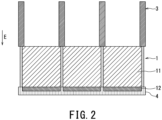
- FIG. 2 is an enlarged sectional view of a partial region R illustrated in the division (B) of FIG. 1 in the X-ray detector 1.
- the X-ray detection elements 1n are provided on a ceramic substrate 4. Each of the X-ray detection elements 1n includes a ceramic scintillator 11 and a photoelectric conversion element 12.
- the ceramic scintillator 11 is an element that converts incident X-rays into photons and emits the photons.
- X-rays usually have a predetermined X-ray energy distribution.
- An X-ray having a specific X-ray energy can be considered a mass of X-ray particles a number of which corresponds to a magnitude of the X-ray energy.
- the ceramic scintillator 11 converts the X-ray particles into photons with a predetermined probability while maintaining a mass of the X-ray particles.
- the ceramic scintillator 11 emits substantially simultaneously photon groups in number corresponding to the X-ray energy according to X-ray energy.
- the ceramic scintillator 11 is a light conversion element having a substantially rectangular parallelepiped or cubic shape.
- the ceramic scintillator 11 is disposed so that an X-ray incident surface thereof is substantially perpendicular to an X-ray irradiation direction, that is, the X-ray incident direction E, and a side surface parallel to the X-ray incident direction E is substantially parallel to the channel direction CH and the slice direction SL.
- the photoelectric conversion element 12 has a substantially plate-shaped rectangular parallelepiped shape, converts incident photons into electrical signals, and outputs the electrical signals.
- the electrical signals are electrical pulse signals corresponding to the individual incident photons.
- the photoelectric conversion element 12 outputs a pulse signal a wave height of which corresponds to a number of photons configuring the photon group.
- the photoelectric conversion element 12 is a semiconductor device suitable for so-called photon counting, and is, for example, a silicon photomultiplier (Si-PM).
- Si-PM silicon photomultiplier
- a silicon photomultiplier is a high-performance semiconductor photon detector that is capable of photon counting (photon counting) measurement, and is also applicable to analogue measurement such as scintillation detection.
- a silicon photomultiplier is an element in which a large number of pixels of avalanche photodiodes (APD) that operate in the Geiger mode are connected in parallel.
- APD avalanche photodiodes
- the photoelectric conversion element 12 receives photons emitted from the ceramic scintillator 11, and outputs electrical signals in a pulse form.
- intensity of transmission X-rays of an object is sufficiently low, the photon groups according to X-ray energy are released in a scattered state in a time axis direction, in the ceramic scintillator 11.
- the photoelectric conversion element 12 outputs, for each X-ray energy, a pulse signal having a wave height corresponding to the magnitude of the X-ray energy in numbers corresponding to a dose of the X-rays having the X-ray energy, in a state dispersed in the time axis direction.
- the pulse signals outputted in a fixed time are counted for each wave height, it is possible to know a dose of transmission X-rays of the object for each X-ray energy. If all the pulse signals outputted in a fixed time are counted regardless of wave heights, it is possible to know a dose of all transmission X-rays of the object.
- conductor patterns (not illustrated) formed on the ceramic substrate 4 are respectively connected.
- the electrical signals from the photoelectric conversion element 12 are outputted to an external processing device (not illustrated) through these conductor patterns.
- the electrical signals outputted from the photoelectric conversion element 12 are used in collection of projection data by a photon-counting method.
- a detector used in the photon-counting method generally has a very high X-ray detection sensitivity.
- the detector has high sensitivity, that is, can obtain signals with sufficient S/N, even if the dose of X-rays is low, and a number of photons emitted from the scintillator is small.
- pile-up pile-up
- the counting rate indicates the number of incident X-ray photons per unit area per unit time.
- a detector handling with a high counting rate is necessary.
- a counting rate required in X-ray CT equipment is 10 7 [cps/mm 2 ] or more. This means that X-ray photons are incident at intervals of 100 [nsec] on average.
- a scintillator capable of handling with such a high counting rate has not been put into practical use.
- the counting rate of a scintillator is mainly determined by a response speed of the material. Therefore, there is an urgent need to develop materials for scintillators with improved response speeds so as not to cause pile-up while avoiding long-time measurements.
- a main factor that determines the response speed of the indirect type is a decay time constant of light emission of a scintillator.
- control of the decay time constant of light emission of the scintillator becomes particularly important, and the decay time constant of light emission needs to be about 15 [nsec] or less.
- the decay time constant of light emission 15 [nsec] or less, it becomes possible to prevent pile-up and realize imaging at a practical level as described above.
- experiments were conducted with an aim of setting the decay time constant of light emission of the scintillator to about 15 [nsec] or less.
- a relative light yield of 30 [%] or more is good. This is because if the relative light yield is 30 [%] or more, there is no problem in both the S/N ratio and the energy resolution, and a detector with higher accuracy can be obtained.
- a fluorescent material of the ceramic scintillator 11 that is applied as the light conversion element has a composition represented by
- the fluorescent materials according to examples 1 to 52 are produced through the following steps. First, in a first step, powder of a mixture (mixture of oxide powders of Lu, Pr, Al, and Ga) of lutetium oxide, praseodymium oxide, alumina, and gallium oxide is filled in an alumina container and fired at a temperature of 1300°C or higher.
- the product obtained in the first step is filled in an alumina container and is fired at a temperature of 1200°C or higher in a nitrogen-hydrogen mixed atmosphere.
- the product obtained by the second step is molded.
- the product obtained by the third step is fired, and thereby each of the fluorescent materials is produced.
- Sintering is done in one step.
- sintering in one step, unlike the case of performing sintering in two steps or more, it is possible to obtain a scintillator that has little deviation in composition and good crystallinity, and has a small decay time constant because it can suppress volatilization of Ga.
- the fluorescent materials comprise elements contained in the above-described composition, and do not contain any other elements except for unavoidable impurities. This is because the decay time constant of light emission changes depending on the contained elements, and therefore when a large amount of impurities is contained, the decay time constant of light emission may increase.
- impurities such as Si, Fe, Ca, and Mg that are contained in a raw material, a sintering aid and the like are several tens of ppm or less. Impurities of 100 ppm or more may be included as long as they comply with the required relative light yield and/or the required decay time constant of light emission.
- variables x and y in the composition of (Lu 1-x Pr x ) a (Al 1-y Ga y ) b O 12 will be described by using Table 4 and Table 5.
- a decay time constant ⁇ [nsec] of fluorescence is obtained as a time until light emission intensity decays to 1/e after X-rays are generated by using a pulse X-ray tube, each of the fluorescent materials are irradiated with the X-rays, and irradiation of X-rays is stopped.
- the decay time constant ⁇ generally has two or more components.
- the decay time constant described in each of the examples and comparative examples is a weighted average value calculated from two components and calculated from an intensity ratio thereof.
- compositions of the fluorescent materials according to examples 1 to 38 shown in Table 2 satisfy 0.005 ⁇ x ⁇ 0.025, and 0.3 ⁇ y ⁇ 0.7.
- compositions of the fluorescent materials according to comparative examples 1 to 42 shown in Table 3 do not satisfy 0.005 ⁇ x ⁇ 0.025, or 0.3 ⁇ y ⁇ 0.7, unlike the compositions of the fluorescent materials according to examples 1 to 38 shown in Table 2.
- Example 1 0.005 0.30 150 15
- Example 2 0.006 0.30 155 15
- Example 3 0.010 0.30 165 14
- Example 4 0.013 0.30 80 13
- Example 5 0.016 0.30 70 12
- Example 6 0.020 0.30 68 10
- Example 7 0.025 0.30 65 10
- Example 8 0.005 0.40 165 15
- Example 9 0.006 0.40 174 15
- Example 10 0.010 0.40 185 15
- Example 11 0.013 0.40 87 12
- Example 12 0.016 0.40 79 11
- Example 13 0.020 0.40 75 10
- Example 14 0.025 0.40 71 9
- Example 15 0.005 0.50 95 12
- Example 17 0.010 0.50 139 11
- Example 18 0.013 0.50 70 8
- Example 19 0.016 0.50 66 8
- Example 20 0.020 0.50 66 7
- Example 21 0.025 0.50 60 7
- Example 22 0.005 0.55 74 12
- FIG. 3 is a diagram showing characteristics in the fluorescent materials of examples 1 to 38 and the fluorescent materials of comparative examples 1 to 42 as correspondence tables.
- a division (A) of FIG. 3 shows a relative light yield as characteristics of the fluorescent materials.
- a division (B) of FIG. 3 shows the decay time constant of the light emission as the characteristics of the fluorescent materials.
- the relative light yield is 30[%] or more.
- a peak of the relative light yield that is, a high characteristic region exists.
- the decay time constants of light emission are 15 [nsec] or less.
- the division (B) of FIG. 3 it is found that as a whole, as the variables x and y become larger, that is, as Pr and Ga increase more, the decay time constant of light emission tends to be smaller.
- variable y is preferably 0.40 ⁇ y ⁇ 0.55.
- the variable y is preferably 0.40 ⁇ y ⁇ 0.55.
- the decay time constant As shown in the division (B) of FIG. 3 , it is possible to decrease the decay time constant of light emission by increasing the variable y. However, if the decay time constant is shortened by this method, there is a problem that the relative light yield is reduced, and when the variable y is 0.60 or more, the light yield tends to decrease sharply (see the division (A) of FIG. 3 ). Therefore, in order to obtain a small decay time constant while maintaining a certain amount of light emission, 0.40 ⁇ y ⁇ 0.55 is preferable.
- variables a and b in the composition of (Lu 1-x Pr x ) a (Al 1-y Ga y ) b O 12 will be described by using Table 4 and Table 5.
- the decay time constant ⁇ [nsec] of fluorescence is obtained as a time until the light emission intensity decays to 1/e after X-rays are generated by using a pulse X-ray tube, each of the fluorescent materials is irradiated with X-rays, and irradiation of X-rays is stopped.
- compositions of the fluorescent materials according to examples 39 to 52 shown in Table 4 satisfy 2.8 ⁇ a ⁇ 3.1 and 4.8 ⁇ b ⁇ 5.2.
- compositions of the fluorescent materials according to comparative examples 43 to 58 shown in Table 5 do not satisfy 2.8 ⁇ a ⁇ 3.1, or 4.8 ⁇ b ⁇ 5.2, unlike the compositions of the fluorescent materials according to examples 39 to 52 shown in Table 4.
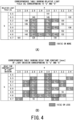
- FIG. 4 is a diagram showing characteristics in the fluorescent materials of examples 39 to 52, and the fluorescent materials of comparative examples 43 to 58 as correspondence tables.
- a division (A) of FIG. 4 shows a relative light yield as the characteristics of the fluorescent materials.
- a division (B) of FIG. 4 shows a decay time constant of light emission as the characteristics of the fluorescent materials.
- the relative light yield are 150[%] or more.
- a and b in the composition represented by (Lu 1-x Pr x ) a (Al 1-y Ga y ) b O 12 are respectively 2.8 ⁇ a ⁇ 3.1, and 4.8 ⁇ b ⁇ 5.2 (within frames of broken lines in the drawing), it is possible to control a time constant of light emission to about 150[%] or more, and the decay time constant of light emission to about 15 [nsec] or less. It goes without saying that it is possible to select the variables a and b in the composition arbitrarily according to the required relative light yield, and/or the required decay time constant of light emission.
- varying x and y as variables that is, varying a composition ratio corresponds to varying characteristics of garnet itself as the fluorescent material
- varying a and b as variables corresponds to varying characteristics due to change of a structure itself of garnet, and occurrence of defects in the garnet structure.
- a ceramic scintillator that can handle with a high counting rate, a photon-counting type X-ray detector equipped with it, and a method for manufacturing the ceramic scintillator.
- the ceramic scintillator 11 is not limited to the case of being applied to a photon-counting type X-ray detector equipped with a silicon photomultiplier, in X-ray CT equipment.
- the ceramic scintillator 11 may be applied to an X-ray detector equipped with photodiode, in X-ray CT equipment.
- the ceramic scintillator 11 may also be applied to a flat panel detector (FPD: Flat Panel Detector) equipped with CMOS (Complementary Metal Oxided Semiconductor).
- FPD Flat Panel Detector
- CMOS Complementary Metal Oxided Semiconductor
- the ceramic scintillator 11 may be applied to a photon-counting type detector equipped with a silicon photomultiplier, in PET (Positron Emission Tomography) equipment.
- the ceramic scintillator 11 may be applied to imaging for industrial applications such as baggage inspection, and a nondestructive inspection.
Landscapes
- Health & Medical Sciences (AREA)
- Life Sciences & Earth Sciences (AREA)
- Physics & Mathematics (AREA)
- High Energy & Nuclear Physics (AREA)
- Chemical & Material Sciences (AREA)
- Molecular Biology (AREA)
- Engineering & Computer Science (AREA)
- General Physics & Mathematics (AREA)
- Spectroscopy & Molecular Physics (AREA)
- Medical Informatics (AREA)
- Nuclear Medicine, Radiotherapy & Molecular Imaging (AREA)
- General Health & Medical Sciences (AREA)
- Biomedical Technology (AREA)
- Optics & Photonics (AREA)
- Organic Chemistry (AREA)
- Materials Engineering (AREA)
- Inorganic Chemistry (AREA)
- Crystallography & Structural Chemistry (AREA)
- Biophysics (AREA)
- Animal Behavior & Ethology (AREA)
- Public Health (AREA)
- Veterinary Medicine (AREA)
- Surgery (AREA)
- Heart & Thoracic Surgery (AREA)
- Radiology & Medical Imaging (AREA)
- Pathology (AREA)
- General Engineering & Computer Science (AREA)
- Luminescent Compositions (AREA)
- Measurement Of Radiation (AREA)
Abstract
Description
- An embodiment of the preset invention relates to a ceramic scintillator, a photon-counting type X-ray detector, and a method for producing the ceramic scintillator.
- Imaging systems using radiation, for example, X-rays are widely used in industrial applications such as baggage inspection and nondestructive inspection, and in medical applications such as X-ray diagnostic equipment and X-ray CT (Computed Tomography) equipment. Current mainstream imaging systems using X-rays are of an energy integration type, and generally have a configuration in which a light-emitting material and a photodetector are combined.
- However, the energy integration type has problems that X-ray energy information cannot be obtained and that the exposure dose is large. In recent years, in order to solve these problems, development of photon-counting type X-ray detectors employing a photon-counting method has been advanced. Photon-counting type X-ray detectors are also called photon detectors or photon-counting type detectors.
- The photon-counting method is characterized in that pulse signal processing is performed for incident X-ray photons one by one. Photon-counting methods are classified into a direct type that uses a semiconductor such as CdTe to convert X-rays directly into electrical signals, and an indirect type that converts X-rays into light with a light-emitting material and converts the light into electrical signals using a photodetector.
- Among the photon counting methods, the direct type can measure X-ray photon energy from the number of carriers, the indirect type can measure the X-ray photon energy from the number of emission photons, and since it is easy to remove noise components, data with a high S/N ratio can be obtained. Due to these advantages, realization of K absorption edge imaging using contrast agents other than iodine and reduction of exposure dose due to low dose measurement is expected in medical applications. The mainstream of research and development in the photon-counting method is the direct type that can obtain high energy resolution. However, it is a problem of the direct type that manufacturing large-area detectors is difficult, because semiconductor materials such as CdTe are expensive, and it is difficult to obtain uniform characteristics.
- On the other hand, in the photodetectors of the indirect type among the photon-counting methods, photoelectron multiplier tubes having high multiplication factors are generally used. However, the indirect type has problems that the shape of the photoelectron multiplier tube is large and that pixel configuration with a narrow gap is difficult. A silicon photomultiplier (Si-PM) that is a Si-based photodetector that operates in the Geiger mode, and has recently been developed solves the problems of the photoelectron multiplier tube described above, has a multiplication factor close to that of photoelectron multiplier tubes, and is low cost. Therefore, in the indirect type, it is expected that the use of silicon photomultipliers will expand in the future.
-
-
Patent Document 1Japanese Patent Laid-Open No. 2018-2974 -
Patent Document 2Japanese Patent No. 5462515 - The problem to be solved by the present invention is to provide a ceramic scintillator that can handle with a high counting rate, a photon-counting type X-ray detector, and a method for manufacturing the ceramic scintillator.
- A ceramic scintillator according to the present embodiment has a composition represented by (Lu1-xPrx)a(Al1-yGay)bO12, wherein x, y, a, and b in the composition respectively satisfy
- 0.005≤x≤0.025,
- 0.3≤y≤0.7,
- 2.8≤a≤3.1, and
- 4.8≤b≤5.2.
-
- [
FIG. 1] FIG. 1 is a schematic view illustrating a configuration of a photon-counting type X-ray detector according to an embodiment. - [
FIG. 2] FIG. 2 is an enlarged sectional view of the partial region shown in a division (B) ofFIG. 1 in the photon counting type X-ray detector according to the embodiment. - [
FIG. 3] FIG. 3 is a table showing the characteristics of the fluorescent materials of Examples 1-38 and Comparative Examples 1-42. - [
FIG. 4] FIG. 4 is a table showing the characteristics of the fluorescent materials of Examples 39 to 52 and Comparative Examples 43 to 58. - Hereinafter, embodiments of a ceramic scintillator, a photon-counting type X-ray detector, and a method for manufacturing the ceramic scintillator will be described in detail with reference to the drawings.
- Each of divisions (A) to (C) of
FIG. 1 is a schematic view illustrating a configuration of a photon-counting type X-ray detector according to an embodiment. The division (A) ofFIG. 1 is a top view of the photon-counting type X-ray detector according to the embodiment. The division (B) ofFIG. 1 is a side view illustrating a channel direction CH of the photon-counting type X-ray detector according to the embodiment. The division (C) ofFIG. 1 is a side view illustrating a slice direction SL of the photon-counting type X-ray detector according to the embodiment. - Each of the divisions (A) to (C) of
FIG. 1 illustrates a photon-counting type X-ray detector (hereinafter, simply referred to as an "X-ray detector") 1 according to the embodiment. Each of the divisions (B) and (C) ofFIG. 1 illustrates acollimator device 3 in addition to theX-ray detector 1. The division (C) ofFIG. 1 illustrates anX-ray tube 2 in addition to theX-ray detector 1. - The
X-ray detector 1 is installed on a rotating frame of a holding device. TheX-ray detector 1 is provided with n (n: a plurality) ofX-ray detection elements 1n. TheX-ray detection elements 1n are arranged two-dimensionally in a matrix form in the channel direction and the slice direction SL. The channel direction means a spread direction of fan beam X-rays emitted from theX-ray tube 2, and the slice direction means a thickness direction of the fan beam X-rays. - An X-ray incident surface of the
X-ray detector 1 is formed by X-ray incident surfaces of theX-ray detection elements 1n. For example, about 1000X-ray detection elements 1n are arranged in the channel direction CH, and 64X-ray detection elements 1n are arranged in the slice direction SL. - The
X-ray tube 2 is installed in a rotating frame of a holding device to face theX-ray detector 1. TheX-ray tube 2 is a vacuum tube that generates X-rays by irradiating thermal electrons from a cathode (filament) to an anode (target) by applying a high voltage. For example, amongX-ray tubes 2, there is a rotating anode type X-ray tube that generates X-rays by irradiating a rotating anode with thermal electrons. - A
collimator device 3 has a plurality of collimator plates having a function of absorbing scattered X-rays. The plurality of collimator plates comprise plates that extend in the slice direction SL and are provided to be erected to divide theX-ray detection elements 1n in the channel direction CH (one-dimensional collimator). Alternatively, the plurality of collimator plates comprise plates that extend in the slice direction SL and are provided to be erected to divide theX-ray detection elements 1n in the channel direction CH, and plates that extend in the channel direction CH and are provided to be erected to divide theX-ray detection elements 1n in the slice direction SL (two-dimensional collimator). An inclination of the plate surface of the collimator plate is adjusted to be parallel to an X-ray irradiation direction E that is a direction in which X-rays from an X-ray focal point F of theX-ray tube 2 are irradiated. The division (C) ofFIG. 1 illustrates a case in which thecollimator device 3 is a one-dimensional collimator. What is made by combining thecollimator device 3 with theX-ray detector 1 is sometimes called a "photon-counting type X-ray detector". - The
X-ray detector 1 may be configured by arrangement of a plurality of detector modules by modularizing a predetermined number of X-ray detection elements among theX-ray detection elements 1n. Likewise, thecollimator device 3 may be configured by arrangement of a plurality of collimator modules by modularizing a predetermined number of collimator plates. -
FIG. 2 is an enlarged sectional view of a partial region R illustrated in the division (B) ofFIG. 1 in theX-ray detector 1. - The
X-ray detection elements 1n are provided on aceramic substrate 4. Each of theX-ray detection elements 1n includes aceramic scintillator 11 and aphotoelectric conversion element 12. - The
ceramic scintillator 11 is an element that converts incident X-rays into photons and emits the photons. Here, X-rays usually have a predetermined X-ray energy distribution. An X-ray having a specific X-ray energy can be considered a mass of X-ray particles a number of which corresponds to a magnitude of the X-ray energy. Theceramic scintillator 11 converts the X-ray particles into photons with a predetermined probability while maintaining a mass of the X-ray particles. When X-rays are incident on theceramic scintillator 11, theceramic scintillator 11 emits substantially simultaneously photon groups in number corresponding to the X-ray energy according to X-ray energy. - The
ceramic scintillator 11 is a light conversion element having a substantially rectangular parallelepiped or cubic shape. Theceramic scintillator 11 is disposed so that an X-ray incident surface thereof is substantially perpendicular to an X-ray irradiation direction, that is, the X-ray incident direction E, and a side surface parallel to the X-ray incident direction E is substantially parallel to the channel direction CH and the slice direction SL. - The
photoelectric conversion element 12 has a substantially plate-shaped rectangular parallelepiped shape, converts incident photons into electrical signals, and outputs the electrical signals. The electrical signals are electrical pulse signals corresponding to the individual incident photons. When photon groups are simultaneously incident on thephotoelectric conversion element 12, thephotoelectric conversion element 12 outputs a pulse signal a wave height of which corresponds to a number of photons configuring the photon group. Thephotoelectric conversion element 12 is a semiconductor device suitable for so-called photon counting, and is, for example, a silicon photomultiplier (Si-PM). A silicon photomultiplier is a high-performance semiconductor photon detector that is capable of photon counting (photon counting) measurement, and is also applicable to analogue measurement such as scintillation detection. A silicon photomultiplier is an element in which a large number of pixels of avalanche photodiodes (APD) that operate in the Geiger mode are connected in parallel. - The
photoelectric conversion element 12 receives photons emitted from theceramic scintillator 11, and outputs electrical signals in a pulse form. When intensity of transmission X-rays of an object is sufficiently low, the photon groups according to X-ray energy are released in a scattered state in a time axis direction, in theceramic scintillator 11. At this time, thephotoelectric conversion element 12 outputs, for each X-ray energy, a pulse signal having a wave height corresponding to the magnitude of the X-ray energy in numbers corresponding to a dose of the X-rays having the X-ray energy, in a state dispersed in the time axis direction. Accordingly, if the pulse signals outputted in a fixed time are counted for each wave height, it is possible to know a dose of transmission X-rays of the object for each X-ray energy. If all the pulse signals outputted in a fixed time are counted regardless of wave heights, it is possible to know a dose of all transmission X-rays of the object. - To the
photoelectric conversion element 12, conductor patterns (not illustrated) formed on theceramic substrate 4 are respectively connected. The electrical signals from thephotoelectric conversion element 12 are outputted to an external processing device (not illustrated) through these conductor patterns. The electrical signals outputted from thephotoelectric conversion element 12 are used in collection of projection data by a photon-counting method. - Here, a detector used in the photon-counting method generally has a very high X-ray detection sensitivity. The detector has high sensitivity, that is, can obtain signals with sufficient S/N, even if the dose of X-rays is low, and a number of photons emitted from the scintillator is small. However, when the dose of X-rays is large, the pulse signals are superimposed, a phenomenon called pile-up (pile up) occurs, and it becomes impossible to resolve the signals in the time axis direction.
- Among the photon counting methods, in the case of the indirect type, there is a problem of counting rate as in the case of the direct type. The counting rate indicates the number of incident X-ray photons per unit area per unit time. In order to realize imaging by a photon-counting type X-ray detector, a detector handling with a high counting rate is necessary. For example, a counting rate required in X-ray CT equipment is 107 [cps/mm2] or more. This means that X-ray photons are incident at intervals of 100 [nsec] on average. At present, a scintillator capable of handling with such a high counting rate has not been put into practical use. If the counting rate exceeds a capacity of the scintillator, pile-up occurs, and it becomes difficult to measure correct photon energy. On the other hand, suppressing the counting rate and performing measurement for a long time causes problems such as a decrease in throughput and a decrease in time resolution.
- The counting rate of a scintillator is mainly determined by a response speed of the material. Therefore, there is an urgent need to develop materials for scintillators with improved response speeds so as not to cause pile-up while avoiding long-time measurements.
- A main factor that determines the response speed of the indirect type is a decay time constant of light emission of a scintillator. In order to realize the aforementioned counting rate 107 [cps/mm2], control of the decay time constant of light emission of the scintillator becomes particularly important, and the decay time constant of light emission needs to be about 15 [nsec] or less. By making the decay time constant of light emission 15 [nsec] or less, it becomes possible to prevent pile-up and realize imaging at a practical level as described above. Thus, experiments were conducted with an aim of setting the decay time constant of light emission of the scintillator to about 15 [nsec] or less. As a result, it was found that a relative light yield of 30 [%] or more is good. This is because if the relative light yield is 30 [%] or more, there is no problem in both the S/N ratio and the energy resolution, and a detector with higher accuracy can be obtained.
- In other words, it is desirable that the decay time constant is 15 [nsec] or less and the relative light yield is 30[%] or more. For this purpose, a fluorescent material of the
ceramic scintillator 11 that is applied as the light conversion element has a composition represented by - (Lu1-xPrx)a(Al1-yGay)bO12, wherein x, y, a, and b in the composition respectively satisfy all of
- 0.005≤x≤0.025,
- 0.3≤y≤0.7,
- 2.8≤a≤3.1, and
- 4.8≤b≤5.2.
- As a result of the experiments, it was found that there is a trade-off relationship as shown in Table 1, and if the relationship in Table 1 is further satisfied, it is possible to realize detection with higher accuracy by the detector.
[Table 1] Decay Time Constant of Light Yield Relative Light Emission Amount 15[nsec] 150[%] or more 10[nsec] or more less than 15[nsec] 65[%] or more less than 10[nsec] 30[%] or more - Subsequently, a result of producing fluorescent materials according to examples 1 to 52 (Table 2 and Table 4) having the above-described composition, and fluorescent materials according to comparative examples 1 to 58 (Table 3 and Table 5), and investigating characteristics of the relative light yield (or relative light emission intensities), and the decay time constants of light emission respectively will be described. The fluorescent materials according to examples 1 to 52, and the fluorescent materials according to comparative examples 1 to 58 are produced through the following steps. First, in a first step, powder of a mixture (mixture of oxide powders of Lu, Pr, Al, and Ga) of lutetium oxide, praseodymium oxide, alumina, and gallium oxide is filled in an alumina container and fired at a temperature of 1300°C or higher. In a second step, the product obtained in the first step is filled in an alumina container and is fired at a temperature of 1200°C or higher in a nitrogen-hydrogen mixed atmosphere. In a third step, the product obtained by the second step is molded. In a fourth step, the product obtained by the third step is fired, and thereby each of the fluorescent materials is produced.
- Sintering is done in one step. By performing sintering in one step, unlike the case of performing sintering in two steps or more, it is possible to obtain a scintillator that has little deviation in composition and good crystallinity, and has a small decay time constant because it can suppress volatilization of Ga.
- The fluorescent materials comprise elements contained in the above-described composition, and do not contain any other elements except for unavoidable impurities. This is because the decay time constant of light emission changes depending on the contained elements, and therefore when a large amount of impurities is contained, the decay time constant of light emission may increase. In each of the fluorescent materials according to examples 1 to 52 (Table 2 and Table 4) and the fluorescent materials according to comparative examples 1 to 58 (Table 3 and Table 5), impurities such as Si, Fe, Ca, and Mg that are contained in a raw material, a sintering aid and the like are several tens of ppm or less. Impurities of 100 ppm or more may be included as long as they comply with the required relative light yield and/or the required decay time constant of light emission.
- First, variables x and y in the composition of (Lu1-xPrx)a(Al1-yGay)bO12 will be described by using Table 4 and Table 5. The fluorescent materials according to examples 1 to 38 shown in Table 2 and the fluorescent materials according to comparative examples 1 to 42 shown in Table 3 were produced by varying x and y as variables while fixing a=3 and b=5, in the composition. The relative light yield in Table 2 and Table 3 were obtained by obtaining light emission intensities of the respective fluorescent materials, and converting the light emission intensities into relative values [%] in a case of the light emission intensity of x=0.002 and y=0 being taken as 100[%]. A decay time constant τ [nsec] of fluorescence is obtained as a time until light emission intensity decays to 1/e after X-rays are generated by using a pulse X-ray tube, each of the fluorescent materials are irradiated with the X-rays, and irradiation of X-rays is stopped. The decay time constant τ generally has two or more components. The decay time constant described in each of the examples and comparative examples is a weighted average value calculated from two components and calculated from an intensity ratio thereof.
- In addition, the compositions of the fluorescent materials according to examples 1 to 38 shown in Table 2 satisfy 0.005≤x≤0.025, and 0.3≤y≤0.7. On the other hand, the compositions of the fluorescent materials according to comparative examples 1 to 42 shown in Table 3 do not satisfy 0.005≤x≤0.025, or 0.3≤y≤0.7, unlike the compositions of the fluorescent materials according to examples 1 to 38 shown in Table 2.
[Table 2] a=3, b=5 x y Relative Light Yield [%] Decay Time Constant of Light Emission [nsec] Example 1 0.005 0.30 150 15 Example 2 0.006 0.30 155 15 Example 3 0.010 0.30 165 14 Example 4 0.013 0.30 80 13 Example 5 0.016 0.30 70 12 Example 6 0.020 0.30 68 10 Example 7 0.025 0.30 65 10 Example 8 0.005 0.40 165 15 Example 9 0.006 0.40 174 15 Example 10 0.010 0.40 185 15 Example 11 0.013 0.40 87 12 Example 12 0.016 0.40 79 11 Example 13 0.020 0.40 75 10 Example 14 0.025 0.40 71 9 Example 15 0.005 0.50 95 12 Example 16 0.006 0.50 101 11 Example 17 0.010 0.50 139 11 Example 18 0.013 0.50 70 8 Example 19 0.016 0.50 66 8 Example 20 0.020 0.50 66 7 Example 21 0.025 0.50 60 7 Example 22 0.005 0.55 74 12 Example 23 0.006 0.55 79 11 Example 24 0.010 0.55 92 9 Example 25 0.013 0.55 45 6 Example 26 0.016 0.55 45 6 Example 27 0.020 0.55 46 6 Example 28 0.025 0.55 41 5 Example 29 0.005 0.60 35 6 Example 30 0.006 0.60 39 6 Example 31 0.010 0.60 40 6 Example 32 0.020 0.60 38 4 Example 33 0.025 0.60 35 4 Example 34 0.005 0.70 35 5 Example 35 0.006 0.70 35 5 Example 36 0.010 0.70 39 4 Example 37 0.020 0.70 31 4 Example 38 0.025 0.70 32 3 [Table 3] a=3, b=5 x y Relative Light Yield [%] Decay Time Constant of Light Emission [nsec] Comparative Example 1 0.002 0.00 100 29 Comparative Example 2 0.006 0.00 74 22 Comparative Example 3 0.010 0.00 67 19 Comparative Example 4 0.020 0.00 52 22 Comparative Example 5 0.025 0.00 40 21 Comparative Example 6 0.030 0.00 39 20 Comparative Example 7 0.040 0.00 24 19 Comparative Example 8 0.002 0.10 123 19 Comparative Example 9 0.006 0.10 133 18 Comparative Example 10 0.010 0.10 125 19 Comparative Example 11 0.020 0.10 74 17 Comparative Example 12 0.030 0.10 42 16 Comparative Example 13 0.040 0.10 34 15 Comparative Example 14 0.002 0.20 97 19 Comparative Example 15 0.006 0.20 137 18 Comparative Example 16 0.010 0.20 145 17 Comparative Example 17 0.020 0.20 88 15 Comparative Example 18 0.025 0.20 80 15 Comparative Example 19 0.030 0.20 55 16 Comparative Example 20 0.040 0.20 47 13 Comparative Example 21 0.002 0.30 90 20 Comparative Example 22 0.030 0.30 50 10 Comparative Example 23 0.002 0.40 82 19 Comparative Example 24 0.030 0.40 60 9 Comparative Example 25 0.040 0.40 48 7 Comparative Example 26 0.002 0.50 80 13 Comparative Example 27 0.030 0.50 50 7 Comparative Example 28 0.040 0.50 41 6 Comparative Example 29 0.002 0.55 74 10 Comparative Example 30 0.030 0.55 36 5 Comparative Example 31 0.040 0.55 30 5 Comparative Example 32 0.002 0.60 21 6 Comparative Example 33 0.030 0.60 25 3 Comparative Example 34 0.040 0.60 20 3 Comparative Example 35 0.002 0.70 29 5 Comparative Example 36 0.030 0.70 20 4 Comparative Example 37 0.002 0.80 20 5 Comparative Example 38 0.006 0.80 25 4 Comparative Example 39 0.010 0.80 23 3 Comparative Example 40 0.020 0.80 18 3 Comparative Example 41 0.030 0.80 15 3 Comparative Example 42 0.040 0.80 10 3 -
FIG. 3 is a diagram showing characteristics in the fluorescent materials of examples 1 to 38 and the fluorescent materials of comparative examples 1 to 42 as correspondence tables. A division (A) ofFIG. 3 shows a relative light yield as characteristics of the fluorescent materials. A division (B) ofFIG. 3 shows the decay time constant of the light emission as the characteristics of the fluorescent materials. - According to the division (A) of
FIG. 3 , it is found that in a range shown by oblique lines, the relative light yield is 30[%] or more. According to the division (A) ofFIG 3 , it is found that in a vicinity of x=0.010, and y=0.4, a peak of the relative light yield, that is, a high characteristic region exists. - According to the division (B) of
FIG. 3 , it is found that in a range shown by oblique lines, the decay time constants of light emission are 15 [nsec] or less. According to the division (B) ofFIG. 3 , it is found that as a whole, as the variables x and y become larger, that is, as Pr and Ga increase more, the decay time constant of light emission tends to be smaller. - According to the divisions (A) and (B) of
FIG. 3 , it can be estimated that in the range of 0.013≤x≤0.016, and the range of 0.6≤y≤0.7, the relative light yield is also 30[%] or more, and the decay time constant of light emission is also 15 [nsec] or less. Therefore, if x and y in the composition represented by (Lu1-xPrx)a(Al1-yGay)bO12 respectively satisfy 0.005≤x≤0.025, and 0.3≤y≤0.7 (inside frames of broken lines in the drawing), it is possible to control the relative light yield to about 30[%] or more, and the decay time constant of light emission to about 15 [nsec] or less. - In other words, the variable y is preferably 0.40≤y≤0.55. A reason thereof will be described. As shown in the division (B) of
FIG. 3 , it is possible to decrease the decay time constant of light emission by increasing the variable y. However, if the decay time constant is shortened by this method, there is a problem that the relative light yield is reduced, and when the variable y is 0.60 or more, the light yield tends to decrease sharply (see the division (A) ofFIG. 3 ). Therefore, in order to obtain a small decay time constant while maintaining a certain amount of light emission, 0.40≤y≤0.55 is preferable. It goes without saying that it is possible to select the variables x and y in the composition arbitrarily, according to the required relative light yield, and/or the required decay time constant of light emission. It is also possible to control the decay time constant of light emission to 10 [nsec] or less by preferable selection of the variables x and y. - Subsequently, variables a and b in the composition of (Lu1-xPrx)a(Al1-yGay)bO12 will be described by using Table 4 and Table 5. The fluorescent materials according to examples 39 to 52 shown in Table 4 and the fluorescent materials according to comparative examples 43 to 58 shown in Table 5 were produced by varying a and b as variables while fixing x=0.010 and y=0.4, in the composition. Relative light yield in Table 4 and Table 5 were obtained by obtaining light emission intensity of each of the fluorescent materials and converting the light emission intensity into a relative value[%] in a case of light emission intensity of x=0.002 and y=0 being taken as 100%. The decay time constant τ [nsec] of fluorescence is obtained as a time until the light emission intensity decays to 1/e after X-rays are generated by using a pulse X-ray tube, each of the fluorescent materials is irradiated with X-rays, and irradiation of X-rays is stopped.
- In addition, the compositions of the fluorescent materials according to examples 39 to 52 shown in Table 4 satisfy 2.8≤a≤3.1 and 4.8≤b≤5.2. On the other hand, the compositions of the fluorescent materials according to comparative examples 43 to 58 shown in Table 5 do not satisfy 2.8≤a≤3.1, or 4.8≤b≤5.2, unlike the compositions of the fluorescent materials according to examples 39 to 52 shown in Table 4.
[Table 4] x=0.010, y=0.4 a b Relative Light Yield [%] Decay Time Constant of Light Emission [nsec] Example 39 3.0 5.0 185 15 Example 40 2.9 4.8 182 15 Example 41 3.0 5.1 178 15 Example 42 2.8 5.1 175 15 Example 43 2.8 5.2 165 15 Example 44 2.8 5.0 170 15 Example 45 2.8 4.9 165 15 Example 46 2.8 4.8 160 15 Example 47 3.0 5.2 170 15 Example 48 3.0 4.8 173 15 Example 49 3.1 5.2 155 15 Example 50 3.1 5.0 165 15 Example 51 3.1 4.8 164 15 Example 52 3.0 4.9 180 15 [Table 5] x=0.010, y=0.4 a b Relative Light Yield [%] Decay Time Constant of Light Emission [nsec] Comparative Example 43 2.8 4.7 124 16 Comparative Example 44 2.6 4.9 110 15 Comparative Example 45 2.5 4.7 101 15 Comparative Example 46 3.0 5.5 141 14 Comparative Example 47 3.2 5.1 125 14 Comparative Example 48 3.4 5.0 130 15 Comparative Example 49 3.4 5.3 133 15 Comparative Example 50 3.2 4.9 152 16 Comparative Example 51 2.8 5.3 140 15 Comparative Example 52 3.0 5.3 145 14 Comparative Example 53 2.6 5.1 135 15 Comparative Example 54 2.6 4.8 142 15 Comparative Example 55 3.2 4.8 132 15 Comparative Example 56 3.1 4.7 141 15 Comparative Example 57 2.6 5.2 139 15 Comparative Example 58 3.2 5.2 130 15 -
FIG. 4 is a diagram showing characteristics in the fluorescent materials of examples 39 to 52, and the fluorescent materials of comparative examples 43 to 58 as correspondence tables. A division (A) ofFIG. 4 shows a relative light yield as the characteristics of the fluorescent materials. A division (B) ofFIG. 4 shows a decay time constant of light emission as the characteristics of the fluorescent materials. - According to the division (A) of
FIG 4 , it is found that in a range shown by oblique lines, the relative light yield are 150[%] or more. According to the division (A) ofFIG 4 , it is found that a peak of the relative light yield, that is, a high characteristic region exists, in a vicinity of a=3.0, and b=5.0. It is also found that a peak of the relative light yield, that is, a high characteristic region exists, in a vicinity of a=2.9, and b=4.8. - According to the divisions (A) and (B) of
FIG. 4 , it is possible to estimate that the relative light yield are also 150[%] or more, and the decay time constants of light emission are also 15 [nsec] or less, in a range of a=2.9, and 4.9≤b≤5.2, in a case of a=3.1 and b=4.9, and in a case of a=3.1 and b=5.1. Therefore, if a and b in the composition represented by (Lu1-xPrx)a(Al1-yGay)bO12 are respectively 2.8≤a≤3.1, and 4.8≤b≤5.2 (within frames of broken lines in the drawing), it is possible to control a time constant of light emission to about 150[%] or more, and the decay time constant of light emission to about 15 [nsec] or less. It goes without saying that it is possible to select the variables a and b in the composition arbitrarily according to the required relative light yield, and/or the required decay time constant of light emission. - Preferable ranges (2.8≤a≤3.1, 4.8≤b≤5.2) of the aforementioned variables a and b obtained from the divisions (A) and (B) of
FIG. 4 are obtained with x and y as fixed values (x=0.010, y=0.4). Here, varying x and y as variables, that is, varying a composition ratio corresponds to varying characteristics of garnet itself as the fluorescent material, whereas varying a and b as variables corresponds to varying characteristics due to change of a structure itself of garnet, and occurrence of defects in the garnet structure. For example, when garnet deviates from a constant ratio of a=3 and b=5, phases other than garnet may be mixed in the fluorescent material, and a fluorescent material of an incomplete structure with elemental defects is obtained. The change in characteristics due to change in the garnet structure based on change in a and b like this occurs regardless of the values of x and y. Therefore, preferable ranges (2.8≤a≤3.1, 4.8≤b≤5.2) of the variables a and b obtained from the divisions (A) and (B) ofFIG. 4 when x and y are fixed values (x=0.010, y=0.4) are also considered as preferable ranges for cases other than x=0.010 and y=0.4. - If the variables x, y, a and b in the composition represented by (Lu1-xPrx)a(Al1-yGay)bO12 are in the above described ranges, it is possible to provide a fluorescent material with a small decay time constant of light emission. By applying the fluorescent material as a ceramic scintillator of an X-ray detector for a medical application, it is also possible to handle with required reactivity.
- According to at least one embodiment described above, it is possible to provide a ceramic scintillator that can handle with a high counting rate, a photon-counting type X-ray detector equipped with it, and a method for manufacturing the ceramic scintillator.
- The
ceramic scintillator 11 is not limited to the case of being applied to a photon-counting type X-ray detector equipped with a silicon photomultiplier, in X-ray CT equipment. For example, theceramic scintillator 11 may be applied to an X-ray detector equipped with photodiode, in X-ray CT equipment. Theceramic scintillator 11 may also be applied to a flat panel detector (FPD: Flat Panel Detector) equipped with CMOS (Complementary Metal Oxided Semiconductor). Theceramic scintillator 11 may be applied to a photon-counting type detector equipped with a silicon photomultiplier, in PET (Positron Emission Tomography) equipment. Theceramic scintillator 11 may be applied to imaging for industrial applications such as baggage inspection, and a nondestructive inspection. - While certain embodiments have been described, these embodiments have been presented by way of example only, and are not intended to limit the scope of the inventions. Indeed, the novel methods and systems described herein may be embodied in a variety of other forms; furthermore, various omissions, substitutions and changes in the form of the methods and systems described herein may be made without departing from the spirit of the inventions. The accompanying claims and their equivalents are intended to cover such forms or modifications as would fall within the scope and spirit of the inventions.
Claims (7)
- A ceramic scintillator having a composition represented by (Lu1-xPrx)a(Al1-yGay)bO12, wherein x, y, a, and b in the composition respectively satisfy0.005≤x≤0.025,0.3≤y≤0.7,2.8≤a≤3.1, and4.8≤b≤5.2.
- The ceramic scintillator according to claim 1,
wherein a decay time constant of light emission is 15 [nsec] or less, and a relative light yield is 30[%] or more. - The ceramic scintillator according to claim 2,
wherein the decay time constant of light emission is 15 [nsec], and the relative light yield is 150[%] or more. - The ceramic scintillator according to claim 2,
wherein the decay time constant of light emission is 10 [nsec] or more and less than 15 [nsec], and the relative light yield is 65[%] or more. - The ceramic scintillator according to claim 2,
wherein the decay time constant of light emission is less than 15 [nsec], and the relative light yield is 30[%] or more. - A photon-counting type X-ray detector, comprising:the ceramic scintillator according to any one of claims 1 to 5; anda silicon photomultiplier.
- A method for manufacturing the ceramic scintillator according to any one of claims 1 to 5, comprising:a first step of filling an alumina container with a mixture of oxide powders of Lu, Pr, Al and Ga in the composition, and firing the mixture at a temperature of 1300°C or higher;a second step of filling an alumina container with a product obtained by the first step, and firing the product at a temperature of 1200°C or higher in a nitrogen-hydrogen mixed atmosphere;a third step of molding a product obtained by the second step; andsintering a product obtained by the third step to manufacture the ceramic scintillator.
Applications Claiming Priority (2)
| Application Number | Priority Date | Filing Date | Title |
|---|---|---|---|
| JP2020148981 | 2020-09-04 | ||
| PCT/JP2021/032731 WO2022050417A1 (en) | 2020-09-04 | 2021-09-06 | Ceramic scintillator, photon counting-type x-ray detector, and ceramic scintillator manufacturing method |
Publications (3)
| Publication Number | Publication Date |
|---|---|
| EP4209565A1 true EP4209565A1 (en) | 2023-07-12 |
| EP4209565A4 EP4209565A4 (en) | 2024-09-25 |
| EP4209565B1 EP4209565B1 (en) | 2025-09-17 |
Family
ID=80492035
Family Applications (1)
| Application Number | Title | Priority Date | Filing Date |
|---|---|---|---|
| EP21864468.0A Active EP4209565B1 (en) | 2020-09-04 | 2021-09-06 | Ceramic scintillator, photon counting-type x-ray detector, and ceramic scintillator manufacturing method |
Country Status (6)
| Country | Link |
|---|---|
| US (1) | US20230204802A1 (en) |
| EP (1) | EP4209565B1 (en) |
| JP (1) | JP7728496B2 (en) |
| KR (1) | KR102800029B1 (en) |
| CN (1) | CN116234889B (en) |
| WO (1) | WO2022050417A1 (en) |
Families Citing this family (4)
| Publication number | Priority date | Publication date | Assignee | Title |
|---|---|---|---|---|
| WO2024225250A1 (en) * | 2023-04-25 | 2024-10-31 | 株式会社 東芝 | Ceramic scintillator, photon counting-type x-ray detector, and method for producing ceramic scintillator |
| EP4703454A1 (en) * | 2023-04-25 | 2026-03-04 | Niterra Materials Co., Ltd. | Ceramic scintillator, photon counting type x-ray detector, and method for manufacturing ceramic scintillator |
| WO2025204835A1 (en) * | 2024-03-25 | 2025-10-02 | 株式会社Niterra Materials | Ceramic scintillator, photon counting-type x-ray detector, radiation imaging apparatus, and method for producing ceramic scintillator |
| WO2026063333A1 (en) * | 2024-09-17 | 2026-03-26 | 株式会社Niterra Materials | Ceramic scintillator, photon counting x-ray detector, and radiation imaging device |
Family Cites Families (9)
| Publication number | Priority date | Publication date | Assignee | Title |
|---|---|---|---|---|
| JPS63198890A (en) * | 1987-02-13 | 1988-08-17 | Hitachi Medical Corp | X-ray detection device |
| JP4623403B2 (en) * | 2000-04-06 | 2011-02-02 | 日立金属株式会社 | Ceramics, ceramic powder production method and ceramic production method. |
| JP2008239351A (en) * | 2007-03-23 | 2008-10-09 | Fukuda Crystal Laboratory | Oxide crystal manufacturing method, oxide crystal and scintillator, inspection device and inspection device |
| JP5462515B2 (en) | 2009-03-31 | 2014-04-02 | 株式会社ワールドラボ | Transparent ceramics, manufacturing method thereof, and device using the transparent ceramics |
| JP2013040274A (en) * | 2011-08-15 | 2013-02-28 | Furukawa Co Ltd | Garnet type crystal for scintillator and radiation detector using the same |
| JP2016088970A (en) * | 2014-10-30 | 2016-05-23 | 国立大学法人東北大学 | Phosphor, light emitting device, illumination device and image display device |
| JP6776671B2 (en) | 2016-07-08 | 2020-10-28 | 日立金属株式会社 | Fluorescent materials, ceramic scintillators and radiation detectors, and methods for manufacturing fluorescent materials |
| CN108863340B (en) * | 2017-05-16 | 2020-10-23 | 中国科学院上海硅酸盐研究所 | A kind of composite structure transparent scintillation ceramics and preparation method thereof |
| JP2019044177A (en) * | 2017-08-30 | 2019-03-22 | 日立金属株式会社 | Ceramic fluorescent material, ceramic scintillator and radiation detector, and method for producing ceramic fluorescent material |
-
2021
- 2021-09-06 KR KR1020237007331A patent/KR102800029B1/en active Active
- 2021-09-06 JP JP2022547002A patent/JP7728496B2/en active Active
- 2021-09-06 WO PCT/JP2021/032731 patent/WO2022050417A1/en not_active Ceased
- 2021-09-06 EP EP21864468.0A patent/EP4209565B1/en active Active
- 2021-09-06 CN CN202180054513.9A patent/CN116234889B/en active Active
-
2023
- 2023-03-01 US US18/176,670 patent/US20230204802A1/en active Pending
Also Published As
| Publication number | Publication date |
|---|---|
| CN116234889B (en) | 2024-10-22 |
| EP4209565A4 (en) | 2024-09-25 |
| CN116234889A (en) | 2023-06-06 |
| KR20230045049A (en) | 2023-04-04 |
| JP7728496B2 (en) | 2025-08-25 |
| EP4209565B1 (en) | 2025-09-17 |
| WO2022050417A1 (en) | 2022-03-10 |
| US20230204802A1 (en) | 2023-06-29 |
| JPWO2022050417A1 (en) | 2022-03-10 |
| KR102800029B1 (en) | 2025-04-28 |
Similar Documents
| Publication | Publication Date | Title |
|---|---|---|
| US20230204802A1 (en) | Ceramic scintillator, photon-counting type x-ray detector, and method for manufacturing ceramic scintillator | |
| US8338790B2 (en) | Radiation-sensitive detector with a scintillator in a composite resin | |
| Van Eijk | Inorganic scintillators in medical imaging | |
| US7547895B2 (en) | Imaging assembly and inspection method | |
| CN101273898B (en) | Photon counting CT detector using solid-state photomultiplier and scintillator | |
| US8431042B2 (en) | Solid state scintillator material, solid state scintillator, radiation detector, and radiation inspection apparatus | |
| JP7179177B2 (en) | Edge-on photon counting detector | |
| Hell et al. | The evolution of scintillating medical detectors | |
| KR20190036212A (en) | High Resolution Hybrid Radiation Detector Having Pixel Structure | |
| EP4703453A1 (en) | Ceramic scintillator, photon counting-type x-ray detector, and method for producing ceramic scintillator | |
| EP4703454A1 (en) | Ceramic scintillator, photon counting type x-ray detector, and method for manufacturing ceramic scintillator | |
| US20160146950A1 (en) | Ce3+ activated luminescent compositions for application in imaging systems | |
| JP2024075629A (en) | Scintillator element, scintillator array, radiation detector and radiation computed tomography apparatus | |
| JP7302706B2 (en) | Ceramic scintillators and radiation detectors | |
| Shokr et al. | Applications of a pnCCD detector coupled to columnar structure CsI (Tl) scintillator system in ultra high energy X-ray Laue diffraction | |
| WO2025204835A1 (en) | Ceramic scintillator, photon counting-type x-ray detector, radiation imaging apparatus, and method for producing ceramic scintillator | |
| JPH04290985A (en) | Neutron detector | |
| Díaz-Martínez et al. | Depth of interaction in monolithic scintillators for positron emission tomography | |
| JP7150693B2 (en) | Radiation detection material and radiation detection device | |
| CEA | 1.2. IMAGE QUALITY | |
| Barber et al. | Application Specific Geometric Optimization of CdTe and CdZnTe Detector Arrays | |
| WO2026063333A1 (en) | Ceramic scintillator, photon counting x-ray detector, and radiation imaging device | |
| Tate et al. | CCD detectors | |
| KR20090119033A (en) | Radiation sensor scintillator, and method of fabricating and applying the same | |
| Berry et al. | Recent advances in biomedical imaging systems |
Legal Events
| Date | Code | Title | Description |
|---|---|---|---|
| STAA | Information on the status of an ep patent application or granted ep patent |
Free format text: STATUS: THE INTERNATIONAL PUBLICATION HAS BEEN MADE |
|
| PUAI | Public reference made under article 153(3) epc to a published international application that has entered the european phase |
Free format text: ORIGINAL CODE: 0009012 |
|
| STAA | Information on the status of an ep patent application or granted ep patent |
Free format text: STATUS: REQUEST FOR EXAMINATION WAS MADE |
|
| 17P | Request for examination filed |
Effective date: 20230303 |
|
| AK | Designated contracting states |
Kind code of ref document: A1 Designated state(s): AL AT BE BG CH CY CZ DE DK EE ES FI FR GB GR HR HU IE IS IT LI LT LU LV MC MK MT NL NO PL PT RO RS SE SI SK SM TR |
|
| RAP3 | Party data changed (applicant data changed or rights of an application transferred) |
Owner name: NATIONAL UNIVERSITY CORPORATION NARA INSTITUTE OF SCIENCE AND TECHNOLOGY Owner name: TOSHIBA MATERIALS CO., LTD. |
|
| DAV | Request for validation of the european patent (deleted) | ||
| DAX | Request for extension of the european patent (deleted) | ||
| A4 | Supplementary search report drawn up and despatched |
Effective date: 20240827 |
|
| RIC1 | Information provided on ipc code assigned before grant |
Ipc: A61B 6/03 20060101ALI20240821BHEP Ipc: G21K 4/00 20060101ALI20240821BHEP Ipc: G01T 1/20 20060101ALI20240821BHEP Ipc: G01T 1/161 20060101ALI20240821BHEP Ipc: C09K 11/80 20060101ALI20240821BHEP Ipc: C09K 11/08 20060101ALI20240821BHEP Ipc: C09K 11/00 20060101AFI20240821BHEP |
|
| GRAP | Despatch of communication of intention to grant a patent |
Free format text: ORIGINAL CODE: EPIDOSNIGR1 |
|
| STAA | Information on the status of an ep patent application or granted ep patent |
Free format text: STATUS: GRANT OF PATENT IS INTENDED |
|
| INTG | Intention to grant announced |
Effective date: 20250523 |
|
| GRAS | Grant fee paid |
Free format text: ORIGINAL CODE: EPIDOSNIGR3 |
|
| GRAA | (expected) grant |
Free format text: ORIGINAL CODE: 0009210 |
|
| STAA | Information on the status of an ep patent application or granted ep patent |
Free format text: STATUS: THE PATENT HAS BEEN GRANTED |
|
| AK | Designated contracting states |
Kind code of ref document: B1 Designated state(s): AL AT BE BG CH CY CZ DE DK EE ES FI FR GB GR HR HU IE IS IT LI LT LU LV MC MK MT NL NO PL PT RO RS SE SI SK SM TR |
|
| REG | Reference to a national code |
Ref country code: GB Ref legal event code: FG4D |
|
| REG | Reference to a national code |
Ref country code: CH Ref legal event code: EP |
|
| REG | Reference to a national code |
Ref country code: IE Ref legal event code: FG4D |
|
| REG | Reference to a national code |
Ref country code: DE Ref legal event code: R096 Ref document number: 602021038926 Country of ref document: DE |
|
| REG | Reference to a national code |
Ref country code: DE Ref legal event code: R081 Ref document number: 602021038926 Country of ref document: DE Owner name: NATIONAL UNIVERSITY CORPORATION NARA INSTITUTE, JP Free format text: FORMER OWNERS: NATIONAL UNIVERSITY CORPORATION NARA INSTITUTE OF SCIENCE AND TECHNOLOGY, IKOMA-SHI, NARA, JP; TOSHIBA MATERIALS CO., LTD., YOKOHAMA-SHI, KANAGAWA, JP Ref country code: DE Ref legal event code: R081 Ref document number: 602021038926 Country of ref document: DE Owner name: NITERRA MATERIALS CO., LTD., YOKOHAMA-SHI, JP Free format text: FORMER OWNERS: NATIONAL UNIVERSITY CORPORATION NARA INSTITUTE OF SCIENCE AND TECHNOLOGY, IKOMA-SHI, NARA, JP; TOSHIBA MATERIALS CO., LTD., YOKOHAMA-SHI, KANAGAWA, JP |
|
| REG | Reference to a national code |
Ref country code: CH Ref legal event code: W10 Free format text: ST27 STATUS EVENT CODE: U-0-0-W10-W00 (AS PROVIDED BY THE NATIONAL OFFICE) Effective date: 20251210 |
|
| RAP4 | Party data changed (patent owner data changed or rights of a patent transferred) |
Owner name: NITERRA MATERIALS CO., LTD. Owner name: NATIONAL UNIVERSITY CORPORATION NARA INSTITUTE OFSCIENCE AND TECHNOLOGY |
|
| PG25 | Lapsed in a contracting state [announced via postgrant information from national office to epo] |
Ref country code: NO Free format text: LAPSE BECAUSE OF FAILURE TO SUBMIT A TRANSLATION OF THE DESCRIPTION OR TO PAY THE FEE WITHIN THE PRESCRIBED TIME-LIMIT Effective date: 20251217 |
|
| REG | Reference to a national code |
Ref country code: LT Ref legal event code: MG9D |
|
| PG25 | Lapsed in a contracting state [announced via postgrant information from national office to epo] |
Ref country code: FI Free format text: LAPSE BECAUSE OF FAILURE TO SUBMIT A TRANSLATION OF THE DESCRIPTION OR TO PAY THE FEE WITHIN THE PRESCRIBED TIME-LIMIT Effective date: 20250917 |
|
| PG25 | Lapsed in a contracting state [announced via postgrant information from national office to epo] |
Ref country code: HR Free format text: LAPSE BECAUSE OF FAILURE TO SUBMIT A TRANSLATION OF THE DESCRIPTION OR TO PAY THE FEE WITHIN THE PRESCRIBED TIME-LIMIT Effective date: 20250917 |
|
| PG25 | Lapsed in a contracting state [announced via postgrant information from national office to epo] |
Ref country code: GR Free format text: LAPSE BECAUSE OF FAILURE TO SUBMIT A TRANSLATION OF THE DESCRIPTION OR TO PAY THE FEE WITHIN THE PRESCRIBED TIME-LIMIT Effective date: 20251218 |
|
| PG25 | Lapsed in a contracting state [announced via postgrant information from national office to epo] |
Ref country code: SE Free format text: LAPSE BECAUSE OF FAILURE TO SUBMIT A TRANSLATION OF THE DESCRIPTION OR TO PAY THE FEE WITHIN THE PRESCRIBED TIME-LIMIT Effective date: 20250917 |
|
| REG | Reference to a national code |
Ref country code: NL Ref legal event code: MP Effective date: 20250917 |
|
| PG25 | Lapsed in a contracting state [announced via postgrant information from national office to epo] |
Ref country code: LV Free format text: LAPSE BECAUSE OF FAILURE TO SUBMIT A TRANSLATION OF THE DESCRIPTION OR TO PAY THE FEE WITHIN THE PRESCRIBED TIME-LIMIT Effective date: 20250917 |
|
| PG25 | Lapsed in a contracting state [announced via postgrant information from national office to epo] |
Ref country code: BG Free format text: LAPSE BECAUSE OF FAILURE TO SUBMIT A TRANSLATION OF THE DESCRIPTION OR TO PAY THE FEE WITHIN THE PRESCRIBED TIME-LIMIT Effective date: 20250917 |
|
| PG25 | Lapsed in a contracting state [announced via postgrant information from national office to epo] |
Ref country code: RS Free format text: LAPSE BECAUSE OF FAILURE TO SUBMIT A TRANSLATION OF THE DESCRIPTION OR TO PAY THE FEE WITHIN THE PRESCRIBED TIME-LIMIT Effective date: 20251217 |
|
| PG25 | Lapsed in a contracting state [announced via postgrant information from national office to epo] |
Ref country code: NL Free format text: LAPSE BECAUSE OF FAILURE TO SUBMIT A TRANSLATION OF THE DESCRIPTION OR TO PAY THE FEE WITHIN THE PRESCRIBED TIME-LIMIT Effective date: 20250917 |
|
| REG | Reference to a national code |
Ref country code: AT Ref legal event code: MK05 Ref document number: 1838288 Country of ref document: AT Kind code of ref document: T Effective date: 20250917 |
|
| PG25 | Lapsed in a contracting state [announced via postgrant information from national office to epo] |
Ref country code: SM Free format text: LAPSE BECAUSE OF FAILURE TO SUBMIT A TRANSLATION OF THE DESCRIPTION OR TO PAY THE FEE WITHIN THE PRESCRIBED TIME-LIMIT Effective date: 20250917 |
|
| PG25 | Lapsed in a contracting state [announced via postgrant information from national office to epo] |
Ref country code: ES Free format text: LAPSE BECAUSE OF FAILURE TO SUBMIT A TRANSLATION OF THE DESCRIPTION OR TO PAY THE FEE WITHIN THE PRESCRIBED TIME-LIMIT Effective date: 20250917 |
|
| PG25 | Lapsed in a contracting state [announced via postgrant information from national office to epo] |
Ref country code: AT Free format text: LAPSE BECAUSE OF FAILURE TO SUBMIT A TRANSLATION OF THE DESCRIPTION OR TO PAY THE FEE WITHIN THE PRESCRIBED TIME-LIMIT Effective date: 20250917 |
|
| PG25 | Lapsed in a contracting state [announced via postgrant information from national office to epo] |
Ref country code: IT Free format text: LAPSE BECAUSE OF FAILURE TO SUBMIT A TRANSLATION OF THE DESCRIPTION OR TO PAY THE FEE WITHIN THE PRESCRIBED TIME-LIMIT Effective date: 20250917 |
|
| PG25 | Lapsed in a contracting state [announced via postgrant information from national office to epo] |
Ref country code: IS Free format text: LAPSE BECAUSE OF FAILURE TO SUBMIT A TRANSLATION OF THE DESCRIPTION OR TO PAY THE FEE WITHIN THE PRESCRIBED TIME-LIMIT Effective date: 20260117 |
|
| PG25 | Lapsed in a contracting state [announced via postgrant information from national office to epo] |
Ref country code: PT Free format text: LAPSE BECAUSE OF FAILURE TO SUBMIT A TRANSLATION OF THE DESCRIPTION OR TO PAY THE FEE WITHIN THE PRESCRIBED TIME-LIMIT Effective date: 20260119 Ref country code: CZ Free format text: LAPSE BECAUSE OF FAILURE TO SUBMIT A TRANSLATION OF THE DESCRIPTION OR TO PAY THE FEE WITHIN THE PRESCRIBED TIME-LIMIT Effective date: 20250917 |
|
| PG25 | Lapsed in a contracting state [announced via postgrant information from national office to epo] |
Ref country code: PL Free format text: LAPSE BECAUSE OF FAILURE TO SUBMIT A TRANSLATION OF THE DESCRIPTION OR TO PAY THE FEE WITHIN THE PRESCRIBED TIME-LIMIT Effective date: 20250917 |
|
| PG25 | Lapsed in a contracting state [announced via postgrant information from national office to epo] |
Ref country code: SK Free format text: LAPSE BECAUSE OF FAILURE TO SUBMIT A TRANSLATION OF THE DESCRIPTION OR TO PAY THE FEE WITHIN THE PRESCRIBED TIME-LIMIT Effective date: 20250917 Ref country code: EE Free format text: LAPSE BECAUSE OF FAILURE TO SUBMIT A TRANSLATION OF THE DESCRIPTION OR TO PAY THE FEE WITHIN THE PRESCRIBED TIME-LIMIT Effective date: 20250917 |