EP4209441A1 - Durchmesseradapter für eine vorrichtung zum verriegeln von hülsen für wickelmaschinenwellen - Google Patents
Durchmesseradapter für eine vorrichtung zum verriegeln von hülsen für wickelmaschinenwellen Download PDFInfo
- Publication number
- EP4209441A1 EP4209441A1 EP23150651.0A EP23150651A EP4209441A1 EP 4209441 A1 EP4209441 A1 EP 4209441A1 EP 23150651 A EP23150651 A EP 23150651A EP 4209441 A1 EP4209441 A1 EP 4209441A1
- Authority
- EP
- European Patent Office
- Prior art keywords
- annular element
- engaging elements
- diameter
- coaxially
- cylindrical device
- Prior art date
- Legal status (The legal status is an assumption and is not a legal conclusion. Google has not performed a legal analysis and makes no representation as to the accuracy of the status listed.)
- Withdrawn
Links
Images

Classifications
-
- B—PERFORMING OPERATIONS; TRANSPORTING
- B65—CONVEYING; PACKING; STORING; HANDLING THIN OR FILAMENTARY MATERIAL
- B65H—HANDLING THIN OR FILAMENTARY MATERIAL, e.g. SHEETS, WEBS, CABLES
- B65H75/00—Storing webs, tapes, or filamentary material, e.g. on reels
- B65H75/02—Cores, formers, supports, or holders for coiled, wound, or folded material, e.g. reels, spindles, bobbins, cop tubes, cans, mandrels or chucks
- B65H75/18—Constructional details
- B65H75/24—Constructional details adjustable in configuration, e.g. expansible
- B65H75/242—Expansible spindles, mandrels or chucks, e.g. for securing or releasing cores, holders or packages
- B65H75/246—Expansible spindles, mandrels or chucks, e.g. for securing or releasing cores, holders or packages expansion caused by relative rotation around the supporting spindle or core axis
- B65H75/247—Expansible spindles, mandrels or chucks, e.g. for securing or releasing cores, holders or packages expansion caused by relative rotation around the supporting spindle or core axis using rollers or rods moving relative to a wedge or cam surface
-
- B—PERFORMING OPERATIONS; TRANSPORTING
- B65—CONVEYING; PACKING; STORING; HANDLING THIN OR FILAMENTARY MATERIAL
- B65H—HANDLING THIN OR FILAMENTARY MATERIAL, e.g. SHEETS, WEBS, CABLES
- B65H75/00—Storing webs, tapes, or filamentary material, e.g. on reels
- B65H75/02—Cores, formers, supports, or holders for coiled, wound, or folded material, e.g. reels, spindles, bobbins, cop tubes, cans, mandrels or chucks
- B65H75/18—Constructional details
- B65H75/24—Constructional details adjustable in configuration, e.g. expansible
- B65H75/242—Expansible spindles, mandrels or chucks, e.g. for securing or releasing cores, holders or packages
Definitions
- the present invention relates to an innovative diameter adapter and an assembly consisting of a locking device with said adapter for locking cores used for winding coils of tape in winding machines.
- Such devices usually comprise engaging elements which project by a greater or lesser amount from the external periphery of the device and which, when activated, engage on the inside of the cores, a more or less large number of which are fitted onto the shaft.
- the engaging elements When the engaging elements are displaced or are elastically displaceable into a rest position, the cores of the coils may slide along the shaft so as to be inserted into or extracted from the machine, while in an operating condition of the device the engaging elements lock the cores of the coils so that they rotate together with the shaft of the winding machine.
- each diameter of the core to be wound corresponding locking devices are required, namely devices with an outer diameter such that the core may be arranged with small amount of play on top of the devices and the engaging elements may suitably engage with it.
- the locking devices however, have a structure which is somewhat complex and requires machining operations which may also be complicated and precise and therefore have a relatively high cost.
- these devices are often formed by at least two rings which are concentric with the engaging elements projecting from seats formed in the outermost ring.
- Said outer ring may be rotated on the inner ring between an operating position and a rest position so as to lock or allow a radial movement, respectively, of the engaging elements so that they engage with or release the inner surface of the cores mounted on them.
- the inner ring is designed with the surface which faces the outer ring having, machined thereon, more or less complex inclined surfaces or grooves which interact with the engaging elements upon relative angular rotation of the two rings.
- rolling bodies such as balls may be provided, being arranged inside grooves between the two rings. This improves the performance of the device, but requires further machining and a complex assembly procedure which further increase the cost.
- the general object of the present invention is to overcome the drawbacks of the prior art, by providing an adapter which can be used with core locking devices in winding machines so as to adapt them to a different core diameter without changing them.
- a further object is also to provide an assembly consisting of an annular locking device and diameter adapter.
- annular element for adapting the diameter intended to be coaxially and removably fitted onto a cylindrical device which is in turn intended to be placed coaxially on the shaft of a winding machine and is suitable for coaxially receiving on itself a core with a first diameter and which has a plurality of engaging elements which can be controlled so as to move radially outwards into a position intended to engage with first-diameter cores which are coaxially fitted onto the device.
- the annular element is suitable for coaxially receiving on itself a core with a different diameter greater than the first diameter and has a plurality of auxiliary engaging elements which are controllable so as to move or be locked radially in an operating position intended to engage with said different-diameter cores which are coaxially fitted on the annular element.
- the auxiliary engaging elements of the annular element for adapting the diameter are displaceable or lockable in their operating condition by means of an outward movement of engaging elements of the plurality of engaging elements when the annular element is arranged on a cylindrical device. In this way, the cylindrical device is adapted for use with cores having the different diameter.
- the idea which has occurred is to provide an assembly for locking cores with a first diameter and at least one diameter greater than the first diameter on a shaft of a winding machine, comprising a cylindrical device which is intended to be placed coaxially on the shaft of a winding machine and is suitable for coaxially receiving on itself a core with the first diameter and which has a plurality of engaging elements which can be controlled so as to move radially outwards into a position intended to engage with first-diameter cores which are coaxially fitted onto the device; and at least one annular element for adapting the diameter, which is suitable for being coaxially and removably fitted onto the cylindrical device and is suitable for coaxially receiving on itself a core with said different diameter and which has a plurality of auxiliary engaging elements which are controllable so as to move or be locked radially in an operating condition intended to engage with said different-diameter cores which are coaxially fitted on the annular element.
- the auxiliary engaging elements are displaceable or lockable in their
- the auxiliary engaging elements may be housed at the end of a radial hole or seat on the adapter with, inside the hole, a pin having wound on its shank a spring which acts as a prestressing element when the core is fitted, keeping it in position.
- its engaging element for example a ball
- raises the pin inside the hole which in turn pushes the auxiliary engaging element of the adapter onto the core so as to lock it.
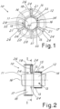
- Figure 1 shows an assembly, denoted generally by 10, for locking cores with a first diameter and a second diameter greater than the first diameter on a shaft 11 of a winding machine, designed in accordance with the invention.
- This assembly 10 is intended to be mounted on a winding shaft 11 of a known winding machine, which is not shown or described in detail since it is well-known per se and may be easily imagined by the person skilled in the art.
- assemblies 10 may be mounted next to each other on the shaft 11 (for example using systems known in the sector and therefore not shown or described in detail) so as to receive one or more cores mounted on them and to controllably lock them to the shaft 11 of the winding machine.
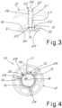
- a shaft assembly for a winding machine is thus provided, being formed by a plurality of devices according to the invention mounted on the rotation shaft, as partially and schematically shown in broken lines by way of example in Figures 2 and 5 .
- the assembly 10 comprises a cylindrical locking device 12 which may have a generally annular form and has a plurality of engaging elements 13 which are controllable so as to project by a greater or smaller amount from a radially outer surface 14 thereof in order to lock a core 15 with a first diameter fitted onto it.
- the radial movement of the engaging elements 13 may be performed with any one of the known systems used for conventional locking devices, as may be easily imagined by the person skilled in the art, also based on the description which follows.
- the engaging elements 13 may be all arranged in a same plane transverse to the axis 16 of rotation of the shaft 11 or may be arranged in two or more transverse planes which are spaced along the axis 16.
- the figures show by way of example engaging elements 13 in two different transverse planes.
- the engaging elements 13 are arranged distributed (for example equidistant) along the circumference of the device 12. In the case where the engaging elements 13 are arranged in several transverse planes, they may also be circumferentially staggered relative to each other in the different planes as can be seen in the figures showing by way of example two planes.
- the engaging elements 13 may be spheres or cylinders with their axis parallel to the axis of the body 12.
- Said locking device 12 may also be a locking device essentially according to the prior art and is suitable for coaxially receiving on itself a reel core 15 with a first diameter, as shown schematically in Figure 2 , in accordance with a prior art use of a device for locking cores on a shaft, and the engaging elements 13 are controllable as in the prior art so as to move radially outwards into a position which is intended to engage with first-diameter cores which are coaxially mounted on the devices 12 placed on the shaft 11.
- At least one annular element 17 for adapting the diameter which is suitable for being coaxially and removably fitted on the cylindrical device 12 and which is suitable for coaxially receiving on it a core 19 with a different diameter greater than the first diameter (as shown for example in Figure 2 ).
- the annular element has a plurality of auxiliary engaging elements 24 which are controllable so as to move or be locked radially in an operating condition intended to engage with said different-diameter cores which are coaxially fitted on it.
- the annular element 17 has its radially outer surface 18 which is suitable for receiving the core 19 and from which the auxiliary engaging elements 24 may engage by a greater or lesser amount.
- auxiliary engaging elements 24 are displaceable or lockable in their operating condition by means of an outward movement of engaging elements of the plurality of engaging elements 13 of the device 12 when the annular element 17 is coaxially arranged on the cylindrical device.
- the annular element 17 is intended to be removably and coaxially fitted, with its radially inner surface 20, over the radially outer surface 14 of the annular locking device 12.
- Each auxiliary engaging element 24 may be a rolling member, for example in the form of a sphere or cylinder with its axis parallel to the axis of the annular element (and therefore the shaft 11).
- the annular element 17 in order to obtain the said movement or locking of the auxiliary engaging elements 24, has internally radial seats 21 with a first end 22 which is open on its radially outer surface 18 and a second end 23 which is open on its radially inner surface 20.
- One of the auxiliary engaging elements 24 is present on the first end 22 of each seat 21.
- the opposite second end 23 faces an engaging element of the plurality of engaging elements 13 when the annular element 17 is coaxially arranged on the cylindrical device 12.
- the ends 22 of the seats have dimensions such as to prevent the auxiliary engaging elements 24 from coming out completely of the annular element 17 through the surface 18.
- the opening on the surface may be made slightly smaller than the diameter of the engaging element 24.
- the radial seat 21 may have for example the end 22 which carries a ring 25 limiting the movement of the respective auxiliary engaging element 24 outwards.
- the ring 25 may be fixed in place in the seat by means of screwing, gluing, an interlocking fit, etc.
- pins 26 are housed inside the seats 21, said pins being axially slidable in the radial direction with respect to the annular element and receive at an inner end the radially outwards movement of a corresponding engaging element of the plurality of engaging elements 13 so as to be able to displace or lock in the operating condition the corresponding auxiliary engaging element 24 depending on the corresponding movement of the engaging element 13.
- the sliding movement of the pin may be free towards the inside when the corresponding engaging element 13 is in its rest condition retracted, such that the auxiliary engaging element may be retracted into the radially outer surface of the annular element by a first amount.
- the sliding movement of the pin may be locked towards the inside when the corresponding engaging element 13 is in its more projecting operating condition, such that the auxiliary engaging element in this condition can retract into the radially outer surface of the annular element by a smaller amount or also be entirely locked in the direction towards the inside of the annular element.
- the auxiliary engaging element is in its operating condition for locking the core 19 (not shown) on the annular element.
- the engaging element 13, during its radial outward movement may preferably project so as to push directly onto the facing end of the pin, which in turn presses against the auxiliary engaging element 24.
- the pins may be pushed elastically outwards, namely towards the respective auxiliary engaging element 24 by means of an elastic element.
- the elastic element may be made preferably with a helical spring 27 fitted onto the pin.
- the pin may have a rear part which is narrower than its front part and the seat may have an inner end 23 which is correspondingly narrower so that a space with end stops may be formed in order to receive the spring.
- the ring 25 may also form an end-of-travel stop towards the outside for the pin and may also allow mounting of pin and spring inside the seat before being inserted in the end 22 of the seat.
- the auxiliary engaging elements 24 are elastically pushed outwards when they are in the non-operating condition. In this way, it may be ensured that that there is a prestressing force acting on the auxiliary engaging elements also when they are in the rest position, so as to provide a small resistance to the free axial rotation of a core 19 fitted onto the annular element 17, when this is necessary for activation of the underlying device 12 towards its locked operating position, using a known technique which may be easily imagined by the person skilled in the art.
- a removable-fastening system or element may be advantageously provided between the radially inner surface of the annular element 17 and the radially outer facing surface of the device 12.
- Said system may for example comprise a screw 28 screwed radially from the outside of the adapter towards the outer surface of the device 12.
- a removable-fastening element 29 which comprises a housing seat and a locating element inserted inside the seat.
- the locating element may be formed by a pin inserted axially inside the housing seat, parallel to the axis of the adapter.
- the seat may be formed partly in the outer surface of the device 12 and partly in the inner surface of the annular element 17, as shown in Figure 1 , so as to form a fastening system preventing relative axial rotation of the device 12 and the annular element 17 and also a precise reference point for their relative angular position about the common axis 16. This facilitates mounting, in the correct position, of the annular element 17 on the device 12.
- the locating element 29 may also be formed with a ball 35 (shown in broken lines in Figure 5 ), which is stably housed in the appropriate seat in the device 12 so as to project elastically from its outer surface (for example by means of an underlying spring 36) so as to be inserted inside a corresponding seat or channel formed in the inner surface of the adapter 17.
- This locating element with the ball 35 may also have the function of providing a prestressing force and keeping in position a core 15 when it is mounted on the device 12 without the adapter element 17.
- the ball and the spring may also form part of a cartridge radially inserted in the outer surface of the device 12.
- the device 12 may be advantageously made so as to comprise an inner ring 30 and an outer ring 30 which are concentric with each other, with the engaging elements 13 of the plurality which emerge through eyelets 32 on the peripheral surface of the outer ring 31.
- the outer ring is made so as to be rotatable with respect to the inner ring between a first angular rest position, in which the first engaging elements 13 may be retracted inside the outer ring by a first amount, and a second angular operating position, in which the engaging elements 13 may be retracted by an amount less than in the first angular rest position.
- inclined siding surfaces 33 may be provided on the inner ring.
- rolling balls may also be provided between their two facing surfaces.
- An element 34 housed between the rings may also be provided for limiting the angular rotation thereof.
- Figures 4 , 5 and 6 are similar to Figures 1, 2 and 3 , but with the rings which are displaced form the non-operating position of the engaging elements 13 into the operating position for locking the cores.
- the devices 12 are mounted on the shaft 11 of the machine and may thus form normal locking devices with the engaging elements 13 which lock the cores 15 on the shaft.
- the annular elements 17 suitable for that different greater diameter are mounted on the devices 12.
- the auxiliary engaging elements 24 essentially reproduce the movement of the engaging elements 13 and lock the cores 19 on the shaft.
- a first diameter may be 3 inches, while a different, greater diameter may be 6 inches, which are the core diameters which are most widely used.
- annular elements 17 with an outer diameter suitable for other core diameters, it is possible to mount and lock on the shaft these other diameters.
- locking devices 12 which are stably mounted on the shaft 11 and then provide and mount rapidly on these devices 12 the annular elements 17 suitable for the desired core diameter, choosing them from among a set of annular elements made according to the invention for the different core diameters which are to be used.
- the annular diameter adapters have a simple structure and operating mode, they may be more cost-efficient than the conventional locking devices. Moreover, the mounting and extraction thereof onto/from the bodies 12 may be fast and easy, with consequent shorter machine downtimes compared to the changing of conventional locking devices on the shaft 11.
- the annular adapter element may also be hollowed out so as to use less material and be lighter, as can be seen clearly in Figures 1 and 4 .
- the assembly formed by a rotational shaft and a plurality of devices according to the invention may also comprise further known mechanisms such as, for example, known pneumatic systems for locking the devices on the shaft, as may be easily imagined by the person skilled in the art.
- the engaging elements 13 and the surfaces 33 for their movement between the two - rest and operating - positions may also have a form different from that shown and for example may be made using other types known in the sector, and likewise the entire device 12 and the system for moving its engaging elements 13 may be made in another way.
- the annular element according to the invention designed with suitable dimensions, may be used as a diameter adapter element on any known locking device for cores in winding machines.
Landscapes
- Winding Of Webs (AREA)
- Replacement Of Web Rolls (AREA)
Applications Claiming Priority (1)
| Application Number | Priority Date | Filing Date | Title |
|---|---|---|---|
| IT102022000000188A IT202200000188A1 (it) | 2022-01-10 | 2022-01-10 | Adattatore di diametro per un dispositivo di blocco di anime per alberi di bobinatrici |
Publications (1)
| Publication Number | Publication Date |
|---|---|
| EP4209441A1 true EP4209441A1 (de) | 2023-07-12 |
Family
ID=80933248
Family Applications (1)
| Application Number | Title | Priority Date | Filing Date |
|---|---|---|---|
| EP23150651.0A Withdrawn EP4209441A1 (de) | 2022-01-10 | 2023-01-09 | Durchmesseradapter für eine vorrichtung zum verriegeln von hülsen für wickelmaschinenwellen |
Country Status (2)
| Country | Link |
|---|---|
| EP (1) | EP4209441A1 (de) |
| IT (1) | IT202200000188A1 (de) |
Citations (6)
| Publication number | Priority date | Publication date | Assignee | Title |
|---|---|---|---|---|
| US2904279A (en) * | 1957-02-06 | 1959-09-15 | Lynn H Ewing | Expanding chuck |
| US4651643A (en) * | 1985-02-14 | 1987-03-24 | Sidney Katz | Adaptors for use with printing cylinder mandrels |
| EP1997757B1 (de) * | 2007-05-26 | 2011-03-30 | Koenig & Bauer Aktiengesellschaft | Rollenwechsler mit einem Spannkonus zur Aufnahme von einer aufgewickelten Materialrolle tragenden Hülse |
| US20120286087A1 (en) * | 2011-05-11 | 2012-11-15 | Jose Antonio Alvarez Tapia | Spindle adapter |
| JP5768806B2 (ja) * | 2012-12-14 | 2015-08-26 | 株式会社片岡機械製作所 | フリクション巻軸 |
| JP2018135205A (ja) * | 2017-02-24 | 2018-08-30 | 株式会社東伸 | アダプタ |
-
2022
- 2022-01-10 IT IT102022000000188A patent/IT202200000188A1/it unknown
-
2023
- 2023-01-09 EP EP23150651.0A patent/EP4209441A1/de not_active Withdrawn
Patent Citations (6)
| Publication number | Priority date | Publication date | Assignee | Title |
|---|---|---|---|---|
| US2904279A (en) * | 1957-02-06 | 1959-09-15 | Lynn H Ewing | Expanding chuck |
| US4651643A (en) * | 1985-02-14 | 1987-03-24 | Sidney Katz | Adaptors for use with printing cylinder mandrels |
| EP1997757B1 (de) * | 2007-05-26 | 2011-03-30 | Koenig & Bauer Aktiengesellschaft | Rollenwechsler mit einem Spannkonus zur Aufnahme von einer aufgewickelten Materialrolle tragenden Hülse |
| US20120286087A1 (en) * | 2011-05-11 | 2012-11-15 | Jose Antonio Alvarez Tapia | Spindle adapter |
| JP5768806B2 (ja) * | 2012-12-14 | 2015-08-26 | 株式会社片岡機械製作所 | フリクション巻軸 |
| JP2018135205A (ja) * | 2017-02-24 | 2018-08-30 | 株式会社東伸 | アダプタ |
Also Published As
| Publication number | Publication date |
|---|---|
| IT202200000188A1 (it) | 2023-07-10 |
Similar Documents
| Publication | Publication Date | Title |
|---|---|---|
| EP0860007B1 (de) | Bandkopfbetätiger-zusammenbau mit stossdämpfungsmanschette | |
| US5193825A (en) | Apparatus for adjusting the center of a collet | |
| US4395051A (en) | Quick-change holder | |
| US20140353929A1 (en) | Expanding arbor | |
| EP0780220B1 (de) | Reifenaufbautrommel | |
| JP6889113B2 (ja) | コレットチャック | |
| WO2013037990A1 (en) | Expanding arbor | |
| US5177830A (en) | Rotatively driveable tool chucking device | |
| CN110944782B (zh) | 自锁空心转轴夹紧机构 | |
| EP4209441A1 (de) | Durchmesseradapter für eine vorrichtung zum verriegeln von hülsen für wickelmaschinenwellen | |
| US11033971B2 (en) | Clamping device for holding a collet | |
| US5314135A (en) | Expandable mandrel | |
| US5027682A (en) | Attachment mounting mechanism in a machine tool | |
| US4285528A (en) | Chuck assembly | |
| EP0020517A4 (de) | Spanndorn zum halten eines stapels von elementen. | |
| US2893744A (en) | Centering chuck | |
| US4175712A (en) | Chucking spindle for the reception of a bobbin carrier | |
| US3623741A (en) | Bidirectionally operable torque actuated expandable core chuck | |
| US4465244A (en) | Expanding core chuck | |
| EP4237364A1 (de) | Spannfutter mit verbesserter drehmomentübertragung und -zentrierung | |
| JPS5947107A (ja) | 加工片用膨張収縮型把持装置 | |
| EP3272690A1 (de) | Ringvorrichtung für wellen in wickelmaschinen und damit ausgerüstete welle | |
| US4676516A (en) | High speed chuck assembly | |
| US3045265A (en) | Tapping spindle with yieldable nut retaining means | |
| US5388018A (en) | Scanning device for a magnetic-tape apparatus having a radially expandable clamping hub |
Legal Events
| Date | Code | Title | Description |
|---|---|---|---|
| PUAI | Public reference made under article 153(3) epc to a published international application that has entered the european phase |
Free format text: ORIGINAL CODE: 0009012 |
|
| STAA | Information on the status of an ep patent application or granted ep patent |
Free format text: STATUS: THE APPLICATION HAS BEEN PUBLISHED |
|
| AK | Designated contracting states |
Kind code of ref document: A1 Designated state(s): AL AT BE BG CH CY CZ DE DK EE ES FI FR GB GR HR HU IE IS IT LI LT LU LV MC ME MK MT NL NO PL PT RO RS SE SI SK SM TR |
|
| STAA | Information on the status of an ep patent application or granted ep patent |
Free format text: STATUS: REQUEST FOR EXAMINATION WAS MADE |
|
| 17P | Request for examination filed |
Effective date: 20231228 |
|
| RBV | Designated contracting states (corrected) |
Designated state(s): AL AT BE BG CH CY CZ DE DK EE ES FI FR GB GR HR HU IE IS IT LI LT LU LV MC ME MK MT NL NO PL PT RO RS SE SI SK SM TR |
|
| RAP3 | Party data changed (applicant data changed or rights of an application transferred) |
Owner name: M.E.C. MECHANICAL ENGINEERING CONSULTING SRL |
|
| RAP3 | Party data changed (applicant data changed or rights of an application transferred) |
Owner name: M.E.C. MECHANICAL ENGINEERING CONSULTING SRL |
|
| STAA | Information on the status of an ep patent application or granted ep patent |
Free format text: STATUS: EXAMINATION IS IN PROGRESS |
|
| 17Q | First examination report despatched |
Effective date: 20250225 |
|
| STAA | Information on the status of an ep patent application or granted ep patent |
Free format text: STATUS: THE APPLICATION IS DEEMED TO BE WITHDRAWN |
|
| 18D | Application deemed to be withdrawn |
Effective date: 20250626 |