EP4209183A1 - Delivery and detachment system imposing a friction force on a securement wire to minimize movement of an implantable intravascular device - Google Patents
Delivery and detachment system imposing a friction force on a securement wire to minimize movement of an implantable intravascular device Download PDFInfo
- Publication number
- EP4209183A1 EP4209183A1 EP23150411.9A EP23150411A EP4209183A1 EP 4209183 A1 EP4209183 A1 EP 4209183A1 EP 23150411 A EP23150411 A EP 23150411A EP 4209183 A1 EP4209183 A1 EP 4209183A1
- Authority
- EP
- European Patent Office
- Prior art keywords
- support tube
- inner support
- passageway
- delivery
- wire
- Prior art date
- Legal status (The legal status is an assumption and is not a legal conclusion. Google has not performed a legal analysis and makes no representation as to the accuracy of the status listed.)
- Granted
Links
Images



Classifications
-
- A—HUMAN NECESSITIES
- A61—MEDICAL OR VETERINARY SCIENCE; HYGIENE
- A61B—DIAGNOSIS; SURGERY; IDENTIFICATION
- A61B17/00—Surgical instruments, devices or methods
- A61B17/12—Surgical instruments, devices or methods for ligaturing or otherwise compressing tubular parts of the body, e.g. blood vessels or umbilical cord
- A61B17/12022—Occluding by internal devices, e.g. balloons or releasable wires
-
- A—HUMAN NECESSITIES
- A61—MEDICAL OR VETERINARY SCIENCE; HYGIENE
- A61B—DIAGNOSIS; SURGERY; IDENTIFICATION
- A61B17/00—Surgical instruments, devices or methods
- A61B17/12—Surgical instruments, devices or methods for ligaturing or otherwise compressing tubular parts of the body, e.g. blood vessels or umbilical cord
- A61B17/12022—Occluding by internal devices, e.g. balloons or releasable wires
- A61B17/12099—Occluding by internal devices, e.g. balloons or releasable wires characterised by the location of the occluder
- A61B17/12109—Occluding by internal devices, e.g. balloons or releasable wires characterised by the location of the occluder in a blood vessel
- A61B17/12113—Occluding by internal devices, e.g. balloons or releasable wires characterised by the location of the occluder in a blood vessel within an aneurysm
-
- A—HUMAN NECESSITIES
- A61—MEDICAL OR VETERINARY SCIENCE; HYGIENE
- A61B—DIAGNOSIS; SURGERY; IDENTIFICATION
- A61B17/00—Surgical instruments, devices or methods
- A61B17/12—Surgical instruments, devices or methods for ligaturing or otherwise compressing tubular parts of the body, e.g. blood vessels or umbilical cord
- A61B17/12022—Occluding by internal devices, e.g. balloons or releasable wires
- A61B17/12131—Occluding by internal devices, e.g. balloons or releasable wires characterised by the type of occluding device
- A61B17/1214—Coils or wires
-
- B—PERFORMING OPERATIONS; TRANSPORTING
- B29—WORKING OF PLASTICS; WORKING OF SUBSTANCES IN A PLASTIC STATE IN GENERAL
- B29D—PRODUCING PARTICULAR ARTICLES FROM PLASTICS OR FROM SUBSTANCES IN A PLASTIC STATE
- B29D23/00—Producing tubular articles
-
- A—HUMAN NECESSITIES
- A61—MEDICAL OR VETERINARY SCIENCE; HYGIENE
- A61B—DIAGNOSIS; SURGERY; IDENTIFICATION
- A61B17/00—Surgical instruments, devices or methods
- A61B2017/00526—Methods of manufacturing
-
- A—HUMAN NECESSITIES
- A61—MEDICAL OR VETERINARY SCIENCE; HYGIENE
- A61B—DIAGNOSIS; SURGERY; IDENTIFICATION
- A61B17/00—Surgical instruments, devices or methods
- A61B2017/00831—Material properties
- A61B2017/0084—Material properties low friction
-
- A—HUMAN NECESSITIES
- A61—MEDICAL OR VETERINARY SCIENCE; HYGIENE
- A61B—DIAGNOSIS; SURGERY; IDENTIFICATION
- A61B17/00—Surgical instruments, devices or methods
- A61B2017/00831—Material properties
- A61B2017/00858—Material properties high friction or non-slip
-
- A—HUMAN NECESSITIES
- A61—MEDICAL OR VETERINARY SCIENCE; HYGIENE
- A61B—DIAGNOSIS; SURGERY; IDENTIFICATION
- A61B17/00—Surgical instruments, devices or methods
- A61B17/12—Surgical instruments, devices or methods for ligaturing or otherwise compressing tubular parts of the body, e.g. blood vessels or umbilical cord
- A61B17/12022—Occluding by internal devices, e.g. balloons or releasable wires
- A61B2017/1205—Introduction devices
- A61B2017/12054—Details concerning the detachment of the occluding device from the introduction device
Definitions
- the present invention relates to a system for delivery and detachment of an implantable intravascular device used during an endovascular treatment or procedure.
- the present invention is directed to a delivery and deployment system including an inner support tube having a passageway in an axial direction with a securement wire threaded therethrough.
- a delivery and deployment system including an inner support tube having a passageway in an axial direction with a securement wire threaded therethrough.
- Implantable intravascular devices are commonly used in endovascular procedures or treatments of various vascular ailments, for example, brain aneurysms.
- a catheter is inserted into the femoral artery in patient's leg and guided by imaging navigated through the vessel to the target site in the brain where the aneurysm is located. With the distal end of the catheter properly positioned on a proximal side of the aneurysm, a microcatheter is tracked through the catheter to the proximal side of the aneurysm.
- a delivery and deployment system loaded with an implantable intravascular device e.g., embolic coil
- an implantable intravascular device e.g., embolic coil
- the implantable intravascular device is mechanically secured within the delivery system, typically via a wire (e.g., securement wire or pull wire).
- a wire e.g., securement wire or pull wire.
- the wire is severed releasing the implantable intravascular device (e.g., embolic coil) to be deposited within the aneurysm.
- embolic coil e.g., embolic coil
- Severing of the embolic coil from the securement wire is typically achieved by passing of a small electrical current through the wire. This process is repeated until the area of the vessel with the weakened wall is tightly packed with numerous embolic coils occluding blow flow thereto thereby preventing rupture.
- the present invention is directed to an improved system for delivery and detachment of an implantable intravascular device that intentionally introduces a controlled amount of friction force on the securement wire to minimize or prevent unwanted shifting, movement, or translation during delivery of the implantable intravascular device to the target site in the artery.
- Another aspect of the present invention relates to a delivery and detachment system for an implantable intravascular device, in which the system includes an inner support tube having a passageway extending in an axial direction from a proximal end to an opposite distal end.
- the system further includes a securement wire extending through the passageway of the inner support tube. Imposed on the securement wire is a controlled friction force established within an intentional friction zone located anywhere between the distal end of the inner support tube and a midway point between the respective proximal and distal ends of the inner support tube.
- Yet another aspect of the invention is directed to a method for manufacture of a delivery and detachment system for an implantable intravascular device, as described in the preceding paragraph.
- an inner support tube having a passageway extending in an axial direction from a proximal end to an opposite distal end is provided.
- a securement wire is threaded through the passageway of the inner support tube, imposing on the securement wire a controlled friction force established within an intentional friction zone located anywhere between the distal end of the inner support tube and a midway point between the respective proximal and distal ends of the inner support tube.
- While still another aspect of the present invention relates to a method of using a delivery and detachment system for an implantable intravascular treatment device.
- the delivery and detachment system including an inner support tube having a passageway extending in an axial direction between a proximal end and an opposite distal end; and the delivery; and detachment system further including a securement wire extending through the passageway of the inner support tube; imposed on the securement wire is a controlled friction force established within an intentional friction zone located anywhere between the distal end of the inner support tube and a midway point between the respective proximal and distal ends of the inner support tube.
- the method of using the system being that during delivery of the implantable intravascular treatment device to a target site, the imposed controlled friction force minimizes movement of the securement wire relative to the inner support tube. Whereas, upon the implantable intravascular treatment device reaching the target site, a force is applied in a proximal direction on the securement wire sufficient to exceed the imparted controlled friction force and releasing the implantable intravascular device from the delivery and detachment system.
- distal or proximal are used in the following description with respect to a position or direction relative to the treating physician or medical interventionalist.
- distal or disally are a position distant from or in a direction away from the physician or interventionalist.
- Proximal or “proximally” or “proximate” are a position near or in a direction toward the physician or medical interventionist.
- occlusion or “clot” or “blockage” are used interchangeably.
- an endovascular treatment procedure e.g., coil embolization
- the system to reliably deliver and detach/deploy/deposit/release the implantable intravascular device (e.g., embolic coil) at a precise location or target site (e.g., aneurysm) within a vessel or artery.
- the implantable intravascular device e.g., embolic coil
- the implantable intravascular device is releasably loaded on (e.g., secured to) the distal end of a delivery and detachment system that together as a unit are advanced to the desired target site in the vessel or artery.
- Releasable securement of the implantable intravascular device is via a securement wire (e.g., pull-wire) extending axially in a proximal direction through the delivery and detachment system.
- a securement wire e.g., pull-wire
- the interventionalist applies sufficient force in a proximal direction on the securement wire to release (e.g., disengage) the implantable intravascular device for deposit at that location within the artery. Any shifting, translation, or movement of the securement wire during delivery of the implantable intravascular device may result in imprecise positioning and depositing offset from the intended target site in the artery or vessel.
- the present inventive delivery system minimizes or prevents unwanted translation, shifting, or movement of the securement wire during delivery of the implantable intravascular device to the target site in the artery by intentionally introducing or imposing a controlled friction force on the securement wire within an intentional friction zone.
- Figure 1 is a longitudinal/axial cross-sectional view of an exemplary assembled delivery and detachment system 100 in accordance with the present invention with an implantable intravascular device (e.g., embolic coil) 130 loaded thereto.
- Delivery and detachment system 100 has a proximal end 105 and an opposite distal end 110 to which the implantable intravascular device (e.g., embolic coil) 130 is releasably secured thereto.
- System 100 includes a main or outer delivery tube 115 having a channel 113 extending in a longitudinal/axial direction therethrough.
- Insertable into the distal end of the channel 113 of the main delivery tube 115 is a proximal end of an inner support tube 140 which itself has a passageway 143 defined therethrough in a longitudinal/axial direction.
- a coil 120 (e.g., a helical coil) is disposed radially outward of the outer surface of the inner support tube 140.
- the outer sleeve is a thermoplastic elastomer (TPE) such as a polyether block amide (PEBA) known under the tradename of PEBAX ® .
- TPE thermoplastic elastomer
- PEBA polyether block amide
- a compressible component e.g., a helical detachment coil
- the outer sleeve 135 stops proximally of (does not extend in an axial direction over or cover any portion of the compressible component 125).
- the inner support tube 140 terminates proximally (i.e., does not extend into the cavity) of the compressible component 125.
- An implantable intravascular device (e.g., embolic coil) 130 is releasably connected to the distal end 110 of the delivery and detachment system 100 via a loop wire 155 threaded through an engagement device (e.g., proximal key) 160 disposed between the distal end of the compressible component 125 and the proximal end of the implantable intravascular device 130.
- an engagement device e.g., proximal key
- Respective free proximal ends of the loop wire 155 are permanently affixed to an inner surface of the compressible component 125, whereas an opposite distal end of loop wire 155 forms a closed loop.
- Engagement component (e.g., proximal key) 160 has an opening.
- the implantable intravascular device 130 is releasably attached, connected, or secured to the distal end 110 of the delivery and detachment system 100 by bending a portion of the closed loop distal end of the loop wire 155 upwards (e.g., perpendicularly to the axial direction of the delivery and detachment system) through the opening of the engagement component 160 and threading the distal end of the securement wire (e.g., pull wire) 150 in a distal direction through the bent upwards closed loop distal end of the loop wire 155.
- the securement wire e.g., pull wire
- Securement wire 150 is depicted as straight (i.e., extending or moving uniformly in one direction only; without a curve, kink, or bend); however, a non-straight, curved, kinked, or bent securement wire is possible to impart an even greater friction force.
- Engagement of the distal end of the securement wire 150 within the closed loop distal end of the loop wire 155 secures the engagement component (e.g., proximal key) 160 and implantable intravascular device (e.g., embolic coil) 130 attached distally thereto to the distal end of the delivery and detachment system 100.
- the implantable intravascular device 130 is deployed, released, or deposited at a target site in the artery by subjecting the securement wire 150 to an axial force in a proximal direction (e.g., pulling in a proximal direction). Sufficient axial force is applied in the proximal direction so that the distal end of the securement wire 150 is disengaged (i.e., free from, clear of, or no longer constrained by) the loop wire 155. Now released from the loop wire 155, the securement wire 150 is no longer connected to the engagement component (e.g., proximal key) 160 or implantable intravascular device 130 attached thereto.
- the engagement component e.g., proximal key
- Compressible component 125 may initially be under compression subject to decompression/expansion once the securement wire 150 is disengaged from the loop wire 155 imparting a force in a distal direction on the proximal end of the implantable intravascular device (e.g., embolic coil) 130.
- the loop wire 155 preferably has sufficient flexibility such that when the decompression/expansion force is imparted by the compressible component 125 the loop wire 155 moves out of the opening of the engagement component (e.g., proximal key) 160 thereby detaching/releasing the implantable intravascular device 130 from the delivery system 100.
- the force imparted by the compressible component 125 during decompression/expansion preferably pushes the implantable intravascular device 130 in a distal direction away from the distal end 110 of the delivery system 100 creating a predetermined separation distance therebetween upon deployment.
- Other purely mechanical (non-thermal and non-electrical) arrangements releasable upon application of an axial force in a proximal direction e.g., pulling force
- a stretch resistant element 163 is preferably disposed internally within the cavity of the implantable intravascular device 130. At a distal end, stretch resistant element 163 is secured via a bead or other stopping component 164 having an outer diameter that prevents passage in a proximal direction into the interior cavity of the implantable intravascular device 130, while its opposite proximal end is secured to the distal end of the engagement component 160 (e.g., threaded through an opening thereof).
- marker bands detectable through imaging may be provided along regions of one or more components of the delivery and detachment system.
- marker bands 195a, 195b e.g., a fluor-saver marker
- marker bands 195a, 195b may be disposed along an outer surface of a proximal section of the main delivery tube 115 and a distal section of the coil body 120 (preferably aligned with that of the side port openings 165a, 165b, 165c created in the inner support tube 140).
- the arrangement, number, and use altogether of marker bands is optional.
- a plurality of radially inward cuts are made extending from the outer surface through to (intersecting) the passageway 143 creating a plurality of side port openings 165 that allow a fluid (e.g., the reflowable material of the outer sleeve) to flow/seep therethrough.
- a fluid e.g., the reflowable material of the outer sleeve
- distal section is expressly defined as any section, region, portion, or area along the inner support tube that satisfies the following conditions: (i) in a distal direction relative to a midpoint between opposing proximal and distal ends/tips of the inner support tube; and (ii) in a proximal direction relative to the distal end/tip of the inner support tube.
- the selected distal section along which the intentional friction zone is created is located anywhere in a region between, without including either, the distal end/tip and the midpoint of the inner support tube.
- Figure 3A is a perspective view of an exemplary supporting and cutting structure 300 used to make radially inward skived cuts into an outer surface of the inner support tube 140 through to (intersecting) the passageway 143 defined axially therein.
- the inner support tube 140 in which the side openings are to be created is supported on the structure 300 and held in position by a clamp 320 ( Figures 3A & 3D ).
- a side port template 309 having a plurality of troughs (305a, 305b, 305c) arranged parallel to one another in an X-direction define the location, spacing, arrangement and the angle of the cuts to be made to the inner support tube 140 to create the side port openings 165 having a desired geometric cross-sectional shape (e.g., trapezoidal shape).
- Three troughs (305a, 305b, 305c) are shown in the example represented in Figures 3A & 3D all having the same cross-sectional shape (e.g., trapezoidal shape); however, the number, location, spacing, arrangement, and/or cross-sectional shape of each trough may be designed, as desired.
- adjacent side port openings defined in the inner support tube 140 depicted in Figure 2A are separated from one another both in a longitudinal/axial direction and in a radial direction. That is, side port 165a is separated both in a longitudinal/axial direction and a radial direction (approximately 180°) relative to that of adjacent side port 165b, as is true for all adjacent side port openings illustrated.
- Three side port openings 165a-165c are illustrated in Figure 2A ; however, any number of two or more side port openings may be made, as desired.
- each side port opening may be modified, as desired, so long as each side port opening extends radially inward through the inner support tube 140 (i.e., from its outer surface to its passageway 143).
- a controlled amount of intentionally introduced friction force imposed on the securement wire 150 when threaded through the passageway 143 is produced by selecting: (i) the number of side port openings; (ii) the location and arrangement of the side port openings (both longitudinally/axially and radially); and (iii) the dimensions in an axial direction (Z-direction) and in a radial direction (X-direction) of each side port opening created in the inner support tube.
- each side port opening of the inner support tube has an axial length of approximately 1mm, with at least approximately 1mm separation in an axial direction between adjacent side port openings.
- the spacing of cuts in a radial direction may be more compact depending on such factors as the depth (radially inward) of the cut and amount of remaining material (i.e., strength) of the inner support tube. Referring to Figures 6A-6D varying exemplary depth cuts are made to the inner support tube.
- Figures 6A & 6B depict a longitudinal cut-away view and a bottom portion end view, respectively, of the inner support tube 140 having a side port opening 165 with a 25% depth (radially inward) cut
- Figures 6C & 6D depict the same views for a side port opening with a 50% depth (radially inward) cut.
- the deeper radial cut (50% depth) extending further radially inward into the clearance or free space within the passageway 143 of the inner support tube 140 when a smaller diameter protective metal wire/mandrel 311 is used.
- FIGS 3A & 3D depict an exemplary supporting and cutting device 300 including a substrate 301 and a corrugated/wave platform 308 having a plurality of longitudinally arranged parallel ridges and valleys 303 extending along the Z-axis.
- the inner support tube 140 in which the side port openings are to be created is placed within an associated one of the valleys (between adjacent ridges) 303 of the corrugated/wave platform 308 so that the longitudinal axis of the inner support tube 140 is arranged parallel with the Z-axis.
- Supporting and cutting device 300 further includes a side port template 309 having defined therein parallel to the Z-axis a series of channels 307 equal in number to that of the valleys 303 of the corrugated/wave platform 308. Each channel 307 of the side port template 309 is aligned in a Z-direction with a corresponding valley 303 of the corrugated/wave platform 308.
- Side port template 309 has a plurality of troughs (e.g., recesses) 305a-305c defined therein parallel to one another and extending along an X-axis perpendicular to the Z-axis.
- the number of troughs 305a-305c corresponds to the desired number of side port openings to be created in the inner support tube.
- Each trough 305a, 305b, 305c preferably, but need not necessarily, has the same cross-section parallel to the Z-axis.
- the channels 307 defined in the side port template 309 parallel with the Z-axis emerge on one side, extend across, and thereafter continue on the opposite side of each of the plurality of troughs 305a-305c.
- Each trough preferably has a trapezoidal like cross-sectional shape parallel to the Z-axis (i.e., tapered sides widening in opposing directions from a flat bottom surface) connecting the narrowing free ends of the tapered sides), as shown in Figures 3B & 3C .
- the preferred range of angularity of the tapered sides of the notch is an acute angle ⁇ (e.g., less than 90°) relative to the Z-axis extending perpendicularly through the channel 307.
- the inner support tube 140 in which the side port openings are to be created is placed/supported within one of the valleys 303 of the corrugated/wave shape platform 308 and slid along the Z-direction into an associated channel 307 defined through the side port template 309 ( Figure 3D ).
- the distal end of the inner support tube 140 emerges/exits from the channel 307, advances across the associated trough, and once again is received in the channel that picks up on the opposite side of the trough.
- the distal end of the inner support tube is preferably threaded/received once again in the channel at the opposite side of the final/last trough to ensure that the distal most end of the inner support tube is supported/held within the channel while the side port openings are being cut.
- FIG. 3E is an enlarged view of the inner support tube 140 extending across the trapezoidal trough 305a of the side port template 309 depicting the protective wire 311 as it is being advanced in a distal direction through the passageway 143 thereof.
- a blade 310 (e.g., razor blade) is receivable within an opening in a hinged mounting arm 312 the angle of which may be adjusted, as desired, via a rotating handle 315.
- the blade 310 is secured in place using a conventional locking mechanism (e.g., tightening thumb screw) at an acute angle ⁇ (less than 90° relative to the Z-axis), substantially conforming to the angle of the tapered sides of the trapezoidal trough.
- Each side port opening 165 is preferably made by two passes/cuts of the blade using the exemplary supporting and cutting device of Figure 3A , insufficient reflow of the material reaching the passageway of the inner support tube to create the intended friction zone being achieved if only a single cut (slit) was made.
- a first pass/cut within one of the troughs is made with the blade 310 oriented at an acute angle ⁇ (less than 90° relative to the Z-axis), as shown in Figure 3B , for each location of the side port opening. Thereafter, the rotating handle 315 is adjusted 180° (flipped horizontally) (as shown in Figure 3C ) at which position the second pass/cut is made with the blade to complete that particular side port opening. With the second pass/cut of the blade a piece (wedge) of the inner support tube bounded on either side by the respective passes/cuts is lifted or removed revealing the side port formed therein (and the now visible passageway). This process is repeated for each of the plurality of side ports desired in the distal section of the inner support tube.
- troughs 305a, 305c may be used to create side port openings 165a, 165c, respectively, while side port opening 165b may be created using trough 305b (after rotating the inner support tube 140 by 180°).
- Trapezoidal shape side cuts are preferred over a perpendicular cut relative to the X-axis to ensure that the size of the side port opening is sufficient to allow sufficient material to reflow/seep therethrough and into the passageway.
- a blade e.g., a razor blade, knife, or other cutting device 310 a plurality of radially inward cuts, preferably skived cuts, are made along the distal section or region of the inner support tube 140 to create the side port openings 165a-165c.
- Each radially inward skived cut removes a portion of the outer surface of the inner support tube 140 through to the longitudinal/axial passageway 143 extending from its proximal end/tip to its opposite distal end/tip.
- each side port opening may be modified, as desired.
- Each side port opening may have a uniform shape and size or vary, as desired.
- Inner support tube 140 prevents or minimizes stretch resistance of the securement wire 150 within the delivery system 100.
- the shape and size of the side port opening is selected with several competing considerations in mind.
- the side port opening is sufficient in size to allow reflow/seepage of the reflowable outer sleeve material and creation of a controlled amount of friction force on the securement wire. While, on the other hand, the wider the side port opening the weaker the ability of the inner support tube to provide such resistance.
- the present inventive inner support tube has been shown and described as having a plurality of side port openings defined therein with each side port opening being formed from two skived cuts.
- the angle of the single cut may be at any desired angle ⁇ in a range of 90° (relative to the Y-axis) ⁇ ⁇ >0° ( Figure 3C ).
- the inner support tube 140 comprising part of the present inventive delivery and detachment system is ready to be assembled. Specifically, the inner support tube 140 with the side port openings 165a, 165b, 165c defined in a distal section or region thereof is inserted into the interior cylindrical shape cavity formed by the coil 120. No portion of the inner support tube 140 extends in a longitudinal direction into the inner cavity of the compressible element 125, i.e., each of the side port openings 165 are disposed proximally of and separated a predetermined distance relative to the compressible element 125.
- the outer sleeve or covering 135 is positioned about or covering the outer surface of the coil 120.
- the inner support sleeve 140 is first inserted into the coil 120 which together as a unit are received within the outer sleeve 135. It is, however, also within the intended scope of the present invention to insert the coil 120 within the outer sleeve 135 to form a unit together and thereafter insert the inner support tube 140 into the inner cavity formed by the coil 120 that forms a unit with the outer sleeve 135.
- the order of assembly of these three components may be selected, as desired, and is within the intended scope of the prevent invention.
- a straight mandrel is inserted in a longitudinal direction through the passageway of the inner support tube 140 after being assembled together with the coil 120 and outer sleeve 135.
- the straight mandrel is heated to a prescribed fusing temperature to cause the outer sleeve 135 material (e.g., polyether block amide (PEBA) or other thermoplastic polymer) to reflow over the outer surface of the inner support tube 140 (made of a thermoplastic polymer material that does not melt at that temperature such as polyether ether ketone (PEEK)), radially inward through the side port openings 165a-165c, and partially into (along the inner wall of) the passageway 143.
- PEBA polyether block amide
- PEEK polyether ether ketone
- the inner diameter of the passageway of the inner support tube is reduced.
- the dimensions of the side port openings 165a-165c are selected to allow sufficient reflow of the material of the outer sleeve 135 to seep into the passageway 143 of the inner support tube 140 and create a controlled amount of friction force when directly physically contacting or directly engaging with the securement wire 150 threaded therethrough.
- the preferred range of outer diameter of the mandrel is in a range of approximately 70% - approximately 80% of the inner diameter of the passageway of the inner support tube.
- the outer diameter of the mandrel is 0.003 in. creating an intentional friction zone within a range of approximately 10 gF to approximately 20 gF to maintain the position of the securement wire in the delivery and detachment system during use.
- an additional contribution to the friction force imposed on the securement wire 150 may be produced by the frictional characteristics of the reflow material itself of the outer sleeve upon contacting with the outer surface of the mandrel.
- the mandrel used to reflow the outer sleeve material through the side port openings created in the inner support tube may be either coated (i.e., a mandrel coated with a lubricious coating) or non-coated (i.e., a mandrel not coated with a lubricious coating).
- a non-coated (free of any lubricious coating) mandrel the reflowed outer sleeve material adheres along the entire outer surface of the mandrel providing a predetermined amount of tacking force desirably contributing to the controlled friction force imposed on the outer surface of the securement wire.
- a mandrel coated with a lubricious material e.g., Polytetrafluoroethylene (PTFE)
- PTFE Polytetrafluoroethylene
- portions, sections, or regions of the outer surface of the mandrel exposed or lacking the coating will nevertheless exist producing patches in which a tacking force is produced.
- the tacking force is generated only in those random areas where the coating happens to be omitted, missing, or not present on the outer surface of the mandrel, whereas the tacking force produced when employing a non-coated mandrel extends substantially over the entire outer surface of the mandrel.
- withdraw of the mandrel from the three-component assembly allows cooling and hardening of the material of the outer sleeve 135 that has seeped through the side port openings into the passageway 143 of the inner support tube 140.
- the securement wire 143 secured at its distal end to a distal assembly comprising the detachment coil 125, proximal key 160 and implantable intravascular device 130 is threaded in a proximal direction through the passageway 143 of the three-component assembly (reflowed outer sleeve 130, coil 120, and inner support tube 140).
- a main delivery tube 115 having a channel 113 defined in a longitudinal/axial direction therethrough is assembled to the proximal end of the thus assembled delivery and detachment system.
- the proximal end of the inner support tube 140 extends in a proximal direction beyond the proximal end of the of the coil 120 and is sized to be telescopically receivable in the channel 113 of the main delivery tube 115.
- the threading of the securement wire 150 continues in a proximal direction through the channel 113 of the main delivery tube 115 and a lumen 170 of a proximal inner tube 145 whose distal end is received within the channel 113.
- a portion of the proximal end of the proximal inner tube 145 extends in a proximal direction relative to the proximal end of the main delivery tube 115.
- the proximal end of the securement wire that has been threaded in a proximal direction rough the lumen 170 of the proximal inner tube 145 and the channel 113 of the main delivery tube 115 is non-releasably secured (e.g., welded) 175 to the proximal end of the proximal inner tube 145.
- a catheter or microcatheter is navigated through the artery to the proximal side of the target site (e.g., aneurysm). Thereafter, using the assembled delivery and detachment system (as shown in Figure 1 ) the implantable intravascular device 130 releasably secured to the distal end thereof is advanced through the catheter or microcatheter to the target site.
- the target site e.g., aneurysm
- the amount of friction force imposed is sufficient to prevent or minimize shifting, movement or translation of the securement wire in the passageway during delivery able to be overcome only by application of sufficient axial force in a proximal direction on the securement wire when deploying (releasing) the implantable intravascular device from the delivery and detachment system to be precisely and accurately deposited at the target site in the artery.
- the design described above and illustrated narrows the inner diameter of the passageway defined in the inner support tube by reflow of the outer sleeve material through side port openings defined therein and into the passageway to intentionally narrow the inner diameter along those areas imposing a controlled friction force on the outer surface of the securement wire threaded therethrough.
- Other mechanical configurations to intentionally introduce a controlled friction force on the outer surface of the securement wire are contemplated and within the intended scope of the present invention.
- the design of the securement wire along a distal section thereof may be modified.
- a bend or kink in the otherwise substantially linear may be made along a distal section of the securement wire to intentionally create one or more points/sections/areas/regions of direct physical contact between the securement wire 150 and the inner wall of the passageway 143 of the inner support tube 140.
- the securement wire 140' in Figure 5 intentionally includes multiple bends or kinks configured as a trapezoidal shape establishing direct physical regions of contact of the securement wire with the inner wall of the passageway (approximately 180° radially from one another) resulting in the imposition of an intentional controlled friction force.
- Alternative configurations in the bending or kinking of the securement wire forming a variety of geometric shapes are contemplated and within the intended scope of the present invention.
- the number of, overall surface area, and/or spacing between points/sections/areas/regions of forced or intentional direct physical contact between the securement wire and the inner wall of the lumen of the inner support tube may be selected, as desired, to achieve a controlled intentional friction force on the securement wire when assembled within the delivery and detachment system.
- the intentional controlled friction force imposed by the bent or kinked securement wire directly engaging with the inner wall of the passageway of the inner support tube is sufficient to prevent or minimize shifting, translation or movement of the securement wire during delivery of the implantable intravascular device.
- the intentional controlled friction force is overcome releasing the implantable intravascular device 130 from the delivery and detachment system.
- the controlled amount of friction force imposed on the securement wire when assembled in the delivery and detachment system may be modified, as desired, to prevent or minimize shifting, translation, or movement of the securement wire during delivery and detachment of the implantable intravascular device, yet able to be overcome when sufficient force is applied in a proximal direction on the securement wire to release the implantable intravascular device.
- the present invention has been shown and described with respect to a delivery and detachment system loaded with an embolic coil during a coil embolization procedure in the treatment of an intracranial aneurysm. It is contemplated and within the intended scope of the present invention to utilize the present inventive delivery and detachment system for other types of implantable intravascular devices used in other endovascular treatment procedures.
Landscapes
- Health & Medical Sciences (AREA)
- Surgery (AREA)
- Life Sciences & Earth Sciences (AREA)
- Engineering & Computer Science (AREA)
- Heart & Thoracic Surgery (AREA)
- General Health & Medical Sciences (AREA)
- Nuclear Medicine, Radiotherapy & Molecular Imaging (AREA)
- Reproductive Health (AREA)
- Veterinary Medicine (AREA)
- Biomedical Technology (AREA)
- Public Health (AREA)
- Medical Informatics (AREA)
- Molecular Biology (AREA)
- Animal Behavior & Ethology (AREA)
- Vascular Medicine (AREA)
- Neurosurgery (AREA)
- Mechanical Engineering (AREA)
- Surgical Instruments (AREA)
- Prostheses (AREA)
- Media Introduction/Drainage Providing Device (AREA)
Abstract
Description
- The present invention relates to a system for delivery and detachment of an implantable intravascular device used during an endovascular treatment or procedure. In particular, the present invention is directed to a delivery and deployment system including an inner support tube having a passageway in an axial direction with a securement wire threaded therethrough. During delivery of the implantable intravascular device to a target site in the body, movement of the securement wire within the passageway of the inner support tube of the delivery and detachment system is minimized or prevented via an intentional friction zone.
- Implantable intravascular devices are commonly used in endovascular procedures or treatments of various vascular ailments, for example, brain aneurysms. A catheter is inserted into the femoral artery in patient's leg and guided by imaging navigated through the vessel to the target site in the brain where the aneurysm is located. With the distal end of the catheter properly positioned on a proximal side of the aneurysm, a microcatheter is tracked through the catheter to the proximal side of the aneurysm. A delivery and deployment system loaded with an implantable intravascular device (e.g., embolic coil) is introduced via the microcatheter to the target site. During delivery to the target site, the implantable intravascular device is mechanically secured within the delivery system, typically via a wire (e.g., securement wire or pull wire). When properly positioned at the target site (e.g., at the location of the aneurysm) the wire is severed releasing the implantable intravascular device (e.g., embolic coil) to be deposited within the aneurysm. Severing of the embolic coil from the securement wire is typically achieved by passing of a small electrical current through the wire. This process is repeated until the area of the vessel with the weakened wall is tightly packed with numerous embolic coils occluding blow flow thereto thereby preventing rupture.
- During delivery of an implantable intravascular device to a target site within the artery or vessel, conventional delivery and detachment systems are designed such that no friction force is intentionally imposed on the securement wire extending therethrough. It is the goal and intent of such conventional devices to avoid altogether imposing any friction force on the securement wire. An issue or drawback associated with such conventional friction-free configuration is that during delivery the securement wire is subject to unwanted shifting, movement, or translation resulting in potential imprecise delivery or detachment of the implantable intravascular device at the target site in the artery.
- It is therefore desirable to develop an improved system for delivery and detachment of an implantable intravascular device that intentionally introduces a controlled amount of friction force on the securement wire to minimize or prevent unwanted shifting, movement, or translation during delivery of the implantable intravascular device to the target site in the artery.
- The present invention is directed to an improved system for delivery and detachment of an implantable intravascular device that intentionally introduces a controlled amount of friction force on the securement wire to minimize or prevent unwanted shifting, movement, or translation during delivery of the implantable intravascular device to the target site in the artery.
- Another aspect of the present invention relates to a delivery and detachment system for an implantable intravascular device, in which the system includes an inner support tube having a passageway extending in an axial direction from a proximal end to an opposite distal end. The system further includes a securement wire extending through the passageway of the inner support tube. Imposed on the securement wire is a controlled friction force established within an intentional friction zone located anywhere between the distal end of the inner support tube and a midway point between the respective proximal and distal ends of the inner support tube.
- Yet another aspect of the invention is directed to a method for manufacture of a delivery and detachment system for an implantable intravascular device, as described in the preceding paragraph. Initially, an inner support tube having a passageway extending in an axial direction from a proximal end to an opposite distal end is provided. Then, a securement wire is threaded through the passageway of the inner support tube, imposing on the securement wire a controlled friction force established within an intentional friction zone located anywhere between the distal end of the inner support tube and a midway point between the respective proximal and distal ends of the inner support tube.
- While still another aspect of the present invention relates to a method of using a delivery and detachment system for an implantable intravascular treatment device. The delivery and detachment system including an inner support tube having a passageway extending in an axial direction between a proximal end and an opposite distal end; and the delivery; and detachment system further including a securement wire extending through the passageway of the inner support tube; imposed on the securement wire is a controlled friction force established within an intentional friction zone located anywhere between the distal end of the inner support tube and a midway point between the respective proximal and distal ends of the inner support tube. The method of using the system being that during delivery of the implantable intravascular treatment device to a target site, the imposed controlled friction force minimizes movement of the securement wire relative to the inner support tube. Whereas, upon the implantable intravascular treatment device reaching the target site, a force is applied in a proximal direction on the securement wire sufficient to exceed the imparted controlled friction force and releasing the implantable intravascular device from the delivery and detachment system.
- The foregoing and other features of the present invention will be more readily apparent from the following detailed description and drawings illustrative of the invention wherein like reference numbers refer to similar elements throughout the several views and in which:
-
Figure 1 is a longitudinal/axial cross-sectional view of an exemplary assembled system for delivery and detachment of an implantable intravascular device (e.g., embolic coil) in accordance with the present invention including an inner support tube having an intentional friction zone created along a distal section of an internal wall of a longitudinal/axial passageway defined therethrough with which a straight securement wire directly physically contacts or directly physically engages at multiple points; -
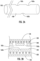
Figure 2A is a side view of an exemplary configuration of an altered inner support tube in accordance with the present invention having a plurality of side port openings created therein along a distal section thereof; -
Figure 2B is a partial longitudinal/axial cross-sectional view of the present inventive inner support tube prior to fusing of the reflowable material of the outer sleeve through the side port openings defined therein and into the longitudinal/axial passageway; -
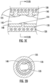
Figure 2C is a partial longitudinal/axial cross-sectional view of the present inventive inner support tube following seepage of the reflowable material of the outer sleeve through the side port openings and into the longitudinal/axial passageway thereby at those locations reducing the inner diameter and creating a friction zone along a distal section thereof; -
Figure 2D is a radial cross-sectional view along lines II(D)-II(D) ofFigure 2C showing the reflowable material of the outer sleeve seeped partially into the passageway of the inner support tube; -
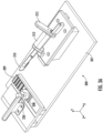
Figure 3A is a perspective view of an exemplary supporting and cutting structure for creating the radially inward side port openings in the inner support tube ofFigure 2A ; -
Figure 3B is an enlarged view parallel to the Z-axis of the blade ofFigure 3A making a first skived cut of one side port opening in the inner support tube; -
Figure 3C is an enlarged view parallel to the Z-axis of the blade (flipped 180° relative to the first skived cut ofFigure 3B ) making a second skived cut to complete the formation of the one side port opening in the inner support tube; -
Figure 3D is an enlarged view of the inner support tube supported by a corrugated/wave shape platform and side port template of the supporting and cutting structure ofFigure 3A while being secured in position via a clamp; -
Figure 3E is an enlarged view of two inner support tubes slid through/across associated troughs of the side port template of the supporting and cutting structure ofFigure 3A , wherein the lower inner support tube has a protective wire partially inserted through the longitudinal/axial passageway thereof; -
Figure 3F is an enlarged view of the protective wire being withdrawn from the passageway of the inner support tube after the creation of the side port openings therein; -
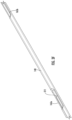
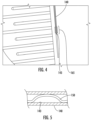
Figure 4 depicts the inner support tube with a single radially inward side port opening defined therein exposing the passageway thereof; -
Figure 5 is a partial longitudinal cut-away view of the inner support tube in an alternative embodiment in which the securement wire has multiple bends or kinks (e.g., trapezoidal in shape), each bend or kink in direct physical contact at associated points with the inner walls of the passageway of the inner support tube; -
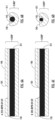
Figures 6A & 6B illustrates a longitudinal cut away view and bottom portion end view, respectively, of a section of an exemplary inner support tube with a protective wire inserted into the passageway thereof, wherein the inner support tube has defined therein a single side port opening at a 25% depth (radially inward) cut; and -
Figures 6C & 6D illustrates a longitudinal cut away view and bottom portion end view, respectively, of a section of an exemplary inner support tube with a protective wire inserted into the passageway thereof, wherein the inner support tube has defined therein a single side port opening at a 50% depth (radially inward) cut. - In the description, the terms "distal" or "proximal" are used in the following description with respect to a position or direction relative to the treating physician or medical interventionalist. "Distal" or "distally" are a position distant from or in a direction away from the physician or interventionalist. "Proximal" or "proximally" or "proximate" are a position near or in a direction toward the physician or medical interventionist. The terms "occlusion", "clot" or "blockage" are used interchangeably.
- During an endovascular treatment procedure (e.g., coil embolization), it is desirable for the system to reliably deliver and detach/deploy/deposit/release the implantable intravascular device (e.g., embolic coil) at a precise location or target site (e.g., aneurysm) within a vessel or artery. The implantable intravascular device (e.g., embolic coil) is releasably loaded on (e.g., secured to) the distal end of a delivery and detachment system that together as a unit are advanced to the desired target site in the vessel or artery. Releasable securement of the implantable intravascular device is via a securement wire (e.g., pull-wire) extending axially in a proximal direction through the delivery and detachment system. When the implantable intravascular device is precisely located at the target site in the artery or vessel the interventionalist applies sufficient force in a proximal direction on the securement wire to release (e.g., disengage) the implantable intravascular device for deposit at that location within the artery. Any shifting, translation, or movement of the securement wire during delivery of the implantable intravascular device may result in imprecise positioning and depositing offset from the intended target site in the artery or vessel.
- The present inventive delivery system minimizes or prevents unwanted translation, shifting, or movement of the securement wire during delivery of the implantable intravascular device to the target site in the artery by intentionally introducing or imposing a controlled friction force on the securement wire within an intentional friction zone.
-
Figure 1 is a longitudinal/axial cross-sectional view of an exemplary assembled delivery anddetachment system 100 in accordance with the present invention with an implantable intravascular device (e.g., embolic coil) 130 loaded thereto. Delivery anddetachment system 100 has aproximal end 105 and an oppositedistal end 110 to which the implantable intravascular device (e.g., embolic coil) 130 is releasably secured thereto.System 100 includes a main orouter delivery tube 115 having achannel 113 extending in a longitudinal/axial direction therethrough. Insertable into the distal end of thechannel 113 of themain delivery tube 115 is a proximal end of aninner support tube 140 which itself has apassageway 143 defined therethrough in a longitudinal/axial direction. A coil 120 (e.g., a helical coil) is disposed radially outward of the outer surface of theinner support tube 140. Anouter sleeve 135, preferably made of a lubricious reflowable material or a reflowable material having a lubricious outer coating, covers the outer surface of thecoil 120. By way of example, the outer sleeve is a thermoplastic elastomer (TPE) such as a polyether block amide (PEBA) known under the tradename of PEBAX®. In a preferred embodiment, at thedistal end 110 of the delivery anddetachment system 100 is disposed a compressible component (e.g., a helical detachment coil) 125 having an outer diameter larger than thecoil body 120, wherein theouter sleeve 135 stops proximally of (does not extend in an axial direction over or cover any portion of the compressible component 125). Similarly, theinner support tube 140 terminates proximally (i.e., does not extend into the cavity) of thecompressible component 125. - An implantable intravascular device (e.g., embolic coil) 130 is releasably connected to the
distal end 110 of the delivery anddetachment system 100 via aloop wire 155 threaded through an engagement device (e.g., proximal key) 160 disposed between the distal end of thecompressible component 125 and the proximal end of the implantableintravascular device 130. Respective free proximal ends of theloop wire 155 are permanently affixed to an inner surface of thecompressible component 125, whereas an opposite distal end ofloop wire 155 forms a closed loop. Engagement component (e.g., proximal key) 160 has an opening. As such, the implantableintravascular device 130 is releasably attached, connected, or secured to thedistal end 110 of the delivery anddetachment system 100 by bending a portion of the closed loop distal end of theloop wire 155 upwards (e.g., perpendicularly to the axial direction of the delivery and detachment system) through the opening of theengagement component 160 and threading the distal end of the securement wire (e.g., pull wire) 150 in a distal direction through the bent upwards closed loop distal end of theloop wire 155.Securement wire 150 is depicted as straight (i.e., extending or moving uniformly in one direction only; without a curve, kink, or bend); however, a non-straight, curved, kinked, or bent securement wire is possible to impart an even greater friction force. Engagement of the distal end of thesecurement wire 150 within the closed loop distal end of theloop wire 155 secures the engagement component (e.g., proximal key) 160 and implantable intravascular device (e.g., embolic coil) 130 attached distally thereto to the distal end of the delivery anddetachment system 100. - The implantable
intravascular device 130 is deployed, released, or deposited at a target stie in the artery by subjecting thesecurement wire 150 to an axial force in a proximal direction (e.g., pulling in a proximal direction). Sufficient axial force is applied in the proximal direction so that the distal end of thesecurement wire 150 is disengaged (i.e., free from, clear of, or no longer constrained by) theloop wire 155. Now released from theloop wire 155, thesecurement wire 150 is no longer connected to the engagement component (e.g., proximal key) 160 or implantableintravascular device 130 attached thereto. -
Compressible component 125 may initially be under compression subject to decompression/expansion once thesecurement wire 150 is disengaged from theloop wire 155 imparting a force in a distal direction on the proximal end of the implantable intravascular device (e.g., embolic coil) 130. Theloop wire 155 preferably has sufficient flexibility such that when the decompression/expansion force is imparted by thecompressible component 125 theloop wire 155 moves out of the opening of the engagement component (e.g., proximal key) 160 thereby detaching/releasing the implantableintravascular device 130 from thedelivery system 100. Moreover, the force imparted by thecompressible component 125 during decompression/expansion preferably pushes the implantableintravascular device 130 in a distal direction away from thedistal end 110 of thedelivery system 100 creating a predetermined separation distance therebetween upon deployment. Other purely mechanical (non-thermal and non-electrical) arrangements releasable upon application of an axial force in a proximal direction (e.g., pulling force) are contemplated and within the intended scope of the present invention for releasably securing the implantable intravascular device to the distal end of the delivery and detachment system. - A stretch
resistant element 163 is preferably disposed internally within the cavity of the implantableintravascular device 130. At a distal end, stretchresistant element 163 is secured via a bead or other stoppingcomponent 164 having an outer diameter that prevents passage in a proximal direction into the interior cavity of the implantableintravascular device 130, while its opposite proximal end is secured to the distal end of the engagement component 160 (e.g., threaded through an opening thereof). - For trackability during use one or more marker bands detectable through imaging may be provided along regions of one or more components of the delivery and detachment system. For instance,
marker bands main delivery tube 115 and a distal section of the coil body 120 (preferably aligned with that of theside port openings - In preparation of assembly of the components of the present inventive delivery and
detachment system 100, along a distal section of the inner support tube 140 a plurality of radially inward cuts are made extending from the outer surface through to (intersecting) thepassageway 143 creating a plurality ofside port openings 165 that allow a fluid (e.g., the reflowable material of the outer sleeve) to flow/seep therethrough. The term "distal section" is expressly defined as any section, region, portion, or area along the inner support tube that satisfies the following conditions: (i) in a distal direction relative to a midpoint between opposing proximal and distal ends/tips of the inner support tube; and (ii) in a proximal direction relative to the distal end/tip of the inner support tube. In other words, the selected distal section along which the intentional friction zone is created is located anywhere in a region between, without including either, the distal end/tip and the midpoint of the inner support tube. -
Figure 3A is a perspective view of an exemplary supporting and cuttingstructure 300 used to make radially inward skived cuts into an outer surface of theinner support tube 140 through to (intersecting) thepassageway 143 defined axially therein. Theinner support tube 140 in which the side openings are to be created is supported on thestructure 300 and held in position by a clamp 320 (Figures 3A &3D ). - A
side port template 309 having a plurality of troughs (305a, 305b, 305c) arranged parallel to one another in an X-direction define the location, spacing, arrangement and the angle of the cuts to be made to theinner support tube 140 to create theside port openings 165 having a desired geometric cross-sectional shape (e.g., trapezoidal shape). Three troughs (305a, 305b, 305c) are shown in the example represented inFigures 3A &3D all having the same cross-sectional shape (e.g., trapezoidal shape); however, the number, location, spacing, arrangement, and/or cross-sectional shape of each trough may be designed, as desired. - By way of example, adjacent side port openings defined in the
inner support tube 140 depicted inFigure 2A are separated from one another both in a longitudinal/axial direction and in a radial direction. That is,side port 165a is separated both in a longitudinal/axial direction and a radial direction (approximately 180°) relative to that ofadjacent side port 165b, as is true for all adjacent side port openings illustrated. Threeside port openings 165a-165c are illustrated inFigure 2A ; however, any number of two or more side port openings may be made, as desired. The geometric shape of each side port opening may be modified, as desired, so long as each side port opening extends radially inward through the inner support tube 140 (i.e., from its outer surface to its passageway 143). A controlled amount of intentionally introduced friction force imposed on thesecurement wire 150 when threaded through thepassageway 143 is produced by selecting: (i) the number of side port openings; (ii) the location and arrangement of the side port openings (both longitudinally/axially and radially); and (iii) the dimensions in an axial direction (Z-direction) and in a radial direction (X-direction) of each side port opening created in the inner support tube. - In the exemplary configuration of
Figure 2A , each side port opening of the inner support tube has an axial length of approximately 1mm, with at least approximately 1mm separation in an axial direction between adjacent side port openings. Continuing with this example, at a minimum there would be approximately 2mm distance in an axial direction from the proximal end of the first side port opening and the proximal end of the adjacent/next second side port opening. The spacing of cuts in a radial direction may be more compact depending on such factors as the depth (radially inward) of the cut and amount of remaining material (i.e., strength) of the inner support tube. Referring toFigures 6A-6D varying exemplary depth cuts are made to the inner support tube. Specifically,Figures 6A & 6B depict a longitudinal cut-away view and a bottom portion end view, respectively, of theinner support tube 140 having aside port opening 165 with a 25% depth (radially inward) cut, whereasFigures 6C & 6D depict the same views for a side port opening with a 50% depth (radially inward) cut. The deeper radial cut (50% depth) extending further radially inward into the clearance or free space within thepassageway 143 of theinner support tube 140 when a smaller diameter protective metal wire/mandrel 311 is used. - Prior to assembling the delivery and detachment system, the inner support tube is mechanically supported (held in place) on a supporting and cutting structure while the plurality of radially inward cuts are made to create the side port openings along the distal section thereof.
Figures 3A &3D depict an exemplary supporting and cuttingdevice 300 including asubstrate 301 and a corrugated/wave platform 308 having a plurality of longitudinally arranged parallel ridges andvalleys 303 extending along the Z-axis. Theinner support tube 140 in which the side port openings are to be created is placed within an associated one of the valleys (between adjacent ridges) 303 of the corrugated/wave platform 308 so that the longitudinal axis of theinner support tube 140 is arranged parallel with the Z-axis. Side port openings in more than one inner support tube may be cut simultaneously at the same time, wherein eachinner support tube 140 is placed within an associatedvalley 303 on the corrugated/wave platform 308 of the supporting and cuttingdevice 300. Supporting and cuttingdevice 300 further includes aside port template 309 having defined therein parallel to the Z-axis a series ofchannels 307 equal in number to that of thevalleys 303 of the corrugated/wave platform 308. Eachchannel 307 of theside port template 309 is aligned in a Z-direction with acorresponding valley 303 of the corrugated/wave platform 308. -
Side port template 309 has a plurality of troughs (e.g., recesses) 305a-305c defined therein parallel to one another and extending along an X-axis perpendicular to the Z-axis. The number oftroughs 305a-305c corresponds to the desired number of side port openings to be created in the inner support tube. Eachtrough channels 307 defined in theside port template 309 parallel with the Z-axis emerge on one side, extend across, and thereafter continue on the opposite side of each of the plurality oftroughs 305a-305c. Each trough preferably has a trapezoidal like cross-sectional shape parallel to the Z-axis (i.e., tapered sides widening in opposing directions from a flat bottom surface) connecting the narrowing free ends of the tapered sides), as shown inFigures 3B & 3C . The preferred range of angularity of the tapered sides of the notch is an acute angle α (e.g., less than 90°) relative to the Z-axis extending perpendicularly through thechannel 307. - Initially, the
inner support tube 140 in which the side port openings are to be created is placed/supported within one of thevalleys 303 of the corrugated/wave shape platform 308 and slid along the Z-direction into an associatedchannel 307 defined through the side port template 309 (Figure 3D ). With continued advancement in the Z-direction upon encountering eachtrough 305a the distal end of theinner support tube 140 emerges/exits from thechannel 307, advances across the associated trough, and once again is received in the channel that picks up on the opposite side of the trough. After advancing across the final or last trough, the distal end of the inner support tube is preferably threaded/received once again in the channel at the opposite side of the final/last trough to ensure that the distal most end of the inner support tube is supported/held within the channel while the side port openings are being cut. - Once fully inserted into a
corresponding channel 307 of theside port template 309, theinner support tube 140 is held in position on the supporting and cuttingdevice 300 via aclamp 320. With theinner support tube 140 secured in place on the supporting and cuttingdevice 300, aprotective wire 311 made of metal or some other material impenetrable by the blade is threaded through thepassageway 143 preventing piercing/penetrating of the blade through to the opposing side (180° opposite side) of the inner support tube when making the skived cuts.Figure 3E is an enlarged view of theinner support tube 140 extending across thetrapezoidal trough 305a of theside port template 309 depicting theprotective wire 311 as it is being advanced in a distal direction through thepassageway 143 thereof. - A blade 310 (e.g., razor blade) is receivable within an opening in a hinged mounting
arm 312 the angle of which may be adjusted, as desired, via arotating handle 315. Preferably, theblade 310 is secured in place using a conventional locking mechanism (e.g., tightening thumb screw) at an acute angle α (less than 90° relative to the Z-axis), substantially conforming to the angle of the tapered sides of the trapezoidal trough. Eachside port opening 165 is preferably made by two passes/cuts of the blade using the exemplary supporting and cutting device ofFigure 3A , insufficient reflow of the material reaching the passageway of the inner support tube to create the intended friction zone being achieved if only a single cut (slit) was made. A first pass/cut within one of the troughs is made with theblade 310 oriented at an acute angle α (less than 90° relative to the Z-axis), as shown inFigure 3B , for each location of the side port opening. Thereafter, therotating handle 315 is adjusted 180° (flipped horizontally) (as shown inFigure 3C ) at which position the second pass/cut is made with the blade to complete that particular side port opening. With the second pass/cut of the blade a piece (wedge) of the inner support tube bounded on either side by the respective passes/cuts is lifted or removed revealing the side port formed therein (and the now visible passageway). This process is repeated for each of the plurality of side ports desired in the distal section of the inner support tube. Referring toFigure 3A ,troughs side port openings side port opening 165b may be created usingtrough 305b (after rotating theinner support tube 140 by 180°). Trapezoidal shape side cuts are preferred over a perpendicular cut relative to the X-axis to ensure that the size of the side port opening is sufficient to allow sufficient material to reflow/seep therethrough and into the passageway. - Using a blade (e.g., a razor blade, knife, or other cutting device) 310 a plurality of radially inward cuts, preferably skived cuts, are made along the distal section or region of the
inner support tube 140 to create theside port openings 165a-165c. Each radially inward skived cut removes a portion of the outer surface of theinner support tube 140 through to the longitudinal/axial passageway 143 extending from its proximal end/tip to its opposite distal end/tip. - The number of side port openings and width (along the Z-axis) of each side port opening may be modified, as desired. Each side port opening may have a uniform shape and size or vary, as desired.
Inner support tube 140 prevents or minimizes stretch resistance of thesecurement wire 150 within thedelivery system 100. Thus, the shape and size of the side port opening is selected with several competing considerations in mind. On the one hand, the side port opening is sufficient in size to allow reflow/seepage of the reflowable outer sleeve material and creation of a controlled amount of friction force on the securement wire. While, on the other hand, the wider the side port opening the weaker the ability of the inner support tube to provide such resistance. - The present inventive inner support tube has been shown and described as having a plurality of side port openings defined therein with each side port opening being formed from two skived cuts. The angle of the single cut may be at any desired angle α in a range of 90° (relative to the Y-axis) ≥ α >0° (
Figure 3C ). - With the desired number of side port openings created, following withdraw of the
protective wire 311 from the passageway 143 (as illustrated inFigure 3F ), theinner support tube 140 comprising part of the present inventive delivery and detachment system is ready to be assembled. Specifically, theinner support tube 140 with theside port openings coil 120. No portion of theinner support tube 140 extends in a longitudinal direction into the inner cavity of thecompressible element 125, i.e., each of theside port openings 165 are disposed proximally of and separated a predetermined distance relative to thecompressible element 125. The outer sleeve or covering 135 is positioned about or covering the outer surface of thecoil 120. For illustrative purposes only, theinner support sleeve 140 is first inserted into thecoil 120 which together as a unit are received within theouter sleeve 135. It is, however, also within the intended scope of the present invention to insert thecoil 120 within theouter sleeve 135 to form a unit together and thereafter insert theinner support tube 140 into the inner cavity formed by thecoil 120 that forms a unit with theouter sleeve 135. Thus, the order of assembly of these three components (e.g., the inner support tube 140 (with the side port openings defined in the distal section or region thereof); thecoil 120; and the outer sleeve 135) may be selected, as desired, and is within the intended scope of the prevent invention. - A straight mandrel is inserted in a longitudinal direction through the passageway of the
inner support tube 140 after being assembled together with thecoil 120 andouter sleeve 135. The straight mandrel is heated to a prescribed fusing temperature to cause theouter sleeve 135 material (e.g., polyether block amide (PEBA) or other thermoplastic polymer) to reflow over the outer surface of the inner support tube 140 (made of a thermoplastic polymer material that does not melt at that temperature such as polyether ether ketone (PEEK)), radially inward through theside port openings 165a-165c, and partially into (along the inner wall of) thepassageway 143. Thus, in the areas where the outer sleeve material seeps into the passageway the inner diameter of the passageway of the inner support tube is reduced. The dimensions of theside port openings 165a-165c are selected to allow sufficient reflow of the material of theouter sleeve 135 to seep into thepassageway 143 of theinner support tube 140 and create a controlled amount of friction force when directly physically contacting or directly engaging with thesecurement wire 150 threaded therethrough. By way of illustrative example, the preferred range of outer diameter of the mandrel is in a range of approximately 70% - approximately 80% of the inner diameter of the passageway of the inner support tube. In experimental testing, the outer diameter of the mandrel is 0.003 in. creating an intentional friction zone within a range of approximately 10 gF to approximately 20 gF to maintain the position of the securement wire in the delivery and detachment system during use. - In addition to the friction force resulting from the reduced or decreased inner diameter of the
passageway 143 of theinner support tube 140 created by the reflow of the outer sleeve material through the side port openings into the passageway, an additional contribution to the friction force imposed on thesecurement wire 150 may be produced by the frictional characteristics of the reflow material itself of the outer sleeve upon contacting with the outer surface of the mandrel. In this regard, the mandrel used to reflow the outer sleeve material through the side port openings created in the inner support tube may be either coated (i.e., a mandrel coated with a lubricious coating) or non-coated (i.e., a mandrel not coated with a lubricious coating). In the case of a non-coated (free of any lubricious coating) mandrel the reflowed outer sleeve material adheres along the entire outer surface of the mandrel providing a predetermined amount of tacking force desirably contributing to the controlled friction force imposed on the outer surface of the securement wire. Even when using a mandrel coated with a lubricious material (e.g., Polytetrafluoroethylene (PTFE)), portions, sections, or regions of the outer surface of the mandrel exposed or lacking the coating will nevertheless exist producing patches in which a tacking force is produced. In the case of the coated mandrel, the tacking force is generated only in those random areas where the coating happens to be omitted, missing, or not present on the outer surface of the mandrel, whereas the tacking force produced when employing a non-coated mandrel extends substantially over the entire outer surface of the mandrel. - After the prescribed exposure time to the heat temperature has expired (for example, 420°F for a period of 5 sec. - 30 sec.) withdraw of the mandrel from the three-component assembly (
outer sleeve 135,coil 120; and inner support tube 140) allows cooling and hardening of the material of theouter sleeve 135 that has seeped through the side port openings into thepassageway 143 of theinner support tube 140. Next, thesecurement wire 143 secured at its distal end to a distal assembly comprising thedetachment coil 125,proximal key 160 and implantableintravascular device 130 is threaded in a proximal direction through thepassageway 143 of the three-component assembly (reflowedouter sleeve 130,coil 120, and inner support tube 140). - A
main delivery tube 115 having achannel 113 defined in a longitudinal/axial direction therethrough is assembled to the proximal end of the thus assembled delivery and detachment system. Specifically, the proximal end of theinner support tube 140 extends in a proximal direction beyond the proximal end of the of thecoil 120 and is sized to be telescopically receivable in thechannel 113 of themain delivery tube 115. The threading of thesecurement wire 150 continues in a proximal direction through thechannel 113 of themain delivery tube 115 and alumen 170 of a proximalinner tube 145 whose distal end is received within thechannel 113. A portion of the proximal end of the proximalinner tube 145 extends in a proximal direction relative to the proximal end of themain delivery tube 115. The proximal end of the securement wire that has been threaded in a proximal direction rough thelumen 170 of the proximalinner tube 145 and thechannel 113 of themain delivery tube 115 is non-releasably secured (e.g., welded) 175 to the proximal end of the proximalinner tube 145. - In use, a catheter or microcatheter is navigated through the artery to the proximal side of the target site (e.g., aneurysm). Thereafter, using the assembled delivery and detachment system (as shown in
Figure 1 ) the implantableintravascular device 130 releasably secured to the distal end thereof is advanced through the catheter or microcatheter to the target site. During delivery of the implantableintravascular device 130 by the interventionalist (prior to deployment) undesirable shifting, movement or translation of the securement wire is prevented or minimized by intentionally imposing a controlled friction force on a radially outward surface along a distal section of thesecurement wire 150 where it directly physically contacts the reflowed material of theouter sleeve 135 that has seeped through theside port openings 165 of theinner support tube 120 and into thepassageway 143 thereof. The amount of friction force imposed is sufficient to prevent or minimize shifting, movement or translation of the securement wire in the passageway during delivery able to be overcome only by application of sufficient axial force in a proximal direction on the securement wire when deploying (releasing) the implantable intravascular device from the delivery and detachment system to be precisely and accurately deposited at the target site in the artery. - The design described above and illustrated narrows the inner diameter of the passageway defined in the inner support tube by reflow of the outer sleeve material through side port openings defined therein and into the passageway to intentionally narrow the inner diameter along those areas imposing a controlled friction force on the outer surface of the securement wire threaded therethrough. Other mechanical configurations to intentionally introduce a controlled friction force on the outer surface of the securement wire are contemplated and within the intended scope of the present invention. Rather than alter the structure of the inner support tube (e.g., creating the side port openings in and reducing the inner diameter of the passageway thereof) the design of the securement wire along a distal section thereof may be modified. In this regard, a bend or kink in the otherwise substantially linear may be made along a distal section of the securement wire to intentionally create one or more points/sections/areas/regions of direct physical contact between the
securement wire 150 and the inner wall of thepassageway 143 of theinner support tube 140. For instance, the securement wire 140' inFigure 5 intentionally includes multiple bends or kinks configured as a trapezoidal shape establishing direct physical regions of contact of the securement wire with the inner wall of the passageway (approximately 180° radially from one another) resulting in the imposition of an intentional controlled friction force. Alternative configurations in the bending or kinking of the securement wire forming a variety of geometric shapes are contemplated and within the intended scope of the present invention. The number of, overall surface area, and/or spacing between points/sections/areas/regions of forced or intentional direct physical contact between the securement wire and the inner wall of the lumen of the inner support tube may be selected, as desired, to achieve a controlled intentional friction force on the securement wire when assembled within the delivery and detachment system. Once again keeping in mind that, on the one hand, the intentional controlled friction force imposed by the bent or kinked securement wire directly engaging with the inner wall of the passageway of the inner support tube is sufficient to prevent or minimize shifting, translation or movement of the securement wire during delivery of the implantable intravascular device. Yet, on the other hand, upon application of sufficient force in a proximal direction on thesecurement wire 140 the intentional controlled friction force is overcome releasing the implantableintravascular device 130 from the delivery and detachment system. - Regardless of the particular mechanical design of the way in which the assembled delivery and detachment system creates an intentional friction zone, the controlled amount of friction force imposed on the securement wire when assembled in the delivery and detachment system may be modified, as desired, to prevent or minimize shifting, translation, or movement of the securement wire during delivery and detachment of the implantable intravascular device, yet able to be overcome when sufficient force is applied in a proximal direction on the securement wire to release the implantable intravascular device. The present invention has been shown and described with respect to a delivery and detachment system loaded with an embolic coil during a coil embolization procedure in the treatment of an intracranial aneurysm. It is contemplated and within the intended scope of the present invention to utilize the present inventive delivery and detachment system for other types of implantable intravascular devices used in other endovascular treatment procedures.
- Thus, while there have been shown, described, and pointed out fundamental novel features of the invention as applied to a preferred embodiment thereof, it will be understood that various omissions, substitutions, and changes in the form and details of the systems/devices illustrated, and in their operation, may be made by those skilled in the art without departing from the spirit and scope of the invention. For example, it is expressly intended that all combinations of those elements and/or steps that perform substantially the same function, in substantially the same way, to achieve the same results be within the scope of the invention. Substitutions of elements from one described embodiment to another are also fully intended and contemplated. It is also to be understood that the drawings are not necessarily drawn to scale, but that they are merely conceptual in nature. It is the intention, therefore, to be limited only as indicated by the scope of the claims appended hereto.
- Every issued patent, pending patent application, publication, journal article, book or any other reference cited herein is each incorporated by reference in their entirety.
- Aspects of the invention:
- 1. A method of using a delivery and detachment system for an implantable intravascular treatment device; the delivery and detachment system including an inner support tube having a passageway extending in an axial direction between a proximal end and an opposite distal end; and the delivery; and detachment system further including a securement wire extending through the passageway of the inner support tube; imposed on the securement wire is a controlled friction force established within an intentional friction zone located anywhere between the distal end of the inner support tube and a midway point between the respective proximal and distal ends of the inner support tube, the method comprising the steps of:
- during delivery of the implantable intravascular treatment device to a target site, the imposed controlled friction force minimizing movement of the securement wire relative to the inner support tube; and
- upon the implantable intravascular treatment device reaching the target site, applying a force in a proximal direction on the securement wire sufficient to exceed the imparted controlled friction force and releasing the implantable intravascular device from the delivery and detachment system.
- 2. The method according to
aspect 1, wherein the delivery and detachment system includes: an outer sleeve surrounding an outer surface of the inner support tube, wherein the outer sleeve is made of a reflowable material; wherein the inner support tube has defined therein at least one radially inward side port opening intersecting with the passageway; and the reflowable material of the outer sleeve seeped through the at least one radially inward side port opening defined in the inner support tube and into the passageway of the inner support tube forming an associated point of direct physical contact with the securement wire. - 3. The method according to aspect 2, wherein the delivery and detachment system further includes a coil disposed between the inner support tube and the outer sleeve.
- 4. The method according to
aspect 1, wherein the securement wire is straight. - 5. The method according to
aspect 1, wherein the securement wire has at least one bend therein each bend directly physically contacting the reflowable material of the outer sleeve that has seeped into the passageway of the inner support tube. - 6. The method according to
aspect 1, wherein the passageway of the inner support tube has a uniform inner diameter and the securement wire has at least one bend therein, each of the at least one bend directly physically contacting the inner wall of the passageway of the inner support tube creating the controlled friction force.
Claims (12)
- A delivery and detachment system for an implantable intravascular device, the system comprising:an inner support tube having a passageway extending in an axial direction from a proximal end to an opposite distal end; anda securement wire extending through the passageway of the inner support tube;imposed on the securement wire is a controlled friction force established within an intentional friction zone located anywhere between the distal end of the inner support tube and a midway point between the respective proximal and distal ends of the inner support tube.
- The delivery and detachment system according to claim 1, further comprising and outer sleeve surrounding an outer surface of the inner support tube, wherein the outer sleeve is made of a reflowable material; wherein the inner support tube has defined therein at least one radially inward side port opening intersecting with the passageway; and the reflowable material of the outer sleeve being seepable through the at least one radially inward side port opening defined in the inner support tube and into the passageway of the inner support tube forming an associated point of direct physical contact with the securement wire.
- The delivery and detachment system according to claim 2, further comprising a coil disposed between the inner support tube and the outer sleeve; the relowable material of the outer sleeve being seepable through the coil.
- The delivery and detachment system according to claim 2, wherein the securement wire is straight.
- The delivery and detachment system according to claim 2, wherein the securement wire has at least one bend therein each bend directly physically contacting the reflowable material of the outer sleeve that has seeped into the passageway of the inner support tube.
- The delivery and detachment system in accordance with claim 1, wherein the passageway of the inner support tube has a uniform inner diameter and the securement wire has at least one bend therein wherein each bend directly physically contacting the inner wall of the passageway of the inner support tube.
- The system in accordance with claim 1, wherein the implantable intravascular device is releasably secured to a distal end of the delivery and detachment system via the securement wire.
- The system in accordance with claim 1, further comprising:a main delivery tube having a proximal end, an opposite distal end, and a channel extending axially therebetween; the proximal end of the inner support tube telescopically received in the channel at the distal end of the main delivery tube; anda proximal retaining tube having a proximal end, an opposite distal end and a lumen extending in an axial direction therebetween; the securement wire extending through the lumen and secured to the proximal end of the proximal retaining tube; the distal end of the proximal retaining tube telescopically received in the proximal end of the main delivery tube.
- A method for manufacture of a delivery and detachment system for an implantable intravascular device, the method comprising the steps of:providing an inner support tube having a passageway extending in an axial direction from a proximal end to an opposite distal end;as a securement wire is being threaded through the passageway of the inner support tube, imposing on the securement wire a controlled friction force established within an intentional friction zone located anywhere between the distal end of the inner support tube and a midway point between the respective proximal and distal ends of the inner support tube.
- The method according to claim 9, wherein the imposing step comprises the steps of:creating at least one side port opening in the inner support tube; each of the at least one side openings extending radially inward and intersecting with the passageway of the inner support tube;assembling an outer sleeve made of a reflowable material about the coil to create an assembly;heating of the assembly so the reflowable material of the outer sleeve seeps through the at least one side port opening into the passageway of the inner support tube creating the intentional friction zone; wherein along an associated point the securement wire being in direct physical contact with the reflowable material of the outer sleeve that has seeped into the passageway.
- The method according to claim 10, wherein a coil is positioned radially about the inner support tube with the at least one side port opening created therein.
- The method according to claim 9, wherein the passageway of the inner support tube is uniform and the securement wire has at least one bend therein, each of the at least one bend directly physically contacting an inner wall of the passageway of the inner support tube creating the controlled friction force.
Applications Claiming Priority (1)
| Application Number | Priority Date | Filing Date | Title |
|---|---|---|---|
| US17/569,620 US12220131B2 (en) | 2022-01-06 | 2022-01-06 | Delivery and detachment system imposing a friction force on a securement wire to minimize movement of an implantable intravascular device |
Publications (3)
| Publication Number | Publication Date |
|---|---|
| EP4209183A1 true EP4209183A1 (en) | 2023-07-12 |
| EP4209183B1 EP4209183B1 (en) | 2025-05-07 |
| EP4209183C0 EP4209183C0 (en) | 2025-05-07 |
Family
ID=84829849
Family Applications (1)
| Application Number | Title | Priority Date | Filing Date |
|---|---|---|---|
| EP23150411.9A Active EP4209183B1 (en) | 2022-01-06 | 2023-01-05 | Delivery and detachment system imposing a friction force on a securement wire to minimize movement of an implantable intravascular device |
Country Status (6)
| Country | Link |
|---|---|
| US (1) | US12220131B2 (en) |
| EP (1) | EP4209183B1 (en) |
| JP (1) | JP2023100596A (en) |
| KR (1) | KR20230106522A (en) |
| CN (1) | CN116392183A (en) |
| ES (1) | ES3034482T3 (en) |
Citations (7)
| Publication number | Priority date | Publication date | Assignee | Title |
|---|---|---|---|---|
| US20080306504A1 (en) * | 2006-11-20 | 2008-12-11 | Thazin Win | Mechanically detachable vaso-occlusive device |
| US20110060360A1 (en) * | 2004-07-30 | 2011-03-10 | Codman & Shurtleff, Inc. | Embolic Device Delivery System With Retractable Partially Coiled-Fiber Release |
| US20150057698A1 (en) * | 2013-08-22 | 2015-02-26 | Cook Medical Technologies Llc | Detachable treatment device delivery system with narrowed diameter region at attachment zone |
| US20150216688A1 (en) * | 2014-02-04 | 2015-08-06 | The Texas A&M University System | Intravascular Medical Device Release System |
| US20200229957A1 (en) * | 2016-07-29 | 2020-07-23 | Wallaby Medical, Inc. | Implant delivery systems and methods |
| US20210085498A1 (en) * | 2019-09-24 | 2021-03-25 | Boston Scientific Scimed, Inc. | Medical device release system |
| US11457922B2 (en) * | 2020-01-22 | 2022-10-04 | DePuy Synthes Products, Inc. | Medical device delivery member with flexible stretch resistant distal portion |
Family Cites Families (112)
| Publication number | Priority date | Publication date | Assignee | Title |
|---|---|---|---|---|
| US8252040B2 (en) | 2001-07-20 | 2012-08-28 | Microvention, Inc. | Aneurysm treatment device and method of use |
| US8715312B2 (en) | 2001-07-20 | 2014-05-06 | Microvention, Inc. | Aneurysm treatment device and method of use |
| US7371228B2 (en) | 2003-09-19 | 2008-05-13 | Medtronic Vascular, Inc. | Delivery of therapeutics to treat aneurysms |
| US9308382B2 (en) | 2004-06-10 | 2016-04-12 | Medtronic Urinary Solutions, Inc. | Implantable pulse generator systems and methods for providing functional and/or therapeutic stimulation of muscles and/or nerves and/or central nervous system tissue |
| US9655633B2 (en) | 2004-09-10 | 2017-05-23 | Penumbra, Inc. | System and method for treating ischemic stroke |
| US20060089637A1 (en) | 2004-10-14 | 2006-04-27 | Werneth Randell L | Ablation catheter |
| US8562672B2 (en) | 2004-11-19 | 2013-10-22 | Medtronic, Inc. | Apparatus for treatment of cardiac valves and method of its manufacture |
| US9636115B2 (en) | 2005-06-14 | 2017-05-02 | Stryker Corporation | Vaso-occlusive delivery device with kink resistant, flexible distal end |
| EP1895927A4 (en) | 2005-06-20 | 2011-03-09 | Medtronic Ablation Frontiers | Ablation catheter |
| US8066036B2 (en) | 2005-11-17 | 2011-11-29 | Microvention, Inc. | Three-dimensional complex coil |
| US9757260B2 (en) | 2006-03-30 | 2017-09-12 | Medtronic Vascular, Inc. | Prosthesis with guide lumen |
| US9615832B2 (en) | 2006-04-07 | 2017-04-11 | Penumbra, Inc. | Aneurysm occlusion system and method |
| CA2655026C (en) | 2006-06-15 | 2016-08-02 | Microvention, Inc. | Embolization device constructed from expansible polymer |
| WO2009086208A2 (en) | 2007-12-21 | 2009-07-09 | Microvention, Inc. | Hydrogel filaments for biomedical uses |
| US8974518B2 (en) | 2008-03-25 | 2015-03-10 | Medtronic Vascular, Inc. | Eversible branch stent-graft and deployment method |
| WO2009135075A1 (en) | 2008-04-30 | 2009-11-05 | Medtronic, Inc. | Techniques for placing medical leads for electrical stimulation of nerve tissue |
| US8070694B2 (en) | 2008-07-14 | 2011-12-06 | Medtronic Vascular, Inc. | Fiber based medical devices and aspiration catheters |
| US8333796B2 (en) | 2008-07-15 | 2012-12-18 | Penumbra, Inc. | Embolic coil implant system and implantation method |
| US8475431B2 (en) * | 2008-07-18 | 2013-07-02 | Cook Medical Technologies Llc | Introducer sheath having a braided member and methods of manufacture |
| US8721714B2 (en) | 2008-09-17 | 2014-05-13 | Medtronic Corevalve Llc | Delivery system for deployment of medical devices |
| JP5608731B2 (en) | 2009-04-15 | 2014-10-15 | マイクロベンション インコーポレイテッド | Implant delivery system |
| WO2011038017A1 (en) | 2009-09-22 | 2011-03-31 | Penumbra, Inc. | Manual actuation system for deployment of implant |
| CA2795740C (en) | 2010-04-14 | 2018-03-13 | Microvention, Inc. | Implant delivery device |
| US8764811B2 (en) | 2010-04-20 | 2014-07-01 | Medtronic Vascular, Inc. | Controlled tip release stent graft delivery system and method |
| US8876878B2 (en) | 2010-07-23 | 2014-11-04 | Medtronic, Inc. | Attachment mechanism for stent release |
| US8616040B2 (en) | 2010-09-17 | 2013-12-31 | Medtronic Vascular, Inc. | Method of forming a drug-eluting medical device |
| WO2012088162A1 (en) | 2010-12-20 | 2012-06-28 | Microvention, Inc. | Polymer stents and methods of manufacture |
| US9486604B2 (en) | 2011-05-12 | 2016-11-08 | Medtronic, Inc. | Packaging and preparation tray for a delivery system |
| WO2012158668A1 (en) | 2011-05-17 | 2012-11-22 | Stryker Corporation | Method of fabricating an implantable medical device that includes one or more thin film polymer support layers |
| WO2012166467A1 (en) | 2011-05-27 | 2012-12-06 | Stryker Corporation | Assembly for percutaneously inserting an implantable medical device, steering the device to a target location and deploying the device |
| US9750565B2 (en) | 2011-09-30 | 2017-09-05 | Medtronic Advanced Energy Llc | Electrosurgical balloons |
| CA2867181C (en) | 2012-03-16 | 2020-08-11 | Microvention, Inc. | Stent and stent delivery device |
| US9833625B2 (en) | 2012-03-26 | 2017-12-05 | Medtronic, Inc. | Implantable medical device delivery with inner and outer sheaths |
| US9717421B2 (en) | 2012-03-26 | 2017-08-01 | Medtronic, Inc. | Implantable medical device delivery catheter with tether |
| US9242290B2 (en) | 2012-04-03 | 2016-01-26 | Medtronic Vascular, Inc. | Method and apparatus for creating formed elements used to make wound stents |
| US9700399B2 (en) | 2012-04-26 | 2017-07-11 | Medtronic Vascular, Inc. | Stopper to prevent graft material slippage in a closed web stent-graft |
| US9549832B2 (en) | 2012-04-26 | 2017-01-24 | Medtronic Vascular, Inc. | Apparatus and methods for filling a drug eluting medical device via capillary action |
| US9149190B2 (en) | 2012-07-17 | 2015-10-06 | Stryker Corporation | Notification system of deviation from predefined conditions |
| US9770251B2 (en) | 2012-08-13 | 2017-09-26 | Microvention, Inc. | Shaped removal device |
| US9504476B2 (en) | 2012-10-01 | 2016-11-29 | Microvention, Inc. | Catheter markers |
| BR112015008245B1 (en) | 2012-10-15 | 2022-09-27 | Microvention, Inc | POLYMERIC TREATMENT COMPOSITIONS |
| US9539022B2 (en) | 2012-11-28 | 2017-01-10 | Microvention, Inc. | Matter conveyance system |
| WO2014089392A1 (en) | 2012-12-07 | 2014-06-12 | Medtronic, Inc. | Minimally invasive implantable neurostimulation system |
| US9539382B2 (en) | 2013-03-12 | 2017-01-10 | Medtronic, Inc. | Stepped catheters with flow restrictors and infusion systems using the same |
| EP3009084B1 (en) | 2013-03-14 | 2017-09-13 | Stryker Corporation | Vaso-occlusive device delivery system |
| US9539011B2 (en) | 2013-03-14 | 2017-01-10 | Stryker Corporation | Vaso-occlusive device delivery system |
| EP2967572B1 (en) | 2013-03-14 | 2019-04-24 | Stryker Corporation | Vaso-occlusive device delivery system |
| JP6636908B2 (en) | 2013-03-15 | 2020-01-29 | テルモ株式会社 | Embolism prevention device |
| US9833252B2 (en) | 2013-03-15 | 2017-12-05 | Microvention, Inc. | Multi-component obstruction removal system and method |
| US9398966B2 (en) | 2013-03-15 | 2016-07-26 | Medtronic Vascular, Inc. | Welded stent and stent delivery system |
| WO2014174437A1 (en) | 2013-04-22 | 2014-10-30 | Sandvik Intellectual Property Ab | Method for drug loading hydroxyapatite coated implant surfaces |
| US9445928B2 (en) | 2013-05-30 | 2016-09-20 | Medtronic Vascular, Inc. | Delivery system having a single handed deployment handle for a retractable outer sheath |
| US9675782B2 (en) | 2013-10-10 | 2017-06-13 | Medtronic Vascular, Inc. | Catheter pull wire actuation mechanism |
| US9913961B2 (en) * | 2013-10-24 | 2018-03-13 | St. Jude Medical, Cardiology Division, Inc. | Flexible catheter shaft and method of manufacture |
| US9955978B2 (en) | 2013-10-25 | 2018-05-01 | Medtronic Vascular, Inc. | Tissue compression device with multi-chamber bladder |
| CA2934555C (en) | 2013-12-20 | 2020-07-07 | Microvention, Inc. | Device delivery system |
| US9833604B2 (en) | 2013-12-20 | 2017-12-05 | Microvention, Inc. | Delivery adapter |
| JP2017504390A (en) * | 2013-12-24 | 2017-02-09 | セント・ジュード・メディカル,カーディオロジー・ディヴィジョン,インコーポレイテッド | A deflectable catheter body having a corrugated structure |
| EP3128962B1 (en) | 2014-04-08 | 2018-05-23 | Stryker Corporation | Implant delivery system |
| WO2015167997A1 (en) | 2014-04-30 | 2015-11-05 | Stryker Corporation | Implant delivery system and method of use |
| US9060777B1 (en) | 2014-05-28 | 2015-06-23 | Tw Medical Technologies, Llc | Vaso-occlusive devices and methods of use |
| US9668898B2 (en) | 2014-07-24 | 2017-06-06 | Medtronic Vascular, Inc. | Stent delivery system having dynamic deployment and methods of manufacturing same |
| US9770577B2 (en) | 2014-09-15 | 2017-09-26 | Medtronic Xomed, Inc. | Pressure relief for a catheter balloon device |
| US9579484B2 (en) | 2014-09-19 | 2017-02-28 | Medtronic Vascular, Inc. | Sterile molded dispenser |
| US9692557B2 (en) | 2015-02-04 | 2017-06-27 | Stryker European Holdings I, Llc | Apparatus and methods for administering treatment within a bodily duct of a patient |
| US10307168B2 (en) | 2015-08-07 | 2019-06-04 | Terumo Corporation | Complex coil and manufacturing techniques |
| US10154905B2 (en) | 2015-08-07 | 2018-12-18 | Medtronic Vascular, Inc. | System and method for deflecting a delivery catheter |
| EP3334354B1 (en) | 2015-08-11 | 2021-03-03 | Terumo Corporation | System for implant delivery |
| EP3349689B1 (en) | 2015-09-18 | 2023-12-27 | Microvention, Inc. | Implant retention, detachment, and delivery system |
| JP6816126B2 (en) | 2015-09-18 | 2021-01-20 | マイクロベンション インコーポレイテッドMicrovention, Inc. | Releasable delivery system |
| CN108156803B (en) | 2015-09-18 | 2021-05-04 | 泰尔茂株式会社 | Pushable Implant Delivery System |
| JP6816127B2 (en) | 2015-09-18 | 2021-01-20 | テルモ株式会社 | Vascular prosthesis |
| ES2788738T3 (en) | 2015-09-21 | 2020-10-22 | Stryker Corp | Embolectomy devices |
| CN108024821B (en) | 2015-09-21 | 2020-10-30 | 斯瑞克公司 | embolectomy device |
| US10172632B2 (en) | 2015-09-22 | 2019-01-08 | Medtronic Vascular, Inc. | Occlusion bypassing apparatus with a re-entry needle and a stabilization tube |
| WO2017062383A1 (en) | 2015-10-07 | 2017-04-13 | Stryker Corporation | Multiple barrel clot removal devices |
| US10327791B2 (en) | 2015-10-07 | 2019-06-25 | Medtronic Vascular, Inc. | Occlusion bypassing apparatus with a re-entry needle and a distal stabilization balloon |
| US10786302B2 (en) | 2015-10-09 | 2020-09-29 | Medtronic, Inc. | Method for closure and ablation of atrial appendage |
| US10271873B2 (en) | 2015-10-26 | 2019-04-30 | Medtronic Vascular, Inc. | Sheathless guide catheter assembly |
| US20170147765A1 (en) | 2015-11-19 | 2017-05-25 | Penumbra, Inc. | Systems and methods for treatment of stroke |
| US10631946B2 (en) | 2015-11-30 | 2020-04-28 | Penumbra, Inc. | System for endoscopic intracranial procedures |
| WO2017100472A1 (en) | 2015-12-09 | 2017-06-15 | Medtronic Vascular Inc. | Catheter with a lumen shaped as an identification symbol |
| US10159568B2 (en) | 2015-12-14 | 2018-12-25 | Medtronic, Inc. | Delivery system having retractable wires as a coupling mechanism and a deployment mechanism for a self-expanding prosthesis |
| US10500046B2 (en) | 2015-12-14 | 2019-12-10 | Medtronic, Inc. | Delivery system having retractable wires as a coupling mechanism and a deployment mechanism for a self-expanding prosthesis |
| US10743883B2 (en) | 2015-12-30 | 2020-08-18 | Stryker European Holdings I, Llc | Embolic devices and methods of manufacturing same |
| US20170189033A1 (en) | 2016-01-06 | 2017-07-06 | Microvention, Inc. | Occlusive Embolic Coil |
| US10070950B2 (en) | 2016-02-09 | 2018-09-11 | Medtronic Vascular, Inc. | Endoluminal prosthetic assemblies, and associated systems and methods for percutaneous repair of a vascular tissue defect |
| AU2017217879B9 (en) | 2016-02-10 | 2021-08-19 | Microvention, Inc. | Intravascular treatment site access |
| AU2017218115B2 (en) | 2016-02-10 | 2020-03-05 | Microvention, Inc. | Devices for vascular occlusion |
| US10188500B2 (en) | 2016-02-12 | 2019-01-29 | Medtronic Vascular, Inc. | Stent graft with external scaffolding and method |
| EP4112111A1 (en) | 2016-03-31 | 2023-01-04 | Medtronic Vascular Inc. | Expandable introducer sheath |
| US20170281331A1 (en) | 2016-03-31 | 2017-10-05 | Medtronic Vascular, Inc. | Endoluminal prosthetic devices having fluid-absorbable compositions for repair of a vascular tissue defect |
| US10695542B2 (en) | 2016-04-04 | 2020-06-30 | Medtronic Vascular, Inc. | Drug coated balloon |
| US10252024B2 (en) | 2016-04-05 | 2019-04-09 | Stryker Corporation | Medical devices and methods of manufacturing same |
| US10441407B2 (en) | 2016-04-12 | 2019-10-15 | Medtronic Vascular, Inc. | Gutter filling stent-graft and method |
| US9987122B2 (en) | 2016-04-13 | 2018-06-05 | Medtronic Vascular, Inc. | Iliac branch device and method |
| US10010403B2 (en) | 2016-04-18 | 2018-07-03 | Medtronic Vascular, Inc. | Stent-graft prosthesis and method of manufacture |
| US20170304097A1 (en) | 2016-04-21 | 2017-10-26 | Medtronic Vascular, Inc. | Stent-graft delivery system having an inner shaft component with a loading pad or covering on a distal segment thereof for stent retention |
| JP6934935B2 (en) | 2016-04-25 | 2021-09-15 | ストライカー コーポレイションStryker Corporation | Inverted mechanical thrombectomy and intravascular use |
| US10517711B2 (en) | 2016-04-25 | 2019-12-31 | Medtronic Vascular, Inc. | Dissection prosthesis system and method |
| US10940294B2 (en) | 2016-04-25 | 2021-03-09 | Medtronic Vascular, Inc. | Balloon catheter including a drug delivery sheath |
| JP6924256B2 (en) | 2016-04-25 | 2021-08-25 | ストライカー コーポレイションStryker Corporation | Pre-installed reversing tractor thrombectomy device and method |
| ES2859656T3 (en) | 2016-04-25 | 2021-10-04 | Stryker Corp | Anti-jam and macerant thrombectomy appliances |
| US10406011B2 (en) | 2016-04-28 | 2019-09-10 | Medtronic Vascular, Inc. | Implantable medical device delivery system |
| US11147952B2 (en) | 2016-04-28 | 2021-10-19 | Medtronic Vascular, Inc. | Drug coated inflatable balloon having a thermal dependent release layer |
| US10191615B2 (en) | 2016-04-28 | 2019-01-29 | Medtronic Navigation, Inc. | Method and apparatus for image-based navigation |
| US10292844B2 (en) | 2016-05-17 | 2019-05-21 | Medtronic Vascular, Inc. | Method for compressing a stented prosthesis |
| CN113648518B (en) | 2016-06-01 | 2023-10-20 | 微仙美国有限公司 | Improved reinforced balloon catheter |
| JP6980703B2 (en) | 2016-06-03 | 2021-12-15 | ストライカー コーポレイションStryker Corporation | Inverting thrombectomy device |
| US10588495B2 (en) * | 2016-07-28 | 2020-03-17 | Cook Medical Technologies LL | Brake mechanism of a steerable catheter |
| US10537710B2 (en) * | 2017-04-20 | 2020-01-21 | Covidien Lp | Catheter including an inner liner with a flexible distal section |
| US11766539B2 (en) * | 2019-03-29 | 2023-09-26 | Incept, Llc | Enhanced flexibility neurovascular catheter |
-
2022
- 2022-01-06 US US17/569,620 patent/US12220131B2/en active Active
-
2023
- 2023-01-04 KR KR1020230001075A patent/KR20230106522A/en active Pending
- 2023-01-05 JP JP2023000447A patent/JP2023100596A/en active Pending
- 2023-01-05 ES ES23150411T patent/ES3034482T3/en active Active
- 2023-01-05 EP EP23150411.9A patent/EP4209183B1/en active Active
- 2023-01-06 CN CN202310018675.8A patent/CN116392183A/en active Pending
Patent Citations (7)
| Publication number | Priority date | Publication date | Assignee | Title |
|---|---|---|---|---|
| US20110060360A1 (en) * | 2004-07-30 | 2011-03-10 | Codman & Shurtleff, Inc. | Embolic Device Delivery System With Retractable Partially Coiled-Fiber Release |
| US20080306504A1 (en) * | 2006-11-20 | 2008-12-11 | Thazin Win | Mechanically detachable vaso-occlusive device |
| US20150057698A1 (en) * | 2013-08-22 | 2015-02-26 | Cook Medical Technologies Llc | Detachable treatment device delivery system with narrowed diameter region at attachment zone |
| US20150216688A1 (en) * | 2014-02-04 | 2015-08-06 | The Texas A&M University System | Intravascular Medical Device Release System |
| US20200229957A1 (en) * | 2016-07-29 | 2020-07-23 | Wallaby Medical, Inc. | Implant delivery systems and methods |
| US20210085498A1 (en) * | 2019-09-24 | 2021-03-25 | Boston Scientific Scimed, Inc. | Medical device release system |
| US11457922B2 (en) * | 2020-01-22 | 2022-10-04 | DePuy Synthes Products, Inc. | Medical device delivery member with flexible stretch resistant distal portion |
Also Published As
| Publication number | Publication date |
|---|---|
| EP4209183B1 (en) | 2025-05-07 |
| US20230210536A1 (en) | 2023-07-06 |
| ES3034482T3 (en) | 2025-08-19 |
| KR20230106522A (en) | 2023-07-13 |
| EP4209183C0 (en) | 2025-05-07 |
| US12220131B2 (en) | 2025-02-11 |
| CN116392183A (en) | 2023-07-07 |
| JP2023100596A (en) | 2023-07-19 |
Similar Documents
| Publication | Publication Date | Title |
|---|---|---|
| US10433824B2 (en) | Introducer sheath with braided filament securement mechanism | |
| EP1985244B1 (en) | Interventional medical device system having a slotted section and radiopaque marker and method of making the same | |
| US20230285028A1 (en) | Systems and methods for delivery of stents and stent-like devices | |
| EP0617632B1 (en) | Detachable embolic coil assembly | |
| CA2411164C (en) | Reloadable sheath for catheter system for deploying vasoocclusive devices | |
| US10449029B2 (en) | Retrieval catheter | |
| US5925059A (en) | Detachable embolic coil assembly | |
| US6159228A (en) | Applicator for luminal endoprostheses | |
| US5800455A (en) | Detachable embolic coil assembly | |
| EP1839697A1 (en) | Joined metal tubing and method of manufacture | |
| HK1243663A1 (en) | Vascular re-entry catheter | |
| US20110046657A1 (en) | Embolic Coil Introducer Catheter Locking Mechanisms | |
| US12220131B2 (en) | Delivery and detachment system imposing a friction force on a securement wire to minimize movement of an implantable intravascular device | |
| US12369920B2 (en) | Introducer sheath having an intentional friction zone to hold in position a delivery system suitable for implantable intravascular devices | |
| EP2529704B1 (en) | Prosthesis delivery system | |
| US20250082899A1 (en) | Systems and methods of annealing segments of a reinforcing coil of a catheter shaft | |
| US20250082898A1 (en) | Systems and methods of forming a continuous reinforced catheter shaft | |
| EP4583956A1 (en) | Introducer with reinforcement element having a more dense distal portion and related systems and methods | |
| WO2024054938A1 (en) | Introducer with reinforcement element having a more dense distal portion and related systems and methods |
Legal Events
| Date | Code | Title | Description |
|---|---|---|---|
| PUAI | Public reference made under article 153(3) epc to a published international application that has entered the european phase |
Free format text: ORIGINAL CODE: 0009012 |
|
| STAA | Information on the status of an ep patent application or granted ep patent |
Free format text: STATUS: THE APPLICATION HAS BEEN PUBLISHED |
|
| AK | Designated contracting states |
Kind code of ref document: A1 Designated state(s): AL AT BE BG CH CY CZ DE DK EE ES FI FR GB GR HR HU IE IS IT LI LT LU LV MC ME MK MT NL NO PL PT RO RS SE SI SK SM TR |
|
| STAA | Information on the status of an ep patent application or granted ep patent |
Free format text: STATUS: REQUEST FOR EXAMINATION WAS MADE |
|
| 17P | Request for examination filed |
Effective date: 20240111 |
|
| RBV | Designated contracting states (corrected) |
Designated state(s): AL AT BE BG CH CY CZ DE DK EE ES FI FR GB GR HR HU IE IS IT LI LT LU LV MC ME MK MT NL NO PL PT RO RS SE SI SK SM TR |
|
| GRAP | Despatch of communication of intention to grant a patent |
Free format text: ORIGINAL CODE: EPIDOSNIGR1 |
|
| STAA | Information on the status of an ep patent application or granted ep patent |
Free format text: STATUS: GRANT OF PATENT IS INTENDED |
|
| RIC1 | Information provided on ipc code assigned before grant |
Ipc: A61B 17/12 20060101AFI20241217BHEP |
|
| INTG | Intention to grant announced |
Effective date: 20250103 |
|
| GRAS | Grant fee paid |
Free format text: ORIGINAL CODE: EPIDOSNIGR3 |
|
| GRAA | (expected) grant |
Free format text: ORIGINAL CODE: 0009210 |
|
| STAA | Information on the status of an ep patent application or granted ep patent |
Free format text: STATUS: THE PATENT HAS BEEN GRANTED |
|
| AK | Designated contracting states |
Kind code of ref document: B1 Designated state(s): AL AT BE BG CH CY CZ DE DK EE ES FI FR GB GR HR HU IE IS IT LI LT LU LV MC ME MK MT NL NO PL PT RO RS SE SI SK SM TR |
|
| REG | Reference to a national code |
Ref country code: GB Ref legal event code: FG4D |
|
| REG | Reference to a national code |
Ref country code: CH Ref legal event code: EP |
|
| REG | Reference to a national code |
Ref country code: DE Ref legal event code: R096 Ref document number: 602023003232 Country of ref document: DE |
|
| REG | Reference to a national code |
Ref country code: IE Ref legal event code: FG4D |
|
| U01 | Request for unitary effect filed |
Effective date: 20250602 |
|
| U07 | Unitary effect registered |
Designated state(s): AT BE BG DE DK EE FI FR IT LT LU LV MT NL PT RO SE SI Effective date: 20250606 |
|
| REG | Reference to a national code |
Ref country code: ES Ref legal event code: FG2A Ref document number: 3034482 Country of ref document: ES Kind code of ref document: T3 Effective date: 20250819 |
|
| PG25 | Lapsed in a contracting state [announced via postgrant information from national office to epo] |
Ref country code: GR Free format text: LAPSE BECAUSE OF FAILURE TO SUBMIT A TRANSLATION OF THE DESCRIPTION OR TO PAY THE FEE WITHIN THE PRESCRIBED TIME-LIMIT Effective date: 20250808 Ref country code: NO Free format text: LAPSE BECAUSE OF FAILURE TO SUBMIT A TRANSLATION OF THE DESCRIPTION OR TO PAY THE FEE WITHIN THE PRESCRIBED TIME-LIMIT Effective date: 20250807 |
|
| PG25 | Lapsed in a contracting state [announced via postgrant information from national office to epo] |
Ref country code: PL Free format text: LAPSE BECAUSE OF FAILURE TO SUBMIT A TRANSLATION OF THE DESCRIPTION OR TO PAY THE FEE WITHIN THE PRESCRIBED TIME-LIMIT Effective date: 20250507 |
|
| PG25 | Lapsed in a contracting state [announced via postgrant information from national office to epo] |
Ref country code: HR Free format text: LAPSE BECAUSE OF FAILURE TO SUBMIT A TRANSLATION OF THE DESCRIPTION OR TO PAY THE FEE WITHIN THE PRESCRIBED TIME-LIMIT Effective date: 20250507 |
|
| PG25 | Lapsed in a contracting state [announced via postgrant information from national office to epo] |
Ref country code: RS Free format text: LAPSE BECAUSE OF FAILURE TO SUBMIT A TRANSLATION OF THE DESCRIPTION OR TO PAY THE FEE WITHIN THE PRESCRIBED TIME-LIMIT Effective date: 20250807 |
|
| PG25 | Lapsed in a contracting state [announced via postgrant information from national office to epo] |
Ref country code: IS Free format text: LAPSE BECAUSE OF FAILURE TO SUBMIT A TRANSLATION OF THE DESCRIPTION OR TO PAY THE FEE WITHIN THE PRESCRIBED TIME-LIMIT Effective date: 20250907 |
|
| PG25 | Lapsed in a contracting state [announced via postgrant information from national office to epo] |
Ref country code: SM Free format text: LAPSE BECAUSE OF FAILURE TO SUBMIT A TRANSLATION OF THE DESCRIPTION OR TO PAY THE FEE WITHIN THE PRESCRIBED TIME-LIMIT Effective date: 20250507 |
|
| U20 | Renewal fee for the european patent with unitary effect paid |
Year of fee payment: 4 Effective date: 20251205 |
|
| PG25 | Lapsed in a contracting state [announced via postgrant information from national office to epo] |
Ref country code: CZ Free format text: LAPSE BECAUSE OF FAILURE TO SUBMIT A TRANSLATION OF THE DESCRIPTION OR TO PAY THE FEE WITHIN THE PRESCRIBED TIME-LIMIT Effective date: 20250507 |
|
| PGFP | Annual fee paid to national office [announced via postgrant information from national office to epo] |
Ref country code: IE Payment date: 20251209 Year of fee payment: 4 |
|
| PG25 | Lapsed in a contracting state [announced via postgrant information from national office to epo] |
Ref country code: SK Free format text: LAPSE BECAUSE OF FAILURE TO SUBMIT A TRANSLATION OF THE DESCRIPTION OR TO PAY THE FEE WITHIN THE PRESCRIBED TIME-LIMIT Effective date: 20250507 |
|
| PLBE | No opposition filed within time limit |
Free format text: ORIGINAL CODE: 0009261 |
|
| STAA | Information on the status of an ep patent application or granted ep patent |
Free format text: STATUS: NO OPPOSITION FILED WITHIN TIME LIMIT |
|
| REG | Reference to a national code |
Ref country code: CH Ref legal event code: L10 Free format text: ST27 STATUS EVENT CODE: U-0-0-L10-L00 (AS PROVIDED BY THE NATIONAL OFFICE) Effective date: 20260318 |
|
| PGFP | Annual fee paid to national office [announced via postgrant information from national office to epo] |
Ref country code: ES Payment date: 20260213 Year of fee payment: 4 |
|
| 26N | No opposition filed |
Effective date: 20260210 |