EP4208641B1 - Verfahren und steuerungsanordnung zum betreiben einer windturbinenanlage - Google Patents
Verfahren und steuerungsanordnung zum betreiben einer windturbinenanlage Download PDFInfo
- Publication number
- EP4208641B1 EP4208641B1 EP21773503.4A EP21773503A EP4208641B1 EP 4208641 B1 EP4208641 B1 EP 4208641B1 EP 21773503 A EP21773503 A EP 21773503A EP 4208641 B1 EP4208641 B1 EP 4208641B1
- Authority
- EP
- European Patent Office
- Prior art keywords
- wind
- wind turbine
- turbine farm
- rotor
- operational parameters
- Prior art date
- Legal status (The legal status is an assumption and is not a legal conclusion. Google has not performed a legal analysis and makes no representation as to the accuracy of the status listed.)
- Active
Links
Images


Classifications
-
- F—MECHANICAL ENGINEERING; LIGHTING; HEATING; WEAPONS; BLASTING
- F03—MACHINES OR ENGINES FOR LIQUIDS; WIND, SPRING, OR WEIGHT MOTORS; PRODUCING MECHANICAL POWER OR A REACTIVE PROPULSIVE THRUST, NOT OTHERWISE PROVIDED FOR
- F03D—WIND MOTORS
- F03D7/00—Controlling wind motors
- F03D7/02—Controlling wind motors the wind motors having rotation axis substantially parallel to the air flow entering the rotor
- F03D7/04—Automatic control; Regulation
- F03D7/042—Automatic control; Regulation by means of an electrical or electronic controller
- F03D7/048—Automatic control; Regulation by means of an electrical or electronic controller controlling wind farms
-
- F—MECHANICAL ENGINEERING; LIGHTING; HEATING; WEAPONS; BLASTING
- F03—MACHINES OR ENGINES FOR LIQUIDS; WIND, SPRING, OR WEIGHT MOTORS; PRODUCING MECHANICAL POWER OR A REACTIVE PROPULSIVE THRUST, NOT OTHERWISE PROVIDED FOR
- F03D—WIND MOTORS
- F03D7/00—Controlling wind motors
- F03D7/02—Controlling wind motors the wind motors having rotation axis substantially parallel to the air flow entering the rotor
- F03D7/0204—Controlling wind motors the wind motors having rotation axis substantially parallel to the air flow entering the rotor for orientation in relation to wind direction
-
- F—MECHANICAL ENGINEERING; LIGHTING; HEATING; WEAPONS; BLASTING
- F03—MACHINES OR ENGINES FOR LIQUIDS; WIND, SPRING, OR WEIGHT MOTORS; PRODUCING MECHANICAL POWER OR A REACTIVE PROPULSIVE THRUST, NOT OTHERWISE PROVIDED FOR
- F03D—WIND MOTORS
- F03D7/00—Controlling wind motors
- F03D7/02—Controlling wind motors the wind motors having rotation axis substantially parallel to the air flow entering the rotor
- F03D7/022—Adjusting aerodynamic properties of the blades
- F03D7/0224—Adjusting blade pitch
-
- F—MECHANICAL ENGINEERING; LIGHTING; HEATING; WEAPONS; BLASTING
- F03—MACHINES OR ENGINES FOR LIQUIDS; WIND, SPRING, OR WEIGHT MOTORS; PRODUCING MECHANICAL POWER OR A REACTIVE PROPULSIVE THRUST, NOT OTHERWISE PROVIDED FOR
- F03D—WIND MOTORS
- F03D7/00—Controlling wind motors
- F03D7/02—Controlling wind motors the wind motors having rotation axis substantially parallel to the air flow entering the rotor
- F03D7/0276—Controlling wind motors the wind motors having rotation axis substantially parallel to the air flow entering the rotor controlling rotor speed, e.g. variable speed
-
- F—MECHANICAL ENGINEERING; LIGHTING; HEATING; WEAPONS; BLASTING
- F03—MACHINES OR ENGINES FOR LIQUIDS; WIND, SPRING, OR WEIGHT MOTORS; PRODUCING MECHANICAL POWER OR A REACTIVE PROPULSIVE THRUST, NOT OTHERWISE PROVIDED FOR
- F03D—WIND MOTORS
- F03D7/00—Controlling wind motors
- F03D7/02—Controlling wind motors the wind motors having rotation axis substantially parallel to the air flow entering the rotor
- F03D7/028—Controlling wind motors the wind motors having rotation axis substantially parallel to the air flow entering the rotor controlling wind motor output power
-
- F—MECHANICAL ENGINEERING; LIGHTING; HEATING; WEAPONS; BLASTING
- F03—MACHINES OR ENGINES FOR LIQUIDS; WIND, SPRING, OR WEIGHT MOTORS; PRODUCING MECHANICAL POWER OR A REACTIVE PROPULSIVE THRUST, NOT OTHERWISE PROVIDED FOR
- F03D—WIND MOTORS
- F03D9/00—Adaptations of wind motors for special use; Combinations of wind motors with apparatus driven thereby; Wind motors specially adapted for installation in particular locations
- F03D9/20—Wind motors characterised by the driven apparatus
- F03D9/25—Wind motors characterised by the driven apparatus the apparatus being an electrical generator
-
- F—MECHANICAL ENGINEERING; LIGHTING; HEATING; WEAPONS; BLASTING
- F05—INDEXING SCHEMES RELATING TO ENGINES OR PUMPS IN VARIOUS SUBCLASSES OF CLASSES F01-F04
- F05B—INDEXING SCHEME RELATING TO WIND, SPRING, WEIGHT, INERTIA OR LIKE MOTORS, TO MACHINES OR ENGINES FOR LIQUIDS COVERED BY SUBCLASSES F03B, F03D AND F03G
- F05B2220/00—Application
- F05B2220/70—Application in combination with
- F05B2220/706—Application in combination with an electrical generator
-
- F—MECHANICAL ENGINEERING; LIGHTING; HEATING; WEAPONS; BLASTING
- F05—INDEXING SCHEMES RELATING TO ENGINES OR PUMPS IN VARIOUS SUBCLASSES OF CLASSES F01-F04
- F05B—INDEXING SCHEME RELATING TO WIND, SPRING, WEIGHT, INERTIA OR LIKE MOTORS, TO MACHINES OR ENGINES FOR LIQUIDS COVERED BY SUBCLASSES F03B, F03D AND F03G
- F05B2270/00—Control
- F05B2270/10—Purpose of the control system
- F05B2270/103—Purpose of the control system to affect the output of the engine
- F05B2270/1033—Power (if explicitly mentioned)
-
- F—MECHANICAL ENGINEERING; LIGHTING; HEATING; WEAPONS; BLASTING
- F05—INDEXING SCHEMES RELATING TO ENGINES OR PUMPS IN VARIOUS SUBCLASSES OF CLASSES F01-F04
- F05B—INDEXING SCHEME RELATING TO WIND, SPRING, WEIGHT, INERTIA OR LIKE MOTORS, TO MACHINES OR ENGINES FOR LIQUIDS COVERED BY SUBCLASSES F03B, F03D AND F03G
- F05B2270/00—Control
- F05B2270/10—Purpose of the control system
- F05B2270/20—Purpose of the control system to optimise the performance of a machine
-
- F—MECHANICAL ENGINEERING; LIGHTING; HEATING; WEAPONS; BLASTING
- F05—INDEXING SCHEMES RELATING TO ENGINES OR PUMPS IN VARIOUS SUBCLASSES OF CLASSES F01-F04
- F05B—INDEXING SCHEME RELATING TO WIND, SPRING, WEIGHT, INERTIA OR LIKE MOTORS, TO MACHINES OR ENGINES FOR LIQUIDS COVERED BY SUBCLASSES F03B, F03D AND F03G
- F05B2270/00—Control
- F05B2270/30—Control parameters, e.g. input parameters
- F05B2270/321—Wind directions
-
- F—MECHANICAL ENGINEERING; LIGHTING; HEATING; WEAPONS; BLASTING
- F05—INDEXING SCHEMES RELATING TO ENGINES OR PUMPS IN VARIOUS SUBCLASSES OF CLASSES F01-F04
- F05B—INDEXING SCHEME RELATING TO WIND, SPRING, WEIGHT, INERTIA OR LIKE MOTORS, TO MACHINES OR ENGINES FOR LIQUIDS COVERED BY SUBCLASSES F03B, F03D AND F03G
- F05B2270/00—Control
- F05B2270/80—Devices generating input signals, e.g. transducers, sensors, cameras or strain gauges
- F05B2270/804—Optical devices
- F05B2270/8042—Lidar systems
-
- Y—GENERAL TAGGING OF NEW TECHNOLOGICAL DEVELOPMENTS; GENERAL TAGGING OF CROSS-SECTIONAL TECHNOLOGIES SPANNING OVER SEVERAL SECTIONS OF THE IPC; TECHNICAL SUBJECTS COVERED BY FORMER USPC CROSS-REFERENCE ART COLLECTIONS [XRACs] AND DIGESTS
- Y02—TECHNOLOGIES OR APPLICATIONS FOR MITIGATION OR ADAPTATION AGAINST CLIMATE CHANGE
- Y02E—REDUCTION OF GREENHOUSE GAS [GHG] EMISSIONS, RELATED TO ENERGY GENERATION, TRANSMISSION OR DISTRIBUTION
- Y02E10/00—Energy generation through renewable energy sources
- Y02E10/70—Wind energy
- Y02E10/72—Wind turbines with rotation axis in wind direction
Definitions
- the present invention relates to a method for operating a wind turbine farm. Also, the invention relates to a controller for operating a wind turbine farm. In addition, the invention relates to a wind turbine farm arranged with such a controller and to controller software for carrying out the method.
- Wind turbines are designed to capture energy optimally in free, undisturbed wind, generally assuming an exponential vertical wind shear. In the design of wind turbine farms, these wind turbines are generally placed such that the wake effects of wind turbines are as small as possible, given the available space.
- the objective is achieved by a method for operating a wind turbine farm comprising a plurality of wind turbines arranged together in a wind turbine farm area; each wind turbine comprising a tower, a generator system for generating electric power and a rotor provided with a number of rotor blades on a rotor axis coupled to the electric generator for driving the generator, the rotor being arranged on the tower; the method comprising:
- the wind turbine farm control adjustments are directed to change the operational parameters of individual wind turbines. These include, but are not limited to the induction of the wind turbine and the yawing angle.
- the invention relates to a controller arrangement for controlling operational parameters of a wind turbine farm comprising a plurality of wind turbines arranged together in a wind turbine farm area; each wind turbine comprising a tower, a generator system for generating electric power and a rotor provided with a number of rotor blades on a rotor axis coupled to the electric generator for driving the generator, the rotor and electric generator being arranged on the tower, wherein the controller arrangement is coupled to operational controls of each of the wind turbines and comprises at least one processor, in which the processor is configured to: - receive a measurement or a prediction of a vertical wind shear profile located above a level of the rotors of the wind turbines; - based on a value of the measured or predicted vertical wind shear profile determine an adjustment of the operational parameters for each of the wind turbines such that a yield of electric power of the wind turbine farm is optimized with respect to the measured or predicted vertical wind shear profile, and - after transmitting the operational parameters to the respective operational controls, adapt the operational parameters
- the invention relates to a wind turbine farm comprising a plurality of wind turbines arranged together in a wind turbine farm area; each wind turbine comprising a tower, a generator system for generating electric power and a rotor provided with a number of rotor blades on a rotor axis coupled to the generator system for driving the generator system, the rotor being arranged on the tower, wherein the wind turbine farm is provided with a controller arrangement as described above or the wind turbine farm is operated by a method as described above.
- controller software comprising instructions for execution by at least one processor of a controller arrangement of a wind turbine farm, which instructions after being loaded enable the processor to: - receive a measurement or a prediction of a vertical wind shear profile located above a level of the rotors of the wind turbines; - based on a value of the measured or predicted vertical wind shear profile determine an adjustment of one or more operational parameters for each of the wind turbines such that a yield of electric power of the wind turbine farm is optimized with respect to the measured or predicted vertical wind shear profile, and - adapt the operational parameters of the one or more wind turbines according to the adjustment.
- the wind turbines of a wind turbine farm capture energy from the flow.
- the energy capture may not be optimal due to application of design rules that assume a standard vertical wind shear profile of the wind field and that disregard occurrence of any non-standard wind shear profile and/or a 'blockage' effect.
- a vertical wind shear profile relates to the variation of the wind shear in the vertical direction above the earth's surface.
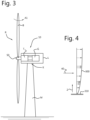
- Figure 4 an illustration of a standard wind shear profile is shown.
- the blockage effect occurs when the wind turbine farm forms an obstacle to the wind field and causes the deflection of the wind over and around the wind turbine farm area. This effect is observable by measuring the vertical wind shear profile (or its characteristics) above at least the wind turbine farm area.
- the invention provides a method for measurement or prediction of the vertical wind shear profile upwind from and/or above the wind turbine farm area.
- Figure 1 schematically shows a wind turbine farm 100 comprising a plurality of wind turbines 10 in accordance with an embodiment of the invention.
- a wind turbine farm 100 typically comprises a plurality of wind turbines 10 that are arranged within a wind turbine farm area 50.
- the wind turbines are located in the wind turbine farm area can be spaced apart at predetermined intervals, for example in a rectangular grid such that any pair of neighbouring wind turbines in the farm area are spaced apart at a distance 20 of multiple times the rotor diameter D of a wind turbine.
- Other arrangements of wind turbines within the wind turbine farm are also possible, including also an irregular arrangement of wind turbines within the wind turbine farm area.
- the wind turbine farm 100 is equipped with means for measuring a vertical wind shear profile at the location of the wind turbine farm.
- the wind turbine farm is provided with a light detection and ranging, LIDAR, system 30 which is arranged, within or nearby the wind turbine farm, to probe a wind field component in vertical direction of a wind field 40 above the wind turbine farm for measurement or prediction of the vertical wind shear profile.
- LIDAR light detection and ranging
- the LIDAR system 30 can be located within the wind turbine farm area 50, such that a view of the wind field 40 above the area is obtained.
- the LIDAR system 30 can be either ground based or be positioned at a level equal to or comparable with the top of the wind turbine 10 (e.g., the average level of the nacelle of the wind turbines).
- the measurement of the vertical wind shear profile or wind shear measurement to predict the vertical wind shear profile is performed within the wind turbine farm area 50 or nearby.
- the method involves that measurements are performed up to about 20 km from the wind turbine farm 100 in upwind direction and upto a height of about 20 rotor diameters D above the wind turbine farm.
- the method comprises that the measurement or prediction of the vertical wind shear profile is carried out by probing the wind field 40 in vertical direction above the wind turbine farm for measurement or prediction of the vertical wind shear profile.
- measuring or predicting the vertical wind shear profile is to be construed as deriving the vertical wind shear profile from characteristics measured on the wind field above the wind turbine farm in vertical direction.
- the LIDAR system 30 can be arranged additionally to probe the wind field 40 in front (i.e., the upwind direction) of and/or around the wind turbine farm area 50 to determine the blockage effect and/or the wind shear effect.
- the LIDAR system is configured as a scanning LIDAR system, which allows to measure over a relatively larger area above and/or around the wind turbine farm area.
- the method may comprise the measurement or prediction of the vertical wind shear profile by means of wind measurements by a RADAR (radio detection and ranging) based system 35 within or nearby the wind turbine farm area.
- RADAR radio detection and ranging
- the method for measuring or predicting a vertical wind shear profile located above a level of the rotors of the wind turbines 10 comprises additional control steps: a step of determining an adjustment of operational parameters for each of the wind turbines based on a value of the measured or predicted vertical wind shear profile such that a yield of electric power of the wind turbine farm is optimized with respect to the measured or predicted vertical wind shear profile, and a step of adapting the operational parameters of the one or more wind turbines according to the adjustment.
- the method comprises that the adjustment is determined as a function of a wind direction across the wind turbine farm.
- the method comprises a step for controlling the wind turbine farm to adjust at least a setting of an axial induction of individual wind turbines based on the measured or predicted vertical wind shear profile to counteract the non-standard wind shear profile or the 'blockage' effect.
- the method may comprise determining the adjustment for a setting of the axial induction, and adapting the setting of the axial induction of the one or more wind turbines according to the adjustment. This will be described in more detail below.
- the wind turbines 10 are each adjustable by means of one or more operational parameters in order to achieve an optimal efficiency under certain arbitrary operational conditions.
- the operational parameters of a wind turbine are related to settings for the various parts of the wind turbine, comprising the rotor assembly, the rotor blades, the yawing system and the generator system settings.
- the method comprises that the operational parameters are adapted by pitching the rotor blades and/or adjusting of a rotor speed.
- the method comprises that the operational parameters are adapted by individual pitch control of each of the rotor blades for adjusting the axial induction over the plane of the rotor.
- the method may comprise determining the adjustment for a setting of the yaw angle, and adapting the setting of the yaw angle of the one or more wind turbines according to the adjustment.
- Figure 2 schematically shows a controller arrangement 200 for controlling operational parameters of one or more wind turbines according to an embodiment of the invention.
- the controller arrangement comprises an input 202, an output 204, a processing unit 206, in which the input is connected to the processing unit for providing the input signal, the processing unit 206 which comprises at least one processor 207 coupled to a memory 208, is connected to the output 204.
- the output is arranged with connections with a wind turbine farm controller or to individual wind turbine controllers 210.
- the controller arrangement 200 is set up to receive at the input an input signal that relates to the measured or predicted wind shear profile 220 obtained from a wind shear profile providing service or from a measurement system 230 that measures a vertical wind speed profile, and is configured to adjust the operational parameters of one or more wind turbines in order to optimize the energy capture from the wind turbine farm in accordance with the measured or predicted wind shear profile.
- the adjustment of the operational parameters may involve that the blockage effect is reduced by creating a larger wind flow through the wind farm.
- the input may be arranged to receive some operational data 240 from the wind turbine farm for use in the optimization process.
- the controller arrangement comprises communication facilities that provide functionality for communication with local controllers 210 of individual wind turbines and may be local (“on-site”) or remote (“off-site”) relative to the wind turbine farm area 50.
- the wind profile 300 denotes the average wind speed as a function of height z above ground level 310.
- V(z) is the wind speed at height z
- V T the wind speed at the height of the turbine
- z T is the height of the turbine
- ⁇ is the exponent.
- a measured vertical wind speed profile can be compared with the model to detect any indication of blockage or wind shear. If such indication is observed, the energy capture by wind turbines 10, in particular positioned in the upstream direction in the wind turbine farm 100, can be adjusted (i.e., reduced) to obtain a higher wind speed in the downstream region of the wind turbine farm.
- the blockage can be reduced. Reducing blockage allows more energy to enter the boundaries of the wind turbine farm. Adjusting to the wind shear allows the wind farm to adjust (within limits) the energy recovery from wind flowing over the wind turbine farm area 50.
- the measured or predicted vertical wind shear profile is thus communicated to controller arrangement 200 coupled to the wind turbine farm controller 210 or the controller 210 of individual wind turbines in the wind turbine farm area 50 to adjust the operational parameters thereof in a manner that the energy capture from the wind field 40 by the wind turbine farm 100 as a whole is enhanced by taking into account the actual vertical wind shear profile and optionally also the actual blockage effect.
- controller arrangement 200 may include other control functions for the wind turbine farm or individual wind turbines that will be known the skilled in the art and therefore will not be described here.
- the input 202 ports of the controller arrangement 200 are configured to receive signals from the measurement or prediction system that represent at least parameters indicative of the vertical wind shear profile. Additionally, the signals may correspond with parameters indicative of the blockage effect and/or the wind field in upwind direction and/or around the wind turbine farm area.
- the output ports 204 are arranged for connection to the controller 210 of the wind turbine farm or the operational control of each individual wind turbine 10 and for transmitting data to the respective controller for control of the operational parameters of the respective wind turbine.
- the processor 207 is configured by means of an algorithm to carry out a controller function. First the processor is arranged to receive the signals from the input ports 202. Based on the received signals the processor is arranged to determine the parameters relating to the vertical wind shear profile and optionally the blockage effect. Based on the parameters relating to at least the vertical wind shear profile the processor is further configured to determine adjustments of the operational parameters of individual wind turbines 10 for improving the overall energy capture of the wind turbine farm 100. Finally, the processor communicates the adjustments to the controller 210 of each individual wind turbine by transmission of adjustment signals over the output ports. In an embodiment, the controller arrangement is also capable of adjusting a yaw angle of individual wind turbines 10 to overall energy capture of the wind turbine farm in relation to the wind shear profile and/or 'blockage' effect.
- the algorithm to be executed on the at least one processor is embodied in instructions for the processor to carry out in order to perform the controller function.
- the instructions may be provided on a data storage medium for downloading to the memory 208 coupled to the at least one processor 207.
- controller arrangement 200 may be arranged for connecting to output devices such as a display, input devices such as a keyboard, network communication devices, external storage devices, etc., as known in the art.
- controller arrangement may be configured to adapt an axial induction of one or more wind turbines 10 in the wind turbine farm 100 by adjusting their operational parameters as explained above.
- the axial induction (indicated a) of the wind turbine is defined as the fractional reduction of the wind shear at the rotor of the wind turbine by the rotor extracting energy, perpendicular to the rotor.
- the axial induction a is equal to 1/3.
- an axial force is defined as the force in the rotor shaft direction exerted by the wind on the turbine.
- FIG 3 shows a schematic view of a wind turbine 10 according to an embodiment of the invention.
- Wind turbine 10 comprises a rotor R with a rotor shaft S0 provided with a number of rotor blades B.
- the rotor R having a rotor diameter D is coupled to a transmission T for attaching the rotor shaft to a generator system comprising an electric generator G by means of the rotor shaft.
- the electric generator G is provided with an output for the output of electrical energy, for example through a power converter (not shown) to an electricity network.
- the assembly of rotor R, transmission T and electric generator G is located in a nacelle L on a tower M.
- the assembly of rotor R, transmission T and electric generator G is pivotally connected to the tower M by means of a yaw bearing K that constitutes part of a yaw system. It will be understood that the transmission T may be excluded when the rotor shaft is coupled directly to the generator, i.e. in the case of a low-speed generator.
- the operational parameters that can be controlled by the controller arrangement are related to the parts R, B, Y, K, G shown and mentioned here in figure 3 .
- Pitch angles, rotor speed and yaw angles define the behaviour in the rotor plane for a horizontal axis wind turbine
- pitch angles may be time-varying and azimuth dependent.
- the pitch angle and generator torque can be varied.
- the transmission ratio may be varied.
- the operational parameters may involve a setting of the axial induction of one or more wind turbines. Accordingly, an adjustment for the setting of the axial induction is determined, and the setting of the axial induction of the one or more wind turbines is adapted according to the adjustment.
- the operational parameters may involve control of the rotor R and/or rotor blades B, where the operational parameters are adapted by pitching A1 the rotor blades B and/or adjusting of a rotor speed according to the determined adjustment.
- the operational parameters are adapted by individual pitch control of each of the rotor blades for adjusting the axial induction over the plane of the rotor.
- the operational parameters may involve control of the yaw system by means of the yaw angle K in which the method comprises determining the adjustment for a setting of the yaw angle from the measured or predicted vertical wind shear profile, and adapting the setting of the yaw angle of the one or more wind turbines according to the adjustment.
- the wind turbine 10 is coupled to a remote generator system (not shown) which comprises an electric generator driven by pressurized fluid from a hydraulic pressurized fluid line.
- a remote generator system (not shown) which comprises an electric generator driven by pressurized fluid from a hydraulic pressurized fluid line.
- the rotor of the wind turbine is coupled to a torque pump which in use produces pressurized fluid to energize an hydraulic drive coupled to the electric generator.
- Figure 4 schematically shows an example of a standard wind shear profile 300 for undisturbed wind in which the wind shear varies according to a power law as a function of height z relative to the ground level 310 of the wind turbine farm. Accordingly, at ground level the wind shear is minimal and approaches a maximum constant speed at higher altitude. As described above, in practice the shape of the vertical wind shear profile may differ from the this ideal shape in various manners.
Landscapes
- Engineering & Computer Science (AREA)
- Life Sciences & Earth Sciences (AREA)
- Sustainable Development (AREA)
- Sustainable Energy (AREA)
- Chemical & Material Sciences (AREA)
- Combustion & Propulsion (AREA)
- Mechanical Engineering (AREA)
- General Engineering & Computer Science (AREA)
- Power Engineering (AREA)
- Physics & Mathematics (AREA)
- Fluid Mechanics (AREA)
- Wind Motors (AREA)
Claims (15)
- Verfahren zum Betreiben einer Windturbinenanlage mit einer Vielzahl von Windturbinen, die zusammen in einem Windturbinenanlagenbereich angeordnet sind; wobei jede Windturbine einen Turm, ein Generatorsystem zum Erzeugen von elektrischer Energie und einen Rotor umfasst, der mit einer Anzahl von Rotorblättern auf einer Rotorachse versehen ist, die mit dem elektrischen Generator zum Antreiben des Generators gekoppelt ist, wobei der Rotor auf dem Turm angeordnet ist;
wobei das Verfahren Folgendes umfasst:- Bereitstellen einer Windturbinenanlagensteuerung zum Steuern von Betriebsparametern für jede der Windturbinen;- Bereitstellen einer Messung oder einer Vorhersage eines senkrechten Windscherungsprofils, das sich über dem Niveau der Rotoren der Windturbinen befindet;- basierend auf einem Wert des gemessenen oder vorhergesagten senkrechten Windscherungsprofils, Bestimmen einer Anpassung eines oder mehrerer Betriebsparameter für jede der Windturbinen, so dass eine Ausbeute an elektrischer Energie der Windturbinenanlage in Bezug auf das gemessene oder vorhergesagte senkrechte Windscherungsprofil optimiert wird, und Anpassen der Betriebsparameter der einen oder mehreren Windturbinen gemäß der Anpassung. - Verfahren nach Anspruch 1, wobei die Betriebsparameter eines oder mehreres aus einer Gruppe umfasst, die Folgendes umfasst: axiale Induktion, Rotorgeschwindigkeit, Rotorblattwinkel, Gierwinkel und Getriebeeinstellungen jeder der Windturbinen.
- Verfahren nach einem der vorhergehenden Ansprüche 1 - 2, wobei das Verfahren ferner das Bereitstellen einer Messung oder einer Vorhersage eines Blockierungseffekts einer Windturbinenanlage auf einer dem Wind zugewandten Seite der Windturbinenanlage und/oder an einem oder mehreren Standorten rund um den Windturbinenanlagenbereich umfasst.
- Verfahren nach Anspruch 3, wobei das gemessene oder vorhergesagte senkrechte Windscherungsprofil mit dem gemessenen oder vorhergesagten Blockierungseffekt der Windturbinenanlage kombiniert wird.
- Verfahren nach einem der vorhergehenden Ansprüche 1 - 4, wobei die Messung des senkrechten Windscherungsprofils mittels Lichterfassungs- und Ranging (LIDAR)-Messung ausgeführt wird.
- Verfahren nach Anspruch 5, wobei die LIDAR-Messung eine scannende LIDAR-Messung ist.
- Verfahren nach Anspruch 5 oder 6, wobei sich eine oder mehrere LIDAR-Messvorrichtungen innerhalb des Windturbinenanlagenbereichs, optional über dem Niveau der Rotoren befinden.
- Steuerungsanordnung zum Steuern von Betriebsparametern einer Windturbinenanlage, die eine Vielzahl von Windturbinen umfasst, die zusammen in einem Windturbinenanlagenbereich angeordnet sind; wobei jede Windturbine einen Turm, ein Generatorsystem zum Erzeugen von elektrischer Energie und einen Rotor umfasst, der mit einer Anzahl von Rotorblättern auf einer Rotorachse versehen ist, die mit dem elektrischen Generator zum Antreiben des Generators gekoppelt ist, wobei der Rotor und der elektrische Generator auf dem Turm angeordnet sind, wobei die Steuerungsanordnung mit Betriebssteuerungen jeder der Windturbinen gekoppelt ist und mindestens einen Prozessor umfasst, wobei der Prozessor zu Folgendem konfiguriert ist:- Empfangen einer Messung oder einer Vorhersage eines senkrechten Windscherungsprofils, das sich über einem Niveau der Rotoren der Windturbinen befindet;- basierend auf einem Wert des gemessenen oder vorhergesagten senkrechten Windscherungsprofils, Bestimmen einer Anpassung der Betriebsparameter für jede der Windturbinen, so dass eine Ausbeute an elektrischer Energie der Windturbinenanlage in Bezug auf das gemessene oder vorhergesagte senkrechte Windscherungsprofil optimiert wird, und- nach dem Übertragen der Betriebsparameter an die betreffenden Betriebssteuerungen, Anpassen der Betriebsparameter einer oder mehrerer der Windturbinen gemäß der Anpassung.
- Steuerungsanordnung nach Anspruch 8, wobei die Betriebsparameter eines oder mehreres aus einer Gruppe umfassen, die axiale Induktion und Gierwinkel umfasst.
- Steuerungsanordnung nach Anspruch 8 oder 9, wobei die Messung des senkrechten Windscherungsprofils von mindestens einer Lichterfassungs- und Ranging (LIDAR)-Messvorrichtung empfangen wird.
- Steuerungsanordnung nach Anspruch 8 oder 9, wobei die Vorhersage des senkrechten Windscherungsprofils aus meteorologischen Messungen und/oder aus indirekten Messungen, wie z.B. einer Meeresrauheit, Umgebungstemperatur usw. oder Windscherungsmessungen außerhalb des Windanlagenbereichs abgeleitet oder geschätzt wird.
- Steuerungsanordnung nach Anspruch 10, wobei sich die mindestens eine LIDAR-Messvorrichtung innerhalb einer Distanz von ca. 40 km oder weniger von dem Windturbinenanlagenbereich befindet.
- Windturbinenanlage mit einer Vielzahl von Windturbinen, die zusammen in einem Windturbinenanlagenbereich angeordnet sind; wobei jede Windturbine einen Turm, ein Generatorsystem zum Erzeugen von elektrischer Energie und einen Rotor umfasst, der mit einer Anzahl von Rotorblättern auf einer Rotorachse versehen ist, die mit dem Generatorsystem zum Antreiben des Generatorsystems gekoppelt ist, wobei der Rotor auf dem Turm angeordnet ist, wobei die Windturbinenanlage mit einer Steuerungsanordnung gemäß einem der Ansprüche 8 - 12 versehen ist oder die Windturbinenanlage durch ein Verfahren gemäß einem der Ansprüche 1 - 7 betrieben wird.
- Steuerungs-Software, die Anweisungen zur Ausführung einer Steuerungsanordnung einer Windturbinenanlage durch mindestens einen Prozessor umfasst, wobei die Anweisungen nach dem Laden dem Prozessor Folgendes ermöglichen:- Empfangen einer Messung oder einer Vorhersage eines senkrechten Windscherungsprofils, das sich über einem Niveau der Rotoren der Windturbinen befindet;- basierend auf einem Wert des gemessenen oder vorhergesagten senkrechten Windscherungsprofils, Bestimmen einer Anpassung eines oder mehrerer Betriebsparameter für jede der Windturbinen, so dass eine Ausbeute an elektrischer Energie der Windturbinenanlage in Bezug auf das gemessene oder vorhergesagte senkrechte Windscherungsprofil optimiert wird, und- Anpassen der Betriebsparameter der einen oder mehreren Windturbinen gemäß der Anpassung.
- Datenspeichervorrichtung, die Steuerungs-Software nach Anspruch 14 enthält.
Applications Claiming Priority (2)
| Application Number | Priority Date | Filing Date | Title |
|---|---|---|---|
| EP20194389.1A EP3964708A1 (de) | 2020-09-03 | 2020-09-03 | Verfahren und steuerungsanordnung zum betreiben einer windturbinenanlage |
| PCT/EP2021/074377 WO2022049251A1 (en) | 2020-09-03 | 2021-09-03 | Method and controller arrangement for operating a wind turbine farm |
Publications (3)
| Publication Number | Publication Date |
|---|---|
| EP4208641A1 EP4208641A1 (de) | 2023-07-12 |
| EP4208641B1 true EP4208641B1 (de) | 2024-11-06 |
| EP4208641C0 EP4208641C0 (de) | 2024-11-06 |
Family
ID=72355922
Family Applications (2)
| Application Number | Title | Priority Date | Filing Date |
|---|---|---|---|
| EP20194389.1A Withdrawn EP3964708A1 (de) | 2020-09-03 | 2020-09-03 | Verfahren und steuerungsanordnung zum betreiben einer windturbinenanlage |
| EP21773503.4A Active EP4208641B1 (de) | 2020-09-03 | 2021-09-03 | Verfahren und steuerungsanordnung zum betreiben einer windturbinenanlage |
Family Applications Before (1)
| Application Number | Title | Priority Date | Filing Date |
|---|---|---|---|
| EP20194389.1A Withdrawn EP3964708A1 (de) | 2020-09-03 | 2020-09-03 | Verfahren und steuerungsanordnung zum betreiben einer windturbinenanlage |
Country Status (3)
| Country | Link |
|---|---|
| US (1) | US20230323857A1 (de) |
| EP (2) | EP3964708A1 (de) |
| WO (1) | WO2022049251A1 (de) |
Families Citing this family (2)
| Publication number | Priority date | Publication date | Assignee | Title |
|---|---|---|---|---|
| CN114856908A (zh) * | 2022-05-06 | 2022-08-05 | 北京华能新锐控制技术有限公司 | 一种基于激光雷达扫描风机叶片的风电场控制器设计方法 |
| NL2035763B1 (en) * | 2023-09-07 | 2025-03-13 | Univ Delft Tech | Wind turbine cluster control for improved cluster wake mixing |
Family Cites Families (5)
| Publication number | Priority date | Publication date | Assignee | Title |
|---|---|---|---|---|
| NL1021078C1 (nl) * | 2002-07-15 | 2004-01-16 | Energieonderzoek Ct Petten Ecn | Werkwijze en inrichting betreffende stromingsenergie zoals een windturbinepark. |
| GB0316241D0 (en) * | 2003-07-11 | 2003-08-13 | Qinetiq Ltd | Wind speed measurement apparatus and method |
| WO2013037374A1 (en) * | 2011-09-13 | 2013-03-21 | Vestas Wind Systems A/S | A method for improving large array wind park power performance through active wake manipulation reducing shadow effects |
| GB2534578A (en) * | 2015-01-28 | 2016-08-03 | Marine Current Turbines Ltd | Turbine control method |
| US10605228B2 (en) * | 2018-08-20 | 2020-03-31 | General Electric Company | Method for controlling operation of a wind turbine |
-
2020
- 2020-09-03 EP EP20194389.1A patent/EP3964708A1/de not_active Withdrawn
-
2021
- 2021-09-03 US US18/043,066 patent/US20230323857A1/en active Pending
- 2021-09-03 EP EP21773503.4A patent/EP4208641B1/de active Active
- 2021-09-03 WO PCT/EP2021/074377 patent/WO2022049251A1/en not_active Ceased
Also Published As
| Publication number | Publication date |
|---|---|
| US20230323857A1 (en) | 2023-10-12 |
| EP3964708A1 (de) | 2022-03-09 |
| WO2022049251A1 (en) | 2022-03-10 |
| EP4208641A1 (de) | 2023-07-12 |
| EP4208641C0 (de) | 2024-11-06 |
Similar Documents
| Publication | Publication Date | Title |
|---|---|---|
| CN109219782B (zh) | 用于控制动态系统的系统及方法 | |
| JP5318454B2 (ja) | 風力タービンの運転方法及び風力タービン | |
| JP6001770B2 (ja) | 風力発電装置、および風力発電装置またはウィンドパークの制御方法 | |
| US9606518B2 (en) | Control system and method of predicting wind turbine power generation | |
| EP2762721B1 (de) | Verfahren und Vorrichtung für eine Windturbinen-Rauschverminderung | |
| EP3317523B1 (de) | Verfahren und systeme zur erzeugung von windturbinensteuerungsplänen | |
| EP3317525B1 (de) | Verfahren und systeme zur erzeugung von windturbinensteuerungsplänen | |
| CN111801493A (zh) | 确定用于风力涡轮机的控制设置 | |
| EP2719895B1 (de) | Verfahren zur Überwachung einer Windturbine | |
| EP3317524B1 (de) | Verfahren und systeme zur erzeugung von windturbinensteuerungsplänen | |
| EP4027009B1 (de) | Schubregelung für windturbinen mit aktiver erfassung von windturbulenzen | |
| EP4208641B1 (de) | Verfahren und steuerungsanordnung zum betreiben einer windturbinenanlage | |
| EP3737857B1 (de) | Verfahren zur steuerung eines windparks unter berücksichtigung von nachlaufeffekten | |
| US6993965B2 (en) | Horizontal axis wind turbine and method for measuring upflow angle | |
| US9903340B2 (en) | System and method of controlling a wind turbine | |
| US20240337250A1 (en) | Method for controlling a wind farm by means of an optimization method | |
| Chanprasert et al. | Large Eddy Simulation of wind turbine wake interaction in directionally sheared inflows | |
| US20240229766A9 (en) | Method for operating a wind turbine | |
| Krishna et al. | BEM prediction of wind turbine operation and performance | |
| CN120042751A (zh) | 用于确定尾流行为的方法和控制器 | |
| Wagner | 5 Power performance measurement | |
| Hu et al. | Effective wind speed estimation and optimized setting strategy for WTGS based on SCADA system | |
| Robinson et al. | 30Wind energy | |
| DK201570195A1 (en) | Control system for wind turbine having multiple rotors |
Legal Events
| Date | Code | Title | Description |
|---|---|---|---|
| STAA | Information on the status of an ep patent application or granted ep patent |
Free format text: STATUS: UNKNOWN |
|
| STAA | Information on the status of an ep patent application or granted ep patent |
Free format text: STATUS: THE INTERNATIONAL PUBLICATION HAS BEEN MADE |
|
| PUAI | Public reference made under article 153(3) epc to a published international application that has entered the european phase |
Free format text: ORIGINAL CODE: 0009012 |
|
| STAA | Information on the status of an ep patent application or granted ep patent |
Free format text: STATUS: REQUEST FOR EXAMINATION WAS MADE |
|
| 17P | Request for examination filed |
Effective date: 20230314 |
|
| AK | Designated contracting states |
Kind code of ref document: A1 Designated state(s): AL AT BE BG CH CY CZ DE DK EE ES FI FR GB GR HR HU IE IS IT LI LT LU LV MC MK MT NL NO PL PT RO RS SE SI SK SM TR |
|
| DAV | Request for validation of the european patent (deleted) | ||
| DAX | Request for extension of the european patent (deleted) | ||
| GRAP | Despatch of communication of intention to grant a patent |
Free format text: ORIGINAL CODE: EPIDOSNIGR1 |
|
| STAA | Information on the status of an ep patent application or granted ep patent |
Free format text: STATUS: GRANT OF PATENT IS INTENDED |
|
| INTG | Intention to grant announced |
Effective date: 20240328 |
|
| GRAS | Grant fee paid |
Free format text: ORIGINAL CODE: EPIDOSNIGR3 |
|
| GRAA | (expected) grant |
Free format text: ORIGINAL CODE: 0009210 |
|
| STAA | Information on the status of an ep patent application or granted ep patent |
Free format text: STATUS: THE PATENT HAS BEEN GRANTED |
|
| AK | Designated contracting states |
Kind code of ref document: B1 Designated state(s): AL AT BE BG CH CY CZ DE DK EE ES FI FR GB GR HR HU IE IS IT LI LT LU LV MC MK MT NL NO PL PT RO RS SE SI SK SM TR |
|
| REG | Reference to a national code |
Ref country code: GB Ref legal event code: FG4D |
|
| REG | Reference to a national code |
Ref country code: CH Ref legal event code: EP |
|
| REG | Reference to a national code |
Ref country code: DE Ref legal event code: R096 Ref document number: 602021021486 Country of ref document: DE |
|
| REG | Reference to a national code |
Ref country code: IE Ref legal event code: FG4D |
|
| U01 | Request for unitary effect filed |
Effective date: 20241204 |
|
| U07 | Unitary effect registered |
Designated state(s): AT BE BG DE DK EE FI FR IT LT LU LV MT NL PT RO SE SI Effective date: 20241212 |
|
| PG25 | Lapsed in a contracting state [announced via postgrant information from national office to epo] |
Ref country code: HR Free format text: LAPSE BECAUSE OF FAILURE TO SUBMIT A TRANSLATION OF THE DESCRIPTION OR TO PAY THE FEE WITHIN THE PRESCRIBED TIME-LIMIT Effective date: 20241106 Ref country code: IS Free format text: LAPSE BECAUSE OF FAILURE TO SUBMIT A TRANSLATION OF THE DESCRIPTION OR TO PAY THE FEE WITHIN THE PRESCRIBED TIME-LIMIT Effective date: 20250306 |
|
| PG25 | Lapsed in a contracting state [announced via postgrant information from national office to epo] |
Ref country code: ES Free format text: LAPSE BECAUSE OF FAILURE TO SUBMIT A TRANSLATION OF THE DESCRIPTION OR TO PAY THE FEE WITHIN THE PRESCRIBED TIME-LIMIT Effective date: 20241106 |
|
| PG25 | Lapsed in a contracting state [announced via postgrant information from national office to epo] |
Ref country code: NO Free format text: LAPSE BECAUSE OF FAILURE TO SUBMIT A TRANSLATION OF THE DESCRIPTION OR TO PAY THE FEE WITHIN THE PRESCRIBED TIME-LIMIT Effective date: 20250206 |
|
| PG25 | Lapsed in a contracting state [announced via postgrant information from national office to epo] |
Ref country code: GR Free format text: LAPSE BECAUSE OF FAILURE TO SUBMIT A TRANSLATION OF THE DESCRIPTION OR TO PAY THE FEE WITHIN THE PRESCRIBED TIME-LIMIT Effective date: 20250207 |
|
| PG25 | Lapsed in a contracting state [announced via postgrant information from national office to epo] |
Ref country code: PL Free format text: LAPSE BECAUSE OF FAILURE TO SUBMIT A TRANSLATION OF THE DESCRIPTION OR TO PAY THE FEE WITHIN THE PRESCRIBED TIME-LIMIT Effective date: 20241106 |
|
| PG25 | Lapsed in a contracting state [announced via postgrant information from national office to epo] |
Ref country code: RS Free format text: LAPSE BECAUSE OF FAILURE TO SUBMIT A TRANSLATION OF THE DESCRIPTION OR TO PAY THE FEE WITHIN THE PRESCRIBED TIME-LIMIT Effective date: 20250206 |
|
| PG25 | Lapsed in a contracting state [announced via postgrant information from national office to epo] |
Ref country code: SM Free format text: LAPSE BECAUSE OF FAILURE TO SUBMIT A TRANSLATION OF THE DESCRIPTION OR TO PAY THE FEE WITHIN THE PRESCRIBED TIME-LIMIT Effective date: 20241106 |
|
| PG25 | Lapsed in a contracting state [announced via postgrant information from national office to epo] |
Ref country code: SK Free format text: LAPSE BECAUSE OF FAILURE TO SUBMIT A TRANSLATION OF THE DESCRIPTION OR TO PAY THE FEE WITHIN THE PRESCRIBED TIME-LIMIT Effective date: 20241106 |
|
| PG25 | Lapsed in a contracting state [announced via postgrant information from national office to epo] |
Ref country code: CZ Free format text: LAPSE BECAUSE OF FAILURE TO SUBMIT A TRANSLATION OF THE DESCRIPTION OR TO PAY THE FEE WITHIN THE PRESCRIBED TIME-LIMIT Effective date: 20241106 |
|
| PLBE | No opposition filed within time limit |
Free format text: ORIGINAL CODE: 0009261 |
|
| STAA | Information on the status of an ep patent application or granted ep patent |
Free format text: STATUS: NO OPPOSITION FILED WITHIN TIME LIMIT |
|
| 26N | No opposition filed |
Effective date: 20250807 |
|
| PGFP | Annual fee paid to national office [announced via postgrant information from national office to epo] |
Ref country code: GB Payment date: 20250919 Year of fee payment: 5 |
|
| U20 | Renewal fee for the european patent with unitary effect paid |
Year of fee payment: 5 Effective date: 20250924 |