EP4208349B1 - Sicherheitsdokumente oder -artikel mit optischen effektschichten mit magnetischen oder magnetisierbaren pigmentpartikeln und verfahren zur herstellung der besagten optischen effektschichten - Google Patents
Sicherheitsdokumente oder -artikel mit optischen effektschichten mit magnetischen oder magnetisierbaren pigmentpartikeln und verfahren zur herstellung der besagten optischen effektschichten Download PDFInfo
- Publication number
- EP4208349B1 EP4208349B1 EP21769960.2A EP21769960A EP4208349B1 EP 4208349 B1 EP4208349 B1 EP 4208349B1 EP 21769960 A EP21769960 A EP 21769960A EP 4208349 B1 EP4208349 B1 EP 4208349B1
- Authority
- EP
- European Patent Office
- Prior art keywords
- platelet
- magnetic
- coating layer
- pigment particles
- magnetizable pigment
- Prior art date
- Legal status (The legal status is an assumption and is not a legal conclusion. Google has not performed a legal analysis and makes no representation as to the accuracy of the status listed.)
- Active
Links
Images


Classifications
-
- B—PERFORMING OPERATIONS; TRANSPORTING
- B42—BOOKBINDING; ALBUMS; FILES; SPECIAL PRINTED MATTER
- B42D—BOOKS; BOOK COVERS; LOOSE LEAVES; PRINTED MATTER CHARACTERISED BY IDENTIFICATION OR SECURITY FEATURES; PRINTED MATTER OF SPECIAL FORMAT OR STYLE NOT OTHERWISE PROVIDED FOR; DEVICES FOR USE THEREWITH AND NOT OTHERWISE PROVIDED FOR; MOVABLE-STRIP WRITING OR READING APPARATUS
- B42D25/00—Information-bearing cards or sheet-like structures characterised by identification or security features; Manufacture thereof
- B42D25/30—Identification or security features, e.g. for preventing forgery
- B42D25/36—Identification or security features, e.g. for preventing forgery comprising special materials
- B42D25/369—Magnetised or magnetisable materials
-
- B—PERFORMING OPERATIONS; TRANSPORTING
- B42—BOOKBINDING; ALBUMS; FILES; SPECIAL PRINTED MATTER
- B42D—BOOKS; BOOK COVERS; LOOSE LEAVES; PRINTED MATTER CHARACTERISED BY IDENTIFICATION OR SECURITY FEATURES; PRINTED MATTER OF SPECIAL FORMAT OR STYLE NOT OTHERWISE PROVIDED FOR; DEVICES FOR USE THEREWITH AND NOT OTHERWISE PROVIDED FOR; MOVABLE-STRIP WRITING OR READING APPARATUS
- B42D25/00—Information-bearing cards or sheet-like structures characterised by identification or security features; Manufacture thereof
- B42D25/30—Identification or security features, e.g. for preventing forgery
- B42D25/36—Identification or security features, e.g. for preventing forgery comprising special materials
- B42D25/378—Special inks
Definitions
- the present invention relates to the field of optical effect layers (OELs) comprising magnetically oriented magnetic or magnetizable pigment particles.
- OELs optical effect layers
- the present invention provides security documents and decorative articles comprising one or more optical effect layers (OELs) and methods for producing said OELs and the use of said OELs as anti-counterfeit means on security documents or security articles as well as decorative purposes.
- inks, compositions, coatings or layers containing oriented magnetic or magnetizable pigment particles, particularly also optically variable magnetic or magnetizable pigment particles for the production of security elements, e.g. in the field of security documents.
- Coatings or layers comprising oriented magnetic or magnetizable pigment particles are disclosed for example in US 2,570,856 ; US 3,676,273 ; US 3,791,864 ; US 5,630,877 and US 5,364,689 .
- Coatings or layers comprising oriented magnetic color-shifting pigment particles, resulting in particularly appealing optical effects, useful for the protection of security documents have been disclosed in WO 2002/090002 A2 and WO 2005/002866 A1 .
- Security features e.g. for security documents, can generally be classified into “covert” security features on the one hand, and “overt” security features on the other hand.
- the protection provided by covert security features relies on the principle that such features are difficult to detect, typically requiring specialized equipment and knowledge for detection, whereas "overt” security features rely on the concept of being easily detectable with the unaided human senses, e.g. such features may be visible and/or detectable via the tactile sense while still being difficult to produce and/or to copy.
- covert security features rely on the concept of being easily detectable with the unaided human senses, e.g. such features may be visible and/or detectable via the tactile sense while still being difficult to produce and/or to copy.
- the effectiveness of overt security features depends to a great extent on their easy recognition as a security feature.
- Magnetic or magnetizable pigment particles in printing inks or coatings allow for the production of magnetically induced images, designs and/or patterns through the application of a correspondingly structured magnetic field, inducing a local orientation of the magnetic or magnetizable pigment particles in the not yet hardened/cured (i.e. wet) coating, followed by the hardening of the coating.
- the result is a fixed and stable magnetically induced image, design or pattern.
- an optical effect layer (OEL) and to the observation direction, said OEL may display bright and dark areas.
- the optical properties of specific zones of the OEL are directly dependent on the orientation of the magnetic or magnetizable pigment particles in the coating layer forming said OEL.
- EP 2 484 455 B1 discloses OELs comprising jointly visible zones of a first and second hardened coating compositions comprising pigment particles oriented to imitate a first and a second curved surfaces.
- coating compositions comprising pigment particles oriented to imitate a curved surface produce a specular reflection zone that would be seen by an observer as a bright zone moving upon tilting the substrate carrying the coating composition (i.e. upon varying the observation direction).
- EP 2 846 932 B1 discloses OELs with platelet-shaped magnetic or magnetizable pigment particles oriented such as to display a pattern of bright and dark areas which appear to move, or to appear and disappear when the viewing angle of the optical effect layer changes.
- the particles have their maximum reflectivity (maximum projection area) in a direction perpendicular to their extended surface, and accordingly, at orthogonal view, in the image of the OEL, the bright areas correspond to particles whose orientation approximately matches that of the surface, i.e. which have a low angle ⁇ with respect to the surface of the OEL such that the incident light is substantially reflected back in the same (orthogonal) direction.
- an observer tilts said security element so as to verify its genuineness from a normal direction (i.e. an observation direction perpendicular to the substrate surface carrying the security element) to grazing angles (i.e. observation directions substantially parallel to the substrate surface), i.e. from ⁇ 90°.
- a normal direction i.e. an observation direction perpendicular to the substrate surface carrying the security element
- grazing angles i.e. observation directions substantially parallel to the substrate surface
- Prior art documents do not provide any information of the orientation and suitable elevation angles of magnetically oriented particles to produce OELs that exhibit a significative and observable variation (i.e. increase and decrease) of brightness upon conventional tilting by an observer in the process of authenticating said element.
- Document EP 1 826 731 A2 discloses a security document according to the preamble of claim 1.
- OELs optical effect layers
- methods for producing said OELs said OELs exhibiting an eye-catching and easily recognizable visual appearance by exhibiting highly contrasting highly reflective (bright) and non-reflective (dark) areas at suitable observation angles for the man in the street so at to easily authenticate of said OEL.
- a security document or a decorative object comprising a substrate (x20) having a two-dimensional surface and one or more optical effect layers (OELs) on said substrate (x20), wherein
- optical effect layers comprise mono-axially oriented platelet-shaped magnetic or magnetizable pigment particles or comprise bi-axially oriented platelet-shaped magnetic or magnetizable pigment particles
- security documents or articles described herein further comprising one or more indicia, said one or more indicia being present between the substrate (x20) and the one or more optical effect layers (OELs).
- OELs optical effect layers
- the one or more optical effect layers comprise the magnetically oriented platelet-shaped magnetic or magnetizable pigment particles in the at least partially cured coating layer (x10) and comprise magnetically oriented second platelet-shaped magnetic or magnetizable pigment particles in an at least partially cured second coating layer (x11), wherein the at least partially cured second coating layer (x11) is either at least partially or fully overlapping the at least partially cured coating layer (x10), or the at least partially cured second coating layer (x11) is adjacent to the at least partially cured coating layer (x10), or the at least partially cured second coating layer (x11) is spaced apart from the at least partially cured coating layer (x10), wherein the platelet vectors of the second platelet-shaped magnetic or magnetizable pigment particles are angled with respect to the two-dimensional surface of the substrate (x20) at the positions of the particles by an additional elevation angle y' in the at least partially cured second coating layer (x11), the
- optical effect layers OELs
- optical effect layers OELs
- OELs optical effect layers
- the step b) of exposing the coating layer (x10) described herein may be carried out so as to mono-axially orient at least a part of the platelet-shaped magnetic or magnetizable pigment particles so that the platelet vectors of neighboring platelet-shaped magnetic or magnetizable pigment particles are substantially parallel to each other.
- the step b) of exposing the coating layer (x10) described herein may be carried out so as to bi-axially orient at least a part of the platelet-shaped magnetic or magnetizable pigment particles having the main axis X described herein and a second main axis Y, the orientation being further defined by a second platelet vector which is the vector parallel to the second main axis Y of the particle, so that the platelet vectors of neighboring platelet-shaped magnetic or magnetizable pigment particles are substantially parallel to each other and the second platelet vectors of said neighboring platelet-shaped magnetic or magnetizable pigment particles are substantially parallel to each other.
- optical effect layers comprising the at least partially cured coating layer (x10) comprising the platelet-shaped magnetic or magnetizable pigment particles and an at least partially cured second coating layer (x11) comprising second platelet-shaped magnetic or magnetizable pigment particles
- said at least partially cured second coating layer (x11) may be at least partially or fully on said at least partially cured coating layer (x10) or may be at adjacent to or spaced apart from the at least partially cured coating layer (x10)
- an orientation of each of the second platelet-shaped pigment particles is defined by the platelet vector which is the vector parallel to the main axis X of the second platelet-shaped pigment particles, wherein the platelet vectors of neighboring second platelet-shaped magnetic or magnetizable pigment particles are substantially parallel to each other, and wherein the platelet vectors of the second platelet-shaped magnetic or magnetizable pigment particles are angled with respect to the two-dimensional surface of the substrate (x20) at the positions of the particles by an
- the present invention provides optical effect layers (OELs) comprising magnetically oriented magnetic or magnetizable pigment particles having specific elevation angles such as to exhibit highly contrasting highly reflective (bright) and non-reflective (dark) areas upon variation of the tilting angle by the man in the street and under diffuse illumination conditions without requiring complicated manipulations. Therefore, the OELs described herein may be easily authenticated by the man in the street.
- OELs optical effect layers
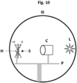
- the magnetic field lines (shown as lines with arrows pointing from the North Pole to the South Pole) of the magnetic-field generating device (x30) shown in the figures for illustration purpose have been obtained by simulation, said magnetic field simulations have been performed with the software Vizimag 3.19.
- the term "at least one" is meant to define one or more than one, for example one or two or three.
- the terms “about” and “substantially” mean that the amount or value in question may be the specific value designated or some other value in its neighborhood. Generally, the terms “about” and “substantially” denoting a certain value is intended to denote a range within ⁇ 5% of the value. As one example, the phrase “about 100” denotes a range of 100 ⁇ 5, i.e. the range from 95 to 105. Generally, when the term “about” is used, it can be expected that similar results or effects according to the invention can be obtained within a range of ⁇ 5% of the indicated value.
- substantially parallel refer to deviating not more than 2° as averaged on a coating layer surface of at least 1 mm 2 , or on at least about 100 particles from parallel alignment.
- the term “and/or” means that either all or only one of the elements of said group may be present.
- a and/or B shall mean “only A, or only B, or both A and B”.
- only A the term also covers the possibility that B is absent, i.e. "only A, but not B”.
- a coating composition comprising a compound A may include other compounds besides A.
- the term “comprising” also covers, as a particular embodiment thereof, the more restrictive meanings of "consisting essentially of” and “consisting of”, so that for instance "a mixture comprising A, B and optionally C” may also (essentially) consist of A and B, or (essentially) consist of A, B and C.
- optical effect layer denotes a coating layer that comprises oriented magnetic or magnetizable pigment particles, wherein said magnetic or magnetizable pigment particles are oriented by a magnetic field and wherein the oriented magnetic or magnetizable pigment particles are fixed/frozen in their orientation and position (i.e. after curing) so as to form a magnetically induced image.
- coating composition refers to any composition which is capable of forming an optical effect layer (OEL) on a solid substrate and which can be applied preferably but not exclusively by a printing method.
- the coating composition comprises the platelet-shaped magnetic or magnetizable pigment particles described herein and the binder described herein.
- wet refers to a coating layer which is not yet at least partially cured, for example a coating in which the platelet-shaped magnetic or magnetizable pigment particles are still able to change their positions and orientations under the influence of external forces acting upon them.
- security document refers to a document which is usually protected against counterfeit or fraud by at least one security feature.
- security documents include without limitation value documents and value commercial goods.
- security feature is used to denote an image, pattern or graphic element that can be used for authentication purposes.
- the present invention provides security documents and decorative articles comprising a substrate (x20) having a two-dimensional surface and one or more optical effect layers (OELs) on said substrate (x20), wherein said OELs are based on magnetically oriented platelet-shaped magnetic or magnetizable pigment particles, wherein the orientation of the substrate (x20) is defined by a substrate vector which is the local normal vector to the substrate (x20) perpendicular to the two-dimensional surface of the substrate (x20) at the respective position of the one or more optical effect layers (OELs).
- OELs optical effect layers
- Typical examples of decorative articles include without limitation luxury goods, cosmetic packaging, automotive parts, electronic/electrical appliances, furniture and fingernail articles.
- the one or more OELs described herein may be comprised onto an auxiliary substrate such as for example a label and consequently transferred to a decorative article in a separate step.
- Security documents include without limitation value documents and value commercial goods.
- value documents include without limitation banknotes, deeds, tickets, checks, vouchers, fiscal stamps and tax labels, agreements and the like, identity documents such as passports, identity cards, visas, driving licenses, bank cards, credit cards, transactions cards, access documents or cards, entrance tickets, public transportation tickets, academic diploma or titles and the like, preferably banknotes, identity documents, right-conferring documents, driving licenses and credit cards.
- value commercial good refers to packaging materials, in particular for cosmetic articles, nutraceutical articles, pharmaceutical articles, alcohols, tobacco articles, beverages or foodstuffs, electrical/electronic articles, fabrics or jewelry, i.e.
- the disclosed substrates, security documents and decorative articles are given exclusively for exemplifying purposes, without restricting the scope of the invention.
- the one or more OELs described herein may be comprised onto an auxiliary substrate such as for example a security thread, security stripe, a foil, a decal, a window or a label and consequently transferred to a security document in a separate step.
- the shape of the one or more OELs described herein may be continuous or discontinuous. According to one embodiment, the shape of the one or more OELs independently represent one or more indicia, dots and/or lines. For embodiments wherein the security documents and decorative articles comprise more than one, i.e. two, three, etc., OELs, said OELs may be adjacent or spaced apart.
- the eye-catching OELs described herein allows an observer to easily authenticate them upon titling between about -45° and about +45°.
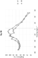
- the eye-catching visual appearance is seen as a sharp and contrasted switch-on / switch off effect of the brightness and consists off an increase of the brightness value to reach a maximum value of brightness and then a decrease of said brightness within the viewing/observation angles about -45° and about +45°, said brightness change being observable with the naked eye.
- the man in the street usually tilts about the tilting axis ⁇ the OEL with an observation angles from -45° to +45°, wherein said OEL may be tilted about i) a vertical/longitudinal axis (up/down motion) or ii) about a horizontal/latitudinal axis (left/right motion).
- said OEL may be tilted about i) a vertical/longitudinal axis (up/down motion) or ii) about a horizontal/latitudinal axis (left/right motion).
- any other kind of tilting axes ⁇ may be used.
- the eye-catching visual appearance may be seen upon tilting about i) a vertical/longitudinal axis or ii) about a horizontal/latitudinal axis.
- the eye-catching visual appearance of both of said two OELs may be seen upon tilting about i) a vertical/longitudinal axis or ii) about a horizontal/latitudinal axis; alternatively, the eye-catching visual appearance of one of said two OELs may be seen upon tilting about a vertical/longitudinal axis while, the eye-catching visual appearance of the other of said two OELs may be seen upon tilting about a horizontal/latitudinal axis.
- the platelet-shaped magnetic or magnetizable pigment particles are comprised in the radiation curable coating composition described herein as well as the coating layer (x10) as well as the at least partially cured coating layer (x10).
- the methods described herein comprise the step c) of at least partially curing the coating layer (x10) to a second state, where the platelet-shaped magnetic or magnetizable pigment particles are fixed in their current positions and orientations and can no longer move nor rotate within said layer.
- at least partially curing the coating layer (x10) it means that the platelet-shaped magnetic or magnetizable pigment particles are fixed/frozen in their adopted positions and orientations and cannot move and rotate anymore (also referred in the art as "pinning" of the particles).
- the one or more optical effect layers (OELs) described herein comprise the magnetically oriented platelet-shaped magnetic or magnetizable pigment particles in the at least partially cured coating layer.
- the platelet-shaped magnetic or magnetizable pigment particles described herein are present in an amount from about 5 wt-% to about 40 wt-%, more preferably about 10 wt-% to about 30 wt-%, the weight percentages being based on the total weight of at least partially cured coating layer.
- the platelet-shaped magnetic or magnetizable pigment particles described herein are present in an amount from about 5 wt-% to about 40 wt-%, more preferably about 10 wt-% to about 30 wt-%, the weight percentages being based on the total weight of the radiation curable coating layer described herein.
- Platelet-shaped magnetic or magnetizable pigment particles described herein are defined as having, due to their non-spherical shape, non-isotropic reflectivity with respect to an incident electromagnetic radiation for which the cured binder material is at least partially transparent.
- non-isotropic reflectivity denotes that the proportion of incident radiation from a first angle that is reflected by a particle into a certain (viewing/observation) direction (a second angle) is a function of the orientation of the particles, i.e. that a change of the orientation of the particle with respect to the first angle can lead to a different magnitude of the reflection to the viewing/observation direction.
- the platelet-shaped magnetic or magnetizable pigment particles described herein have a non-isotropic reflectivity with respect to incident electromagnetic radiation in some parts or in the complete wavelength range of from about 200 to about 2500 nm, more preferably from about 400 to about 700 nm, such that a change of the particle's orientation results in a change of reflection by that particle into a certain direction.
- the magnetic or magnetizable pigment particles described herein are different from conventional pigments, in that said conventional pigment particles exhibit the same color and reflectivity, independent of the particle orientation, whereas the magnetic or magnetizable pigment particles described herein exhibit either a reflection or a color, or both, that depend on the particle orientation.
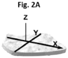
- platelet-shaped pigment particles In contrast to needle-shaped pigment particles which can be considered as one-dimensional particles, platelet-shaped pigment particles have an X-axis and a Y-axis defining a plane of predominant extension of the particles ( Fig. 2A ).
- platelet-shaped pigment particles may be considered to be two-dimensional particles due to the large aspect ratio of their dimensions, wherein the dimensions X and Y are substantially larger than dimension Z.
- Platelet-shaped pigment particles are also referred in the art as oblate particles or flakes.
- Such pigment particles may be described with a main axis X corresponding to the longest dimension crossing the pigment particle and a second main axis Y perpendicular to X which also lies within said pigment particles.
- the orientation of the platelet-shaped magnetic or magnetizable pigment particles is defined by a platelet vector which is the vector parallel to the main axis X of the particle, wherein the platelet vectors of neighboring platelet-shaped magnetic or magnetizable pigment particles are substantially parallel to each other (see Fig. 2B ), and wherein the platelet vectors of the platelet-shaped magnetic or magnetizable pigment particles are angled with respect to the two-dimensional surface of the substrate (x20) at the positions of the particles by the elevation angle ⁇ described herein.
- the elevation angle ⁇ described herein is larger than 0° and smaller than 30° (0° ⁇ ⁇ ⁇ 30°) or larger than 150° and smaller than 180° (150° ⁇ ⁇ ⁇ 180°), preferably larger than or equal to about 5° and smaller than 30° (5° ⁇ ⁇ ⁇ 30°) or larger than 150° and smaller than or equal to about 175° (150° ⁇ ⁇ ⁇ 175° ). More preferably, the elevation angle ⁇ is in the range from about 5° to about 25° (5° ⁇ ⁇ ⁇ 25°) or from about 155° to about 175° (155° ⁇ ⁇ ⁇ 175°).
- OELs comprising platelet-shaped magnetic or magnetizable pigment particles with an elevation angle of 0° are not distinguishable and could be imitated with non-magnetic pigments typically disperesed in solvent based inks, characterized upon solvent evaporation the pigments are forced to adopt elevation angle of 0°.
- the platelet-shaped magnetic or magnetizable pigment particles are oriented as described above with the elevation angle ⁇ described herein.
- the elevation angle is formed by the main axis X of the platelet-shaped magnetic or magnetizable pigment particles and the two-dimensional surface of the substrate (x20) and, wherein said elevation angle ⁇ , when measured (for example with a conoscopic scatterometer or with a microscope such as described hereafter) in a cross-section of the optical effect layer (OEL) and measured in a counterclockwise direction, is larger than 0° and smaller than 30° (0° ⁇ ⁇ ⁇ 30°) or larger than 150° and smaller than 180° (150° ⁇ ⁇ ⁇ 180°), preferably larger than or equal to about 5° and smaller than 30° (5° ⁇ ⁇ ⁇ 30°) or larger than 150° and smaller than or equal to about 175° (150° ⁇ ⁇ ⁇ 175° ). More preferably, the elevation angle ⁇ is in the
- the orientation of the platelet-shaped pigment particles is defined by the platelet vector which is the vector parallel to the main axis X of the particle, wherein the platelet vectors of neighboring platelet-shaped magnetic or magnetizable pigment particles are substantially parallel to each other; i.e. only the main axes X of neighboring platelet-shaped magnetic or magnetizable pigment particles are substantially parallel to each other (in other words, neighboring platelet-shaped magnetic or magnetizable pigment particles have a substantially same elevation angle ⁇ ).
- the orientation of the platelet-shaped pigment particles is defined by the platelet vector which is the vector parallel to the main axis X of the particle, wherein the platelet vectors of neighboring platelet-shaped magnetic or magnetizable pigment particles are substantially parallel to each other and is further defined by a second platelet vector which is the vector parallel to the second axis Y of the particle, wherein the platelet vectors of neighboring platelet-shaped magnetic or magnetizable pigment particles are substantially parallel to each other and the second platelet vectors of said neighboring platelet-shaped magnetic or magnetizable pigment particles are substantially parallel to each other.
- the platelet vectors of neighboring platelet-shaped magnetic or magnetizable pigment particles are substantially parallel to each other and not only the main axes X of neighboring platelet-shaped magnetic or magnetizable pigment particles are substantially parallel to each other (in other words, neighboring platelet-shaped magnetic or magnetizable pigment particles have a substantially same elevation angle ⁇ ) but also the main axes Y of neighboring platelet-shaped magnetic or magnetizable pigment particles are substantially parallel to each other.
- the platelet-shaped magnetic or magnetizable pigment particles are bi-axially oriented as shown for example in Fig. 2C , the platelet-shaped magnetic or magnetizable particles are substantially parallel to each other.
- Suitable examples of platelet-shaped magnetic or magnetizable pigment particles described herein include without limitation pigment particles comprising a magnetic metal selected from the group consisting of cobalt (Co), iron (Fe), and nickel (Ni); a magnetic alloy of iron, manganese, cobalt, nickel or a mixture of two or more thereof; a magnetic oxide of chromium, manganese, cobalt, iron, nickel or a mixture of two or more thereof; or a mixture of two or more thereof.
- the term "magnetic” in reference to the metals, alloys and oxides is directed to ferromagnetic or ferrimagnetic metals, alloys and oxides.
- Magnetic oxides of chromium, manganese, cobalt, iron, nickel or a mixture of two or more thereof may be pure or mixed oxides.
- magnetic oxides include without limitation iron oxides such as hematite (Fe 2 O 3 ), magnetite (Fe 3 O 4 ), chromium dioxide (CrO 2 ), magnetic ferrites (MFe 2 O 4 ), magnetic spinels (MR 2 O 4 ), magnetic hexaferrites (MFe 12 O 19 ), magnetic orthoferrites (RFeOs), magnetic garnets M 3 R 2 (AO 4 ) 3 , wherein M stands for two-valent metal, R stands for three-valent metal, and A stands for four-valent metal.
- platelet-shaped, magnetic or magnetizable pigment particles described herein include without limitation pigment particles comprising a magnetic layer M made from one or more of a magnetic metal such as cobalt (Co), iron (Fe), or nickel (Ni); and a magnetic alloy of iron, cobalt or nickel, wherein said magnetic or magnetizable pigment particles may be multilayered structures comprising one or more additional layers.
- a magnetic metal such as cobalt (Co), iron (Fe), or nickel (Ni)
- a magnetic alloy of iron, cobalt or nickel wherein said magnetic or magnetizable pigment particles may be multilayered structures comprising one or more additional layers.
- the one or more additional layers are layers A independently made from one or more selected from the group consisting of metal fluorides such as magnesium fluoride (MgF 2 ), silicon oxide (SiO), silicon dioxide (SiO 2 ), titanium oxide (TiO 2 ), and aluminum oxide (Al 2 O 3 ), more preferably silicon dioxide (SiO 2 ); or layers B independently made from one or more selected from the group consisting of metals and metal alloys, preferably selected from the group consisting of reflective metals and reflective metal alloys, and more preferably selected from the group consisting of aluminum (Al), chromium (Cr), and nickel (Ni), and still more preferably aluminum (Al); or a combination of one or more layers A such as those described hereabove and one or more layers B such as those described hereabove.
- metal fluorides such as magnesium fluoride (MgF 2 ), silicon oxide (SiO), silicon dioxide (SiO 2 ), titanium oxide (TiO 2 ), and aluminum oxide (Al 2 O 3 ),
- Typical examples of the platelet-shaped magnetic or magnetizable pigment particles being multilayered structures described hereabove include without limitation A/M multilayer structures, A/M/A multilayer structures, A/M/B multilayer structures, A/B/M/A multilayer structures, A/B/M/B multilayer structures, A/B/M/B/A/multilayer structures, B/M multilayer structures, B/M/B multilayer structures, B/A/M/A multilayer structures, B/A/M/B multilayer structures, B/A/M/B/A/multilayer structures, wherein the layers A, the magnetic layers M and the layers B are chosen from those described hereabove.
- At least a part of the preferred platelet-shaped, magnetic or magnetizable particles is constituted by platelet-shaped optically variable magnetic or magnetizable pigment particles.
- Optically variable pigments refer to pigment exhibiting a change of lightness or a combination of a change of lightness and a change of hue.
- at least a part of the platelet-shaped, magnetic or magnetizable particles is constituted by particles exhibiting a metallic color, more preferably a silver color or a gold color.
- the optical properties of the optically variable magnetic or magnetizable pigment particles may also be used as a machine readable tool for the recognition of the OEL.
- the optical properties of the optically variable magnetic or magnetizable pigment particles may simultaneously be used as a covert or semi-covert security feature in an authentication process wherein the optical (e.g. spectral) properties of the pigment particles are analyzed and thus increase the counterfeiting resistance.
- platelet-shaped, optically variable magnetic or magnetizable pigment particles in an OEL enhances the significance of said OEL as a security feature in security document applications, because such materials are reserved to the security document printing industry and are not commercially available to the public.
- the platelet-shaped, magnetic or magnetizable pigment particles are selected from the group consisting of magnetic thin-film interference pigment particles, magnetic cholesteric liquid crystal pigment particles, interference coated pigment particles comprising a magnetic material and mixtures of two or more thereof.
- Magnetic thin film interference pigment particles are known to those skilled in the art and are disclosed e.g. in US 4,838,648 ; WO 2002/073250 A2 ; EP 0 686 675 B1 ; WO 2003/000801 A2 ; US 6,838,166 ; WO 2007/131833 A1 ; EP 2 402 401 B1 ; WO 2019/103937 A1 ; WO 2020/006286 A1 and in the documents cited therein.
- the magnetic thin film interference pigment particles comprise pigment particles having a five-layer Fabry-Perot multilayer structure and/or pigment particles having a six-layer Fabry-Perot multilayer structure and/or pigment particles having a seven-layer Fabry-Perot multilayer structure and/or pigment particles having a multilayer structure combining one or more multilayer Fabry-Perot structures.
- Preferred five-layer Fabry-Perot multilayer structures consist of absorber/dielectric/reflector/dielectric/absorber multilayer structures wherein the reflector and/or the absorber is also a magnetic layer, preferably the reflector and/or the absorber is a magnetic layer comprising nickel, iron and/or cobalt, and/or a magnetic alloy comprising nickel, iron and/or cobalt and/or a magnetic oxide comprising nickel (Ni), iron (Fe) and/or cobalt (Co).
- Preferred six-layer Fabry-Perot multilayer structures consist of absorber/dielectric/reflector/magnetic/dielectric/absorber multilayer structures.
- Preferred seven-layer Fabry Perot multilayer structures consist of absorber/dielectric/reflector/magnetic/reflector/dielectric/absorber multilayer structures such as disclosed in US 4,838,648 .
- Preferred pigment particles having a multilayer structure combining one or more Fabry-Perot structures are those described in WO 2019/103937 A1 and consist of combinations of at least two Fabry-Perot structures, said two Fabry-Perot structures independently comprising a reflector layer, a dielectric layer and an absorber layer, wherein the reflector and/or the absorber layer can each independently comprise one or more magnetic materials and/or wherein a magnetic layer is sandwich between the two structures.
- WO 2020/006/286 A1 and EP 3 587 500 A1 disclose further preferred pigment particles having a multilayer structure.
- the reflector layers described herein are independently made from one or more selected from the group consisting of metals and metal alloys, preferably selected from the group consisting of reflective metals and reflective metal alloys, more preferably selected from the group consisting of aluminum (Al), silver (Ag), copper (Cu), gold (Au), platinum (Pt), tin (Sn), titanium (Ti), palladium (Pd), rhodium (Rh), niobium (Nb), chromium (Cr), nickel (Ni), and alloys thereof, even more preferably selected from the group consisting of aluminum (Al), chromium (Cr), nickel (Ni) and alloys thereof, and still more preferably aluminum (Al).
- metals and metal alloys preferably selected from the group consisting of reflective metals and reflective metal alloys, more preferably selected from the group consisting of aluminum (Al), silver (Ag), copper (Cu), gold (Au), platinum (Pt), tin (Sn), titanium (Ti), palladium
- the dielectric layers are independently made from one or more selected from the group consisting of metal fluorides such as magnesium fluoride (MgF 2 ), aluminum fluoride (AlF 3 ), cerium fluoride (CeF 3 ), lanthanum fluoride (LaF 3 ), sodium aluminum fluorides (e.g.
- metal fluorides such as magnesium fluoride (MgF 2 ), aluminum fluoride (AlF 3 ), cerium fluoride (CeF 3 ), lanthanum fluoride (LaF 3 ), sodium aluminum fluorides (e.g.
- the absorber layers are independently made from one or more selected from the group consisting of aluminum (Al), silver (Ag), copper (Cu), palladium (Pd), platinum (Pt), titanium (Ti), vanadium ( ⁇ , iron (Fe) tin (Sn), tungsten (W), molybdenum (Mo), rhodium (Rh), Niobium (Nb), chromium (Cr), nickel (Ni), metal oxides thereof, metal sulfides thereof, metal carbides thereof, and metal alloys thereof, more preferably selected from the group consisting of chromium (Cr), nickel (Ni), metal oxides thereof, and metal alloys thereof, and still more preferably selected from the group consisting of chromium (Cr), nickel (Ni), and metal alloys thereof.
- the magnetic layer comprises nickel (Ni), iron (Fe) and/or cobalt (Co); and/or a magnetic alloy comprising nickel (Ni), iron (Fe) and/or cobalt (Co); and/or a magnetic oxide comprising nickel (Ni), iron (Fe) and/or cobalt (Co).
- the magnetic thin film interference pigment particles comprise a seven-layer Fabry-Perot absorber/dielectric/reflector/magnetic/reflector/dielectric/absorber multilayer structure consisting of a Cr/MgF 2 /Al/Ni/Al/MgF 2 /Cr multilayer structure.
- the magnetic thin film interference pigment particles described herein may be multilayer pigment particles being considered as safe for human health and the environment and being based for example on five-layer Fabry-Perot multilayer structures, six-layer Fabry-Perot multilayer structures and seven-layer Fabry-Perot multilayer structures, wherein said pigment particles include one or more magnetic layers comprising a magnetic alloy having a substantially nickel-free composition including about 40 wt-% to about 90 wt-% iron, about 10 wt-% to about 50 wt-% chromium and about 0 wt-% to about 30 wt-% aluminum.
- Typical examples of multilayer pigment particles being considered as safe for human health and the environment can be found in EP 2 402 401 B1 whose content is hereby incorporated by reference in its entirety.
- Suitable magnetic cholesteric liquid crystal pigment particles exhibiting optically variable characteristics include without limitation magnetic monolayered cholesteric liquid crystal pigment particles and magnetic multilayered cholesteric liquid crystal pigment particles.
- Such pigment particles are disclosed for example in WO 2006/063926 A1 , US 6,582,781 and US 6,531,221 .
- WO 2006/063926 A1 discloses monolayers and pigment particles obtained therefrom with high brilliance and colorshifting properties with additional particular properties such as magnetizability.
- the disclosed monolayers and pigment particles, which are obtained therefrom by comminuting said monolayers, include a three-dimensionally crosslinked cholesteric liquid crystal mixture and magnetic nanoparticles.
- US 6,582,781 and US 6,410,130 disclose platelet-shaped cholesteric multilayer pigment particles which comprise the sequence A 1 /B/A 2 , wherein A 1 and A 2 may be identical or different and each comprises at least one cholesteric layer, and B is an interlayer absorbing all or some of the light transmitted by the layers A 1 and A 2 and imparting magnetic properties to said interlayer.
- US 6,531,221 discloses platelet-shaped cholesteric multilayer pigment particles which comprise the sequence A/B and optionally C, wherein A and C are absorbing layers comprising pigment particles imparting magnetic properties, and B is a cholesteric layer.
- Suitable interference coated pigment particles comprising one or more magnetic materials include without limitation structures consisting of a substrate selected from the group consisting of a core coated with one or more layers, wherein at least one of the core or the one or more layers have magnetic properties.
- suitable interference coated pigment particles comprise a core made of a magnetic material such as those described hereabove, said core being coated with one or more layers made of one or more metal oxides, or they have a structure consisting of a core made of synthetic or natural micas, layered silicates (e.g. talc, kaolin and sericite), glasses (e.g. borosilicates), silicon dioxides (SiOz), aluminum oxides (Al 2 O 3 ), titanium oxides (TiOz), graphites and mixtures of two or more thereof.
- one or more additional layers such as coloring layers may be present.
- the platelet-shaped, magnetic or magnetizable pigment particles described herein preferably have a size d50 between about 2 ⁇ m and about 50 ⁇ m (as measured by direct optical granulometry).
- the platelet-shaped magnetic or magnetizable pigment particles described herein may be surface treated so as to protect them against any deterioration that may occur in the coating composition and coating layer and/or to facilitate their incorporation in said coating composition and coating layer; typically corrosion inhibitor materials and/or wetting agents may be used.
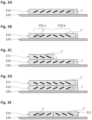
- the OELs described herein comprise a single at least partially cured coating layer (310) with magnetically oriented platelet-shaped magnetic or magnetizable pigment particles incorporated therein, wherein substantially all the platelet-shaped magnetic or magnetizable pigment particles have substantially the same elevation angle ⁇ .
- the OELs described herein comprise two zones comprising the platelet-shaped magnetic or magnetizable pigment particles, wherein substantially all the platelet-shaped magnetic or magnetizable pigment particles in the one zone have substantially the same elevation angle ⁇ and substantially all the platelet-shaped magnetic or magnetizable pigment particles in another zone have substantially the same additional elevation angle y', wherein the elevation angle ⁇ is larger than 0° and smaller than 30° (0° ⁇ ⁇ ⁇ 30°) or larger than 150° and smaller than 180° (150° ⁇ ⁇ ⁇ 180°), preferably larger than or equal to about 5° and smaller than 30° (5° ⁇ ⁇ ⁇ 30°) or larger than 150° and smaller than or equal to about 175° (150° ⁇ ⁇ ⁇ 175°), more preferably, in the range from about 5° to about 25° (5° ⁇ ⁇ ⁇ 25°) or from about 155° to about 175° (155° ⁇ ⁇ ⁇ 175
- the OELs described herein comprise a single at least partially cured coating layer (310) comprising the platelet-shaped magnetic or magnetizable pigment particles in one or more first zones (310-a) and the platelet-shaped magnetic or magnetizable pigment particles in one or more second zones (310-b), wherein substantially all the platelet-shaped magnetic or magnetizable pigment particles in the one or more first zones (310-a) have substantially the same elevation angle ⁇ and substantially all the platelet-shaped magnetic or magnetizable pigment particles in the one or more second zones (310-b) have substantially the same additional elevation angle y', wherein the elevation angle ⁇ is larger than 0° and smaller than 30° (0° ⁇ ⁇ ⁇ 30°) or larger than 150° and smaller than 180° (150° ⁇ ⁇ ⁇ 180°), preferably larger than or equal to about 5° and smaller than 30° (5° ⁇ ⁇ ⁇ 30°) or larger than 150° and smaller than or equal to about 175° (
- the OELs described herein comprise the at least partially cured coating layer (310) with magnetically oriented platelet-shaped magnetic or magnetizable pigment particles incorporated therein, wherein substantially all the platelet-shaped magnetic or magnetizable pigment particles have substantially the same elevation angle ⁇ and further comprise an at least partially cured second coating layer (311) with magnetically oriented second platelet-shaped magnetic or magnetizable pigment particles incorporated therein, wherein the platelet vectors of the second platelet-shaped magnetic or magnetizable pigment particles are angled with respect to the two-dimensional surface of the substrate (x20) at the positions of the particles by an additional elevation angle y', the additional elevation angle ⁇ ' being larger than 0° and smaller than 30° (0° ⁇ y' ⁇ 30°) or larger than 150° and smaller than 180° (150° ⁇ y' ⁇ 180°), said elevation angle ⁇ and additional elevation angle ⁇ ' being different from each other.
- the at least partially cured second coating layer (x11) is either at least partially or fully overlapping the at least partially cured coating layer (x10), or the at least partially cured second coating layer (x11) is adjacent to the at least partially cured coating layer (x10), or the at least partially cured second coating layer (x11) is spaced apart from the at least partially cured coating layer (x10).
- the OELs described herein comprise two at least partially cured coating layers (310 and 311).
- the OELs comprise i) the at least partially cured coating layer (310) with magnetically oriented platelet-shaped magnetic or magnetizable pigment particles incorporated therein as described herein and ii) an at least partially cured second coating layer (311) with magnetically oriented second platelet-shaped magnetic or magnetizable pigment particles incorporated therein, said at least partially cured second coating layer (311) partially overlapping the at least partially cured coating layer (310), wherein substantially all the platelet-shaped magnetic or magnetizable pigment particles in the at least partially cured coating layer (310) have substantially the same elevation angle ⁇ and substantially all second platelet-shaped magnetic or magnetizable pigment particles in the at least partially cured second coating layer (311) have substantially the same additional elevation angle y', wherein the elevation angle ⁇ is larger than 0° and smaller than 30° (0° ⁇ ⁇ ⁇ 30°) or larger than 150°
- the OELs described herein comprise two at least partially cured coating layers (310 and 311).
- the OELs comprise i) an at least partially cured coating layer (310) with magnetically oriented platelet-shaped magnetic or magnetizable pigment particles incorporated therein as described herein and ii) an at least partially cured second coating layer (311) with magnetically oriented second platelet-shaped magnetic or magnetizable pigment particles incorporated therein, said at least partially cured second coating layer (311) fully overlapping the at least partially cured coating layer (310), wherein substantially all the platelet-shaped magnetic or magnetizable pigment particles in the at least partially cured coating layer (310) have substantially the same elevation angle ⁇ and substantially all second platelet-shaped magnetic or magnetizable pigment particles in the at least partially cured second coating layer (311) have substantially the same elevation angle y', wherein the elevation angle ⁇ is larger than 0° and smaller than 30° (0° ⁇ ⁇ ⁇ 30°) or larger than 150° and smaller than
- elevation angle ⁇ and additional elevation angle ⁇ ' being different from each other (preferably they differ of at least 10°) and/or being not coplanar.
- the OELs described herein comprise two at least partially cured coating layers (310 and 311).
- the OELs comprise i) an at least partially cured coating layer (310) with magnetically oriented platelet-shaped magnetic or magnetizable pigment particles incorporated therein as described herein and ii) an at least partially cured second coating layer (311) with magnetically oriented second platelet-shaped magnetic or magnetizable pigment particles incorporated therein, said at least partially cured second coating layer being adjacent to ( Fig.
- the elevation angle ⁇ is larger than 0° and smaller than 30° (0° ⁇ ⁇ ⁇ 30°) or larger than 150° and smaller than 180° (150° ⁇ ⁇ ⁇ 180°), preferably larger than or equal to about 5° and smaller than 30° (5° ⁇ ⁇ ⁇ 30°) or larger than 150° and smaller than or equal to about 175° (150° ⁇ ⁇ ⁇ 175°), more preferably in the range from about 5° to about 25° (5° ⁇ ⁇ ⁇ 25°) or from about 155° to about 175° (155° ⁇ ⁇ ⁇ 175°)
- the substrate (x20) described herein is preferably selected from the group consisting of papers or other fibrous materials (including woven and non-woven fibrous materials), such as cellulose, paper-containing materials, glasses, metals, ceramics, plastics and polymers, metallized plastics or polymers, composite materials and mixtures or combinations of two or more thereof.
- Typical paper, paper-like or other fibrous materials are made from a variety of fibers including without limitation abaca, cotton, linen, wood pulp, and blends thereof. As is well known to those skilled in the art, cotton and cotton/linen blends are preferred for banknotes, while wood pulp is commonly used in non-banknote security documents.
- the substrate (x20) described herein is based on plastics and polymers, metallized plastics or polymers, composite materials and mixtures or combinations of two or more thereof.
- plastics and polymers include polyolefins such as polyethylene (PE) and polypropylene (PP) including biaxially oriented polypropylene (BOPP), polyamides, polyesters such as polyethylene terephthalate) (PET), poly(1,4-butylene terephthalate) (PBT), polyethylene 2,6-naphthoate) (PEN) and polyvinylchlorides (PVC).
- Spunbond olefin fibers such as those sold under the trademark Tyvek ® may also be used as substrate.
- Typical examples of metalized plastics or polymers include the plastic or polymer materials described hereabove having a metal disposed continuously or discontinuously on their surface.
- Typical examples of metals include without limitation aluminum (Al), chromium (Cr), copper (Cu), gold (Au), silver (Ag), alloys thereof and combinations of two or more of the aforementioned metals.
- the metallization of the plastic or polymer materials described hereabove may be done by an electrodeposition process, a high-vacuum coating process or by a sputtering process.
- Typical examples of composite materials include without limitation multilayer structures or laminates of paper and at least one plastic or polymer material such as those described hereabove as well as plastic and/or polymer fibers incorporated in a paper-like or fibrous material such as those described hereabove.
- the substrate can comprise further additives that are known to the skilled person, such as fillers, sizing agents, whiteners, processing aids, reinforcing or wet strengthening agents, etc.
- the OELs described herein are used for decorative or cosmetic purposes including for example fingernail lacquers, said OEL may be produced on other type of substrates including nails, artificial nails or other parts of an animal or human being.
- the substrates (X20) described herein may be in the form of webs, sheets, thread reels, film reels, labels of the roll or label stocks.
- the substrate may comprise printed, coated, or laser-marked or laser-perforated indicia, watermarks, security threads, fibers, planchettes, luminescent compounds, windows, foils, decals and combinations of two or more thereof.
- the substrate may comprise one or more marker substances or taggants and/or machine readable substances (e.g. luminescent substances, UV/visible/IR absorbing substances, magnetic substances and combinations thereof).
- the security documents and decorative articles comprising the substrate (x20) and the one or more OELs described herein further comprise one or more patterns, each of them independently having the shape of an indicium, wherein said one or more patterns are present between the substrate (x20) and the one or more OELs (or in other words, the one or more OELS at least partially overlap the one or more patterns).
- the term "indicium” and “indicia” shall mean continuous and discontinuous layer(s) consisting of distinguishing markings or signs or patterns.
- the indicia described herein are selected from the group consisting of codes, symbols, alphanumeric symbols, motifs, geometric patterns (e.g.
- codes include encoded marks such as an encoded alphanumeric data, a one-dimensional barcode, a two-dimensional barcode, a QR-code, datamatrix and IR-reading codes.
- the one or more indicia described herein may be solids indicia and/or raster indicia.
- the security documents and decorative articles comprising the substrate (x20) and the one or more OELs described herein further comprise one or more primer layers, wherein said one or more primer layers are present between the substrate (x20) and the one or more OELs.
- primer layers may enhance the quality of the one or more OELs described herein or promote adhesion. Examples of such primer layers may be found in WO 2010/058026 A2.
- one or more protective layers may be applied on top of the one or more OELs.
- the one or more protective layers are typically made of protective varnishes.
- Protective varnishes may be radiation curable compositions, thermal drying compositions or any combination thereof.
- the one or more protective layers are radiation curable compositions, more preferable UV-Vis curable compositions.
- the protective layers are typically applied after the formation of the OEL.
- the OELs described herein may be provided directly on the substrate (x20) on which it shall remain permanently (such as for banknote applications or labels applications). Alternatively, the OELs may also be provided on a temporary substrate for production purposes, from which the OELs are subsequently removed.
- one or more adhesive layers may be present on the one or more OELs or may be present on the substrate (x20), said one or more adhesive layers being on the side of the substrate opposite to the side where the one or more OELs are provided and/or on the same side as the one or more OELs and on top of the one or more OELs. Therefore, one or more adhesive layers may be applied to the one or more OELs or to the substrate, said one or more adhesive layers being applied after the curing step has been completed.
- Such an object may be attached to all kinds of documents or other articles or items without printing or other processes involving machinery and rather high effort.
- the substrate described herein comprising the one or more OELs described herein may be in the form of a transfer foil, which can be applied to a document or to an article in a separate transfer step.
- the substrate is provided with a release coating, on which the one or more OELs are produced.
- the present invention provides methods for producing the one or more optical effect layers (OELs) described herein on the substrates (x20) having a two-dimensional surface described herein.
- OELs optical effect layers
- the methods described herein comprise the step a) of applying on the substrate (x20) surface described herein the radiation curable coating composition comprising the platelet-shaped magnetic or magnetizable pigment particles described herein, said radiation curable coating composition being in a first, liquid state which allows its application as a coating layer (x10) and which is in a not yet at least partially cured (i.e. wet) state wherein the pigment particles can move and rotate within the layer.
- the radiation curable coating composition described herein is to be provided on the substrate (x20) surface, the radiation curable coating composition comprises at least a binder material and the magnetic or magnetizable pigment particles, wherein said composition is in a form that allows its processing on the desired printing or coating equipment.
- said step a) is carried out by a printing process, preferably selected from the group consisting of screen printing, rotogravure printing, flexography printing, intaglio printing (also referred in the art as engraved copper plate printing, engraved steel die printing), pad printing and curtain coating, more preferably selected from the group consisting of screen printing, rotogravure printing, pad printing and flexography printing and still more preferably screen printing, rotogravure printing and flexography printing.
- a printing process preferably selected from the group consisting of screen printing, rotogravure printing, flexography printing, intaglio printing (also referred in the art as engraved copper plate printing, engraved steel die printing), pad printing and curtain coating, more preferably selected from the group consisting of screen printing, rotogravure printing, pad printing and flexography printing and still more preferably screen printing, rotogravure printing and flexography printing.
- the methods described herein further comprise the step b) of exposing the coating layer (x10) to a magnetic field of a magnetic-field generating device (x30) so as to orient at least a part of the platelet-shaped magnetic or magnetizable pigment particles, wherein the platelet vectors of the platelet-shaped magnetic or magnetizable pigment particles are angled with respect to the two-dimensional surface of the substrate (x20) at the positions of the particles by the elevation angle ⁇ , said elevation angle ⁇ being larger than 0° and smaller than 30° (0° ⁇ ⁇ ⁇ 30°) or larger than 150° and smaller than 180° (150° ⁇ ⁇ ⁇ 180°), preferably larger than or equal to about 5° and smaller than 30° (5° ⁇ ⁇ ⁇ 30°) or larger than 150° and smaller than or equal to about 175° (150° ⁇ ⁇ ⁇ 175° ), more preferably, in the range from about 5° to about 25° (5° ⁇ ⁇ ⁇ 25° ) or from about 155°
- the orientation of the platelet-shaped magnetic or magnetizable pigment particles and the elevation angles ⁇ described herein are obtained by submitting the platelet-shaped magnetic or magnetizable pigment particles to the magnetic field of the magnetic-field generating device (x30) described herein in one or more areas (shown in the figures as dotted rectangles A and A') wherein the magnetic field is substantially homogeneous (i.e.
- a magnetic field which has a substantially constant magnitude and direction over the entire area(s) of interest (for mono-axial orientation); or a magnetic field which is substantially confined to a plane (for bi-axial orientation), wherein the substrate (x20) carrying the coating layer (x10) is provided in said one or more areas with an angle ⁇ formed by the coating layer (x10) and a tangent to magnetic field lines of the magnetic field of the magnetic-field generating device (x30) within the one or more areas wherein the magnetic field is substantially homogeneous.
- the angle ⁇ is larger than 0° and smaller than 30° (0° ⁇ ⁇ ⁇ 30°) or larger than 150° and smaller than 180° (150° ⁇ ⁇ ⁇ 180°), preferably larger than or equal to about 5° and smaller than 30° (5° ⁇ ⁇ ⁇ 30°) or larger than 150° and smaller than or equal to about 175° (150° ⁇ ⁇ ⁇ 175°), more preferably in the range from about 5° to about 25° (5° ⁇ ⁇ ⁇ 25°) or from about 155° to about 175° (155° ⁇ ⁇ ⁇ 175°).
- the step b) described herein is carried out to so as to mono-axially or bi-axially orient at least a part of the platelet-shaped magnetic or magnetizable pigment particles described herein.
- a bi-axial orientation means that the platelet-shaped magnetic or magnetizable pigment particles are made to orientate in such a way that their two main axes X and Y are constrained ( Fig. 2C ).
- each platelet-shaped magnetic or magnetizable pigment particle can be considered to have a major axis in the plane of the pigment particle and an orthogonal minor axis in the plane of the pigment particle.
- the axes X and Y of the platelet-shaped magnetic or magnetizable pigment particles are each caused to orient according to the magnetic field. Effectively, this results in neighboring platelet-shaped magnetic pigment particles that are close to each other in space to be substantially parallel to each other.
- a bi-axial orientation aligns the planes of the platelet-shaped magnetic or magnetizable pigment particles so that the planes of said pigment particles are oriented to be substantially parallel relative to the planes of neighboring (in all directions) platelet-shaped magnetic or magnetizable pigment particles.
- the step b) is carried out to so as to mono-axially orient at least a part of the platelet-shaped magnetic or magnetizable pigment particles described herein.
- Suitable magnetic-field generating devices for mono-axially orienting the platelet-shaped magnetic or magnetizable pigment particles described herein are not limited.
- a suitable magnetic-field generating device (430) for mono-axially orienting at least a part of the platelet-shaped magnetic or magnetizable pigment particles consists of a bar dipole magnet. As shown in Fig.
- the platelet-shaped magnetic or magnetizable pigment particles in the coating layer (410) on the substrate (420) are exposed to the magnetic field (magnetic field lines shown as lines with arrows pointing from the North Pole to the South Pole) of the magnetic field of the magnetic-field generating device (430) described herein in one or more areas (shown as a dotted rectangle A) wherein the magnetic field is substantially homogeneous and wherein the magnetic field lines are substantially parallel to each other in said one or more areas and wherein the substrate (420) carrying the coating layer (410) is provided in said one or more areas with the angle ⁇ described herein.
- the magnetic field magnetic field lines shown as lines with arrows pointing from the North Pole to the South Pole
- a suitable magnetic-field generating device (430) for mono-axially orienting at least a part of the platelet-shaped magnetic or magnetizable pigment particles consists of an assembly comprising two bar dipole magnets (M1, M2) having a same magnetic direction and an iron yoke (Y), wherein said magnetic-field generating device is described in US 7,047,883 .
- M1, M2 bar dipole magnets
- Y iron yoke
- the platelet-shaped magnetic or magnetizable pigment particles in the coating layer (410) on the substrate (420) are exposed to the magnetic field (magnetic field lines shown as lines with arrows pointing from the North Pole to the South Pole) of the magnetic field of the magnetic-field generating device (430) described herein in one or more areas (shown as a dotted rectangle A) wherein the magnetic field is substantially homogeneous and wherein the magnetic field lines are substantially parallel to each other in said one or more areas and wherein the substrate (420) carrying the coating layer (410) is provided in said one or more areas with the angle ⁇ described herein.
- the magnetic field magnetic field lines shown as lines with arrows pointing from the North Pole to the South Pole
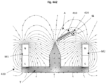
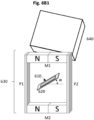
- a suitable magnetic-field generating device (630) for mono-axially orienting at least a part of the platelet-shaped magnetic or magnetizable pigment particles consists of a rectangular assembly comprising two bar dipole magnets (M1, M2) and two pole pieces (P1, P2).
- the platelet-shaped magnetic or magnetizable pigment particles in the coating layer (610) on the substrate (620) are exposed to the magnetic field (magnetic field lines shown as lines with arrows pointing from the North Pole to the South Pole) of the magnetic-field generating device (630) in one or more areas (shown as an dotted rectangle A) wherein the magnetic field is substantially homogeneous and wherein the magnetic field lines are substantially parallel to each other in said area and wherein the substrate (620) carrying the coating layer (610) is provided in said one or more areas with the angle ⁇ described herein.
- the step b) is carried out so as to bi-axially orient at least a part of the platelet-shaped magnetic or magnetizable pigment particles.
- the method described herein comprises the step of exposing the coating layer (x10) to the magnetic field of the magnetic-field generating device (x30) described herein so as to bi-axially orient at least a part of the magnetic or magnetizable pigment particle
- the coating layer (x10) may be exposed more than one time to said magnetic-field generating device.
- Suitable magnetic-field generating devices for bi-axially orienting the platelet-shaped magnetic or magnetizable pigment particles described herein are not limited.
- bi-axial orientation of platelet-shaped magnetic or magnetizable pigment particles requires a dynamic magnetic field (i.e. time-variable/time-dependent magnetic field) that changes its direction, forcing the particles to oscillate until both main axes, X-axis and Y-axis, become aligned.
- bi-axial orientation requires a non-concomitant movement of the coating layer (x10) comprising the platelet-shaped magnetic or magnetizable pigment particles with respect to the magnetic-field-generating device.
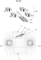
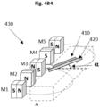
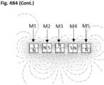
- a suitable magnetic-field generating device (430) for bi-axially orienting at least a part of the platelet-shaped magnetic or magnetizable pigment particles consists of a linear arrangement of at least four, magnets (M1-M4) that are positioned in a staggered fashion or in zigzag formation. As shown in Fig.
- the platelet-shaped magnetic or magnetizable pigment particles in the coating layer (410) on the substrate (420) are exposed to the magnetic field (magnetic field lines shown as lines with arrows pointing from the North Pole to the South Pole) of the magnetic fields of the magnetic-field generating device (430) in one or more areas (shown as dotted rectangles A, A') wherein the magnetic field is substantially homogeneous and wherein the magnetic field lines are substantially parallel to each other in said one or more areas and wherein the substrate (420) carrying the coating layer (410) is provided in said one or more areas with the angle ⁇ described herein.
- EP 2 157 141 A1 discloses a similar suitable magnetic-field generating device in Fig.
- the magnetic-field generating device may be used for bi-axially orienting at least a part of the platelet-shaped magnetic or magnetizable pigment particles and consists of a linear arrangement of at least three, preferably at least four, magnets that are positioned in a staggered fashion or in zigzag formation.
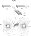
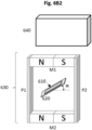
- a suitable magnetic-field generating device (430) for bi-axially orienting at least a part of the platelet-shaped magnetic or magnetizable pigment particles consists of two dipole magnets (M1, M2) having an opposite magnetic direction. As shown in Fig.
- the platelet-shaped magnetic or magnetizable pigment particles in the coating layer (410) on the substrate (420) are exposed to the magnetic field (magnetic field lines shown as lines with arrows pointing from the North Pole and the South Pole) of the magnetic fields of the magnetic-field generating device (430) in one or more areas (shown as dotted rectangles A, A') wherein the magnetic field is substantially homogeneous and wherein the magnetic field lines are substantially parallel to each other in said one or more areas and wherein the substrate (420) carrying the coating layer (410) is provided in said one or more areas with the angle ⁇ described herein.
- the magnetic field magnetic field lines shown as lines with arrows pointing from the North Pole and the South Pole
- a suitable magnetic-field generating device (430) for bi-axially orienting at least a part of the platelet-shaped magnetic or magnetizable pigment particles consists of two dipole magnets (M1, M2) having a same magnetic direction. As shown in Fig.
- the platelet-shaped magnetic or magnetizable pigment particles in the coating layer (410) on the substrate (420) are exposed to the magnetic field (magnetic field lines shown as lines with arrows pointing from the North Pole to the South Pole) of the magnetic fields of the magnetic-field generating device (430) in one or more areas (shown as a dotted rectangle A) wherein the magnetic field is substantially homogeneous and wherein the magnetic field lines are substantially parallel to each other in said one or more areas and wherein the substrate (420) carrying the coating layer (410) is provided in said one or more areas with the angle ⁇ described herein.
- the magnetic field magnetic field lines shown as lines with arrows pointing from the North Pole to the South Pole
- a suitable magnetic-field generating device (430) for bi-axially orienting at least a part of the platelet-shaped magnetic or magnetizable pigment particles consists of a Halbach array comprising five dipole magnets (M1-M5). As shown in Fig.
- the platelet-shaped magnetic or magnetizable pigment particles in the coating layer (410) on the substrate (420) are exposed to the magnetic field (magnetic field lines shown as lines with arrows pointing from the North Pole to the South Pole) of the magnetic fields of the magnetic-field generating device (430) in one or more areas (shown as a dotted parallelepiped A) wherein the magnetic field is substantially homogeneous and wherein the magnetic field lines are substantially parallel to each other in said one or more areas and wherein the substrate (420) carrying the coating layer (410) is provided in said one or more areas with the angle ⁇ described herein.
- the magnetic field magnetic field lines shown as lines with arrows pointing from the North Pole to the South Pole
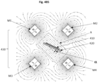
- a suitable magnetic-field generating device (430) for bi-axially orienting at least a part of the platelet-shaped magnetic or magnetizable pigment particles consists of a Halbach cylinder assembly comprising four structures, each one comprising a magnet bar (M1-M4) surrounded by a magnet-wire coil (not shown). As shown in Fig.
- the platelet-shaped magnetic or magnetizable pigment particles in the coating layer (410) on the substrate (420) are exposed to the magnetic field (magnetic field lines shown as lines with arrows pointing from the North Pole to the South Pole) of the magnetic fields of the magnetic-field generating device (430) in one or more areas (shown as a dotted rectangle A) wherein the magnetic field is substantially homogeneous and wherein the magnetic field lines are substantially parallel to each other in said one or more areas and wherein the substrate (420) carrying the coating layer (410) is provided in said one or more areas with the angle ⁇ described herein.
- the magnetic field magnetic field lines shown as lines with arrows pointing from the North Pole to the South Pole
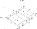
- a suitable magnetic-field generating device (430) for bi-axially orienting at least a part of the platelet-shaped magnetic or magnetizable pigment particles consists of an assembly of eight bar dipole magnets (M1-M8), said assembly comprising a first set comprising a first bar dipole magnet (M4) and two second bar dipole magnets (M1, M6), a second set comprising a first bar dipole magnet (M5) and two second bar dipole magnets (M3; M8) and a first pair of third bar dipole magnets (M2, M7).
- M1-M8 eight bar dipole magnets
- the platelet-shaped magnetic or magnetizable pigment particles in the coating layer (410) on the substrate (420) are exposed to the magnetic field (magnetic field lines shown as lines with arrows pointing from the North Pole to the South Pole) of the magnetic fields of the magnetic-field generating device (430) in one or more areas (shown as a dotted rectangle A) wherein the magnetic field is substantially homogeneous and wherein the magnetic field lines are substantially parallel to each other in said one or more areas and wherein the substrate (420) carrying the coating layer (410) is provided in said one or more areas with the angle ⁇ described herein.
- the magnetic field magnetic field lines shown as lines with arrows pointing from the North Pole to the South Pole
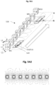
- a suitable magnetic-field generating device (530) for bi-axially so as orient at least a part of the platelet-shaped magnetic or magnetizable pigment particles consists of an assembly comprising nine bar dipole magnets (M1-M9) with alternating North-South magnetic directions and arranged in a row. As shown in Fig.
- the platelet-shaped magnetic or magnetizable pigment particles in the coating layer (510) on the substrate (520) are exposed to the magnetic field (magnetic field lines shown as lines with arrows pointing from the North Pole to the South Pole) of the magnetic fields of the magnetic-field generating device (530) in one or more areas (shown as a dotted parallelepiped A) wherein the magnetic field is substantially homogeneous and wherein the magnetic field lines are substantially parallel to each other in said one or more areas and wherein the substrate (520) carrying the coating layer (510) is provided in said one or more areas with the angle ⁇ described herein.
- the platelet-shaped magnetic or magnetizable pigment particles are mono-axially oriented upon exposure to said devices.
- the substrate (x20) carrying the coating layer (x10) may be disposed on a non-magnetic supporting plate (x40) which is made of one or more non-magnetic materials.
- the methods described herein further comprise, partially simultaneously with or subsequently to step b), the step c) of at least partially curing the coating layer (x10) with the curing unit (x40) described herein so as to at least partially fix the position and orientation of the platelet-shaped magnetic or magnetizable pigment particles in the coating layer (x10) so as to produce the at least partially cured coating layer (x10) described herein, wherein the elevation angle ⁇ described herein is larger than 0° and smaller than 30° (0° ⁇ ⁇ ⁇ 30°) or larger than 150° and smaller than 180° (150° ⁇ ⁇ ⁇ 180°), preferably larger than or equal to about 5° and smaller than 30° (5° ⁇ ⁇ ⁇ 30°) or larger than 150° and smaller than or equal to about 175° (150° ⁇ ⁇ ⁇ 175°), more preferably in the range from about 5° to about 25° (5° ⁇ ⁇ ⁇ 25°) or from about 155° to about 175° (155° ⁇ ⁇ ⁇ 175
- the step c) of at least partially curing the coating layer (x10) with the curing unit (x40) described herein is preferably carried out partially simultaneously with step b).
- said OELs comprising or consisting of the single at least partially cured coating layer (x10) comprising the platelet-shaped magnetic or magnetizable pigment particles in one or more first zones (x10-a) and the platelet-shaped magnetic or magnetizable pigment particles in one or more second zones (x10-b) with magnetically oriented platelet-shaped magnetic or magnetizable pigment particles incorporated therein having an elevation angle ⁇ in the one or more first zones (x10-a) and an additional elevation angle y' in the one or more second zones (x10-b), wherein the elevation angle ⁇ and additional elevation angle ⁇ ' independently are larger than 0° and smaller than 30° (0° ⁇ ⁇ , ⁇ ' ⁇ 30°) or larger than 150° and smaller than 180° (150° ⁇ ⁇ , ⁇ ' ⁇ 180°), preferably larger than or equal to about 5° and smaller than 30° (5
- said OELs comprising or consisting of i) an at least partially cured coating layer (x10) with magnetically oriented platelet-shaped magnetic or magnetizable pigment particles incorporated therein and ii) an at least partially cured second coating layer (x11) with magnetically oriented second platelet-shaped magnetic or magnetizable pigment particles incorporated therein, said at least partially cured second coating layer (x11) partially or fully overlapping the at least partially cured coating layer (x10), wherein substantially all the platelet-shaped magnetic or magnetizable pigment particles in the at least partially cured coating layer (x10) have substantially the same elevation angle ⁇ and substantially all second platelet-shaped magnetic or magnetizable pigment particles in the at least partially cured second coating layer (x11) have substantially the same additional elevation angle y'.
- each of the second platelet-shaped pigment particles is defined by the platelet vector described herein and the platelet vectors of the second platelet-shaped magnetic or magnetizable pigment particles are angled with respect to the two-dimensional surface of the substrate (x20) at the positions of the particles by the additional elevation angle y'.
- the elevation angle ⁇ and additional elevation angle ⁇ ' independently are larger than 0° and smaller than 30° (0° ⁇ ⁇ , ⁇ ' ⁇ 30°) or larger than 150° and smaller than 180° (150° ⁇ ⁇ , ⁇ ' ⁇ 180°), preferably larger than or equal to about 5° and smaller than 30° (5° ⁇ ⁇ , ⁇ ' ⁇ 30°) or larger than 150° and smaller than or equal to about 175° (150° ⁇ ⁇ , ⁇ ' ⁇ 175°), more preferably, in the range from about 5° to about 25° (5° ⁇ ⁇ , ⁇ ' ⁇ 25°) or from about 155° to about 175° (155° ⁇ ⁇ , ⁇ ' ⁇ 175°), said elevation angle ⁇ and additional elevation angle ⁇ ' being different from each other and/or being not coplanar, the method comprises
- said OELs comprising or consisting of i) an at least partially cured coating layer (x10) with magnetically oriented platelet-shaped magnetic or magnetizable pigment particles incorporated therein and ii) an at least partially cured second coating layer (x11) with magnetically oriented second platelet-shaped magnetic or magnetizable pigment particles incorporated therein, said at least partially cured second coating layer being adjacent to ( Fig.
- each of the second platelet-shaped pigment particles is defined by the platelet vector described herein and the platelet vectors of the second platelet-shaped magnetic or magnetizable pigment particles are angled with respect to the two-dimensional surface of the substrate (x20) at the positions of the particles by the additional elevation angle y'.
- the elevation angle ⁇ and additional elevation angle ⁇ ' independently are larger than 0° and smaller than 30° (0° ⁇ ⁇ , ⁇ ' ⁇ 30°) or larger than 150° and smaller than 180° (150° ⁇ ⁇ , ⁇ ' ⁇ 180°), preferably larger than or equal to about 5° and smaller than 30° (5° ⁇ ⁇ , ⁇ ' ⁇ 30°) or larger than 150° and smaller than or equal to about 175° (150° ⁇ ⁇ , ⁇ ' ⁇ 175°), more preferably, in the range from about 5° to about 25° (5° ⁇ ⁇ , ⁇ ' ⁇ 25°) or from about 155° to about 175° (155° ⁇ ⁇ , ⁇ ' ⁇ 175°), said elevation angle ⁇ and additional elevation angle ⁇ ' being different from each other and/or being not coplanar; the method comprises
- Suitable curing units (x40) include equipments for UV-visible curing units comprising a high-power light-emitting-diode (LED) lamp, or an arc discharge lamp, such as a medium-pressure mercury arc (MPMA) or a metal-vapor arc lamp, as the source of the actinic radiation.
- the selective curing units (x50) described herein may comprise one or more fixed or removable photomasks including one or more voids corresponding to a pattern to be formed as a part of the coating layer.
- the one or more selective curing units (x50) may be addressable such as the scanning laser beam disclosed in EP 2 468 423 A1 , an array of light-emitting diodes (LEDs) disclosed in WO 2017/021504 A1 or an actinic radiation LED source (x41) comprising an array of individually addressable actinic radiation emitters disclosed in the co-pending patent application PCT/EP2019/087072 .
- the method described herein comprises a step of applying a composition in the form of the one or more patterns having the shape of an indicium, said step occurring prior to the step a) described herein.
- the step of applying the composition in the form of the one or more patterns described herein may be carried out by a contactless fluid microdispensing process such as curtain coating, spray coating, aerosol jet printing, electrohydrodynamic printing and inkjet printing or may be carried out by a printing process selected from the group consisting of offset, screen printing, rotogravure printing, flexography printing, intaglio printing (also referred in the art as engraved copper plate printing, engraved steel die printing).
- a contactless fluid microdispensing process such as curtain coating, spray coating, aerosol jet printing, electrohydrodynamic printing and inkjet printing
- a printing process selected from the group consisting of offset, screen printing, rotogravure printing, flexography printing, intaglio printing (also referred in the art as engraved copper plate printing, engraved steel die printing).
- printing apparatuses comprising one or more printing units, one or more magnetic-field-generating devices (x30) and one or more curing units (x40), the one or more printing units, the one more magnetic-field-generating devices (x30) and the one or more curing units (x40) being arranged in sequential and alternating stationary locations, that is so that a stationary magnetic-field-generating device (x30) is disposed after a stationary printing unit and before a stationary curing unit.
- printing apparatuses comprising a rotating magnetic cylinder and the one or more magnetic-field generating devices (x30) described herein, wherein said one or more magnetic-field generating devices (x30) are mounted to circumferential or axial grooves of the rotating magnetic cylinder as well as printing assemblies comprising a flatbed printing unit and one or more of the magnetic-field generating devices (x30) described herein, wherein said one or more magnetic-field generating devices (x30) are mounted to recesses of the flatbed printing unit.
- the rotating magnetic cylinder is meant to be used in, or in conjunction with, or being part of a printing or coating equipment, and bearing one or more of the magnetic-field generating devices (x30) described herein.
- the rotating magnetic cylinder is part of a rotary, sheet-fed or web-fed industrial printing press that operates at high printing speed in a continuous way.
- the flatbed printing unit is meant to be used in, or in conjunction with, or being part of a printing or coating equipment, and bearing one or more of the magnetic-field generating devices (x30) described herein.
- the flatbed printing unit is part of a sheet-fed industrial printing press that operates in a discontinuous way.
- the printing apparatuses comprising the rotating magnetic cylinder described herein or the flatbed printing unit described herein may include a substrate feeder for feeding a substrate such as those described herein having thereon the coating layer (x10, x11) comprising the platelet-shaped magnetic or magnetizable pigment particles described herein.
- the substrate is fed by the substrate feeder under the form of sheets or a web.
- the substrate is fed under the form of sheets.
- the printing apparatuses comprising the rotating magnetic cylinder described herein or the flatbed printing unit described herein may include a coating or printing unit for applying the radiation curable coating composition comprising the platelet-shaped magnetic or magnetizable pigment particles described herein on the substrate (x20) described herein,
- the coating or printing unit works according to a rotary, continuous process.
- the coating or printing unit works according to a linear, discontinuous process.
- the printing apparatuses comprising the rotating magnetic cylinder described herein or the flatbed printing unit described herein may include the curing unit (x40) described herein for at least partially curing the radiation curable coating composition comprising the platelet-shaped magnetic or magnetizable pigment particles that have been magnetically oriented by the magnetic-field generating devices (x30) described herein, thereby fixing the orientation and position of the pigment particles to produce the one or more OELS described herein.
- Examples according to the present invention E1-E8 exhibited an eye-catching visual appearance upon tilting about a horizontal/latitudinal axis, wherein eye-catching visual appearance is seen as a sharp and contrasted switch-on / switch off effect of the brightness and consists off an increase of the brightness value to reach a maximum value of brightness and then a decrease of said brightness within the viewing/observation angles about -45° and about +45°,
- a magnetic assembly (530) was used to bi-axially orient the pigment particles.
- the magnetic assembly (530) comprised nine bar dipole magnets (M1-M9).
- Each of the nine bar dipole magnets (M1-M9) had the following dimensions: 100 mm (L1) ⁇ 10 mm (L2) ⁇ 10 mm (L3).
- the magnetic field generating device (530) was embedded in a non-magnetic holder made of polyoxymethylene (POM) (not shown) having the following dimensions: 250 mm ⁇ 150 mm ⁇ 12 mm.
- the nine bar dipole magnets (M1-M9) were made of NdFeB N40.
- the nine bar dipole magnets (M1-M9) were disposed in a row at a distance (d1) of about 10 mm from each other, the top surface of the nine bar dipole magnets (M1-M9) being flush.
- the magnetic axis of each of the nine bar dipole magnets (M1-M9) was substantially parallel to the thickness (L3) of said magnets, the magnetic direction of two neighboring magnets (M1-M9) pointing in opposite direction (alternating magnetization).
- the magnetic field was substantially homogeneous and the magnetic field lines were substantially coplanar in the area A.
- a magnetic field generating device (630) was used to mono-axially orient the pigment particles.
- the magnetic field generating device (630) comprised two bar dipole magnets (M1, M2) and two pole pieces (P1, P2).
- Each of the two bar dipole magnets (M1, M2) had the following dimensions: 40 mm (L1) ⁇ 40 mm (L2) ⁇ 10 mm (L3).
- the two bar dipole magnets (M1, M2) were made of NdFeB N42.
- the two bar dipole magnets (M1, M2) were at a distance (d1) of about 40 mm from each other.
- the magnetic axis of each of the two bar dipole magnets (M1, M2) was substantially parallel to the length (L1) of said magnets, the magnetic direction of said two bar dipole magnets (M1, M2) pointing in the same direction.
- Each of the two pole pieces (P1, P2) had the following dimensions: 60 mm (L4) ⁇ 40 mm (L5) ⁇ 3 mm (L6).
- the two pole pieces (P1, P2) were made of iron (ARMCO ® ).
- the two bar dipole magnets (M1, M2) and the two pole pieces (P1, P2) were disposed such as to form a rectangular cuboid with a centered rectangular cuboid void, said void consisting of the area A wherein the magnetic field was substantially homogeneous and wherein the magnetic field lines were substantially parallel to each other, such that the distance (d2) between the two pole pieces (P1, P2) was about 40 mm, i.e. the distance (d2) between the two pole pieces (P1, P2) was the length (L1) of the two bar dipole magnets (M1, M2).
- the UV-Vis curable screen printing ink of Table 1 was applied onto on a piece of PET (BG71 Colour Laser Printer & Copier OHP Film from Folex 100 micrometers thick, 45 mm ⁇ 30 mm) (520) so as to form a coating layer (40 mm ⁇ 25 mm) (510), wherein said application step was carried out with a laboratory screen printing device using a 90T screen so as to form a coating layer (510) having a thickness of about 20 ⁇ m.
- the substrate (520) was placed on top of the center of a supporting plate (300 mm ⁇ 40 mm ⁇ 1 mm) made of high density polyethylene (HDPE).
- the supporting plate carrying the substrate (520) and the coating layer (510) were moved at a speed of about 10 cm/sec beside the magnetic-field generating device (530) (as illustrated in Fig.
- the supporting plate carrying the substrate (520) and the coating layer (510) was concomitantly moved while adopting an angle ⁇ , formed by the coating layer (510) and a tangent to the magnetic field lines of the magnetic field of the magnetic-field-generating device (530) within the area A wherein the magnetic field was homogeneous, said angle ⁇ having a value of about 1° (E1), 5° (E2), 10° (E3), 20° (E4), 25° (E5), 30° (C1), 40° (C2) and 50° (C3).
- the coating layers (510) were independently at least partially cured by a curing unit (540) (UV LED lamp (FireFly 395 nm, 4W/cm 2 , from Phoseon) disposed above the substrate path at a distance (d4) of about 15 mm for the center of the length (L1) of the bar dipole magnet (M1-M9), beside the space between the eighth and ninth dipole magnets (M8 and M9) and beside the ninth bar dipole magnet (M9) at a distance (d3) of about 10 mm, as illustrated in Fig. 5A1-3 .
- a curing unit (540) UV LED lamp (FireFly 395 nm, 4W/cm 2 , from Phoseon) disposed above the substrate path at a distance (d4) of about 15 mm for the center of the length (L1) of the bar dipole magnet (M1-M9), beside the space between the eighth and ninth dipole magnets (M8 and M9) and beside the ninth bar dipole magnet (M9) at a distance (d
- the UV-Vis curable screen printing ink of Table 1 was applied onto on a piece of PET (BG71 Colour Laser Printer & Copier OHP Film from Folex 100 micrometers thick, 45 mm ⁇ 30 mm) (520) so as to form a first coating layer (510) having the shape of "A" (6 mm) (510), wherein said application step was carried out with a laboratory screen printing device using a 90T screen so as to form a coating layer (510) having a thickness of about 20 ⁇ m.
- the substrate (520) was placed on top of the center of a supporting plate (300 mm ⁇ 40 mm ⁇ 1 mm) made of high density polyethylene (HDPE).
- the supporting plate carrying the substrate (520) and the coating layer (510) was moved at a speed of about 10 cm/sec beside the magnetic-field generating device (530) (as illustrated in Fig.
- the supporting plate carrying the substrate (520) and the coating layer (510) were concomitantly moved while adopting an angle ⁇ , formed by the coating layer (510) and a tangent to the magnetic field lines of the magnetic field of the magnetic-field-generating device (530) within the area A wherein the magnetic field was homogeneous, having a value of about 20°.
- the first coating layer (510) was at least partially cured by the curing unit (540) under the same conditions/position positions as for E1-E5 and C1-C3.
- the UV-Vis curable screen printing ink of Table 1 was applied on top of the already applied coating layer (510) so as to form a second coating layer (511) having the shape of "T" (6 mm), wherein said application step was carried out with a laboratory screen printing device using a 90T screen so as to form a coating layer (511) having a thickness of about 20 ⁇ m.
- the substrate (520) was exposed to the magnetic field of the magnetic-field-generating device (530) under the same conditions as for the first coating layer (510) except that the angle a ⁇ was about 160°.
- the second coating layer (511) was at least partially cured by the curing unit (540) under the same conditions/position positions as for E1-E5 and C1-C3.
- the UV-Vis curable screen printing ink of Table 1 was applied onto on a piece of PET (BG71 Colour Laser Printer & Copier OHP Film from Folex 100 micrometers thick, 45 mm ⁇ 30 mm) (620) so as to form a coating layer (40 mm ⁇ 25 mm) (610), wherein said application step was carried out with a laboratory screen printing device using a 90T screen so as to form a coating layer (610) having a thickness of about 20 ⁇ m.
- the substrate (620) was placed on top of the center of a supporting plate (60 mm ⁇ 40 mm ⁇ 1 mm) made of high density polyethylene (HDPE).
- a supporting plate 60 mm ⁇ 40 mm ⁇ 1 mm
- the supporting plate carrying the substrate (620) and the coating layer (610) were disposed in the center of the void of the magnetic assembly (630) as illustrated in Fig. 6 while adopting angle ⁇ , formed by the coating layer (610) and a tangent to magnetic field lines of the magnetic-field-generating device (630) within the area A wherein the magnetic field was homogeneous, having a value of about 20°.
- the coating layer (610) was at least partially cured by a curing unit (640) (UV LED lamp (FireFly 395 nm, 4W/cm 2 , from Phoseon) as illustrated in Fig. 6B1 .
- a curing unit 640
- UV LED lamp FireFly 395 nm, 4W/cm 2 , from Phoseon
- the supporting plate carrying the substrate (620) and the coating layer (610) were moved at a distance (d i ) of about 1 cm away from the magnetic assembly (630), the coating layer (610) was cured upon exposure during about 0.5 second to a UV-LED-lamp (640) from Phoseon (Type FireFlex 50 ⁇ 75 mm, 395 nm, 8W/cm 2 ), as illustrated in Fig. 6B2 .
- the correlation between the angles ⁇ during the method described hereabove and the elevation angles ⁇ was assessed by measuring said elevation angles y by using the conoscopic scatterometer measurements according to the method disclosed in WO 2019/038371 A1 and by measuring the elevation angles of a selection of five adjacent pigment particles on a SEM picture (ZEISS EVO HD15, using standard method of sample preparation by embedding into an epoxy matrix (Technicol 9461) with the following dimensions: 10 mm x 10 mm x30 mm) a cross-section of the coating layer (x10). Results are provided in Table 2.
- the conoscopic scatterometer measurements have been performed by using a conoscopic scatterometer as described in WO 2019/038371 A1 , Fig. 4A (obtained from Eckhartd Optics LLC, 5430 Jefferson Ct, White Bear Lake, MN 55110; http://eckop.com).
- the elevation angles ⁇ were measured on a coating layer surface of about 1 mm 2 , i.e. the reported values were averaged on about one thousand particles
- SEM measurements have been performed by using a SEM microscope (ZEISS EVO HD15, magnification x500) on a microtome slice of the samples (slice plane perpendicular to the substrate surface and the coating layer thickness, and perpendicular to the tilting axis, as illustrated in Fig. 3 ).
- the substrates carrying the coating layer were first independently embedded in an epoxy resin (Technicol 9461) that was left to dry for 24 hours at room temperature before cutting and polishing the microtome slice to produce samples with the following dimensions: 10 mm ⁇ 10 mm ⁇ 30 mm. The reported values were averaged on five particles.
- the samples were disposed and fixed with a scotch tape on a paper substrate (respectively black or white).
- the assemblies carrying the coating layer (x10, x11), the PET substrate (x20) and the paper substrate were independently disposed on a tilting holder in an integration sphere (internal diameter 1m from Dongguan Yaoke Instrument) as illustrated in Fig. 10 .
- the assemblies were illuminated with an illumination source (light bulb (30W, at 100% power) disposed at a distance of about 100 cm from the PET substrate surface.
- a camera (Nikon D800, lens Nikkor 105/2.8 ED, shutter speed 1/200 sec, aperture f/36, ISO 6400) was disposed on an imaginary line between the assemblies and the illumination source, at a distance of about 50 cm from the PET substrate.
- the images were acquired at 3680x2456 pixels (TIFF).
- the brightness of E1-E5, E7-E8 and C1-C3 were assessed using Adobe Photoshop ® and by calculating the brightness average of a 100 pixels ⁇ 100 pixels area of each individual assembly comprising the coating layer (x10, x11), the PET substrate (x20) and the paper substrate.
- Fig. 7B illustrates a graph obtained by reporting the brightness of E1-E5 and C1-C3
- Fig. 9 illustrate graphs obtained by reporting the brightness of E7-E8 at different observation angles ⁇ varying from -50° to +70° (x-axis : observation angles ⁇ [in degrees, °]; y-axis : brightness (arbitrary units)).
- the brightness curves are asymmetric as a result of the slightly less illuminated regions of the sphere due to the presence of the plate (P).
- the optical effects layers of E1-E5 (0° ⁇ ⁇ ⁇ 30°, in particular 5° ⁇ ⁇ ⁇ 30°, 5° ⁇ ⁇ ⁇ 25°) exhibited an eye-catching effect and an easily observable increase of the brightness to reach a maximum value of brightness and then a decrease of said brightness value within the viewing/observation angles about -45° and about +45°.
- E1 (1°) exhibited a maximum brightness at an observation angle ⁇ of about -10°
- E2 (5°) exhibited a maximum brightness at an observation angle ⁇ of about -15°
- E3 (10°) exhibited a maximum value of brightness at an observation angle ⁇ of about -25°
- E4 exhibited a maximum value of brightness at an observation angle ⁇ of about -35°
- E5 exhibited a maximum value of brightness at an observation angle ⁇ of about -40°.
- the first coating layer (510 in Fig. 5 , 310 in Fig. 3D ) of E6 having the shape of a "A" was visible at observation angles from about 0° to about +50° with a maximum value of brightness at an observation angle of about +40°
- the second/top coating layer (511, in Fig, 5 , 311 Fig. 3D ) having the shape of a "T" was visible from -15° to about -65° with a maximum value of brightness at an observation angle of about -35°.
- E7-E8 exhibited an easily observable increase and decrease of the brightness with a maximum value of brightness at an observation angles ⁇ of about - (20°-25°) for E7 and -(10°-15°) for E8.
Landscapes
- Credit Cards Or The Like (AREA)
- Printing Methods (AREA)
- Application Of Or Painting With Fluid Materials (AREA)
- Laminated Bodies (AREA)
- Inspection Of Paper Currency And Valuable Securities (AREA)
Claims (15)
- Sicherheitsdokument oder dekorativer Artikel, das/der ein Substrat (x20) mit einer zweidimensionalen Oberfläche und eine oder mehrere Optikeffektschichten (OELs) auf dem Substrat (x20) aufweist, wobeidie eine oder mehrere Optikeffektschichten (OEL) magnetisch orientierte plättchenförmige magnetische oder magnetisierbare Pigmentpartikel aufweisen, die eine Hauptachse X haben und sich in einer zumindest teilweise ausgehärteten Beschichtungsschicht (x10) befinden, wobeieine Orientierung der plättchenförmigen Pigmentpartikel durch einen Plättchenvektor definiert ist, der der Vektor parallel zur Hauptachse X des Partikels ist, wobei die Plättchenvektoren benachbarter plättchenförmiger magnetischer oder magnetisierbarer Pigmentpartikel im Wesentlichen parallel zueinander sind,wobei die Plättchenvektoren der plättchenförmigen magnetischen oder magnetisierbaren Pigmentpartikel in Bezug auf die zweidimensionale Oberfläche des Substrats (x20) an den Positionen der Partikel um einen Elevationswinkel (y) abgewinkelt sind, dadurch gekennzeichnet, dass der Elevationswinkel (y) größer als 0° und kleiner als 30° (0° < γ < 30°) oder größer als 150° und kleiner als 180° (150° < γ < 180°) ist,so dass die eine oder mehrere Optikeffektschichten (OELs) einen Helligkeitsanstieg bis zu einem maximalen Helligkeitswert und einen Helligkeitsabfall innerhalb eines Betrachtungswinkels von -45° bis +45° des Substrats (x20) aufweisen.
- Sicherheitsdokument oder Artikel nach Anspruch 1, wobei zumindest ein Teil der plättchenförmigen magnetischen oder magnetisierbaren Partikel aus plättchenförmigen optisch variablen magnetischen oder magnetisierbaren Pigmentpartikeln besteht.
- Sicherheitsdokument oder Artikel nach Anspruch 1, wobei zumindest ein Teil der plättchenförmigen magnetischen oder magnetisierbaren Partikel aus plättchenförmigen magnetischen oder magnetisierbaren Pigmentpartikeln besteht, die eine metallische Farbe, vorzugsweise eine silberne Farbe oder eine goldene Farbe, aufweisen.
- Sicherheitsdokument oder Artikel nach einem der Ansprüche 1 bis 3, wobei die plättchenförmigen magnetischen oder magnetisierbaren Partikel im Wesentlichen parallel zueinander angeordnet sind.
- Sicherheitsdokument oder Artikel nach einem der Ansprüche 1 bis 4, das/der ferner einen oder mehrere Zeichen aufweist, wobei das eine oder die mehreren Zeichen zwischen dem Substrat (x20) und der einen oder den mehreren Optikeffektschichten (OELs) vorhanden sind.
- Sicherheitsdokument oder Artikel nach einem der Ansprüche 1 bis 5, wobei die eine oder die mehreren Optikeffektschichten (OEL) die magnetisch orientierten plättchenförmigen magnetischen oder magnetisierbaren Pigmentpartikel in der zumindest teilweise ausgehärteten Beschichtungsschicht (x10) aufweisen und magnetisch orientierte zweite plättchenförmige magnetische oder magnetisierbare Pigmentpartikel in einer zumindest teilweise ausgehärteten zweiten Beschichtungsschicht (x11) aufweisen, wobei die zumindest teilweise ausgehärtete zweite Beschichtungsschicht (x11) entweder die zumindest teilweise ausgehärtete Beschichtungsschicht (x10) zumindest teilweise oder vollständig überlappt, oder die zumindest teilweise ausgehärtete zweite Beschichtungsschicht (x11) an die zumindest teilweise ausgehärtete Beschichtungsschicht (x10) angrenzt, oder die zumindest teilweise ausgehärtete zweite Beschichtungsschicht (x11) von der zumindest teilweise ausgehärteten Beschichtungsschicht (x10) beabstandet ist, wobei die Plättchenvektoren der zweiten plättchenförmigen magnetischen oder magnetisierbaren Pigmentpartikel in Bezug auf die zweidimensionale Oberfläche des Substrats (x20) an den Positionen der Partikel in der zumindest teilweise ausgehärteten zweiten Beschichtungsschicht (x11) um einen zusätzlichen Elevationswinkel γ' abgewinkelt sind, wobei der zusätzliche Elevationswinkel γ' größer als 0° und kleiner als 30° (0° < γ' < 30°) oder größer als 150° und kleiner als 180° (150° < γ' < 180°) ist, wobei der Elevationswinkel γ und der zusätzliche Elevationswinkel γ' voneinander verschieden und/oder nicht koplanar sind.
- Sicherheitsdokument oder Artikel nach einem der Ansprüche 1 bis 6, wobei der Elevationswinkel γ größer oder gleich etwa 5° und kleiner als 30° (5° ≤ γ < 30°) oder größer als 150° und kleiner oder gleich etwa 175° (150° < γ ≤ 175°), vorzugsweise im Bereich von etwa 5° bis etwa 25° (5° ≤ γ ≤ 25°) oder von etwa 155° bis etwa 175° (155° ≤ γ ≤ 175°), ist.
- Verfahren zur Herstellung einer Optikeffektschicht (OEL) auf einem Substrat (x20) mit einer zweidimensionalen Oberfläche, wobei das Verfahren die Schritte aufweist:a) Aufbringen einer durch Strahlung härtbaren Beschichtungszusammensetzung, die plättchenförmige magnetische oder magnetisierbare Pigmentpartikel aufweist, auf die Oberfläche des Substrats (x20), wobei sich die durch Strahlung härtbare Beschichtungszusammensetzung in einem ersten flüssigen Zustand befindet, um eine Beschichtungsschicht (x10) zu bilden;b) Aussetzen der Beschichtungsschicht (x10) einem Magnetfeld einer Magnetfelderzeugungsvorrichtung (x30) in einem oder mehreren Bereichen, in denen das Magnetfeld im Wesentlichen homogen ist, um zumindest einen Teil der plättchenförmigen magnetischen oder magnetisierbaren Pigmentpartikel zu orientieren, wobei das Substrat (x20), das die Beschichtungsschicht (x10) trägt, in dem einen oder den mehreren Bereichen vorgesehen ist, in denen das Magnetfeld im Wesentlichen homogen ist, wobei ein Winkel α, der durch die Beschichtungsschicht (x10) und eine Tangente an Magnetfeldlinien des Magnetfeldes innerhalb des einen oder der mehreren Bereiche gebildet wird, in denen das Magnetfeld im Wesentlichen homogen ist, größer als 0° und kleiner als 30° (0° < α < 30°) oder größer als 150° und kleiner als 180° (150° < α < 180°) ist,c) teilweise gleichzeitig mit oder im Anschluss an Schritt b) einen Schritt des zumindest teilweisen Aushärtens der Beschichtungsschicht (x10) mit einer Aushärtungseinheit (x40), um die Position und Orientierung der plättchenförmigen magnetischen oder magnetisierbaren Pigmentpartikel in der Beschichtungsschicht (x10) zumindest teilweise zu fixieren, um eine zumindest teilweise ausgehärtete Beschichtungsschicht (x10) herzustellen,wobei eine Orientierung der plättchenförmigen Pigmentpartikel durch einen Plättchenvektor definiert ist, der der Vektor parallel zur Hauptachse X des Partikels ist, wobei die Plättchenvektoren benachbarter plättchenförmiger magnetischer oder magnetisierbarer Pigmentpartikel im Wesentlichen parallel zueinander sind, und wobei die Plättchenvektoren der plättchenförmigen magnetischen oder magnetisierbaren Pigmentpartikel in Bezug auf die zweidimensionale Oberfläche des Substrats (x20) an den Positionen der Partikel um einen Elevationswinkel γ abgewinkelt sind, wobei der Elevationswinkel γ größer als 0° und kleiner als 30° (0° < γ < 30°) oder größer als 150° und kleiner als 180° (150° < γ < 180°) ist.
- Verfahren nach Anspruch 8, wobei die plättchenförmigen magnetischen oder magnetisierbaren Pigmentpartikel eine zweite Hauptachse Y haben und die Orientierung der plättchenförmigen Pigmentpartikel ferner durch einen zweiten Plättchenvektor definiert ist, der der Vektor parallel zur zweiten Hauptachse Y der Partikel ist, und wobei der Schritt b) des Aussetzens der Beschichtungsschicht (x10) so durchgeführt wird, um zumindest einen Teil der plättchenförmigen magnetischen oder magnetisierbaren Pigmentpartikel biaxial zu orientieren, so dass die Plättchenvektoren benachbarter plättchenförmiger magnetischer oder magnetisierbarer Pigmentpartikel im Wesentlichen parallel zueinander sind und die zweiten Plättchenvektoren der benachbarten plättchenförmigen magnetischen oder magnetisierbaren Pigmentpartikel im Wesentlichen parallel zueinander sind.
- Verfahren nach Anspruch 9, wobei der Schritt c) teilweise gleichzeitig mit dem Schritt b) durchgeführt wird.
- Verfahren nach einem der Ansprüche 8 bis 10, wobei die Optikeffektschicht (OEL) die zumindest teilweise ausgehärtete Beschichtungsschicht (x10), die die plättchenförmigen magnetischen oder magnetisierbaren Pigmentpartikel aufweist, und, zumindest teilweise auf der zumindest teilweise ausgehärteten Beschichtungsschicht (x10), eine zumindest teilweise ausgehärtete zweite Beschichtungsschicht (x11) aufweist, die zweite plättchenförmige magnetische oder magnetisierbare Pigmentpartikel aufweist, wobei eine Orientierung jedes der zweiten plättchenförmigen Pigmentpartikel durch den Plättchenvektor definiert ist, der der Vektor parallel zu der Hauptachse X der zweiten plättchenförmigen Pigmentpartikel ist, wobei die Plättchenvektoren benachbarter zweiter plättchenförmiger magnetischer oder magnetisierbarer Pigmentpartikel im Wesentlichen parallel zueinander sind,wobei die Plättchenvektoren der zweiten plättchenförmigen magnetischen oder magnetisierbaren Pigmentpartikel in Bezug auf die zweidimensionale Oberfläche des Substrats (x20) an den Positionen der Partikel um einen zusätzlichen Elevationswinkel γ' abgewinkelt sind, der größer als 0° und kleiner als 30° (0° < γ' < 30°) oder größer als 150° und kleiner als 180° (150° < γ' < 180°) ist, wobei der Elevationswinkel γ und der zusätzliche Elevationswinkel γ' voneinander verschieden und/oder nicht koplanar sind,wobei das Verfahren ferner aufweist:im Anschluss an Schritt c), einen Schritt d) des zumindest teilweisen oder vollständigen Aufbringens einer zweiten durch Strahlung härtbaren Beschichtungszusammensetzung, die die zweiten plättchenförmigen magnetischen oder magnetisierbaren Pigmentpartikel aufweist, auf die zumindest teilweise ausgehärtete Beschichtungsschicht (x10), wobei sich die zweite durch Strahlung härtbare Beschichtungszusammensetzung in einem ersten flüssigen Zustand befindet, um eine zweite Beschichtungsschicht (x11) zu bilden, wobei die zweite durch Strahlung härtbare Beschichtungszusammensetzung die gleiche ist wie die durch Strahlung härtbare Beschichtungszusammensetzung von Schritt a) oder sich von dieser unterscheidet;einen Schritt e) des Aussetzens der zweiten Beschichtungsschicht (x11) einem zweiten Magnetfeld einer zweiten Magnetfelderzeugungsvorrichtung in einem oder mehreren Bereichen, in denen das zweite Magnetfeld homogen ist, um zumindest einen Teil der zweiten plättchenförmigen magnetischen oder magnetisierbaren Pigmentpartikel zu orientieren, wobei das Substrat (x20), das die zweite Beschichtungsschicht (x11) trägt, in dem einen oder den mehreren Bereichen vorgesehen ist, in denen das Magnetfeld im Wesentlichen homogen ist, wobei ein Winkel α', der durch die zweite Beschichtungsschicht (x11) und eine Tangente an Magnetfeldlinien des zweiten Magnetfelds innerhalb des einen oder der mehreren Bereiche gebildet wird, in denen das Magnetfeld homogen ist, größer als 0° und kleiner als 30° (0° < α' < 30°) oder größer als 150° und kleiner als 180° (150° < α' < 180°) ist, wobei die zweite Magnetfelderzeugungsvorrichtung die gleiche ist oder sich von der Magnetfelderzeugungsvorrichtung von Schritt b) unterscheidet, wobei α' sich von α unterscheidet; undf) teilweise gleichzeitig mit oder im Anschluss an den Schritt e), bei dem die zweite Beschichtungsschicht (x11) dem zweiten Magnetfeld ausgesetzt wird, einen Schritt des zumindest teilweisen Aushärtens der zweiten Beschichtungsschicht (x11) mit einer Aushärtungseinheit (x40), um die Position und Orientierung der zweiten plättchenförmigen magnetischen oder magnetisierbaren Pigmentpartikel in der zweiten Beschichtungsschicht (x11) zumindest teilweise zu fixieren, um die zumindest teilweise ausgehärtete zweite Beschichtungsschicht (x11) herzustellen.
- Verfahren nach einem der Ansprüche 8 bis 10, wobei die Optikeffektschicht (OEL) die zumindest teilweise ausgehärtete Beschichtungsschicht (x10), die die plättchenförmigen magnetischen oder magnetisierbaren Pigmentpartikel aufweist, und eine zumindest teilweise ausgehärtete zweite Beschichtungsschicht (x11) aufweist, die zweite plättchenförmige magnetische oder magnetisierbare Pigmentpartikel aufweist, wobei eine Orientierung jedes der zweiten plättchenförmigen Pigmentpartikel durch den Plättchenvektor definiert ist, der der Vektor parallel zu der Hauptachse X der zweiten plättchenförmigen Pigmentpartikel ist, wobei die Plättchenvektoren benachbarter zweiter plättchenförmiger magnetischer oder magnetisierbarer Pigmentpartikel im Wesentlichen parallel zueinander sind, wobei die zumindest teilweise ausgehärtete zweite Beschichtungsschicht (x11) an die zumindest teilweise ausgehärtete Beschichtungsschicht (x10) angrenzt oder von dieser beabstandet ist, wobei die Plättchenvektoren der zweiten plättchenförmigen magnetischen oder magnetisierbaren Pigmentpartikel in Bezug auf die zweidimensionale Oberfläche des Substrats (x20) an den Positionen der Partikel um einen zusätzlichen Elevationswinkel γ' in der zumindest teilweise ausgehärteten zweiten Beschichtungsschicht (x11) abgewinkelt sind, wobei der zusätzliche Elevationswinkel γ' größer als 0° und kleiner als 30° (0° < γ' < 30°) oder größer als 150° und kleiner als 180° (150° < γ' < 180°°) ist, wobei der Elevationswinkel γ und der zusätzliche Elevationswinkel γ' voneinander verschieden und/oder nicht koplanar sind, wobei das Verfahren ferner aufweist:im Anschluss an Schritt c), einen Schritt d) des Aufbringens einer zweiten durch Strahlung härtbaren Beschichtungszusammensetzung, die die zweiten plättchenförmigen magnetischen oder magnetisierbaren Pigmentpartikel aufweist, wobei sich die zweite durch Strahlung härtbare Beschichtungszusammensetzung in einem ersten flüssigen Zustand befindet, um eine zweite Beschichtungsschicht (x11) zu bilden, wobei die durch Strahlung härtbare Beschichtungszusammensetzung die gleiche ist wie die durch Strahlung härtbare Beschichtungszusammensetzung von Schritt a) oder sich von dieser unterscheidet und die zweite Beschichtungsschicht (x11) an die zumindest teilweise ausgehärtete Beschichtungsschicht (x10) angrenzt oder von dieser beabstandet ist;einen Schritt e) des Aussetzens der zweiten Beschichtungsschicht (x11) einem zweiten Magnetfeld einer zweiten Magnetfelderzeugungsvorrichtung in einem oder mehreren Bereichen, in denen das Magnetfeld homogen ist, um zumindest einen Teil der zweiten plättchenförmigen magnetischen oder magnetisierbaren Pigmentpartikel zu orientieren, wobei das Substrat (x20), das die zweite Beschichtungsschicht (x11) trägt, in dem einen oder den mehreren Bereichen vorgesehen ist, in denen das Magnetfeld im Wesentlichen homogen ist, wobei ein Winkel α',der durch die zweite Beschichtungsschicht (x11) und eine Tangente an Magnetfeldlinien des zweiten Magnetfelds innerhalb des einen oder der mehreren Bereiche gebildet wird, in denen das Magnetfeld im Wesentlichen homogen ist, und der Winkel größer als 0° und kleiner als 30° (0° < α' < 30°) oder größer als 150° und kleiner als 180° (150° < α' < 180°) ist, wobei die zweite Magnetfelderzeugungsvorrichtung die gleiche ist wie die Magnetfelderzeugungsvorrichtung von Schritt b) oder sich von dieser unterscheidet; wobei α' sich von α unterscheidet;f) teilweise gleichzeitig mit oder im Anschluss an den Schritt e), bei dem die zweite Beschichtungsschicht (x11) dem zweiten Magnetfeld ausgesetzt wird, einen Schritt des zumindest teilweisen Aushärtens der zweiten Beschichtungsschicht (x11) mit einer Aushärtungseinheit (x40), um die Position und Orientierung der zweiten plättchenförmigen magnetischen oder magnetisierbaren Pigmentpartikel in der zweiten Beschichtungsschicht (x11) zumindest teilweise zu fixieren, um die zumindest teilweise ausgehärtete zweite Beschichtungsschicht (x11) herzustellen.
- Verfahren nach Anspruch 11 oder 12, wobei der Winkel α' größer als oder gleich etwa 5° und kleiner als 30° (5° ≤ α' < 30°) oder größer als 150° und kleiner als oder gleich etwa 175° (150° < α' ≤ 175°), vorzugsweise im Bereich von etwa 5° bis etwa 25° (5° ≤ α' ≤ 25°) oder von etwa 155° bis etwa 175° (155° ≤ α' ≤ 175°), ist.
- Verfahren nach einem der Ansprüche 8 bis 13, wobei der Winkel α größer als oder gleich etwa 5° und kleiner als 30° (5° ≤ α < 30°) oder größer als 150° und kleiner als oder gleich etwa 175° (150° < α ≤ 175°), vorzugsweise im Bereich von etwa 5° bis etwa 25° (5° ≤ α ≤ 25°) oder von etwa 155° bis etwa 175° (155° ≤ α ≤ 175°), ist.
- Optikeffektschicht (OEL), hergestellt nach dem Verfahren nach einem der Ansprüche 8 bis 14.
Priority Applications (2)
| Application Number | Priority Date | Filing Date | Title |
|---|---|---|---|
| RS20241079A RS66054B1 (sr) | 2020-09-02 | 2021-08-30 | Sigurnosni dokumenti ili artikli koji sadrže slojeve sa optičkim efektom koji sadrže magnetne ili magnetizabilne čestice pigmenta i metode za proizvodnju navedenih slojeva sa optičkim efektom |
| MA67278A MA67278B1 (fr) | 2020-09-02 | 2021-08-30 | Documents de sécurité ou articles comprenant des couches à effet optique comprenant des particules de pigment magnétiques ou magnétisables et procédés de production desdites couches à effet optique |
Applications Claiming Priority (2)
| Application Number | Priority Date | Filing Date | Title |
|---|---|---|---|
| EP20194060 | 2020-09-02 | ||
| PCT/EP2021/073863 WO2022049024A1 (en) | 2020-09-02 | 2021-08-30 | Security documents or articles comprising optical effect layers comprising magnetic or magnetizable pigment particles and methods for producing said optical effect layers |
Publications (2)
| Publication Number | Publication Date |
|---|---|
| EP4208349A1 EP4208349A1 (de) | 2023-07-12 |
| EP4208349B1 true EP4208349B1 (de) | 2024-08-07 |
Family
ID=72340255
Family Applications (1)
| Application Number | Title | Priority Date | Filing Date |
|---|---|---|---|
| EP21769960.2A Active EP4208349B1 (de) | 2020-09-02 | 2021-08-30 | Sicherheitsdokumente oder -artikel mit optischen effektschichten mit magnetischen oder magnetisierbaren pigmentpartikeln und verfahren zur herstellung der besagten optischen effektschichten |
Country Status (23)
| Country | Link |
|---|---|
| US (1) | US12049097B2 (de) |
| EP (1) | EP4208349B1 (de) |
| JP (1) | JP7787156B2 (de) |
| KR (1) | KR20230058688A (de) |
| CN (1) | CN116171227A (de) |
| AR (1) | AR123351A1 (de) |
| AU (1) | AU2021337170A1 (de) |
| BR (1) | BR112023003507A2 (de) |
| CA (1) | CA3193623A1 (de) |
| CL (1) | CL2023000590A1 (de) |
| CO (1) | CO2023003688A2 (de) |
| CU (1) | CU24764B1 (de) |
| DK (1) | DK4208349T3 (de) |
| HU (1) | HUE069309T2 (de) |
| MA (1) | MA67278B1 (de) |
| MX (1) | MX2023002566A (de) |
| PL (1) | PL4208349T3 (de) |
| PT (1) | PT4208349T (de) |
| RS (1) | RS66054B1 (de) |
| SA (1) | SA523442613B1 (de) |
| TW (1) | TWI900643B (de) |
| WO (1) | WO2022049024A1 (de) |
| ZA (1) | ZA202304060B (de) |
Families Citing this family (12)
| Publication number | Priority date | Publication date | Assignee | Title |
|---|---|---|---|---|
| MX2023014535A (es) * | 2021-06-11 | 2024-01-31 | Sicpa Holding Sa | Capas de efecto optico que comprenden particulas de pigmento magneticas o magnetizables y metodos para producir dichas capas de efecto optico. |
| CN115527303A (zh) * | 2022-08-19 | 2022-12-27 | 北京柯斯元科技有限公司 | 一种多层磁片防伪结构 |
| WO2024218531A1 (en) * | 2023-04-20 | 2024-10-24 | Htc Technology Consulting | Magnetic alignment of magnetically orientable pigments in an ink with superimposed magnetic fields. |
| CN116714352B (zh) * | 2023-05-17 | 2025-12-05 | 惠州市华阳光学技术有限公司 | 定磁装置及定磁方法 |
| TW202532145A (zh) | 2023-12-20 | 2025-08-16 | 瑞士商西克帕控股有限公司 | 用於產生光學效應層的製程 |
| TW202532144A (zh) | 2023-12-20 | 2025-08-16 | 瑞士商西克帕控股有限公司 | 用於產生光學效應層的製程 |
| TW202541920A (zh) | 2023-12-20 | 2025-11-01 | 瑞士商西克帕控股有限公司 | 用於產生光學效應層的製程 |
| EP4338854A3 (de) | 2023-12-20 | 2024-12-25 | Sicpa Holding SA | Verfahren zur herstellung von schichten mit optischen effekten |
| WO2025181133A1 (en) | 2024-02-27 | 2025-09-04 | Sicpa Holding Sa | Processes for producing optical effects layers |
| WO2025228771A1 (en) | 2024-04-30 | 2025-11-06 | Sicpa Holding Sa | Processes for producing optical effect layers |
| WO2025233239A1 (en) | 2024-05-08 | 2025-11-13 | Sicpa Holding Sa | Processes for producing optical effect layers |
| WO2025261967A1 (en) | 2024-06-20 | 2025-12-26 | Sicpa Holding Sa | Processes for producing optical effect layers |
Family Cites Families (53)
| Publication number | Priority date | Publication date | Assignee | Title |
|---|---|---|---|---|
| US2418479A (en) | 1944-02-16 | 1947-04-08 | Du Pont | Process for orienting ferromagnetic flakes in paint films |
| US2570856A (en) | 1947-03-25 | 1951-10-09 | Du Pont | Process for obtaining pigmented films |
| DE2006848A1 (en) | 1970-02-14 | 1971-09-02 | Magnetfabrik Bonn GmbH, vormals Gewerkschaft Windhorst, 5300 Bonn Bad Godesberg, Weilburger Lackfabrik, J Grebe, 6290 Weilburg | Magnetic loaded varnish for prodn of pat-terns |
| US3676273A (en) | 1970-07-30 | 1972-07-11 | Du Pont | Films containing superimposed curved configurations of magnetically orientated pigment |
| IT938725B (it) | 1970-11-07 | 1973-02-10 | Magnetfab Bonn Gmbh | Procedimento e dispositivo per otte nere disegni in strati superficiali per mezzo di campi magnetici |
| US4838648A (en) | 1988-05-03 | 1989-06-13 | Optical Coating Laboratory, Inc. | Thin film structure having magnetic and color shifting properties |
| AU631435B2 (en) | 1989-06-27 | 1992-11-26 | Nippon Paint Co., Ltd. | Forming method of patterned coating |
| EP0556449B1 (de) | 1992-02-21 | 1997-03-26 | Hashimoto Forming Industry Co., Ltd. | Lackierung mit magnetisch hergestelltem Muster und lackiertes Produkt mit magnetisch hergestelltem Muster |
| DE4419173A1 (de) | 1994-06-01 | 1995-12-07 | Basf Ag | Magnetisierbare mehrfach beschichtete metallische Glanzpigmente |
| DE4439455A1 (de) | 1994-11-04 | 1996-05-09 | Basf Ag | Verfahren zur Herstellung von dreidimensionale optische Effekte aufweisenden Beschichtungen |
| WO1999011719A1 (de) | 1997-09-02 | 1999-03-11 | Basf Aktiengesellschaft | Mehrschichtige cholesterische pigmente |
| DE59807086D1 (de) | 1997-09-02 | 2003-03-06 | Basf Ag | Cholesterische effektschichten und verfahren zu deren herstellung |
| US6103361A (en) | 1997-09-08 | 2000-08-15 | E. I. Du Pont De Nemours And Company | Patterned release finish |
| DE19820225A1 (de) | 1998-05-06 | 1999-11-11 | Basf Ag | Mehrschichtige cholesterische Pigmente |
| US7047883B2 (en) * | 2002-07-15 | 2006-05-23 | Jds Uniphase Corporation | Method and apparatus for orienting magnetic flakes |
| US7604855B2 (en) * | 2002-07-15 | 2009-10-20 | Jds Uniphase Corporation | Kinematic images formed by orienting alignable flakes |
| US6739941B1 (en) | 2000-07-20 | 2004-05-25 | Planet Rascals | Method and articles for providing education and support related to wildlife and wildlife conservation |
| EP1239307A1 (de) | 2001-03-09 | 2002-09-11 | Sicpa Holding S.A. | Magnetische Dünnschicht-Interferenz-Vorrichtung |
| US20020160194A1 (en) | 2001-04-27 | 2002-10-31 | Flex Products, Inc. | Multi-layered magnetic pigments and foils |
| US6808806B2 (en) | 2001-05-07 | 2004-10-26 | Flex Products, Inc. | Methods for producing imaged coated articles by using magnetic pigments |
| US6871528B2 (en) | 2002-04-12 | 2005-03-29 | University Of South Florida | Method of producing a branched carbon nanotube for use with an atomic force microscope |
| EP1493590A1 (de) | 2003-07-03 | 2005-01-05 | Sicpa Holding S.A. | Verfahren und Mittel für die Herstellung eines magnetisch-induziertes Bildes in einer Beschichtung die magnetische Teilchen enthält |
| EP1669213A1 (de) * | 2004-12-09 | 2006-06-14 | Sicpa Holding S.A. | Sicherheitselement mit einer Erscheinungsform abhängig von dem Betrachtungswinkel |
| AU2005315699B2 (en) | 2004-12-16 | 2011-05-12 | Sicpa Holding Sa | Cholesteric monolayers and monolayer pigments with particular properties, their production and use |
| CA2541568C (en) * | 2005-04-06 | 2014-05-13 | Jds Uniphase Corporation | Dynamic appearance-changing optical devices (dacod) printed in a shaped magnetic field including printable fresnel structures |
| US10343436B2 (en) * | 2006-02-27 | 2019-07-09 | Viavi Solutions Inc. | Security device formed by printing with special effect inks |
| EP1854852A1 (de) | 2006-05-12 | 2007-11-14 | Sicpa Holding S.A. | Beschichtungszusammensetzung zur Erzeugung magnetisch induziertern Bilder |
| TWI617365B (zh) | 2008-08-18 | 2018-03-11 | 唯亞威方案公司 | 用於對準薄片之系統、方法及裝置 |
| TWI487628B (zh) | 2008-11-24 | 2015-06-11 | Sicpa Holding Sa | 於底塗層上磁性配向之印墨 |
| US20120001116A1 (en) | 2010-06-30 | 2012-01-05 | Jds Uniphase Corporation | Magnetic multilayer pigment flake and coating composition |
| DK2468423T3 (da) | 2010-12-27 | 2016-08-22 | Viavi Solutions Inc | System og metode til dannelse af et billede på et substrat |
| EP2484455B1 (de) * | 2011-02-07 | 2014-12-24 | Sicpa Holding Sa | Gerät zur Anzeige eines dynamischen visuellen Bewegungseffekts und Herstellungsverfahren dafür |
| BR112014026974B1 (pt) * | 2012-05-07 | 2020-12-08 | Sicpa Holding Sa | camada de efeito óptico, dispositivo e método para produzir a mesma, documento de segurança e uso de uma camada de sefeito óptico |
| HUE061637T2 (hu) * | 2013-01-09 | 2023-08-28 | Sicpa Holding Sa | Látószögfüggõ optikai hatást mutató optikai hatású rétegek; eljárások és eszközök azok elõállítására; optikai hatású réteget hordozó tárgyak; és azok felhasználása |
| DE102014205638A1 (de) * | 2013-03-27 | 2014-10-02 | Jds Uniphase Corp. | Optische Vorrichtung mit einem illusorischen optischen Effekt und Verfahren zur Herstellung |
| TWI641660B (zh) | 2013-08-05 | 2018-11-21 | 瑞士商西克帕控股有限公司 | 磁性或可磁化色料顆粒及光學效應層 |
| CA2929739C (en) * | 2013-12-13 | 2021-11-09 | Sicpa Holding Sa | Processes for producing effects layers |
| ES2694558T3 (es) | 2014-11-27 | 2018-12-21 | Sicpa Holding Sa | Dispositivos y métodos para orientar partículas pigmentarias magnéticas o magnetizables en forma de plaqueta |
| KR20160083578A (ko) * | 2014-12-31 | 2016-07-12 | 한국조폐공사 | 자성패턴 보안요소를 포함하는 사출물 및 이의 제조방법 |
| DE102015214885A1 (de) | 2015-08-04 | 2017-02-09 | Ist Metz Gmbh | UV-Bestrahlungsaggregat zur Strahlungshärtung |
| ES2877158T3 (es) | 2016-07-29 | 2021-11-16 | Sicpa Holding Sa | Procesos para producir capas de efecto |
| RS61414B1 (sr) * | 2016-09-22 | 2021-03-31 | Sicpa Holding Sa | Aparati i procesi za proizvodnju slojeva optičkog efekta obuhvatajući orijentisane nesferične magnetne ili magnetizovane pigmentne čestice |
| EP3576888B1 (de) * | 2017-01-31 | 2021-03-31 | Sicpa Holding Sa | Vorrichtungen und verfahren zur herstellung von schichten mit optischem effekt |
| EP3421551A1 (de) * | 2017-06-28 | 2019-01-02 | Andres Ruiz Quevedo | Effektpigment |
| TWI773805B (zh) | 2017-08-25 | 2022-08-11 | 瑞士商西克帕控股有限公司 | 用於產生包括經定向非球面扁球狀的磁性或可磁化顏料粒子的光學效果層的組件及進程 |
| DE102017008919A1 (de) * | 2017-09-22 | 2019-03-28 | Giesecke+Devrient Currency Technology Gmbh | Wertdokument und Verfahren zum Herstellen desselben |
| US10899930B2 (en) | 2017-11-21 | 2021-01-26 | Viavi Solutions Inc. | Asymmetric pigment |
| TWI794359B (zh) * | 2018-01-17 | 2023-03-01 | 瑞士商西克帕控股有限公司 | 用於生產光學效應層之製程 |
| US12187901B2 (en) | 2018-06-29 | 2025-01-07 | Viavi Solutions Inc. | Composition including reflective particles |
| JP7490340B2 (ja) | 2018-06-29 | 2024-05-27 | ヴァイアヴィ・ソリューションズ・インコーポレイテッド | 非対称層構造を有する光学デバイス |
| TWI829734B (zh) * | 2018-09-10 | 2024-01-21 | 瑞士商西克帕控股有限公司 | 光學效應層、生產其之製程、及包含其之安全文件、裝飾元件及物件 |
| HUE071204T2 (hu) | 2019-01-15 | 2025-08-28 | Sicpa Holding Sa | Eljárás optikai hatású rétegek elõállítására |
| CN210734967U (zh) * | 2019-08-16 | 2020-06-12 | 中标特安(北京)防伪技术有限公司 | 一种用于瓶口的防伪塑封 |
-
2021
- 2021-08-26 AR ARP210102403A patent/AR123351A1/es active IP Right Grant
- 2021-08-30 HU HUE21769960A patent/HUE069309T2/hu unknown
- 2021-08-30 AU AU2021337170A patent/AU2021337170A1/en active Pending
- 2021-08-30 CA CA3193623A patent/CA3193623A1/en active Pending
- 2021-08-30 PT PT217699602T patent/PT4208349T/pt unknown
- 2021-08-30 MA MA67278A patent/MA67278B1/fr unknown
- 2021-08-30 US US18/023,914 patent/US12049097B2/en active Active
- 2021-08-30 JP JP2023513649A patent/JP7787156B2/ja active Active
- 2021-08-30 MX MX2023002566A patent/MX2023002566A/es unknown
- 2021-08-30 RS RS20241079A patent/RS66054B1/sr unknown
- 2021-08-30 BR BR112023003507A patent/BR112023003507A2/pt unknown
- 2021-08-30 DK DK21769960.2T patent/DK4208349T3/da active
- 2021-08-30 KR KR1020237010880A patent/KR20230058688A/ko active Pending
- 2021-08-30 PL PL21769960.2T patent/PL4208349T3/pl unknown
- 2021-08-30 CN CN202180054137.3A patent/CN116171227A/zh active Pending
- 2021-08-30 EP EP21769960.2A patent/EP4208349B1/de active Active
- 2021-08-30 WO PCT/EP2021/073863 patent/WO2022049024A1/en not_active Ceased
- 2021-08-30 CU CU2023000012A patent/CU24764B1/es unknown
- 2021-08-31 TW TW110132184A patent/TWI900643B/zh active
-
2023
- 2023-02-21 SA SA523442613A patent/SA523442613B1/ar unknown
- 2023-03-01 CL CL2023000590A patent/CL2023000590A1/es unknown
- 2023-03-24 CO CONC2023/0003688A patent/CO2023003688A2/es unknown
- 2023-03-31 ZA ZA2023/04060A patent/ZA202304060B/en unknown
Also Published As
| Publication number | Publication date |
|---|---|
| US20230311556A1 (en) | 2023-10-05 |
| TWI900643B (zh) | 2025-10-11 |
| MX2023002566A (es) | 2023-03-22 |
| DK4208349T3 (da) | 2024-09-16 |
| KR20230058688A (ko) | 2023-05-03 |
| ZA202304060B (en) | 2025-09-25 |
| MA67278B1 (fr) | 2024-11-29 |
| US12049097B2 (en) | 2024-07-30 |
| JP2023538950A (ja) | 2023-09-12 |
| EP4208349A1 (de) | 2023-07-12 |
| WO2022049024A1 (en) | 2022-03-10 |
| PL4208349T3 (pl) | 2024-12-23 |
| AU2021337170A1 (en) | 2023-05-11 |
| CU24764B1 (es) | 2025-07-09 |
| CO2023003688A2 (es) | 2023-05-19 |
| AU2021337170A9 (en) | 2025-03-20 |
| BR112023003507A2 (pt) | 2023-04-11 |
| RS66054B1 (sr) | 2024-11-29 |
| HUE069309T2 (hu) | 2025-02-28 |
| PT4208349T (pt) | 2024-10-30 |
| JP7787156B2 (ja) | 2025-12-16 |
| CU20230012A7 (es) | 2024-03-05 |
| CL2023000590A1 (es) | 2023-08-25 |
| CN116171227A (zh) | 2023-05-26 |
| AR123351A1 (es) | 2022-11-23 |
| SA523442613B1 (ar) | 2024-04-16 |
| TW202224962A (zh) | 2022-07-01 |
| CA3193623A1 (en) | 2022-03-10 |
Similar Documents
| Publication | Publication Date | Title |
|---|---|---|
| EP4208349B1 (de) | Sicherheitsdokumente oder -artikel mit optischen effektschichten mit magnetischen oder magnetisierbaren pigmentpartikeln und verfahren zur herstellung der besagten optischen effektschichten | |
| TWI889782B (zh) | 用於製造包含磁性或可磁化顏料顆粒之光學效應層之方法 | |
| JP7713474B2 (ja) | 配向された小板状の磁性又は磁化可能顔料粒子を含む光学効果層を作製するための磁気アセンブリ及び方法 | |
| US10850305B2 (en) | Magnetic assemblies and processes for producing optical effect layers comprising oriented non-spherical magnetic or magnetizable pigment particles | |
| EP3374093B1 (de) | Vorrichtungen und verfahren zur herstellung optischer effektschichten mit ausgerichteten asphärischen magnetischen oder magnetisierbaren pigmentpartikeln | |
| EP3423197B1 (de) | Vorrichtungen und verfahren zur herstellung optischer effektschichten mit ausgerichteten asphärischen magnetischen oder magnetisierbaren pigmentpartikeln | |
| RU2770545C2 (ru) | Сборки и способы получения слоев с оптическим эффектом, содержащих ориентированные несферические сплюснутые магнитные или намагничиваемые частицы пигмента | |
| US20240270009A1 (en) | Optical effect layers comprising magnetic or magnetizable pigment particles and methods for producing said optical effect layers | |
| OA21199A (en) | Security documents or articles comprising optical effect layers comprising magnetic or magnetizable pigment particles and methods for producing said optical effect layers. | |
| RU2853850C2 (ru) | Слои с оптическим эффектом, содержащие магнитные или намагничиваемые частицы пигмента, и способы получения указанных слоев с оптическим эффектом | |
| HK40085868A (en) | Security documents or articles comprising optical effect layers comprising magnetic or magnetizable pigment particles and methods for producing said optical effect layers | |
| EA045205B1 (ru) | Защищенные документы или изделия, содержащие слои с оптическим эффектом, содержащие магнитные или намагничиваемые частицы пигмента, и способы получения подложки с указанными слоями с оптическим эффектом |
Legal Events
| Date | Code | Title | Description |
|---|---|---|---|
| STAA | Information on the status of an ep patent application or granted ep patent |
Free format text: STATUS: UNKNOWN |
|
| STAA | Information on the status of an ep patent application or granted ep patent |
Free format text: STATUS: THE INTERNATIONAL PUBLICATION HAS BEEN MADE |
|
| PUAI | Public reference made under article 153(3) epc to a published international application that has entered the european phase |
Free format text: ORIGINAL CODE: 0009012 |
|
| STAA | Information on the status of an ep patent application or granted ep patent |
Free format text: STATUS: REQUEST FOR EXAMINATION WAS MADE |
|
| 17P | Request for examination filed |
Effective date: 20230328 |
|
| AK | Designated contracting states |
Kind code of ref document: A1 Designated state(s): AL AT BE BG CH CY CZ DE DK EE ES FI FR GB GR HR HU IE IS IT LI LT LU LV MC MK MT NL NO PL PT RO RS SE SI SK SM TR |
|
| P01 | Opt-out of the competence of the unified patent court (upc) registered |
Effective date: 20230726 |
|
| DAX | Request for extension of the european patent (deleted) | ||
| RAV | Requested validation state of the european patent: fee paid |
Extension state: MA Effective date: 20230328 |
|
| GRAP | Despatch of communication of intention to grant a patent |
Free format text: ORIGINAL CODE: EPIDOSNIGR1 |
|
| STAA | Information on the status of an ep patent application or granted ep patent |
Free format text: STATUS: GRANT OF PATENT IS INTENDED |
|
| INTG | Intention to grant announced |
Effective date: 20240105 |
|
| GRAJ | Information related to disapproval of communication of intention to grant by the applicant or resumption of examination proceedings by the epo deleted |
Free format text: ORIGINAL CODE: EPIDOSDIGR1 |
|
| STAA | Information on the status of an ep patent application or granted ep patent |
Free format text: STATUS: REQUEST FOR EXAMINATION WAS MADE |
|
| INTC | Intention to grant announced (deleted) | ||
| RAP3 | Party data changed (applicant data changed or rights of an application transferred) |
Owner name: SICPA HOLDING SA |
|
| GRAP | Despatch of communication of intention to grant a patent |
Free format text: ORIGINAL CODE: EPIDOSNIGR1 |
|
| STAA | Information on the status of an ep patent application or granted ep patent |
Free format text: STATUS: GRANT OF PATENT IS INTENDED |
|
| INTG | Intention to grant announced |
Effective date: 20240313 |
|
| GRAS | Grant fee paid |
Free format text: ORIGINAL CODE: EPIDOSNIGR3 |
|
| GRAA | (expected) grant |
Free format text: ORIGINAL CODE: 0009210 |
|
| STAA | Information on the status of an ep patent application or granted ep patent |
Free format text: STATUS: THE PATENT HAS BEEN GRANTED |
|
| AK | Designated contracting states |
Kind code of ref document: B1 Designated state(s): AL AT BE BG CH CY CZ DE DK EE ES FI FR GB GR HR HU IE IS IT LI LT LU LV MC MK MT NL NO PL PT RO RS SE SI SK SM TR |
|
| REG | Reference to a national code |
Ref country code: GB Ref legal event code: FG4D |
|
| REG | Reference to a national code |
Ref country code: CH Ref legal event code: EP |
|
| REG | Reference to a national code |
Ref country code: IE Ref legal event code: FG4D |
|
| REG | Reference to a national code |
Ref country code: DE Ref legal event code: R096 Ref document number: 602021016948 Country of ref document: DE |
|
| REG | Reference to a national code |
Ref country code: NL Ref legal event code: FP |
|
| REG | Reference to a national code |
Ref country code: DK Ref legal event code: T3 Effective date: 20240910 |
|
| REG | Reference to a national code |
Ref country code: SE Ref legal event code: TRGR |
|
| REG | Reference to a national code |
Ref country code: PT Ref legal event code: SC4A Ref document number: 4208349 Country of ref document: PT Date of ref document: 20241030 Kind code of ref document: T Free format text: AVAILABILITY OF NATIONAL TRANSLATION Effective date: 20241024 |
|
| REG | Reference to a national code |
Ref country code: LT Ref legal event code: MG9D |
|
| REG | Reference to a national code |
Ref country code: MA Ref legal event code: VAGR Ref document number: 67278 Country of ref document: MA Kind code of ref document: B1 |
|
| REG | Reference to a national code |
Ref country code: GR Ref legal event code: EP Ref document number: 20240402548 Country of ref document: GR Effective date: 20241209 |
|
| PG25 | Lapsed in a contracting state [announced via postgrant information from national office to epo] |
Ref country code: FI Free format text: LAPSE BECAUSE OF FAILURE TO SUBMIT A TRANSLATION OF THE DESCRIPTION OR TO PAY THE FEE WITHIN THE PRESCRIBED TIME-LIMIT Effective date: 20240807 |
|
| PG25 | Lapsed in a contracting state [announced via postgrant information from national office to epo] |
Ref country code: LV Free format text: LAPSE BECAUSE OF FAILURE TO SUBMIT A TRANSLATION OF THE DESCRIPTION OR TO PAY THE FEE WITHIN THE PRESCRIBED TIME-LIMIT Effective date: 20240807 |
|
| PG25 | Lapsed in a contracting state [announced via postgrant information from national office to epo] |
Ref country code: IS Free format text: LAPSE BECAUSE OF FAILURE TO SUBMIT A TRANSLATION OF THE DESCRIPTION OR TO PAY THE FEE WITHIN THE PRESCRIBED TIME-LIMIT Effective date: 20241207 |
|
| PG25 | Lapsed in a contracting state [announced via postgrant information from national office to epo] |
Ref country code: HR Free format text: LAPSE BECAUSE OF FAILURE TO SUBMIT A TRANSLATION OF THE DESCRIPTION OR TO PAY THE FEE WITHIN THE PRESCRIBED TIME-LIMIT Effective date: 20240807 |
|
| PG25 | Lapsed in a contracting state [announced via postgrant information from national office to epo] |
Ref country code: ES Free format text: LAPSE BECAUSE OF FAILURE TO SUBMIT A TRANSLATION OF THE DESCRIPTION OR TO PAY THE FEE WITHIN THE PRESCRIBED TIME-LIMIT Effective date: 20240807 |
|
| PG25 | Lapsed in a contracting state [announced via postgrant information from national office to epo] |
Ref country code: LV Free format text: LAPSE BECAUSE OF FAILURE TO SUBMIT A TRANSLATION OF THE DESCRIPTION OR TO PAY THE FEE WITHIN THE PRESCRIBED TIME-LIMIT Effective date: 20240807 Ref country code: IS Free format text: LAPSE BECAUSE OF FAILURE TO SUBMIT A TRANSLATION OF THE DESCRIPTION OR TO PAY THE FEE WITHIN THE PRESCRIBED TIME-LIMIT Effective date: 20241207 Ref country code: HR Free format text: LAPSE BECAUSE OF FAILURE TO SUBMIT A TRANSLATION OF THE DESCRIPTION OR TO PAY THE FEE WITHIN THE PRESCRIBED TIME-LIMIT Effective date: 20240807 Ref country code: FI Free format text: LAPSE BECAUSE OF FAILURE TO SUBMIT A TRANSLATION OF THE DESCRIPTION OR TO PAY THE FEE WITHIN THE PRESCRIBED TIME-LIMIT Effective date: 20240807 Ref country code: ES Free format text: LAPSE BECAUSE OF FAILURE TO SUBMIT A TRANSLATION OF THE DESCRIPTION OR TO PAY THE FEE WITHIN THE PRESCRIBED TIME-LIMIT Effective date: 20240807 |
|
| REG | Reference to a national code |
Ref country code: HU Ref legal event code: AG4A Ref document number: E069309 Country of ref document: HU |
|
| PG25 | Lapsed in a contracting state [announced via postgrant information from national office to epo] |
Ref country code: SM Free format text: LAPSE BECAUSE OF FAILURE TO SUBMIT A TRANSLATION OF THE DESCRIPTION OR TO PAY THE FEE WITHIN THE PRESCRIBED TIME-LIMIT Effective date: 20240807 |
|
| PG25 | Lapsed in a contracting state [announced via postgrant information from national office to epo] |
Ref country code: LU Free format text: LAPSE BECAUSE OF NON-PAYMENT OF DUE FEES Effective date: 20240830 |
|
| PG25 | Lapsed in a contracting state [announced via postgrant information from national office to epo] |
Ref country code: EE Free format text: LAPSE BECAUSE OF FAILURE TO SUBMIT A TRANSLATION OF THE DESCRIPTION OR TO PAY THE FEE WITHIN THE PRESCRIBED TIME-LIMIT Effective date: 20240807 |
|
| PG25 | Lapsed in a contracting state [announced via postgrant information from national office to epo] |
Ref country code: SK Free format text: LAPSE BECAUSE OF FAILURE TO SUBMIT A TRANSLATION OF THE DESCRIPTION OR TO PAY THE FEE WITHIN THE PRESCRIBED TIME-LIMIT Effective date: 20240807 |
|
| REG | Reference to a national code |
Ref country code: DE Ref legal event code: R097 Ref document number: 602021016948 Country of ref document: DE |
|
| PLBE | No opposition filed within time limit |
Free format text: ORIGINAL CODE: 0009261 |
|
| STAA | Information on the status of an ep patent application or granted ep patent |
Free format text: STATUS: NO OPPOSITION FILED WITHIN TIME LIMIT |
|
| REG | Reference to a national code |
Ref country code: BE Ref legal event code: MM Effective date: 20240831 |
|
| PG25 | Lapsed in a contracting state [announced via postgrant information from national office to epo] |
Ref country code: MC Free format text: LAPSE BECAUSE OF FAILURE TO SUBMIT A TRANSLATION OF THE DESCRIPTION OR TO PAY THE FEE WITHIN THE PRESCRIBED TIME-LIMIT Effective date: 20240807 |
|
| PG25 | Lapsed in a contracting state [announced via postgrant information from national office to epo] |
Ref country code: BE Free format text: LAPSE BECAUSE OF NON-PAYMENT OF DUE FEES Effective date: 20240831 |
|
| 26N | No opposition filed |
Effective date: 20250508 |
|
| PGFP | Annual fee paid to national office [announced via postgrant information from national office to epo] |
Ref country code: NL Payment date: 20250723 Year of fee payment: 5 |
|
| PGFP | Annual fee paid to national office [announced via postgrant information from national office to epo] |
Ref country code: HU Payment date: 20250815 Year of fee payment: 5 |
|
| PGFP | Annual fee paid to national office [announced via postgrant information from national office to epo] |
Ref country code: PT Payment date: 20250725 Year of fee payment: 5 |
|
| PGFP | Annual fee paid to national office [announced via postgrant information from national office to epo] |
Ref country code: DE Payment date: 20250724 Year of fee payment: 5 Ref country code: DK Payment date: 20250723 Year of fee payment: 5 |
|
| PGFP | Annual fee paid to national office [announced via postgrant information from national office to epo] |
Ref country code: NO Payment date: 20250725 Year of fee payment: 5 Ref country code: GR Payment date: 20250725 Year of fee payment: 5 |
|
| PGFP | Annual fee paid to national office [announced via postgrant information from national office to epo] |
Ref country code: TR Payment date: 20250731 Year of fee payment: 5 Ref country code: PL Payment date: 20250729 Year of fee payment: 5 |
|
| PGFP | Annual fee paid to national office [announced via postgrant information from national office to epo] |
Ref country code: BG Payment date: 20250724 Year of fee payment: 5 Ref country code: GB Payment date: 20250724 Year of fee payment: 5 |
|
| PGFP | Annual fee paid to national office [announced via postgrant information from national office to epo] |
Ref country code: FR Payment date: 20250723 Year of fee payment: 5 Ref country code: AT Payment date: 20251020 Year of fee payment: 5 |
|
| PGFP | Annual fee paid to national office [announced via postgrant information from national office to epo] |
Ref country code: MT Payment date: 20250730 Year of fee payment: 5 Ref country code: CH Payment date: 20250901 Year of fee payment: 5 Ref country code: SE Payment date: 20250723 Year of fee payment: 5 |
|
| PGFP | Annual fee paid to national office [announced via postgrant information from national office to epo] |
Ref country code: IE Payment date: 20250725 Year of fee payment: 5 Ref country code: RS Payment date: 20250812 Year of fee payment: 5 Ref country code: CZ Payment date: 20250730 Year of fee payment: 5 |
|
| PGFP | Annual fee paid to national office [announced via postgrant information from national office to epo] |
Ref country code: RO Payment date: 20250804 Year of fee payment: 5 |
|
| REG | Reference to a national code |
Ref country code: AT Ref legal event code: UEP Ref document number: 1710539 Country of ref document: AT Kind code of ref document: T Effective date: 20240807 |
|
| VSFP | Annual fee paid to validation state [announced via postgrant information from national office to epo] |
Ref country code: MA Payment date: 20250908 Year of fee payment: 5 Ref country code: MA Payment date: 20241122 Year of fee payment: 4 |
|
| PG25 | Lapsed in a contracting state [announced via postgrant information from national office to epo] |
Ref country code: IT Free format text: LAPSE BECAUSE OF NON-PAYMENT OF DUE FEES Effective date: 20240830 |
|
| PG25 | Lapsed in a contracting state [announced via postgrant information from national office to epo] |
Ref country code: CY Free format text: LAPSE BECAUSE OF FAILURE TO SUBMIT A TRANSLATION OF THE DESCRIPTION OR TO PAY THE FEE WITHIN THE PRESCRIBED TIME-LIMIT; INVALID AB INITIO Effective date: 20210830 |
|
| PG25 | Lapsed in a contracting state [announced via postgrant information from national office to epo] |
Ref country code: IT Free format text: LAPSE BECAUSE OF NON-PAYMENT OF DUE FEES Effective date: 20240830 |
|
| PGFP | Annual fee paid to national office [announced via postgrant information from national office to epo] |
Ref country code: IT Payment date: 20250723 Year of fee payment: 5 |
|
| PGRI | Patent reinstated in contracting state [announced from national office to epo] |
Ref country code: IT Effective date: 20240831 |